Pouring Element for a Composite Package with a Cutting Element for the First Opening of the Composite Package and a Package Provided with Such a Pouring Element
US20260116617A1
2026-04-30
19/162,494
2024-03-06
Smart Summary: A new pouring element is designed for composite packages, making them easier to open and use. It features a spout with a cutting element that has teeth to help open the package. When the package is first opened, a screw cap is used to move the cutting element. The design includes special threads on both the cutting element and the spout to make assembly easier and reduce the risk of damage. This innovation aims to improve the pouring experience while ensuring the package remains secure and functional. 🚀 TL;DR
Abstract:
Described and illustrated is a pouring element for a composite package. The pouring element includes a main body with a hollow cylindrical spout and a flange arranged at an axial end of the spout; a hollow cylindrical cutting element, guided in a movable manner in the spout, with at least one cutting tooth for opening the composite package; and a reclosable screw cap, which, when the composite package is initially opened, serves to drive the cutting element; wherein the main body, the spout, the cutting element, and the screw cap are arranged concentrically about a vertical axis and wherein the outer hollow cylinder wall of the cutting element has a screw thread, which serves as a movable guide in the spout. In order to design and further develop known pouring elements such that the forces necessary to assemble the cutting element and main body can be decreased and that the force for assembly can be reduced to prevent possible damage to parts due to high forces, the inner hollow cylinder wall of the spout has at least one internal thread having a lower thread section and an upper thread section, the upper thread section of the internal thread has a radially reduced average thread height compared to the lower thread section, and the lower thread section spans half a turn of helix rotation of the at least one internal thread on the axial end of the spout where the flange is arranged.
Applicant:
Interested in similar patents?
Get notified when new applications in this technology area are published.
Classification:
B65D5/748 » CPC main
Rigid or semi-rigid containers of polygonal cross-section, e.g. boxes, cartons or trays, formed by folding or erecting one or more blanks made of paper; Details of containers or of foldable or erectable container blanks; Contents-dispensing means; Spouts; Spouts formed separately from the container with means for piercing or cutting the container wall or a membrane connected to said wall a major part of the container wall or membrane being left inside the container after the opening
B65D41/3423 » CPC further
Caps, e.g. crown caps or crown seals, i.e. members having parts arranged for engagement with the external periphery of a neck or wall defining a pouring opening or discharge aperture; Protective cap-like covers for closure members, e.g. decorative covers of metal foil or paper; Caps or cap-like covers with lines of weakness, tearing-strips, tags, or like opening or removal devices, e.g. to facilitate formation of pouring openings; Threaded or like caps or cap-like covers provided with tamper elements formed in, or attached to, the closure skirt with flexible tabs, or elements rotated from a non-engaging to an engaging position, formed on the tamper element or in the closure skirt
B65D75/5872 » CPC further
Packages comprising articles or materials partially or wholly enclosed in strips, sheets, blanks, tubes, or webs of flexible sheet material, e.g. in folded wrappers; Details; Opening or contents-removing devices added or incorporated during package manufacture; Spouts Non-integral spouts
B65D5/74 IPC
Rigid or semi-rigid containers of polygonal cross-section, e.g. boxes, cartons or trays, formed by folding or erecting one or more blanks made of paper; Details of containers or of foldable or erectable container blanks; Contents-dispensing means Spouts
B65D41/34 IPC
Caps, e.g. crown caps or crown seals, i.e. members having parts arranged for engagement with the external periphery of a neck or wall defining a pouring opening or discharge aperture; Protective cap-like covers for closure members, e.g. decorative covers of metal foil or paper; Caps or cap-like covers with lines of weakness, tearing-strips, tags, or like opening or removal devices, e.g. to facilitate formation of pouring openings Threaded or like caps or cap-like covers provided with tamper elements formed in, or attached to, the closure skirt
B65D75/58 IPC
Packages comprising articles or materials partially or wholly enclosed in strips, sheets, blanks, tubes, or webs of flexible sheet material, e.g. in folded wrappers; Details Opening or contents-removing devices added or incorporated during package manufacture
Description
CROSS-REFERENCE TO RELATED APPLICATIONS
This application is the United States national phase of International Patent Application No. PCT/EP2024/055898 filed Mar. 6, 2024, and claims priority to German Patent Application No. 10 2023 105 447.3 filed Mar. 6, 2023, and European Patent Application No. 23220389.3 filed Dec. 27, 2023, the disclosures of which are hereby incorporated by reference in their entireties.
BACKGROUND OF THE INVENTION
Field of the Invention
The invention relates to a pouring element for a composite package comprising a main body with a hollow cylindrical spout and a flange arranged at an axial end of the spout; a hollow cylindrical cutting element, guided in a movable manner in the spout, with at least one cutting tooth for opening the composite package; and a reclosable screw cap, which, when the composite package is initially opened, serves to drive the cutting element; wherein the main body, the spout, the cutting element, and the screw cap are arranged concentrically about a vertical axis and wherein the outer hollow cylinder wall of the cutting element has a screw thread, which serves as a movable guide in the spout as well as a package with a pouring element of this type.
Description of Related Art
Pouring elements applied to drink packages are integrated as part of the gable of the composite package for simplified handling during pouring and the possibility of resealing composite packages. This type of pouring element is shown, for example, in EP 1 795 456 A1 or WO 2022/189028 A1. The hollow cylindrical cutting element opens the previously gas-tight composite package for the first time, thus forming a pouring opening, wherein the screw cap enables the now open composite package to be resealed. The cutting element, which is movably guided in the spout, is provided with force transmission elements and is thereby driven by corresponding force transmission elements on the screw cap. During the first opening process, the cutting element approaches the region of the composite package to be opened and after the first contact of the two elements, the at least one cutting tooth of the cutting element separates the composite package in the region of a weakening zone. The movement path that the at least one cutting element travels is towards the weakening zone.
The opening process can be divided into the following stages, for example. The approach of the cutting element mentioned above can also be omitted if the two elements already touch in the assembled state. The cutting element then moves through the package material and separates it with the cutting teeth along a cutting line. This separation process is a combination of separation, plastic deformation and material displacement, wherein a uniform and controlled application of the forces is advantageous. As soon as a large part of the circumference has been separated, the cutting element starts to fold the freely cut composite material or a closure part (as part of the main body) to the side and thus clear the spout for pouring the content. Folding away is carried out with the aid of the remaining piece of the weakening zone, which has not been separated. This piece acts as a pivot axis, wherein first the cutting tooth and then the outer side of the cutting element exert force on the freely cut part while folding away and thus press it to the side. After the pouring element has been completely opened, the piece of composite material or the closure part is approximately parallel to the spout's central axis and along the outer wall of the screwed-in cutting element. This reliably enables pouring of the product contained in the composite package.
Pouring elements with such a closure part are mainly, but not exclusively, used in aseptic packages. In this case, previously sterilised foodstuffs are packaged under aseptic conditions in similarly sterilised packaging materials in order then to obtain so-called aseptic packages. Apart from the question of aseptics, there are various types of composite packages into which a pouring element according to the invention can be integrated.
In a first manner, the pouring element is an integral part of the composite package, which is introduced during the manufacturing process of the same. For this purpose, cut-outs of composite material, which are initially shaped into package sleeves by sealing the longitudinal seam, are usually firstly connected to the pouring element in a so-called “form fill and seal” packaging machine (FFS). These semi-shaped products, which are open on one side, are then filled with the product and sealed thereafter. The first step can be provided in different ways: For example, the flange can be connected to one side of the package sleeve by a further plastic element, which is injection-moulded directly in the packaging machine. The flange can also be welded directly to the package sleeve or glued to it without using an additional plastic element.
In a second manner, an initially completely sealed composite package is manufactured, wherein a punched hole is present in the composite package, usually in the gable region, into which a pouring element is introduced. The pouring element is usually inserted by welding the flange to at least one layer of the composite material. Alternatively, these parts can also be glued together. This second type of composite package is also characterised in that the insertion of the pouring element can be independent of the manufacture of the composite package. The manufacture of the hole and also the insertion of the pouring element can therefore take place in each case before, during or after the manufacture of the composite package itself. Both steps are preferred before manufacture in order not to make the packaging machines themselves unnecessarily complicated. This arrangement of the production steps also represents the simplest possibility of inserting the pouring element into the punched hole from the inside.
Another type concerns the composite packages with what is known as an overcoated hole (OCH=OverCoated Hole). In this case, the punched hole is coated on one or both sides with polymer and the barrier layer before folding and manufacturing of the package sleeve, resulting in the package being sealed in a gas-tight manner again in the area of the hole. In composite packages of this type, the weakening zone is formed by these layers, wherein the cutting on the first opening of a package of this type takes place close to the edge of the overcoated hole.
Composite packages of this type are normally produced in one of two types of packaging machines. In the first alternative, an endless web of sterilised composite material is shaped into a tube and sealed longitudinally. After sealing it is filled with the similarly sterilised product and then sealed and cut at equal distances transversely thereto. The resulting “package pillows” are then formed along the pre-folded edges into parallelepipedic packages. The sealing seam formed during transverse sealing in the gable region is usually referred to as a gable seam. The second alternative uses cut-outs of composite material, which are first shaped into package sleeves by sealing the longitudinal seam and then shaped on mandrels into package bodies open on one side, then sterilised, filled and lastly sealed and finally shaped.
Generally, the gable region can be designed differently, such as for example as a parallel surface to the base surface (flat gable package), as a surface formed at least partially at an angle to the base surface (oblique gable package) or also as a saddle roof with two opposing, oblique surfaces (‘gable top’ package). It is also possible to design the gable as a truncated pyramid. In this case, the flange of the pouring element is square and has sealing surfaces running downwards in a truncated pyramidal shape at the edges. These are sealed with the composite material of the package, wherein four protruding ears are created, which are then folded over on the gable sides and sealed thereon.
The precise layer structure of the composite material can vary depending on requirements, but at least consists of a carrier layer of cardboard (liquid packaging board) and cover layers of polymer. In addition, a barrier layer (for example, aluminium (Al), polyamide (PA) or ethylene vinyl alcohol copolymer (EVOH) may be necessary to ensure an increased barrier effect for aseptic products against gases, in particular oxygen, and also against light in the case of aluminium. For this reason, composite packages of this type are also referred to as cardboard/polymer composite packages. If the pouring element is integrated as part of the composite package, it should have a similarly strong barrier effect against gases and light as the composite material used. At the same time, cheap materials should of course be used that are easy to recycle together. This also applies in particular to the materials of the pouring elements used.
The pouring elements explained in more detail above thus generally consist of three individual elements, namely the main body, the cutting element and the screw cap. Before sealing with the composite package, it is therefore necessary to assemble pouring elements consisting of the individual elements. For this purpose, the cutting element is introduced into the main body from above and inserted into it until the upper edge of the spout of the main body and the upper edge of the cutting element run roughly in one plane. The cutting element is either screwed in or pressed in linearly. The screw cap is then pressed from above onto the main body in a predetermined orientation, wherein the screw cap is widened to be able to be moved over the external thread of the hollow cylindrical spout.
A generic pouring element with all features of the generic term as described herein is known from WO 2022/189028 A1. This document describes in detail the installation of the screw cap on the element already pre-assembled there, consisting of the main body and cutting element. Said assembly of main body and cutting element however causes large forces since one element is pressed into the other in an axial linear motion. This motion can also cause abrasion of the polymer material, especially of the threads. These abraded particles could potentially end up in the poured product.
SUMMARY OF THE INVENTION
Based on this, the object underlying the present invention is to design and further develop the pouring element mentioned at the outset and previously described in more detail such that the forces necessary to assemble the cutting element and main body can be decreased. Furthermore, the force for assembly shall be reduced to prevent possible damage to parts due to high forces. Nevertheless, a good thread overlap for the opening process should be ensured as far as possible. This is particularly important in the lowest part of the spout in order to provide the cutting element with a good grip during the entire opening process.
This object is achieved in a pouring element with the features as described herein in that the inner hollow cylinder wall of the spout has at least one internal thread having a lower thread section and an upper thread section, wherein the upper thread section of the internal thread has a reduced average thread height, measured radially, compared to the lower thread section and in that the lower thread section of the internal thread spans half a turn of helix rotation of the at least one internal thread on the axial end of the spout where the flange is arranged.
According to a further embodiment of the invention, the internal thread has a reduced thread height in an insertion zone where the screw thread is located in the initial position of the cutting element before the composite package is initially opened. In that case, particularly, the screw thread comprises at least one additional thread segment located in the region of the at least one cutting tooth. Such a design is favorable with regard to the assembly of the cutting element, which needs to be inserted into the cylindrical spout. This essentially serves a dual purpose. On the one hand, the application of the cutting element into the cylindrical spout is eased since the areas where the application would generate the highest forces have the reduced thread height. On the other hand, it is advantageous that even in the initial stages there is a high enough thread overlap to guarantee a stable opening process. Later this is ensured by the lower thread section. Since only the insertion zones where the screw thread is initially located have a reduced height, the screw thread and internal thread have a high enough thread overlap after only a short rotation of the screw cap and, therefore, the cutting element. Ideally, the internal thread bordering the insertion area in the direction of opening (below and along the helix) has the same thread height as in the lower thread section.
In another preferred embodiment, the regions of the cutting element circumferentially outside of where the at least one cutting tooth is located, form flexible regions, in which the screw thread is designed at least partially with thinner threads and/or threads with reduced heights. Preferably, the screw thread has fewer overlapping thread turns in the flexible regions of the cutting element than the maximum number of overlapping thread turns of the internal thread executed on the cutting element. This increases the flexibility of the cutting element generally and thus allows an easier application with lower forces.
Preferably, the threads of the lower thread section are fully formed with a constant thread height along their helix length. This does not necessarily apply for the end sections of said lower thread section as these typically taper off. The rest of the lower thread section however should have no interruptions or segments with reduced thread height.
According to another embodiment of the invention, the average thread height of the upper thread section is less than 80%, preferably less than 60%, of the average thread height of the lower thread section. This can be achieved with either certain areas having a substantially reduced thread height as is described in other parts of the description in more detail or by simply reducing the thread height uniformly in the upper thread section.
Preferably, the thread height of the internal thread in said zones is less than 70% of the average thread height of the lower thread section.
In another preferred embodiment, both the average thread height of the lower thread section and the thread height of the screw thread span more than 75% of the difference between the radii of the inner hollow cylinder wall of the spout and the outer hollow cylinder wall of cutting element. This guarantees a good overlap of the complementary threads with little room for radial movement in the most critical part of the opening process.
According to another preferred embodiment, the thread width of the at least one internal thread, measured along the vertical axis at the base of the at least one internal thread, is constant along the thread irrespective of any changes in thread height. Keeping the base constant along the thread helix allows for smoother movement of the cutting element, without gaps or introducing the possibility for additional axial movement. At the same time, it is still possible to profit from the reduced thread height while keeping the base width constant which leads to a more trapezoidal thread shape in these areas.
Alternatively, the height of the upper internal thread starts in the outermost third of the hollow cylindrical spout, viewed along the vertical axis, decreases steadily towards the pouring opening, preferably the spout also being funnel-shaped above the at least one internal thread. In this case, the height of the thread turns preferably decreases steadily in the outermost third of the hollow cylindrical spout, seen along the vertical axis, at least in sections in the angle sections in which the assembly aids are arranged in assembled condition. This helps to center the cutting element during assembly, particularly when the cutting teeth are slightly deformed towards the outside. Such deformed cutting teeth could lead to an undesired wedging of the cutting element during the assembly process.
The aforementioned special design of the geometry of both the inside of the spout and the cutting element allows a brief deformation of the cutting element despite its manufacturing as an injection-moulded part from a single material when the cutting element is introduced into the spout of the main body. After assembly, the stability of the cutting element is again sufficient for a safe opening process, as the cutting element is guided in a positive-locking manner in its lower area over the entire circumference.
Moreover, it is advantageous if the outer thread and the internal thread comprise more than one, preferably four, thread starts. Such a design allows steeper threads and, therefore, a quicker vertical movement of the cutting element during the initial opening process.
In a further embodiment, the lower thread section is further stabilized by vertical webs located on the outside of the hollow cylindrical spout. These are located in the equivalent area to the lower thread section, simply on the outside of the spout. This way the vertical webs increase the stiffness of the spout exactly where the highest forces from the cutting element and opening process occur.
To reliably prevent the cutting element from moving in a direction other than the opening direction, the upper thread section of the spout can also comprise a safety element located in a region of the spout remote from the flange to mechanically hold the cutting element in place before and during assembly.
Preferably, the main body has a closure part with a central region and comprises an annular weakening zone which connects to the spout. Such a design allows a reliable and clean opening of the composite packaging while ensuring high barrier function before the package is opened.
The invention further relates to a package, in particular a cardboard/plastic composite package, with a pouring element applied to it as described herein.
BRIEF DESCRIPTION OF THE DRAWINGS
The invention is explained in more detail in the following with reference to a drawing which simply represents a preferred exemplary embodiment. In the drawing
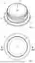
FIG. 1 shows a pouring element according to the invention in perspective view,
FIG. 2 shows the pouring element according to the invention from FIG. 1 in a plan view,
FIG. 3A shows a main body of the pouring element according to the invention in perspective view from above,
FIG. 3B shows the main body from FIG. 3A in a vertical section along the line IIIB-IIIB in FIG. 3A, partially enlarged,
FIG. 3C shows the main body from FIG. 3A in a vertical section along the line IIIC-IIIC in FIG. 3A,
FIG. 4 shows the screw cap of the pouring element according to the invention in a vertical section,
FIG. 5A shows a cutting element of the pouring element according to the invention in perspective view,
FIG. 5B shows the cutting element from FIG. 5A in a vertical section along the line VB-VB,
FIG. 6A shows the main body from FIG. 3 with the cutting element partially inserted in a vertical section before the start of assembly of the cutting element,
FIG. 6B shows the pouring element according to the invention, still without a screw cap, during the assembly of the cutting element in the main body, also in a vertical section,
FIG. 7A shows the pouring element according to the invention in a vertical section before assembling the screw cap and
FIG. 7B shows the finished pouring element in a vertical section along the line VIIB-VIIB from FIG. 2 after assembly.
DESCRIPTION OF THE INVENTION
A preferred exemplary embodiment of a pouring element 1 according to the invention is shown in the drawing. FIG. 1 shows a pouring element 1 in a fully assembled and closed condition with a vertical axis VA without a composite package. A reclosable screw cap 2, which is used for the first opening and for reclosing of the composite package, is located on a main body 3, of which only a circumferential flange 4 is visible in FIG. 1, which is used for connection with and integration into the composite package (not shown). In the plan view in FIG. 2, a VIIB-VIIB section line is also shown, which is discussed in more detail below.
In the exemplary embodiment shown and preferred in this respect, the screw cap 2 has, in addition to the actual cover element 12, an underlying anchor ring 13 and in turn a ring 14 arranged underneath. In the exemplary embodiment represented and preferred in this respect, the cover element 12 is connected to the anchor ring 13 via a one-piece Tether T, i. e. a “retaining strap”. For this purpose, the screw cap 2 is provided with at least one slot S by means of a circumferential slit blade. In the exemplary embodiment shown and preferred in this respect, two slots S are present, as is visible from FIG. 1. To produce them, two cuts are made in parallel planes. As a result, the screw cap 2 is connected via a tether T, wherein both tether arms are connected to the anchor ring 13 in one piece. In FIG. 1, however, only the front “end” of the Tether T is visible. However, it is also possible to provide only a single slot if only one attachment to the anchor ring is desired via a single end of the tether strap. In this case, the slot runs over the circumference at least partially in a helix shape such that the two ends of this slot are at different heights relative to the vertical axis VA. In addition, a design without a tether is also possible, only with a cover element 12 and with a ring 14.
The main body 3 of the pouring element 1 according to the invention, which is partially concealed in FIGS. 1 and 2 by the screw cap 2, is shown individually in FIG. 3A in a perspective view from above. It comprises a horizontal flange 4, the outer edge of which is to be sealed with the package edge of a punched opening in a composite package (not shown), as described in more detail below. It also comprises a hollow cylindrical spout 5, which has an external thread 6 and an internal thread 7. The internal thread 7 has a lower thread section 7A and an upper thread section 7B, wherein the lower thread section 7A is a fully formed thread with a full thread height and which spans a half turn of helix rotation of the internal thread 7, wherein the upper thread section 7B is flattened towards the pouring opening of the spout 5. Moreover, in the illustrated embodiment, the internal thread 7 is made from four single parallel threads.
The spout 5 has a plurality of vertical guide ribs 9 arranged on its outer circumference distributed over the circumference below the outer thread 6. The depth of the vertical guide ribs 9 corresponds approximately to the height of the external thread 6. The upper edges of all lateral guide surfaces of the vertical guide ribs 9 lie in a plane and ensure during the assembly process that the screw cap 2 is evenly widened and centred during the assembly process after having passed the external thread 6 of the spout 5. In addition to the vertical guide ribs 9, a circumferential web 10A can be found in the region of these guide ribs 9, which is not designed to be rotationally symmetrical, but instead has recesses in some regions. Parallel to this circumferential web 10A and below this, web sections 10B can also be seen which have the same outer contour as the circumferential web 10A. In addition to the aforementioned features, the guide ribs 9 or the circumferential webs 10A and web sections 10B also ensure a stiffening of the spout 5 on the side of the closure part 19. This stiffening results in a more stable guidance of the cutting element 8 during the opening process. Moreover, a plurality of vertical webs 11 can be seen below the vertical guide ribs 9 and in extension thereto as well as below the webs 10B. These vertical webs 11 serve as both locking elements on the outside and reinforcing elements for the internal thread 7.
FIG. 3B shows the main body 3 shown in FIG. 3A in a vertical section along the line IIIB-IIIB from FIG. 3A with a partial enlargement of the section of the left cylinder wall of the spout 5. Due to the different heights of threads 7A and 7B, shown as thread heights THA and THB, the respective inner diameter DA of the lower thread section 7A is smaller than the inner diameter DB of the upper thread section 7B with the flattened top, as can be more clearly seen from the enlarged portion.
At its bottom, the main body 3 has a closure part 19 with a central region 20 and comprises an annular weakening zone 21 which connects to the spout 5 and a conical annular intermediate region 22 which extends between the weakening zone 21 and the central region 20 of the base of the main body 3 and which jointly seal the pouring opening. The chamfering of the intermediate region 22 compensates for the thickness difference between the central region 20 and the weakening zone 21.
The internal thread 7 serves to accommodate a cutting element 8, which, however, is only shown starting in FIGS. 5A and 5B and is also described in more detail further below.
FIG. 3C shows a similar view as in FIG. 3B, wherein the cutting line the line IIIC-IIIC from FIG. 3A is turned clockwise about an angle of 50° compared to the line IIIB-IIIB shown in Fig. 3A. Such a design is favorable with regard to the assembly of the cutting element 8, which needs to be inserted into the cylindrical spout 5. The internal thread 7 has a reduced thread height 7B in areas where the screw thread is located in the initial position of the cutting element 8 before the composite package is initially opened (insertion zone). The transition sections from the insertion zone with a reduced thread height 7B to the adjacent sections with fully formed thread height 7A are more clearly visible in this orientation. The insertion zone is arranged in the region of the upper thread 7B, which is clearly shown with the curly bracket right of FIG. 3C. Moreover, the position of the external thread 25 of the cutting element 8 (not shown here) is indicated with a dot pattern.
This essentially serves a dual purpose. On the one hand, the application of the cutting element 8 into the cylindrical spout 5 is eased since the areas where an application would generate the highest forces have the reduced thread height 7B. On the other hand, it is advantageous that even in the initial stages there is a high enough thread overlap to guarantee a stable opening process. Later this is ensured by the lower thread section 7A. Since only the insertion zones where the screw thread 25 is initially located have a reduced height, the screw thread 25 and the internal thread 16 have a high enough thread overlap after only a short rotation of the screw cap 2 and therefore the cutting element 8. Ideally, the internal thread 16 bordering the insertion zone in the direction of opening (below and along the helix) has the same thread height as in the lower thread section 7A.
FIG. 4 shows a vertical section through the screw cap 2 of the pouring element 1 according to the invention, wherein the cover element 12, the anchor ring 13 and the ring 14 of the screw cap 2 are clearly shown. Two of a total of three force transmission elements 15, which extend downwards from the cover element 12, are also particularly clearly visible. Furthermore, an internal thread 16 can be recognised inside the cover element 12, which corresponds to the external thread 6 of the spout 5 of the main body 3. In addition, FIG. 4 shows that the anchor ring 13 has a circumferential retaining web 17 in its lower region. This is described in more detail below.
Moreover, FIG. 4 clearly shows that the ring 14 serving as a tamper-proof seal has on its inside a plurality of stop elements 18 arranged distributed over the circumference. The arrangement of the stop elements 18 is selected such that they lie in the assembled state of the pouring element 1 in the region of the vertical webs 11 as depicted in FIG. 3A. Aforementioned recesses in the circumferential webs 10A and 10B also align with these stop elements 18 to facilitate assembly. The stop elements 18 engage with the vertical webs 11 when the screw cap 2 is opened for the first time, so that a rotation of the circumferential ring 14 is reliably excluded. The vertical webs 11 are arranged in such a way that they, as can be seen clearly in FIG. 3A, are arranged below the protrusions 10A and 10B. The anchor ring 13 and ring 14 are connected to one another in a single piece via small material bridges. During the initial opening process, these material bridges break up due to the blocking catching of the circumferential ring 14 and thus signal to the consumer that the pouring element 1 has already been opened. A tamper-proof seal formed in this way is also known as a Tamper Evident element.
FIG. 5A shows a cutting element 8 individually in a perspective view. The hollow cylindrical structure of the cutting element 8 can first be seen, wherein three force accepting elements 24 evenly distributed over the circumference can be seen inside the cutting element 8, which are driven when the pouring element 1 applied to a composite package is opened initially. The drive is performed by the screw cap 2 (not shown here), which thereby causes the rotation of the cutting element 8 by means of force transmission elements 15, as described in more detail below. In addition, FIG. 5A clearly shows that the cutting element 8, which is represented and thus preferred, has a screw thread 25 on its outer side. In the preferred embodiment, the screw thread 25 comprises the same number of single parallel thread sections as the internal thread 7 of the spout 5 (without individual numerals).
The cutting element 8 from FIG. 5A is also shown in FIG. 5B in a vertical section along the line VB-VB in FIG. 5A. It is clearly discernible that between the two regions of the cutting element 8 arranged on the right and left, on which two assembly aids M1 and M2 are located at the top, a region is created which is marked with a dot pattern for better explanation, and which can serve as a flexible region F due to its significantly lower height. Outside this flexible region, the cutting element 8 is designed to be more than twice as high and also has two cutting teeth 23 in its lower region, which cannot be identified in the perspective view of FIG. 5A. The front region of the cutting element 8 from FIG. 5A also has a flexible region F: A region of significantly reduced height of the cutting element 8 between the internally arranged force accepting element 24 and the end of the reinforcement web for the cutting tooth 23 (not specified in more detail) in the bottom left in FIG. 5A.
The assembly of the main body 3 and the cutting element 8 for the pouring element 1 according to the invention is carried out by means of the following steps:
-
- Holding of the main body 3 on a base (for example with vacuum),
- Non-oriented placement of the cutting element 8 on a flat plate,
- Rotary alignment of the main body 3 and
- Relative axial movement of main body 3 and cutting element 8.
FIGS. 6A and 6B illustrate the assembly of the main body 3 and the cutting element 8 in more detail. FIG. 6A initially shows the start of assembly with the cutting element 8 just inserted partially. FIG. 6B shows the further assembly process of the cutting element 8 in the main body 3. The special embodiment of the upper edge of the cutting element 8 according to the invention can also clearly be seen in FIG. 6A. In this representation, two optional raised assembly aids M1 and M2 can be clearly seen on the right and left at the upper edge of the cutting element 8. Between these assembly aids M1 and M2, the cutting element 8 is designed flexibly and thus forms flexible regions F, of which only the rear flexible region can be seen here due to the sectional view.
The main body 3 sealed with the flange 4 at the circumferential edge of an opening in a composite package (not shown) further has a closure part 19 formed in the spout 5 in the plane of the flange 4. As already described above with regard to FIG. 3B, the closure part 19 has a central region 20 and comprises an annular weakening zone 21 which connects to the spout 5 and a conical annular intermediate region 22 which extends between the weakening zone 21 and the central region 20 of the base of the main body 3 and which jointly seal the subsequent pouring opening.
As explained further above with respect to FIGS. 5A and 5B, the cutting element 8 in the represented and in this respect preferred embodiment has two cutting teeth 23 on its underside, which are each arranged in the region below the assembly aids M1 and M2 as can be clearly seen in FIG. 6B. On its outer circumference, the hollow cylindrical cutting element 8 has a screw thread 25, which obviously hampers pressing the cutting element 8 axially into the main body 3.
As the last step of assembling the pouring element 1 according to the invention, the screw cap 2 is first aligned rotationally on the unit consisting of the main body 3 and cutting element 8 and then placed near the closure part so that the force transmission elements 15 of the cover element are arranged next to the force accepting elements 24.
In FIG. 7A, the position of the screw cap 2 is shown with reference to the main body 3 and the opening means completely inserted therein. The internal thread 16 of the cover element 12 is still arranged above the main body 3 and cutting element 8. On the left side of FIG. 7A it is visible how the retaining web 17 of the anchor ring just passes the uppermost thread of the external thread 6 of the spout 5 and how the stop element 18 of the ring 14 has already passed the external thread 6. The inner diameter of the circumferential retaining web 17 of the anchor ring 13 is slightly smaller than the outer diameter of the circumferential web 10A. However, a brief deformation of both elements is possible due to the plastic material used, wherein the circumferential retaining web 17 is widened. However, this expansion does not occur evenly over the circumference of the retaining web 17 due to the recesses present in the web 10A.
Finally, FIG. 7B shows the pouring element 1 in its fully assembled position. Between the screw cap 2 and the outer side of the spout 5 there is a first thread pair 6 and 16, which enables the screw cap 2 to be screwed on and tightened. The hollow cylindrical cutting element 8 with its cutting teeth 23 is arranged inside the main body 3, which, when the pouring element 1 and thus the composite package P is initially opened, separates the closure part 20 by destroying a partial section of the weakening zone 21. The vertical axis VA (shown only in FIG. 1) is defined by the concentrically arranged hollow cylindrical elements of the spout 5 and the cutting element 8.
The cutting element 8 rotates helically about the vertical axis VA during the opening process and moves along this axis. This helical movement is defined by a second thread pair 7 and 25, which is located between the inner side of the spout 5 and the cutting element 8 and ensures a positive guide of the cutting element 8 during its rotation. In this movement, the cutting element 8 is driven on at least one force accepting element 24 (not shown), which interacts with at least one corresponding force transmission element 15 of the screw cap 2.
Due to the special design of the internal thread 7 with an upper thread section 7B with a reduced height and a fully formed lower thread section 7A, lower forces, and therefore also less abrasion, during the assembly are achieved with the present invention. At the same time, the lower thread section 7A assures proper guidance of the cutting element 8 over the full opening process as the latter moves downwards.
List of Reference Numerals
-
- 1 Pouring element
- 2 Screw cap
- 3 Main body
- 4 Flange
- 5 Spout
- 6 External thread
- 7 Internal thread
- 7A Lower thread section
- 7B Upper thread section
- 7SE Safety element
- 8 Cutting element
- 9 Vertical guide rib
- 10A Circumferential web
- 10B Step
- 11 Vertical web
- 12 Cover element
- 13 Anchor ring
- 14 Ring (tamper-proof seal)
- 15 Force transmission element
- 16 Internal thread
- 17 Retaining web
- 18 Stop element
- 19 Closure part
- 20 Central area
- 21 Annular weakening zone
- 22 Conical annular intermediate section
- 23 Cutting tooth
- 24 Force accepting element
- 25 Screw thread
- DA Inner diameter A
- DB Inner diameter B
- F Flexible area
- M1 Assembly aid
- M2 Assembly aid
- S Slot
- T Tether
- THA Thread height of lower thread section 7A
- THB Thread height of upper thread section 7B
- VA Vertical axis
Claims
1. A pouring element for a composite package, the pouring element comprising a main body with a hollow cylindrical spout and a flange arranged at an axial end of the spout; a hollow cylindrical cutting element, guided in a movable manner in the spout, with at least one cutting tooth for opening the composite package; and a reclosable screw cap, which, when the composite package is initially opened, serves to drive the cutting element; wherein the main body, the spout, the cutting element, and the screw cap are arranged concentrically about a vertical axis and wherein the outer hollow cylinder wall of the cutting element has a screw thread, which serves as a movable guide in the spout;
wherein
the inner hollow cylinder wall of the spout has at least one internal thread having a lower thread section and an upper thread section, wherein the upper thread section of the internal thread has a radially reduced average thread height compared to the lower thread section and in that the lower thread section spans half a turn of helix rotation of the at least one internal thread on the axial end of the spout where the flange is arranged.
2. The pouring element according to claim 1,
wherein
the internal thread has a reduced thread height in an insertion zone where the screw thread is located in the initial position of the cutting element before the composite package is initially opened.
3. The pouring element according to claim 2,
wherein
the screw thread comprises at least one additional thread segment located in the region of the at least one cutting tooth.
4. The pouring element according to claim 1,
wherein
the regions of the cutting element circumferentially outside of where the at least one cutting tooth is located form flexible regions, wherein the screw thread is designed at least partially with thinner and/or less high threads.
5. The pouring element according to claim 1,
wherein
the threads of the lower thread section are fully formed with a constant thread height along their helix length.
6. The pouring element according to claim 1,
wherein
the average thread height of the upper thread section is less than 80%, preferably less than 60%, of the average thread height of the lower thread section.
7. The pouring element according to claim 2,
wherein
the thread height of the internal thread in said insertion zone is less than 70% of the average thread height of the lower thread section.
8. The pouring element according to claim 1,
wherein
both the average thread height of the lower thread section FA and the thread height of the screw thread span more than 75% of the difference between the radii of the inner hollow cylinder wall of the spout and the outer hollow cylinder wall of cutting element.
9. The pouring element according to claim 1,
wherein
the thread width of the at least one internal thread, measured along the vertical axis at the base of the at least one internal thread, is constant along the thread irrespective of any changes in thread height.
10. The pouring element according to claim 1,
wherein
the height of the upper internal threads in the outermost third of the hollow cylindrical spout, viewed along the vertical axis, decreases steadily towards the pouring opening, preferably the spout also being funnel-shaped above the at least one internal thread.
11. The pouring element according to claim 1,
wherein
the outer thread and the internal thread comprise more than one, preferably four, thread starts.
12. The pouring element according to claim 1,
wherein
the lower thread section is further stabilized by vertical webs located on the outside of the hollow cylindrical spout.
13. The pouring element according to claim 1,
wherein
the upper thread section of the spout comprises a safety element located in a region of the spout remote from the flange to mechanically hold the cutting element in place before and during assembly.
14. The pouring element according to claim 1,
wherein
the main body has a closure part with a central region and preferably comprises an annular weakening zone which connects to the spout.
15. A package, in particular cardboard/plastic composite package,
wherein
it is provided with a pouring element according to claim 1.
Images & Drawings included:


Sources:
- United States Patent and Trademark Office - verify current appl. status at the USPTO↗
Recent applications in this class:
- » 20260008586 2026-01-08
SPOUT PACKAGING STRUCTURE OF PACKAGING BOX, AND PACKAGING BOX - » 20250304316 2025-10-02
SPOUT FOR A CONTAINER AND PACKAGE-SPOUT ASSEMBLY - » 20250256885 2025-08-14
OPENING DEVICE FOR A PACKAGE AND PACKAGE THEREWITH - » 20250197056 2025-06-19
CONTAINER ELEMENT WITH INCLINED SIDE WALLS FOR DIMENSIONALLY STABLE FOODSTUFF CONTAINER - » 20240367850 2024-11-07
Tethered Cap and Spout - » 20240217698 2024-07-04
OPENING DEVICE FOR A PACKAGE AND PACKAGE - » 20240150068 2024-05-09
Pouring Element and Composite Package With Improved Opening Behaviour - » 20240140644 2024-05-02
Pouring Element and Composite Package With Improved Opening Behaviour - » 20230150719 2023-05-18
Opening device for a sealed package and a sealed package provided with an opening device - » 20230044435 2023-02-09
SPOUT FOR A CONTAINER AND PACKAGE-SPOUT ASSEMBLY