CARRIER PLATFORM FOR HOUSEHOLD DEVICES
US20260116619A1
2026-04-30
19/362,690
2025-10-20
Smart Summary: A carrier platform is designed to hold household appliances securely. It features several support structures that are arranged in parallel and spaced apart. These structures include lower plate parts that are flat and sit parallel to the ground. To add strength, there are reinforcement parts placed between the lower plates. Additionally, an intermediate support part is positioned between the lower plates and the reinforcement parts for extra stability. 🚀 TL;DR
Abstract:
A carrier platform, particularly a pallet for supporting a household appliance, has multiple parallel and spaced-apart support structures and one or more upper plate parts that extend in a depth direction and connect the support structures to each other. The support structures have a couple of spaced-apart planar lower plate parts parallel to the ground. Reinforcement support parts are disposed in a space between the lower plate parts of the support structures and separated from each other at the mutual end sides in a width direction of the carrier platform. The support structures have an intermediate support part disposed in the space between the lower plate parts and between two of the reinforcement support parts.
Inventors:
- ERHAN KAYA 11 🇹🇷 TEKIRDAG, Turkey
- Onur Hancerkiran 2 🇹🇷 Tekirdag, Turkey
- Aytek ACAR 1 🇹🇷 Tekirdag, Turkey
Applicant:
Interested in similar patents?
Get notified when new applications in this technology area are published.
Classification:
B65D19/0095 » CPC main
Pallets or like platforms, with or without side walls, for supporting loads to be lifted or lowered; Rigid pallets without side walls the load supporting surface being made of more than one element forming discontinuous or non-planar contact surfaces the base surface being made of more than one element forming discontinuous or non-planar contact surfaces and each contact surface having a stringer-like shape
B65D19/38 » CPC further
Pallets or like platforms, with or without side walls, for supporting loads to be lifted or lowered Details or accessories
B65D2519/00029 » CPC further
Pallets or like platforms, with or without side walls, for supporting loads to be lifted or lowered; Details relating to pallets; Materials for the load supporting surface Wood
B65D2519/00064 » CPC further
Pallets or like platforms, with or without side walls, for supporting loads to be lifted or lowered; Details relating to pallets; Materials for the base surface Wood
B65D2519/00089 » CPC further
Pallets or like platforms, with or without side walls, for supporting loads to be lifted or lowered; Details relating to pallets; Materials for the non-integral separating spacer Paper
B65D2519/00099 » CPC further
Pallets or like platforms, with or without side walls, for supporting loads to be lifted or lowered; Details relating to pallets; Materials for the non-integral separating spacer Wood
B65D2519/00273 » CPC further
Pallets or like platforms, with or without side walls, for supporting loads to be lifted or lowered; Details relating to pallets; Overall construction of the pallet made of more than one piece
B65D2519/00293 » CPC further
Pallets or like platforms, with or without side walls, for supporting loads to be lifted or lowered; Details relating to pallets; Overall construction of the load supporting surface made of more than one piece
B65D2519/00323 » CPC further
Pallets or like platforms, with or without side walls, for supporting loads to be lifted or lowered; Details relating to pallets; Overall construction of the base surface made of more than one piece
B65D2519/00333 » CPC further
Pallets or like platforms, with or without side walls, for supporting loads to be lifted or lowered; Details relating to pallets; Overall construction of the base surface shape of the contact surface of the base contact surface having a stringer-like shape
B65D2519/00378 » CPC further
Pallets or like platforms, with or without side walls, for supporting loads to be lifted or lowered; Details relating to pallets; Overall construction of the non-integral separating spacer whereby at least one spacer is made of two or more pieces
B65D2519/00417 » CPC further
Pallets or like platforms, with or without side walls, for supporting loads to be lifted or lowered; Details relating to pallets; Overall construction reinforcements; Integral, e.g. ribs on the non-integral separating spacer
B65D2519/00562 » CPC further
Pallets or like platforms, with or without side walls, for supporting loads to be lifted or lowered; Details relating to pallets; Connections; Structures connecting the constitutive elements of the pallet to each other, i.e. load supporting surface, base surface and/or separate spacer without separate auxiliary elements chemical connection, e.g. glued, welded, sealed
B65D19/00 IPC
Pallets or like platforms, with or without side walls, for supporting loads to be lifted or lowered
Description
CROSS-REFERENCE TO RELATED APPLICATION
This application claims the priority, under 35 U.S.C. § 119, of Turkish Patent Application TR 2024/014521, filed Oct. 24, 2024; the prior application is herewith incorporated by reference in its entirety.
FIELD AND BACKGROUND OF THE INVENTION
The present invention relates to a carrier platform embodiment or, simply, a carrier platform.
Household devices, for instance cooling devices such as refrigerators, are placed on carrier platforms, particularly on pallets while they are being carried from one place to another place. A carrier platform which belongs to the prior art is shown in FIG. 18. It comprises at least one support structure. Each support structure has a first lower plate part, a second lower plate part and a filling element which longitudinally fills the space between the lower plate parts. Expanded polystyrene (EPS) is used as the filling element. Expanded polystyrene (EPS), however, is not a sustainable and environment-friendly material.
U.S. Pat. No. 5,492,267 discloses a package produced in big amounts and which is for protecting degradable food products transferred on the pallet, and panels made of comb material coated with aluminum foil panels for providing a stronger and better insulated package.
There is room for further improvement, for additions to and alternatives for the prior art.
SUMMARY OF THE INVENTION
It is accordingly an object of the invention to provide a carrier platform which overcomes a variety of disadvantages of the heretofore-known devices and methods of this general type and which provides for an alternative carrier platform embodiment which has a good damping feature for household devices during transportation and which is more environment-friendly.
With the above and other objects in view there is provided, in accordance with the invention, a carrier platform, in particular a carrier platform embodiment upon which a household device can be seated. The carrier comprises:
-
- a plurality of support structures disposed parallel to one another at a side of the carrier platform embodiment that is close to a ground on which said support structures are seated;
- at least one upper plate part extending in a depth direction and connecting said support structures to one another at a side of the carrier platform embodiment distal from the ground;
- each of said support structures being formed with at least two planar lower plate parts disposed at a spacing distance from one another and substantially parallel to the ground;
- each of said support structures including reinforcement support parts filling a space between said lower plate parts and separated from each other at mutual end sides in a width direction of the carrier platform embodiment; and
- each of said support structures including at least one intermediate support part filling the space between said lower plate parts of said support structures and being disposed next to one of said reinforcement support parts.
In other words, the above and other objects are achieved, in accordance with the invention, by a carrier platform, particularly a carrier platform embodiment where a household device can be seated, comprising more than one support structure provided to be essentially in parallel direction to each other at a side of the carrier platform embodiment which is close to a ground where the support structure is seated, and at least one upper plate part which extends in a depth direction in a manner connecting the support structures to each other at a side of the carrier platform embodiment which is further to the ground, and wherein each of the support structures comprises a couple of planar lower plate parts provided in a distanced manner to each other and positioned in essentially parallel planes to the ground, wherein each of the support structures comprises reinforcement support parts provided in a manner filling a space between the related lower plate parts of the support structures and provided in a separate manner from each other at the mutual end sides in a width direction of the carrier platform embodiment and each of the support structures (comprises at least one intermediate support part provided in a manner filling the space between the related lower plate parts of the support structures and wherein the at least one intermediate support part is positioned next to one of the reinforcement support parts. By means of this, carrier platform embodiment is provided which is more environment-friendly and which has the desired damping feature even in case the carrier platform embodiment falls to the ground from a specific height at a condition where a household device is placed on the carrier platform embodiment. By means of the intermediate support parts, the carrier platform embodiment is arranged in a manner carrying a part of the household device weight in order to prevent overturning of the household device towards the side and corner regions. Here, the reinforcement support parts provide a damping function against load.
With the above and other objects in view there is also provided, in accordance with the invention, a carrier platform, which is particularly suited for supporting a household appliance, and which comprises:
-
- at least one support structure formed with two planar lower plate parts disposed at a distance from one another in a height direction and substantially parallel to the ground;
- said at least one support structure including two reinforcement support parts disposed in a space between said lower plate parts of said at least one support structure and disposed separately from one another at mutual end sides in a width direction of the carrier platform;
- said at least one support structure including at least one intermediate support part disposed in the space between said lower plate parts of said at least one support structure; and
- wherein said at least one intermediate support part is positioned inwards with respect to said reinforcement support parts in the width direction, and wherein said at least one intermediate support part has a Young's modulus that is greater than Young's modulus of said reinforcement support parts.
Here, the term “household device” or “household appliance” describes any domestic cooling device, for instance, a refrigerator, a freezer, or any cooling device which includes cooling and freezing functions. Further, the “household device” or “appliance” may be a household oven, a household washing machine, a dryer, or a domestic dishwasher.
Here, term “carrier platform embodiment” or “carrier platform” describes any platform embodiment that is configured to carry a household device, for instance, a pallet embodiment.
Here, the term “upper plate part” describes a part which is essentially provided in a plate form, for example a timber part or a timber plate.
Here, the term “lower plate parts” describes parts which are essentially provided in a plate form, for example timber parts or timber plates. Each support structure comprises a couple or pair (i.e., two) of the lower plate parts. Both lower plate parts can have the same dimension and shape. They may be positioned at different height levels. In a projection plane perpendicular to the height direction both lower plate parts may fully overlap.
Here, the term “reinforcement support part” describes any reinforcement support part which fills the space between the lower plate parts only at mutual end sides and which provides damping against load. Here, the expression “filling the space between the lower plate parts” means that the object extends in height direction between both lower plate parts from one lower plate part to the other lower plate part. In particular, the object may be positioned adjacent both lower plate parts in height direction.
Here, the at least one “intermediate support parts” describes parts, for instance timber parts, particularly wooden wedge parts provided next to the reinforcement support parts. The intermediate support part may be positioned adjacent a reinforcement support part, i.e. contacting that reinforcement support part. Alternatively, there may be a free space between the two, i.e., a spacing distance between them.
In a possible embodiment Young's modulus of the intermediate support part is higher than Young's modulus of the reinforcement support part. This may in particular apply in height direction.
In a possible embodiment of the invention, each of the reinforcement support parts is reinforcement support parts made from a cellulose-based material, for example from a cardboard material. By means of this, a carrier platform embodiment is provided, which is more environment-friendly and which comprises a recyclable reinforcement support part. Thus, carrier platform embodiment comprising sustainable reinforcement support part is provided.
Here, the term “cellulose-based material” describes for instance a paper-based material, particularly a cardboard material or a paperboard material or craft paper. The cellulose-based material can include different proportions of substances like cellulose, lignin, hemi-cellulose, xylan, wax and resin. For instance, the cellulose-based material can include approximately 40% cellulose, approximately 25-30% lignin, approximately 25-30% hemi-cellulose, approximately 2% xylan, and approximately 3-5% wax and resin.
In a possible embodiment of the invention, each of the reinforcement support parts has a support embodiment embodied by bringing together mutual outer layer parts provided essentially in a planar manner, and multiple support units provided between the outer layer parts. By means of this, the reinforcement support parts are easily held between the lower plate parts. By means of the outer layer parts essentially provided in a planar manner, the holding surface is increased. By means of multiple support units, the reinforcement support part exhibits a damping feature against load.
Here, the term “multiple support units” describes support units which have a specific shape and dimension and are arranged side by side in a sequenced manner.
Here, the term “support embodiment” describes a support structure provided by multiple support units formed by support units by coming together.
In a possible embodiment of the invention, the multiple support units are provided in hollow form in a manner extending essentially in a height direction between the outer layer parts, and each multiple support unit has a support wall embodied essentially in hexagonal form. By means of this, the multiple support units show a better damping feature against load. Here, by bringing together the support walls embodied essentially in hexagonal form, a structure which is similar to a honeycomb structure is obtained.
In a possible embodiment of the invention, an adhesive element is provided between the related lower plate part and a related adhesion face of the outer layer parts which faces the related lower plate part. By means of this, separation of the reinforcement support part from the lower plate parts is prevented.
Here, said “adhesive element” can be a liquid-based adhesive or a strip-based adhesive. The liquid-based adhesive can be for instance a silicon-based adhesive, a glue, a bead glue, etc. The strip-based adhesive can be a strip band, particularly a double-sided band, etc.
In a possible embodiment of the invention, the intermediate support parts are intermediate support parts made from a wooden material, particularly made from a pine tree timber. By means of this, the intermediate support parts have long lifetime and resistance. Particularly by usage of pine tree timber, besides obtaining high shock resistance and strength, resistance against water is also increased.
In a possible embodiment of the invention, the support structures are the first support structure provided at a front side, a third support structure provided at a rear side which is at the opposite side of the front side, and a second support structure positioned at a region between the first support structure and the third support structure, such that the second support structure is provided in a closer manner to the first support structure or such that there is equal distance between the second support structure and the first support structure and the third support structure. There is a wider door at the front side of wider household devices. This leads a heavier weight at the front side of the household device. Therefore, by providing the second support structure to be closer to the first support structure, load can be carried in a safer manner particularly for wider household devices. For narrower household devices, positioning of the second support structure such that there is equal distance between the second support structure and the first support structure and the third support structure is sufficient for carrying the load in a safe manner.
In case there are two intermediate support parts and each intermediate support part is positioned next to a reinforcement support part, there may in a possible embodiment of the invention at least one additional intermediate support part positioned in the space which exists between the intermediate support parts. There is a wider door at the front side of wider household devices. This leads to a bigger weight at the front side of the household device. Since the width of the household device is big, a depression in the middle region of the second lower plate part due to the big weight and due to the increase in the distance between mutual end regions of the support structures is prevented.
Here, the term “additional intermediate support part” describes for instance timber parts, particularly wooden wedge parts. The additional intermediate support parts can be identical with the intermediate support parts. The additional intermediate support parts can be made from the same material or a different material from intermediate support parts. The additional intermediate support parts can be made in the same or different dimensions from the intermediate support parts. In a preferred embodiment, the additional intermediate support parts and the intermediate support parts are made of the same material, and they have the same dimensions.
In a possible embodiment of the invention, the support structures are provided as shaped and dimensioned in identical structures with each other. By means of this, identical support structures are provided which show the same damping effect in every region of the carrier platform embodiment.
In a possible embodiment of the invention, a reinforcement width of the reinforcement support part is the same as or bigger than an upper plate width of the upper plate part. By means of this, the reinforcement support part shows the expected damping feature against load.
In a possible embodiment of the invention, there are at least three upper plate parts positioned in a distanced manner in the width direction with respect to each other. By means of this, the load, formed by the weight of the household device, is distributed in the width and depth direction.
In a possible embodiment of the invention, the intermediate support parts and the additional intermediate support parts are provided in a manner connected to the lower plate parts by means of at least one connection element. By means of this, during transportation of the household device, probable separation of the intermediate support part and the additional intermediate support part from the carrier platform embodiment is prevented.
Here, the term “connection element” describes any connection element which can connect two parts, preferably two wooden parts to each other in a removable manner. For instance, the connection element may be a removable connection element such as a screw or a nail.
In a possible embodiment of the invention, at least two connection elements are provided for connecting the intermediate support parts and the additional intermediate support parts to the related first lower plate part, and at least two connection elements are provided for connecting the intermediate support parts and the additional intermediate support parts to the related second lower plate part. By means of this, the connection of the intermediate support parts and the additional intermediate support parts to the lower plate parts is further reinforced.
In a possible embodiment of the invention, the connection elements are configured to pass in crosswise direction through the related lower plate part and to hold to the related intermediate support part. By means of this, the path followed by the connection element in the intermediate support parts and in the additional intermediate support parts is extended, thus, connection of the intermediate support parts and the additional intermediate support parts is further reinforced. Moreover, separation of the related intermediate support parts from the lower plate parts as a result of the external forces, exerted in different directions to the related intermediate support parts in cases where the carrier platform embodiment falls to the ground from a specific height, is prevented.
In a possible embodiment of the invention, the lower plate parts and the upper plate parts are made from a wood material, particularly from a beech tree timber. By means of this, usage of a material, which has a denser texture and which is hard and strong, for distributing and carrying of the load which occurs due to the weight of the household device, increases resistance against bending, decaying and cracking. Particularly usage of beech tree timber also increases the resistance of the carrier platform embodiment against water.
It will be understood that each of the possible embodiments described herein can be combined with the other possible embodiments disclosed herein, assuming there is no technical constraint against the combination.
Other features which are considered as characteristic for the invention are set forth in the appended claims.
Although the invention is illustrated and described herein as embodied in a carrier platform embodiment for household devices, it is nevertheless not intended to be limited to the illustrated details, since various modifications and structural changes may be made therein without departing from the spirit of the invention and within the scope and range of equivalents of the claims.
The construction and method of operation of the invention, however, together with additional objects and advantages thereof will be best understood from the following description of specific embodiments when read in connection with the accompanying drawing.
BRIEF DESCRIPTION OF THE FIGURES
The figures, whose brief explanations are herewith provided, are solely intended for providing a better understanding of the present invention and are as such not intended to define the scope of protection or the context in which said scope is to be interpreted in the absence of the description.
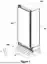
FIG. 1 is a representative isometric view of the condition where a household device is placed onto the first embodiment of the subject matter carrier platform embodiment.
FIG. 2 is an enlarged side view of the condition where the household device is placed onto the first embodiment of the subject matter carrier platform embodiment.
FIG. 3 is an isometric view of the first embodiment of the subject matter carrier platform embodiment.
FIG. 4 is a frontal view of the first embodiment of the subject matter carrier platform embodiment.
FIG. 5 is another frontal view of the first embodiment of the subject matter carrier platform embodiment.
FIG. 6 is a side view of the first embodiment of the subject matter carrier platform embodiment.
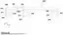
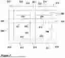
FIG. 7 is a bottom view of the first embodiment of the subject matter carrier platform embodiment.
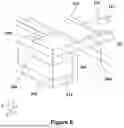
FIG. 8 is a zoomed isometric view of the first embodiment of the subject matter carrier platform embodiment.
FIG. 9 is an isometric view of the second embodiment of the subject matter carrier platform embodiment.
FIG. 10 is a frontal view of the second embodiment of the subject matter carrier platform embodiment.
FIG. 11 is another frontal view of the second embodiment of the subject matter carrier platform embodiment.
FIG. 12 is a side view of the second embodiment of the subject matter carrier platform embodiment.
FIG. 13 is a bottom view of the second embodiment of the subject matter carrier platform embodiment.
FIG. 14 is an isometric view of the reinforcement support part provided in the subject matter carrier platform embodiment.
FIG. 15 is an isometric view in a manner showing the support embodiment of the reinforcement support part provided in the subject matter carrier platform embodiment.
FIG. 16 is a top view showing the support embodiment of the reinforcement support part provided in the subject matter carrier platform embodiment.
FIG. 17 is a frontal view of the reinforcement support part provided in the subject matter carrier platform embodiment.
FIG. 18 is an isometric view of a carrier platform embodiment that belongs to the prior art.
DETAILED DESCRIPTION OF THE INVENTION
The “width direction (x)” describes a width direction of the household device (100), of the body (101), of the carrier platform embodiment (200), of the related support structures (201, 202, 203), of the related intermediate support parts (211), of the related additional intermediate support parts (221) or of the related reinforcement support part (212).
The “height direction (y)” describes a height direction of the household device (100), of the body (101), of the carrier platform embodiment (200), of the related support structures (201, 202, 203), of the related intermediate support parts (211), of the related additional intermediate support parts (221) or of the related reinforcement support part (212).
The “depth direction (z)” describes a depth direction of the household device (100), of the body (101), of the carrier platform embodiment (200), of the related support structures (201, 202, 203), of the related intermediate support parts (211), of the related additional intermediate support parts (221) or of the related reinforcement support part (212).
The x-y-z directions of the Cartesian coordinate system are with respect to a carrier platform embodiment placed on the ground and a household device placed on the carrier platform embodiment in an upright manner. With reference to a horizontal ground, the coordinates x (width) and z (depth) are horizontal and the coordinate y (height) is vertical.
Referring now to the figures of the drawing in detail and first, in particular, to FIG. 1 thereof, there is shown a representative isometric view of a condition where a household device (100), for instance a cooling device is seated onto the subject matter carrier platform embodiment (200), namely on the pallet embodiment. The household device (100) comprises a body (101) which has a lower wall, an upper wall, a rear wall and a first side wall and a second side wall provided mutually to each other. The body (101) is provided in a manner encircling at least one compartment wherein the objects can be placed. Since the household device given in FIG. 1 is a cooling device, said compartment is at least one storage compartment (not illustrated in the figures). There is a front opening (not illustrated in the figures) at a device front side of the household device (100) in a manner providing access to the storage compartment from outside. The household device (100) also comprises at least one door (102) connected to the body (101) in a rotatable manner by means of hinge assemblies. In a closed position of the door (102) as in FIG. 1, the front opening is completely covered, and in this case, access to the storage compartment from outside is prevented. In other words, in the closed position of the door (102), the storage compartment (3) is completely isolated from the outer medium. In an open position where the door (102) is at least partially open, access from outside can be provided into the storage compartment through the front opening. The door (102) is configured to move between an open position and a closed position. The subject matter carrier platform embodiment (200) is provided in a manner seating onto a ground (G). In FIG. 1, the household device (100) is placed on a first embodiment of the carrier platform embodiment (200). In other words, the carrier platform embodiment (200) is positioned between the ground (G) and the household device (100).
As shown in FIG. 2, the household device (100) has at least one wheel (104) and at least one carrier foot (103). Preferably, at the opposite sides of the household device (100), there are multiple wheels (104) and multiple feet (103). The carrier feet (103) can have a structure which can be adjusted in the upward-downward direction. The wheels (104) have a structure which is rotatable in an axis. When the household device (100) is positioned on the carrier platform embodiment (200), the wheels (104) provided at the front side are rested to a side face (222) of the carrier platform embodiment (200) which exists at the related stop plate part (210). In this case, the carrier feet (103), which exist at the front side, are rested to a second upper face (215) of the stop plate part (210) which faces the household device (100). As shall be seen in FIG. 3, there is one each stop plate parts (210) provided essentially in plate form at the opposite sides of the household device (100) in width direction (x). Said stop plate parts (210) can be made from a wood material, for instance, from beech tree timber.
With reference to FIG. 3, there is more than one support structure (201, 202, 203) provided in an essentially parallel manner to each other at a side of the first embodiment of the carrier platform embodiment (200) which is close to the ground (G) where said carrier platform embodiment (200) is seated. The support structures (201, 202, 203) are essentially provided in a manner extending in the width direction (x). The width of the support structures (201, 202, 203) also define the width of the carrier platform embodiment (200). The width of the support structures (201, 202, 203) can be determined in accordance with the width of the household device (100). There are preferably three support structures in the first embodiment of the carrier platform embodiment (200): a first support structure (201), a second support structure (202) and a third support structure (203). The support structures (201, 202, 203) are provided in a distanced manner to each other in a depth direction (z). The first support structure (201) is provided at a front side of the carrier platform embodiment (200). There is the third support structure (203) provided at a rear side which is at the opposite side of the front side. The second support structure (202) is positioned in a region between the first support structure (201) and the third support structure (203). In the first embodiment of the carrier platform embodiment (200), as shall be seen in FIG. 6, the second support structure (202) is positioned in a manner closer to the first support structure (201). Each of the support structures (201, 202, 203) comprises two reinforcement support parts (212) provided in a distanced manner from each other at the mutual end sides (K) in the width direction (x) of the carrier platform embodiment (200). In FIG. 8, the zoomed view of the reinforcement support part (212), provided between the lower plate parts (204, 205) at one side of the first support structure (201), is given. The support structures (201, 202, 203) moreover comprise the related intermediate support parts (211) provided so as to be next to and in particular in this case adjacent to the related reinforcement support parts (212). Here, the intermediate support parts (211) are intermediate support parts made from a wood material, particularly from a pine tree timber. Each of the support structures (201, 202, 203) essentially comprises a couple of planar lower plate parts (204, 205) provided in a distanced manner to each other and to be in an essentially parallel plane to the ground (G). In the support structures (201, 202, 203), a reinforcement support part (212) is provided in a manner filling a space between the related lower plate parts (204, 205). That is, the reinforcement support parts (212) extend in height direction between the related lower plate parts (204, 205) of a support structures (201, 202, 203) being in contact with both lower plate parts (204, 205). Each of said reinforcement support parts (212) is a reinforcement support part made from a cellulose-based material, particularly from a cardboard material. The support structures (201, 202, 203) are provided in a manner shaped and dimensioned in identical structure with each other. With reference to FIGS. 14-17, each of the reinforcement support parts (212) has mutual outer layer parts (216, 217) provided in an essentially planar manner, namely, a first outer layer part (216) and a second outer layer part (217). The reinforcement support parts (212) also have a support structure (218) embodied by bringing together multiple support units (223) provided between the outer layer parts (216, 217). The multiple support units (223) are provided in hollow form in a manner extending essentially in a height direction (y) between the outer layer parts (216, 217). Each multiple support unit (223) has a support wall (224) embodied essentially in hexagonal form. As shall be seen in FIG. 15, the edge parts of the multiple support unit (223) can be provided in semi-hexagonal form whose one side is cut. By bringing together the support walls (224) embodied essentially in hexagonal form, a structure which is similar to a honeycomb is obtained. Each of the outer layer parts (216, 217) has a related adhesion face (225, 226) which faces the related lower plate part (204, 205). An adhesive element (219) is provided between the related adhesion face (225) and the related lower plate part (204, 205). In more details, as shall also be seen in FIG. 4, there is an adhesive element (219), for instance a liquid-based adhesive element between the first lower plate part (204) and the lower adhesion face (226), and between the second lower plate part (205) and the upper adhesion face (225). By means of this, the reinforcement support parts (212) are fixed to the related lower plate parts (204, 205). There are lower plate parts (204, 205) in a carrier platform (300) which belongs to the known state of the art and given in FIG. 18. However, in FIG. 18, in the space between the lower plate parts (204, 205), there is a filling element (301), for instance an expanded polystyrene (EPS) which extends longitudinally in the width direction (x).
With reference to FIG. 3, there is a related at least one upper plate part (206, 207, 208) which extends in a depth direction (z) in a manner connecting the support structures (201, 202, 203) to each other at a side of the carrier platform embodiment (200) which is further to the ground (G). The upper plate parts (206, 207, 208) are provided in a distanced manner to each other in the width direction (x) of the carrier platform embodiment (200). Preferably there are at least three upper plate parts (206, 207, 208) positioned in a distanced manner in the width direction (x) with respect to each other. The upper plate parts are a first upper plate part (206) provided in the region which is close to a left side of the carrier platform embodiment (200), a third upper plate part (208) provided in the region which is close to a right side of the carrier platform embodiment (200), and a second upper plate part (207) positioned in a region between the first upper plate part (206) and the third upper plate part (208). The lower plate parts (204, 205) and the upper plate parts (206, 207, 208) are made from a wood material, particularly from a beech tree timber. In the first embodiment of the carrier platform embodiment (200), there is at least one additional intermediate support part (221) positioned in the space between the intermediate support parts (211). Preferably, there is only one additional intermediate support part (221) in each support structure (201, 202, 203). The additional intermediate support parts (221) and the intermediate support parts (211) can be identical parts. As shall be seen in FIG. 7, preferably in each support structure (201, 202, 203), there are two reinforcement support parts (212), two intermediate support parts (211) and an additional intermediate support part (221). In this case, in the first embodiment of the carrier platform embodiment (200), there are totally six reinforcement support parts (212), six intermediate support parts (211) and three additional support parts (221). There is a planar support plate part (209) at an upper side of the upper plate parts (206, 207, 208) which is further from the ground (G). Said support plate part (209) extends essentially in a parallel direction to the support structures (201, 202, 203), namely, extends essentially in the width direction (x). The support plate part (209) is positioned in a manner close to the front side of the carrier platform embodiment (200). The support plate part (209) has a first upper face (214) where an outer package of the household device (100) is rested on. On the other hand, there is at least one stop plate part (210) provided in a further manner to the front side of the carrier platform embodiment (200) with respect to the support plate part (209). At the opposite sides of the carrier platform embodiment (200), there is a couple of stop plate parts (210) provided mutually to each other. One of the stop plate parts (210) is provided on the first upper plate part (206), the other one of the stop plate parts (210) is provided on the third upper plate part (208). As also described before and as shall be seen in FIG. 2, when the household device (100) is positioned on the carrier platform embodiment (200), the wheels (104) provided at the front side are rested to the side face (222) that exists at the related stop plate part (210) of the carrier platform embodiment (200). In this case, the carrier feet (103) which exist at the front side are rested to the second upper face (215) of the stop plate part (210) which faces the household device (100).
With reference to FIG. 4, the intermediate support parts (211) and the additional intermediate support parts (221) are provided in a manner connected to the lower plate parts (204, 205) for instance by means of a nail or screw. There are at least two connection elements for the connection of the intermediate support parts (211) and the additional intermediate support parts (221) to the first lower plate part (204), and there are at least two connection elements for the connection of the intermediate support parts (211) and the additional intermediate support parts (221) to the second lower plate part (205). Preferably, there are three connection elements for the connection of the intermediate support parts (211) and the additional intermediate support parts (221) to the first lower plate part (204) and there are three connection elements for the connection of the intermediate support parts (211) and the additional intermediate support parts (221) to the second lower plate part (205). The connection elements (220) are configured to pass in a crosswise direction through the related lower plate part (204, 205) and to hold to the related intermediate support part (211, 221).
With reference to FIG. 5, a reinforcement width (w2) of the reinforcement support part (212) is embodied to be the same as or bigger than an upper plate width (w3) of the upper plate part (206, 207, 208). Preferably, the reinforcement width (w2) is embodied to be bigger than the upper plate width (w3). On the other hand, the reinforcement width (w2) is provided to be equal to a space width (w1) of at least the intermediate space (213). A support part width (w4) of the intermediate support parts (211) is a parameter which is changeable with respect to the reinforcement width (w2). As shown in FIG. 5 the intermediate support parts (211) are positioned inwards with respect to the reinforcement support parts (212) in width direction (x). Furthermore, the Young's modulus of the intermediate support part (211) is higher than the Young's modulus of the reinforcement support parts (212).
FIGS. 9-13 are the views of a second embodiment of the carrier platform embodiment (200). All of the descriptions given above for the first embodiment of the platform embodiment (200) are also valid in the same manner for the second embodiment of the carrier platform embodiment (200). The second embodiment of carrier platform embodiment (200) has a smaller width when compared with the first embodiment. Therefore, the second embodiment is suitable for usage for narrower household devices, for instance, for single-door cooling devices. In the second embodiment of the carrier platform embodiment (200) which is different from the first embodiment, as shall be seen in FIG. 12, the second support structure (202) is provided such that there is equal distance to the first support structure (201) and to the third support structure (203). In other words, the distance of the second support structure (202) to the first support structure (201) and to the third support structure (203) in the depth direction (z) is provided to be equal. Moreover, in the support structures (201, 202, 203) that exist in the second embodiment of the carrier platform embodiment (200), there are no additional intermediate support parts (221). In other words, as shall be seen in FIG. 13, in each support structure (201, 202, 203), there are two reinforcement support parts (212) and two intermediate support parts (211). In this case, in the second embodiment of the carrier platform embodiment (200), there are totally six reinforcement support parts (212) and six intermediate support parts (211). The descriptions of the first embodiment of the carrier platform embodiment (200) by referring to FIG. 4 and FIG. 5 above, are also valid in the same manner for the similar views existing in FIG. 10 and FIG. 11 showing the second embodiment of the carrier platform embodiment (200). As shown in FIG. 10 the intermediate support parts (211) are positioned inwards with respect to the reinforcement support parts (212) in width direction (x).
The following is a summary list of reference numerals and the corresponding structure used in the above description of the invention:
-
- 100 Household device
- 101 Body
- 102 Door
- 103 Carrier foot
- 104 Wheel
- 200 Carrier platform embodiment
- 201 First support structure
- 202 Second support structure
- 203 Third support structure
- 204 First lower plate part
- 205 Second lower plate part
- 206 First upper plate part
- 207 Second upper plate part
- 208 Third upper plate part
- 209 Support plate part
- 210 Stop plate part
- 211 Intermediate support part
- 212 Reinforcement support part
- 213 Intermediate space
- 214 First upper face
- 215 Second upper face
- 216 First outer layer part
- 217 Second outer layer part
- 218 Support structures
- 219 Adhesive element
- 220 Connection element
- 221 Additional intermediate support part
- 222 Side face
- 223 Support unit
- 224 Support wall
- 225 Upper adhesion face
- 226 Lower adhesion face
- 300 Carrier platform
- 301 Filling element
- w1 Space width
- w2 Reinforcement width
- w3 Upper plate width
- w4 Support part width
- x Width direction
- y Height direction
- Z Depth direction
- G Ground
- K End side
Claims
1. A carrier platform, comprising:
a plurality of support structures disposed parallel to one another at a side of the carrier platform embodiment that is close to a ground on which said support structures are seated;
at least one upper plate part extending in a depth direction and connecting said support structures to one another at a side of the carrier platform embodiment distal from the ground;
each of said support structures being formed with at least two planar lower plate parts disposed at a spacing distance from one another and substantially parallel to the ground;
each of said support structures including reinforcement support parts filling a space between said lower plate parts and separated from each other at mutual end sides in a width direction of the carrier platform embodiment; and
each of said support structures including at least one intermediate support part filling the space between said lower plate parts of said support structures and being disposed next to one of said reinforcement support parts.
2. The carrier platform according to claim 1, wherein each of said reinforcement support parts is a reinforcement support part made from a cellulose-based material.
3. The carrier platform according to claim 2, wherein said cellulose-based material is cardboard material.
4. The carrier platform according to claim 2, wherein each of said reinforcement support parts includes substantially planar support structures disposed between outer layer parts and a plurality of support units provided between said outer layer parts.
5. The carrier platform according to claim 4, wherein said support units are hollow structures extending substantially in a height direction between said outer layer parts, and each of said support units has a support wall in hexagonal form.
6. The carrier platform according to claim 4, further comprising an adhesive element disposed between said lower plate part and a related adhesion face of said outer layer parts which faces said lower plate part.
7. The carrier platform according to claim 1, wherein said intermediate support parts are intermediate support parts made from a wood material.
8. The carrier platform according to claim 7, wherein said intermediate support parts are made from pine tree timber.
9. The carrier platform according to claim 1, wherein:
said support structures include a first support structure disposed at a front side, a third support structure disposed at a rear side opposite the front side, and a second support structure disposed in a region between said first and third support structures; and
said second support structure is disposed closer to said first support structure than to said third support structure, or said second support structure is equidistant from said first and third support structures.
10. The carrier platform according to claim 1, further comprising at least one additional intermediate support part positioned in a space between said intermediate support parts.
11. The carrier platform according to claim 1, wherein said support structures are identically shaped and dimensioned.
12. The carrier platform according to claim 1, wherein a reinforcement width of said reinforcement support part is equal to, or greater than, an upper plate width of said upper plate part.
13. The carrier platform according to claim 1, wherein said at least one upper plate part is one of at least three upper plate parts positioned parallel to one another and with spacing distances therebetween in the width direction.
14. The carrier platform according to claim 1, further comprising at least one additional intermediate support part positioned in a space between said intermediate support parts, and wherein said intermediate support parts and said at least one additional intermediate support parts are connected to said lower plate parts by at least one connection element.
15. The carrier platform according to claim 14, wherein said at least one connection element is one of at least two connection elements for connecting said intermediate support parts and said additional intermediate support parts to a corresponding said first lower plate part, and at least two connection elements are provided for connecting said intermediate support parts and said additional intermediate support parts to a corresponding said second lower plate part.
16. The carrier platform according to claim 14, wherein said connection elements are configured to pass in crosswise direction through the related said lower plate part and to attach to the related said intermediate support part.
17. The carrier platform according to claim 1, wherein said lower plate parts and said upper plate parts are made from a wood material.
18. The carrier platform according to claim 17, wherein said lower plate parts and said upper plate parts are made from beech tree timber.
19. The carrier platform according to claim 1, being a pallet configured for supporting a household appliance thereon.
20. A carrier platform, comprising:
at least one support structure formed with two planar lower plate parts disposed at a distance from one another in a height direction and substantially parallel to the ground;
said at least one support structure including two reinforcement support parts disposed in a space between said lower plate parts of said at least one support structure and disposed separately from one another at mutual end sides in a width direction of the carrier platform;
said at least one support structure including at least one intermediate support part disposed in the space between said lower plate parts of said at least one support structure; and
wherein said at least one intermediate support part is positioned inwards with respect to said reinforcement support parts in the width direction, and wherein said at least one intermediate support part has a Young's modulus that is greater than Young's modulus of said reinforcement support parts.
Images & Drawings included:


Sources:
- United States Patent and Trademark Office - verify current appl. status at the USPTO↗
Recent applications in this class:
- » 20250263198 2025-08-21
PROCESS FOR MAKING PALLETS FROM WOODEN MATERIAL - » 20250136322 2025-05-01
PREFABRICATED PLASTIC PALETTE - » 20250066072 2025-02-27
PALLET ASSEMBLY AND COMPONENTS THEREOF UTILIZING RECYCLED MATERIALS - » 20250011034 2025-01-09
Modular Pallet System - » 20240367853 2024-11-07
STACKABLE PALLET ASSEMBLY AND COMPONENTS - » 20240367852 2024-11-07
STRUCTURALLY HARDENED PALLET ASSEMBLY AND COMPONENTS - » 20240367851 2024-11-07
Pallet assembly and components thereof utilizing recycled materials - » 20240343442 2024-10-17
METAL PALLET ASSEMBLY - » 20240246722 2024-07-25
PLASTIC COMPOSITE MODULAR REBUILDABLE PALLET - » 20240076100 2024-03-07
ARTICLE TRANSPORTATION PALLET