Washing Machine
US20260117448A1
2026-04-30
19/116,950
2023-08-29
Smart Summary: A washing machine has a housing with an opening for loading clothes. Inside, there is an outer tub that also has an opening that matches the housing's opening. A window gasket connects these two openings, creating a space for putting in and taking out laundry. There is a machine door on the housing that can be opened and closed to access this space. Additionally, a shielding part on the outer tub helps cover the gap between the gasket and the machine door to prevent leaks. 🚀 TL;DR
Abstract:
A washing machine includes: a housing having an opening; an outer tub installed in the housing and having an outer tub opening formed corresponding to the opening; a window gasket of which two ends are respectively connected with the outer tub opening and the opening of the housing to form a laundry loading port for laundry loading and unloading; and a machine door installed on the housing for opening and closing to the laundry loading port. A shielding part is disposed on the outer tub, configured to protrude radially and inward and at least partially located on an inner side of the outer tub opening, and the shielding part is used for shielding a gap between the window gasket and the machine door.
Inventors:
Assignee:
- Qingdao Haier Washing Machine Co., Ltd. 103 🇨🇳 Qingdao, Shandong, China
- HAIER SMART HOME CO., LTD. 187 🇨🇳 Qingdao, Shandong, China
Applicant:
Interested in similar patents?
Get notified when new applications in this technology area are published.
Classification:
D06F37/266 » CPC main
Details specific to washing machines covered by groups -; Casings; Tubs Gaskets mounted between tub and casing around the loading opening
D06F37/28 » CPC further
Details specific to washing machines covered by groups -; Casings; Tubs Doors; Security means therefor
D06F37/26 IPC
Details specific to washing machines covered by groups - Casings; Tubs
Description
TECHNICAL FIELD
The present invention belongs to the field of household appliances, and particularly relates to a washing machine, and more specifically, to a washing machine that prevents laundry from being clamped.
BACKGROUND
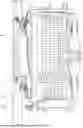
As shown in FIGS. 1 and 2, the existing drum washing machine generally includes an inner drum 300, an outer tub 200, a housing 100, a damping system, a window gasket 500, a machine door 400 and other structures. The outer tub 200 is installed in the housing 100 of the washing machine and supported by the damping system in a vibrating manner, and the inner drum 300 is coaxially sleeved inside the outer tub 200. Motor and other driving devices are installed on the outer tub 200, an output shaft of the motor is connected with the inner drum 300, and is used to drive the inner drum 300 to rotate around the axis, so as to achieve the effect of tumbling and washing the laundry in the inner drum. One end of the outer tub 200 is closed to form an outer tub rear, and the other end is provided with an opening to form an outer tub opening. The outer tub opening is connected with the front panel of the housing 100 via the window gasket 500, so that the gap between the outer tub opening and the front panel of the housing can be closed by the window gasket 500, and the expansion and contraction deformation of the window gasket 500 can be used to prevent the housing 100 from being affected when the outer tub 200 vibrates. In addition, a machine door 400 capable of being closed or opened is installed on the housing 100, and the machine door 400 cooperates with the window gasket 500, so that the machine door 400 being in a closed state can correspondingly close the outer tub opening, and a water-containing chamber is formed in the outer tub 200.
In order to facilitate user to observe the working condition inside the outer tub, an observation window made of transparent glass or other materials is generally provided on the machine door 400, and at least part of the observation window protrudes towards the interior of the outer tub, so that a glass protruding part extending into the hollow area of the window gasket is formed on the machine door. A gap is formed between the glass protruding part and the window gasket 500. However, for the sake of appearance design, the center of the circle where the observation window of some existing drum washing machine is located is generally significantly higher than the center of the circle where the outer tub 200 is located, so there is a relatively large gap between the observation window made of glass and the window gasket 500, and the laundry in the tub may easily fall into the gap.
After falling into the gap, the laundry is clamped by the gap, and the other laundry is still driven to lift by the rotating inner drum 300, so the laundry is caused to be worn, and even to be damaged.
In addition, in order to achieve a vibrating connection with the outer tub opening, the window gasket 500 is generally provided with wrinkles that can generate elastic deformation. The laundry entering in the gap between the observation window made of glass and the window gasket is easily clamped by the wrinkles, which further aggravates the wear of the laundry, and even causes problems such as the motor being unable to drive the inner drum 300 to rotate when too much laundry is clamped.
In view of this, the present invention is provided.
SUMMARY OF INVENTION
An objective of the present invention is to overcome the shortcomings of the prior art and provide a washing machine to prevent laundry from entering the gap between the machine door and the window gasket, thereby reducing in wearing laundry and avoiding the problems such as that the washing machine stops running due to laundry being clamped, and especially preventing laundry in the washing machine from being clamped by the wrinkles of the window gasket.
In order to solve the above technical problem, the basic concept of the technical solutions adopted by the present invention is as follows.
A washing machine, includes: a housing having an opening; an outer tub installed in the housing and having an outer tub opening corresponding to the opening; an inner drum, rotatably installed in the outer tub and having an inner drum opening being a same side with the outer tub opening; a window gasket, of which two ends are respectively connected with the outer tub opening and the opening of the housing to form a laundry loading port for loading or unloading laundry; and a machine door, installed on the housing for opening and closing the laundry loading port. A shielding part is disposed on the outer tub, configured to protrude radially and inward and at least partially located on an inner side of the outer tub opening, and the shielding part is used for shielding a gap between the window gasket and the machine door.
As an embodiment, a glass protrusion extending into the laundry loading port is disposed on the machine door. The shielding part is radially and inward protruded from the outer tub opening, and the shielding part is configured to shield the gap between an outer peripheral side of the glass protrusion and an inner side of the window gasket. Preferably, an extended end of the shielding part is in contact with or close to the outer peripheral side of the glass protrusion, so that the gap between the shielding part and the glass protrusion can be minimized as much as possible on the premise that the glass protrusion is not affected by the vibration of the outer tub, and the shielding part can shield the gap between the window gasket and the glass protrusion to the maximum extent.
As an embodiment, the shielding part is provided with at least one protrusion protruding toward an interior of the outer tub. Preferably, an inner drum is disposed in the outer tub, at least part of the protrusion is configured to extend into the inner drum from an inner drum opening, and the protrusion is spaced apart from an inner side of the inner drum for shielding the gap between the inner drum opening and the outer tub opening without interfering with a rotation of the inner drum.
As an embodiment, a protruding end of the protrusion and an end surface of the glass protrusion of the machine door are in a same vertical plane. Preferably, the protruding end of the protrusion, the end surface of the glass protrusion, and a tub opening flange of the inner drum are all in the same vertical plane.
As an embodiment, a middle of the shielding part is provided with a folded bending part protruding toward the interior of the outer tub, and the folded bending part is as the protrusion.
As an embodiment, two ends of the window gasket have different radial dimensions, a first end with a larger radial dimension is connected with the outer tub opening, and a second end with a smaller radial dimension is connected with the opening on the housing respectively. The shielding part is configured to extend radially and inward from the outer tub opening, and shield the gap that is between the window gasket and the glass protrusion of the machine door and formed by a difference between the radial dimensions of the first end and the second end of the window gasket. Preferably, a radial dimension of an inner periphery of the shielding part is less than or equal to the radial dimension of the first end.
As an embodiment, an axis of the outer tub is extended horizontally, and the shielding part is a plate-like structure extending radially and inward from the inner side of the outer tub opening. The shielding part is configured to extend continuously or intermittently in a circumferential direction of the outer tub opening, and the shielding part is configured to at least cover a lowest part of the outer tub opening. Preferably, at least one shielding part is disposed at the outer tub opening.
As an embodiment, the shielding part is a semicircle arc plate protruding radially from an inner circumferential side toward a center of the outer tub opening, and covering a lower of the outer tub opening. Preferably, a radial protruding height of the semicircle arc plate is gradually decreased from the middle to both ends.
As an embodiment, a front end of the outer tub is composed of a tub opening flange, a circle of bending structure is extended forward from a middle of the tub opening flange, and an inner peripheral wall of the bending structure forms the outer tub opening. A first end of the window gasket is correspondingly sleeved on an outer periphery of the bending structure. An end of the bending structure is provided with an extending rib extending toward an interior the outer tub opening, and the extending rib is as the shielding part.
As an embodiment, a side of the shielding part facing an interior of the tub is provided with a plurality of supporting ribs being protruded, extended radially along the tub opening and arranged at intervals, and ends of the supporting ribs are connected with or close to the inner peripheral wall of the bending structure.
As an embodiment, radial dimension of the outer tub opening is larger than that of the inner drum opening, and the outer tub opening is protruded outward relative to the inner drum opening. The shielding part is disposed on the inner side of the outer tub opening and configured to protrude radially toward the interior of the tub opening, and the shielding part is located outside the inner drum opening. Preferably, a radial dimension of an end of the shielding part is less than the radial dimension of the inner drum opening.
As an embodiment, an end of the shielding part is provided with a protruding part protruding towards an interior of the inner drum, and the protruding part is used for shielding a gap between the shielding part and the inner drum opening in an axial direction. Preferably, at least part of the protruding part is extended into the inner drum opening.
As an embodiment, an outer peripheral wall of the protruding part facing the inner drum opening is configured as an arc surface. Preferably, an outer end surface of the inner drum opening is configured as an arc surface that has a same centre with and different diameter from the arc surface of the outer peripheral wall of the protruding part.
As an embodiment, the shielding part 8 is configured to protrude radially from the inner side towards a center of the outer tub opening, the shielding part extends continuously or discontinuously along the circumference of the outer tub opening, and the shielding part is configured to at least cover the lowest part of the outer tub opening.
As an embodiment, the shielding part is an annular shape extending in a circumferential direction of the outer tub opening, and a radial dimension of an inner circumference of the annular shape is smaller than the radial dimension of the inner circumference of the inner drum opening.
As an embodiment, the window gasket is provided with a protruding rib protruding inward, and a protruding end of the protruding rib is close to or in contact with the shielding part for supporting the extending end of the shielding part.
As an embodiment, the shielding part is integrally with the outer tub.
Through the above-mentioned technical solutions of the present invention, there are the following advantages compared with the prior art.
A shielding part protruding radially and inwardly is disposed at an outer tub opening for shielding the gap between the machine door and the window gasket, so the shielding part is used to prevent laundry in the inner drum of a washing machine from entering the gap between a machine door and a window gasket, especially to prevent laundry from entering wrinkles of the window gasket. Therefore laundry is prevented from being clamped during the running of a washing machine. The shielding part is integrated with the outer tub opening, and an extending end of the shielding part with the properties of being able to generate elastic deformation applies a rebound force to the laundry moving toward the gap between the machine door and the window gasket, thereby the shielding part can drive the laundry to move toward the interior of the inner drum.
In addition, a shielding part radially protruding is disposed at an outer tub opening for shielding the gap between an outer tub opening and an inner drum opening, thereby laundry in the inner drum is prevented from entering the gap, and further effectively prevented from being clamped to cause to happen the problems during the running of a washing machine, such as being worn and even stopping rotating the inner drum.
In order to solve the shortcomings of the prior art, the present invention is to provide a washing machine which prevents laundry from entering in an outer tub from a gap between an inner drum opening and an outer tub opening, and avoids happening the problems such as cause laundry to be clamped, and even to stopping rotating the inner drum of the washing machine. Thereby it is achieved to prevent laundry from being clamped during the washing process of a washing machine.
In order to solve the above technical problem, the basic concept of the technical solutions adopted by the present invention is as follows.
A washing machine, includes: an outer tub having an outer tub opening; and an inner drum, rotatably installed in the outer tub and having an inner drum opening communicating with the outer tub opening. A shielding part is disposed on the outer tub, configured to protrude toward an interior of the outer tub, and used for correspondingly shielding a gap between the inner drum opening and the outer tub opening.
As an embodiment, a radial dimension of the outer tub opening is greater than that of the inner drum opening, and the outer tub opening is configured to protrude outward relative to the inner drum opening. The shielding part is disposed on an inner side of the outer tub opening and configured to extend radially toward an interior of the outer tub opening. The shielding part is located on outside of the inner drum opening, and at least part of the shielding part is located in an inner side of the inner drum opening.
As an embodiment, a radial dimension of an end of the shielding part is smaller than the radial dimension of the inner drum opening.
As an embodiment, the shielding part is configured to extend from the inner side toward a center of the outer tub opening, and at least part of the shielding part in an extending direction is inclined toward an interior of the inner drum.
As an embodiment, an end of the shielding part is provided with a protruding part protruding towards an interior of the inner drum, and the protruding part is used for shielding a gap between the shielding part and the inner drum opening in an axial direction. Preferably, at least part of the protruding part is extended into the inner drum opening.
As an embodiment, an outer peripheral wall of the protruding part facing the inner drum opening is configured as an arc surface. Preferably, an outer end surface of the inner drum opening is configured as an arc surface that has a same center with and different diameter from the arc surface of the outer peripheral wall of the protruding part.
As an embodiment, the protruding part and the inner drum opening are arranged at intervals.
As an embodiment, protruding parts are the disposed on the end of the shielding part, and the protruding parts are configured to extend circumferentially along the outer tub opening and are arranged at intervals in a radial direction of the outer tub opening.
As an embodiment, protruding heights of the protruding parts are gradually decreased in a direction toward the outer peripheral side of the outer tub opening.
As an embodiment, the shielding part is configured to protrude radially from the inner side towards a center of the outer tub opening, the shielding part is configured to extend continuously or discontinuously along the circumference of the outer tub opening, and the shielding part is configured to at least cover the lowest part of the outer tub opening.
As an embodiment, the shielding part is an annular shape extending in a circumferential direction of the outer tub opening, and a radial dimension of an inner circumference of the annular shape is smaller than the radial dimension of the inner circumference of the inner drum opening.
As an embodiment, the front end of the outer tub is formed by a tub opening flange, and the middle of the tub opening flange has a circle of cylindrical bending structure extending forward and protruding. The inner peripheral side of the bending structure 10 surrounds the outer tub opening; the first end of the window gasket is sleeved corresponding to the outer periphery of the bending structure; the end of the bending structure is provided with a circle of annular extending ribs extending inward from the tub opening, and the extending ribs constitute the shielding part.
As an embodiment, the side of the shielding part facing the inside of the tub is provided with a plurality of protruding supporting ribs extending radially along the tub opening and arranged at intervals. The ends of the supporting ribs are connected to or arranged close to the inner side wall of the bending structure.
As an embodiment, at least part of the shielding part protrudes radially inward from the first end of the window gasket, and the second end of the window gasket is connected to the housing to form a clothing treatment opening for taking and placing laundry into the tub; a machine door is installed on the housing, and the machine door corresponds to opening and closing the clothing loading opening; the machine door is provided with a glass protruding part extending into the clothing loading opening, and the shielding part shields the gap between the inner side of the window gasket and the glass protruding part.
As an embodiment, the shielding part is integrally provided with the outer tub; or, the shielding part is an independent part fixedly installed on the outer tub.
Through applying the above technical solutions of the present invention, there are the following advantages compared with the prior art.
A shielding part radially protruding is disposed at an outer tub opening for shielding the gap between an outer tub opening and an inner drum opening, thereby laundry in the inner drum is prevented from entering the gap, and further effectively prevented from being clamped to cause to happen the problems during the running of a washing machine, such as being worn and even stopping rotating the inner drum.
In the present invention, the shield part has a simple structure and significant effect, and is suitable for promotion and application.
The embodiments of the present invention are further described in detail below in conjunction with the accompanying drawings.
BRIEF DESCRIPTION OF THE DRAWINGS
Accompanying drawings, constituting a part of the present invention, are used for providing a further understanding of the present invention, illustrative embodiments of the present invention and description thereof are used for explaining the present invention, and do not constitute an improper limitation on the present invention. Apparently, the accompanying drawings in the following description are only some embodiments, for those ordinarily skilled in the art, on the premise of no creative labor, other accompanying drawings can further be obtained from these accompanying drawings. In the Figures:
FIG. 1 is a structural diagram of a section of a washing machine in the prior art;
FIG. 2 is an enlarged structural diagram of point A in FIG. 1;
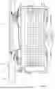
FIG. 3 is a structural diagram of a section of a washing machine in one embodiment;
FIG. 4 is an enlarged structural diagram of point B in FIG. 3;
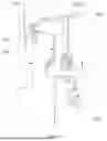
FIG. 5 is a structural diagram of a tub opening flange of an outer tub in one embodiment;
FIG. 6 is a structural diagram of section C-C in FIG. 5;
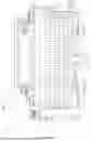
FIG. 7 a structural diagram of a section of a washing machine in one embodiment;
FIG. 8 is an enlarged structural diagram of point B in FIG. 7;
FIG. 9 is a structural diagram of a section of a window gasket in one embodiment;
FIG. 10 is a structural diagram of section C-C in FIG. 9.
Description of the main components in the figures: 100. Housing; 200. Outer tub; 300. Inner drum; 400. Machine door; 500. Window gasket; 1. window gasket body; 2. Wrinkle; 3. First end; 4. Second end; 5. Blocking part; 7. Shielding part; 9. Supporting rib; 10. Bending structure; 11. Water outlet; 21. Outer tub opening; 31. Inner drum opening; 41. Glass protrusion; 71. Protrusion; 81. Protruding part; 82. Arc surface.
It should be noted that these drawings and the description are not intended to limit the scope of the present invention in any way, but rather to illustrate the concept of the present invention for those skilled in the art by referring to specific embodiments.
DETAILED DESCRIPTION
In order to make objects, technical solutions and advantages of the embodiments of the present invention clearer, the solutions in the embodiments are clearly and completely described as follows in combination with accompanying drawings in the embodiments of the present invention. The following embodiments are used for illustrating the present invention, rather than limiting the scope of the present invention.
In the description of the present invention, it should be noted that, the orientation or positional relationship indicated by such terms as “up”, “down”, “front”, “rear”, “left”, “right”, “vertical”, “inner” and “outer” is the orientation or positional relationship based on the accompanying drawings. Such terms are merely used for conveniently and simplified describing the present invention, rather than indicating or implying that the device or element referred to must be located in a certain orientation or must be constructed or operated in a certain orientation. Therefore, the terms cannot be understood as a limitation to the present invention.
In the description of the present invention, it should be noted that, unless otherwise stipulated and defined definitely, such terms as “installed”, “connected” and “in connection” should be understood in their broad sense, e.g., the connection can be a fixed connection, a detachable connection or an integral connection; can be mechanical connection or electrical connection; and can be direct connection or can be indirect connection through an intermediate. For those skilled in the art, specific meanings of the above terms in the present invention can be understood according to specific conditions.
The invention is in detail described in the following embodiments.
As shown in FIGS. 3 to 10, a washing machine includes: a housing 100 having an opening; an outer tub 200 installed in the housing 100 and having an outer tub opening 21 corresponding to the opening; a window gasket 500, of which two ends are respectively connected with the outer tub opening 21 and the opening of the housing 100 to form a laundry loading port for loading or unloading laundry; and a machine door 400 installed on the housing 100 for opening and closing the laundry loading port. A shielding part 7 is disposed on the outer tub 200, configured to protrude radially and inward, and at least partially located on an inner side of an outer tub opening 21. The shielding part 7 is used for shielding a gap between the window gasket 500 and the machine door 400.
By arranging the shielding part protruding radially and inward at the outer tub opening, the shielding part is used to shield the gap between the machine door and the window gasket, so that the laundry in the inner drum of the washing machine is prevented from entering the gap between the machine door and the window gasket, especially prevented from entering the wrinkle of the window gasket. Thereby the laundry is prevented from being clamped during the running of the washing machine. The shielding part is disposed at the outer tub opening, and an extended end of the shielding part with the properties of being able to generate elastic deformation applies a rebound force to the laundry moving toward the gap between the machine door and the window gasket, thereby the shielding part can drive the laundry to move toward the interior of the inner drum.
In the embodiment of the present invention, a glass protrusion 41 extending into the laundry loading port is disposed on the machine door 400, the shielding part 7 is radially and inward protruded from the outer tub opening 21, and the shielding part 7 is configured to shield the gap between the outer peripheral side of the glass protrusion 41 and the inner peripheral side of the window gasket 500. Preferably, the extended end of the shielding part 7 is in contact with or close to the outer peripheral side of the glass protrusion 41, so that the shielding part can shield most space of the gap between the protrusion of the machine door and the window gasket, thereby effectively preventing the laundry in the inner drum from entering the gap. Preferably, the extended end of the shielding part 7 is configured to be close to the outer peripheral side of the glass protrusion 41, so that the gap between the shielding part 7 and the glass protrusion 41 can be minimized as much as possible on the premise that the glass protrusion 41 is not affected by the vibration of the outer tub, and the shielding part 7 can shield the gap between the window gasket 500 and the glass protrusion 41 to the maximum extent. Specifically, the above arrangement of being close to the outer peripheral side of the glass protrusion is as follows: there is no interference such as relative collision between the shielding part 7 and the glass protrusion 41 when the outer tub is caused to vibrate during the operation of the washing machine, and the gap needs to be reserved between the shielding part 7 and the glass protrusion 41. The gap is the maximum displacement of the outer tub opening in the vibration of the outer tub, and the spacing where the extended end of the shielding part 7 is close to the outer peripheral side of the glass protrusion 41 is as the above-mentioned maximum displacement of the outer tub opening in the vibration of the outer tub.
In the embodiment of present invention, an inner drum 300 is disposed inside the outer tub 200, and at least part of a protrusion 71 is configured to extend into the inner drum 300 from an inner drum opening 31. The protrusion 71 is spaced apart from an inner side of the inner drum 300, for shielding the gap between the inner drum opening 31 and the outer tub opening 21, so that the inner drum is not in contact with and affected by the protrusion during the rotating of the inner drum due to the gap.
In the embodiment of the present invention, the shielding part 7 is provided with at least one protrusion 71 protruding toward the interior of the outer tub 200, so as to change an outer contour of the shielding part facing the interior of the tub by using the protrusion. Thereby the moving mode of the laundry can be changed by the protrusion, and then the protrusion can push the laundry back into the inner drum.
In the embodiment of the present invention, a protruding end of the protrusion 71 and an end surface of the glass protrusion 41 of the machine door 400 are in the same vertical plane. Preferably, the protruding end of the protrusion 71, the end surface of the glass protrusion 41 of the machine door, and a tub opening flange are all in the same vertical plane, so that the protrusion is fully located in the gap between the machine door and the window gasket, used for effectively shielding the gap between the two. The protruding end of the protrusion is configured to flush with the end face of the flange of the inner drum opening, so the protrusion of the outer tub opening does not extend into the inner drum, and is prevented from interfering in the lifted move of the laundry inside the inner drum. Thereby it is improved in the washing effect of the washing machine.
In the embodiment of the present invention, the middle part of the shielding part 7 is provided with a folded bending part protruding toward the interior of the outer tub, and the folded bending part is as the protrusion 71. In the embodiment of the present invention, the protrusion 71 is formed by bending a part of the shielding part 7 being the plate structure, so that the protrusion 71 is a folded structure being hollow inside. When the protrusion is squeezed by the laundry, the protrusion can be driven to generate deformation by using its own folded structure, and the deformation restoring force is used to drive the laundry to move back into the inner drum.
In the embodiment of the present invention, the two ends of the window gasket 200 have different radial dimensions, a first end 3 with a larger radial dimension is connected with the outer tub opening 21, and a second end 4 with a smaller radial dimension is connected with the opening on the housing 100. The shielding part 7 is configured to extend radially and inward from the inner drum opening 21, and shield the gap that is between the window gasket 500 and the glass protrusion 41 of the machine door 400 and formed by the difference between the radial dimensions of the first end 3 and the second end 4 of the window gasket 500. Preferably, the radial dimension of the inner circumference of the shielding part 7 is less than or equal to the radial dimension of the first end 3, so as to ensure that the shielding part can shield at least part of the gap between the window gasket and the machine door. Thereby the shielding part prevents the laundry in the inner drum from entering the gap through the tub opening.
In the embodiment of the present invention, an axis of the outer tub 200 is extended horizontally, and the shielding part 7 is a plate-like structure extending radially and inward from the inner side of the outer tub opening 21. The shielding part 7 is configured to extend continuously or intermittently along a circumferential direction of the outer tub opening, and the shielding part 7 covers at least the lowest part of the outer tub opening 21. Preferably, at least one shielding part 7 is disposed at the outer tub opening 21. By arranging the shielding part at least at the lowest part of the window gasket, a position at the lowest part of the window gasket where the laundry is most likely to fall into the gap is shielded. Thereby it is improved in effect of the shielding part in preventing the laundry from entering the gap between the window gasket and the machine door.
In the embodiment of the present invention, the shielding part 7 is a semicircle arc plate protruding radially from the inner circumferential side toward the center of the outer tub opening 21 and covering the lower of the outer tub opening 21. Preferably, a radial protruding height of the semicircle arc plate is gradually decreased from the middle to both ends. By setting the shielding part as a semicircle arc shape, the shielding part can shield the lower of the tub opening, so that it is effectively avoided occur the situation that the laundry enters the gap between the machine door and the window gasket during the falling process. Since the laundry does not move forward in moving in the upper of the inner drum, the stability of moving the laundry is poor in the upper of the inner drum due to gravity, so the probability that the laundry is clamped in the gap between the upper of the machine door and the window gasket is extremely low. Due to the absence of the shielding part in the upper, it can be effectively reduced in the production cost of the outer tub, and the shielding part can be also used to quickly assemble and position the outer tub. Of course, in the embodiment of the present invention, the shielding part 7 can also be set as a ring-shaped structure, which can cause to reduce the irregularity of the outer tub opening, and also simplify the processing technology of the outer tub and reduce the wear of the outer tub on the laundry.
In the embodiment of the present invention, the front end of the outer tub 200 is composed of a tub opening flange, and a circle of bending structure 10 is extended forward from the middle of the tub opening flange, and the inner peripheral wall of the bending structure 10 forms the outer tub opening 21. The first end 3 of the window gasket 500 is correspondingly sleeved on the outer periphery of the bending structure 10. An end of the bending structure 10 is provided with an extending rib extending toward the interior of the outer tub opening 21, and the extending rib is in arc-shaped or arc-shaped, which constitutes the shielding part 7. The middle area of the radial orientation of the extending rib is provided with a protrusion 71 being circumferentially extended, and the protrusion 71 is formed by folding the extending rib itself and extended toward the interior of tub. A part of the extending rib on the outer peripheral side of the protrusion 71 is a slope being gradually inclined toward the interior of the tub from the outer periphery to the inner periphery, so as to increase the elastic restoring force of the extending rib. Thereby it is increased in the force of pushing the laundry back toward the interior of the inner drum. Further preferably, the extending rib on the outer peripheral side of the protrusion 71 is a wave slope gradually inclined first toward the outside of the tub and then toward the interior of the tub, from the outer periphery to the inner periphery, so as to further improve the structural strength of the shielding part itself and effectively increase its elastic restoring force toward the interior of the tub.
In the embodiment of the present invention, a side of the shielding part 7 facing the interior of the tub is provided with a plurality of supporting ribs 9 being protruded, extended radially along the tub opening and arranged at intervals, and the ends of the supporting ribs 9 are connected with or close to the inner peripheral wall of the bending structure 10. The ends of the supporting ribs 9 are connected with the bending structure 10, so that there is a supporting force to the bending structure at the connection. When the ends of the supporting ribs 9 are arranged close to the bending structure, the interval distance between them is as small as possible and generally less than the maximum deformation amount of the shielding part 7. Therefore, when the shielding part 7 is vibrated and deformed by an external force, the ends of the supporting ribs 9 are in contact with the bending structure, further the supporting ribs 9 provide sufficient supporting force to the shielding part 7, and it is avoided to cause the situations such as the shielding part 7 is deformed too much and unable to reset.
Preferably, the supporting ribs 9 are arranged on the outer periphery of the protrusion 71, and the protruding height of the supporting ribs 9 is lower than the protruding height of the protrusion 71 and lower than the extending distance of the bending structure 10 constituting the outer tub opening 21, so as to not cause the problem that the supporting ribs are protruded into the tub and interfere with the rotating inner drum. Further preferably, the supporting ribs 9 are arranged on a part of the inner wall of the extending rib inclined toward the outside of the tub and on the outer periphery of the protrusion 71. The supporting rib 9 is configured to extend radially along the window gasket with a shape of ring, and a width of the extending end of the supporting rib is much smaller than the width at the connection with the extending rib.
Another embodiment in the present invention is described.
As shown in FIGS. 7 to 10, a washing machine of the embodiment of the present includes: a housing 100 having an opening; an outer tub 200 installed in the housing 100 and having an outer tub opening 21 corresponding to the opening; a window gasket 500, of which two ends are respectively connected with the outer tub opening 21 and the opening of the housing 100 to form a laundry loading port for loading or unloading laundry; an inner drum 300 rotatably disposed in the outer tub 200; and a machine door 400 installed on the housing 100 for opening and closing the laundry loading port. The outer tub opening 21 and an inner drum opening 31 are arranged on a same side. A shielding part 7 is disposed on the outer tub 200, configured to protrude inward, and used for shielding a gap between the inner drum opening 31 and the outer tub opening 21.
By arranging the shielding part protruding radially at the outer tub opening, the shielding part is used to shield the gap between the outer tub opening and the inner drum opening, so that the laundry in the inner drum is prevented from entering the gap. Thereby it is effectively avoided the problems, such as that the laundry is clamped and worn during the running of the washing machine, and even the inner drum stops rotating.
In embodiment of the present invention, a radial dimension of the outer tub opening 21 is larger than that of the inner drum opening 31, and the outer tub opening 21 is protruded outward relative to the inner drum opening 31. The shielding part 7 is disposed on the inner side of the outer tub opening 21 and configured to protrude radially toward the interior of the tub opening, and the shielding part 7 is located outside the inner drum opening 31. At least part of the shielding part 7 is located in the inner side of the inner drum opening 31, so that part of the shielding part is located at the gap between the inner drum opening and the outer tub opening, for effectively shielding the gap between the inner drum opening and the outer tub opening by the shielding part.
As shown in FIGS. 7 to 10, in embodiment of the present invention, a radial dimension of the end of the shielding part 7 is smaller than the radial dimension of the inner drum opening 31, so that at least part of the shielding part can be located in the inner side of the inner drum opening, and the shielding part is used to effectively shield the gap between the inner drum and the outer tub.
As shown in FIGS. 7 to 10, in the embodiment, at least part of the shielding part 7 near the extending end is an inclined surface inclining toward the inside of the tub, so that at least part of the shielding part 7 can be extended into the gap between the outer tub opening 21 and the inner drum opening 31, to effectively shielding the gap between the inner drum and outer tub.
In the embodiment, the end of the shielding part 7 is provided with a protruding part 81 protruding toward the interior of the inner drum 300. The protruding part 81 is used for shielding the gap between the shielding part 7 and the inner drum opening 31 an axial direction. Preferably, at least part of the protruding part 81 is extended into the inner drum opening 31 to improve the effect of the shielding part shielding the gap between the inner drum and the outer tub.
As shown in FIGS. 7 to 10, in the embodiment, the outer peripheral wall of the protruding part 81 facing the inner drum opening 31 is configured as an arc surface 82. Preferably, the outer end surface of the inner drum opening 31 is configured as an arc surface that has a same center with and different diameter from the arc surface 82 of the outer peripheral wall of the protruding part 81, so that the laundry is guided by the above-mentioned arc surfaces, and further the laundry is prevented from being clamped between the inner drum and the outer tub, especially the clamped laundry is avoided being damaged. Preferably, the protruding part 81 is a conical protrusion of which the radial dimension is configured to gradually narrow in an extending direction. The inner peripheral side of the protruding part 81 near an inside of a window gasket body 1 is a smoothly arc surface, and the outer peripheral side of the protruding part 81 away from the inside of the window gasket body 1 is the above-mentioned arc surface with gradually increasing curvature, so that the radial dimension of the protruding part 81 in a radial direction of the window gasket body 1 is gradually decreased. Thereby it is decreased in the interference of the protruding part 81 on the rotation of the inner drum 300.
In the embodiment, the shielding part 7 is configured to protrude radially from the inner peripheral side toward a center of the outer tub opening 21. The shielding part 7 is extended continuously or non-continuously along the circumferential direction of the outer tub opening 21. The shielding part 7 is configured to at least cover the lowest part of the outer tub opening 21. Preferably, the shielding part 7 is a ring extending along the circumference of the outer tub opening 21, and a radial dimension of an inner periphery of the ring is smaller than a radial dimension of an inner periphery of the inner drum opening 31, so that the shielding part is extended along the outer tub opening. The shielding part can effectively prevent laundry in all directions from entering the gap between the inner drum opening and the outer tub opening.
As shown in FIGS. 7 to 10, in the embodiment, a front end of the outer tub 200 is composed of a tub opening flange, and a circle of bending structure 10 is extended forward from the middle of the tub opening flange, and the inner peripheral wall of the bending structure 10 forms the outer tub opening 21. The first end 3 of the window gasket 500 is correspondingly sleeved on the outer periphery of the bending structure 10. An end of the bending structure 10 is provided with an extending rib extending toward the interior of the outer tub opening 21 and forming a ring, and the extending rib constitutes the shielding part 7.
In the embodiment, a side of the shielding part 7 facing the interior of the tub is provided with a plurality of supporting ribs 9 being protruded, extended radially along the tub opening and arranged at intervals. The ends of the supporting ribs 9 are connected with or close to the inner peripheral wall of the bending structure 10.
In the present embodiment, at least part of the shielding part 7 is protruded radially and inward beyond the first end 3 of the window gasket 500, and the second end 4 of the window gasket 500 is connected with the housing 100, to form a laundry loading port for loading or unloading laundry. A machine door 400 is installed on the housing 100 for opening and closing the laundry loading port. A glass protrusion 41 extending into the laundry loading port is disposed on the machine door 400, and the shielding part 7 is configured to shield the gap between the inner side of the window gasket 500 and the glass protrusion 41.
In the embodiment, the shielding part 7 can be integrated with both the protruding part 81 and the protrusion 71, so that the shielding part 7 can simultaneously prevent laundry in the inner drum from entering the gap between the inner drum opening and the outer tub opening and the gap between the window gasket and the machine door, and laundry is effectively avoided being clamped during a washing process of a washing machine. The protruding part 81 and the protrusion as individual components can be arranged in a staggered manner, or the protruding part 81 can be a single part on the shielding part 7, or the protruding part 81 and the protrusion can be integrated on the same part of the shielding part 7 (not indicated in the figures).
In the embodiment, in order to improve the structural strength of the window gasket 500, a plurality of reinforcing protrusions being radially extended and spaced apart are disposed on the outer peripheral side of the window gasket body 1. Each of the reinforcing protrusions is used to change the thickness of the window gasket body 1 in the circumferential direction, so that the window gasket body 1 is not easily deformed by compression in the circumferential direction.
As shown in FIGS. 3 to 10, the window gasket 500 includes an annular window gasket body 1. A connection of the first end 3 of the window gasket body 1 is as a first part being no taper or a small taper. The radial dimension of the first part is gradually decreased or unchanged from the first end toward the inside. A connection of the second end 4 of the window gasket body 1 is as a second part being no taper or a small taper. The radial dimension of the second part is gradually decreased or unchanged from the second end toward the inside. The connections of the first part and the second part are respectively an annular shape being vertically extended. The inner and outer sides of the annular connection are connected with the first part and the second part respectively. The annular connection is provided with a plurality of wrinkles 2, so that the window gasket 1 can realize telescopic deformation by using the wrinkles 2.
A second connecting structure disposed at the second end 4 of the window gasket body 1 is an installation rib protruding from the end toward the inner peripheral side and the outer peripheral side respectively. The installation rib on the outer peripheral side is connected with the inner side of the housing 100 of the washing machine, and the installation rib on the outer peripheral side is in close contact with the outer peripheral side of the machine door 400 to achieve sealing after the machine door 400 is closed. A first connecting structure disposed at the first end 3 of the window gasket body 1 is an installation rib protruding from the end toward the outer peripheral side. The installation rib on the outer peripheral side is connected with the outer side surface of the outer tub opening 21 of the washing machine.
In the embodiment, the opening of the housing 100 of the washing machine is provided with a bending part that is extended outward from the housing and bent radially and outward. The installation rib disposed on the outer peripheral side of the second end 4 of the window gasket body 1 is sleeved on the outer wall of the bending part, and at least one ring of steel wire or the like is wound around the sleeve joint, so that the second end 4 of the window gasket body 1 is fixedly connected with the housing 100. Preferably, in order to reduce the protruding height on the outside of the housing, a ring of groove being inwardly recessed can be arranged around the opening of the housing 100. The inner peripheral side of the groove forms an opening, and the above bending part is disposed on the inner peripheral side of the groove, so that the installation rib disposed on the outer peripheral side of the second end of the window gasket body 1 is located on the outside of the housing and is correspondingly sleeved on the outer wall of the bending part.
A bending part that is extended toward the outside of the tub and bent radially and outward is disposed at the bending structure 10 of the outer tub opening 21. The installation rib disposed on the outer peripheral side of the first end 3 of the window gasket body is arranged on the outer wall of the bending part provided on the bending structure 10 of the outer tub opening 21, and at least one ring of steel wire or the like is wound around the sleeve joint, so that the first end 3 of the window gasket body 1 is fixedly connected with the outer tub opening 21.
In addition, in order to improve the connection reliability between the window gasket body 1 and the outer tub opening, the installation rib disposed on the outer peripheral side of the first end 3 of the window gasket body 1 is in close contact with at least part of the outer surface of the shielding part, so as to increase the contact area between the window gasket body and the outer tub opening and improve the installation stability of the window gasket.
In the embodiment, a row of water outlets 11 is also formed at a bottom of the window gasket body 1. The water outlets 11 are used for communicating the lowest point of the wrinkle 2 at the outermost periphery of the window gasket body 1 with the outside, so that water remained in the wrinkle 2 can flow into the outer tub 200 of the washing machine through the water outlets 11, and residual water is prevented from remaining inside the window gasket 500. The water outlets 11 are formed at the connection between the first connecting structure provided at the first end 3 of the window gasket body 1 and the first part, that is, at the wrinkle 2 outwardly protruding formed by the first part and the connecting part.
The above descriptions are only preferred embodiments of the present application, and do not limit the present application in any form. Although the present application has been disclosed as above with preferred embodiments, it is not intended to limit the present application. Without departing from the scope of the technical solution of the present invention, anyone skilled in the art of the invention can use the content of the invention to make some changes or modify embodiments into equivalent embodiments with equivalent effects. Any simple modifications, equivalent changes and modifications made to the above embodiments still fall within the scope of the solutions of the present invention.
Claims
1. A washing machine, including:
a housing, having an opening;
an outer tub, installed in the housing (100) and having an outer tub opening corresponding to the opening;
a window gasket, of which two ends are respectively connected with the outer tub opening and the opening of the housing to form a laundry loading port for loading or unloading laundry; and
a machine door, installed on the housing for opening and closing the laundry loading port;
wherein:
a shielding part is disposed on the outer tub, configured to protrude radially and inward, and at least partially located on an inner side of the outer tub opening, and the shielding part is used for shielding a gap between the window gasket and the machine door.
2. The washing machine according to claim 1, wherein, a glass protrusion extending into the laundry loading port is disposed on the machine door; and
the shielding part is radially and inward protruded from the outer tub opening, and the shielding part is configured to shield the gap between an outer peripheral side of the glass protrusion and an inner side of the window gasket.
3. (canceled)
4. The washing machine according to claim 1, wherein, the shielding part is provided with at least one protrusion protruding toward an interior of the outer tub.
5. The washing machine according to claim 4, wherein, an inner drum is disposed in the outer tub,
at least part of the protrusion is configured to extend into the inner drum from an inner drum opening, and the protrusion is spaced apart from an inner side of the inner drum for shielding the gap between the inner drum opening and the outer tub opening without interfering with a rotation of the inner drum.
6. The washing machine according to claim 4, wherein, a protruding end of the protrusion and an end surface of the glass protrusion of the machine door are in a same vertical plane.
7. The washing machine according to claim 4, wherein, a middle of the shielding part is provided with a folded bending part protruding toward the interior of the outer tub, and the folded bending part is as the protrusion.
8. (canceled)
9. The washing machine according to claim 1, wherein, an axis of the outer tub is extended horizontally, and the shielding part is a plate-like structure extending radially and inward from the inner side of the outer tub opening;
the shielding part is configured to extend continuously or discontinuously in a circumferential direction of the outer tub opening; and
the shielding part is configured to at least cover a lowest part of the outer tub opening.
10. The washing machine according to claim 9, wherein: the shielding part is a semicircle arc plate protruding radially from an inner circumferential side toward a center of the outer tub opening, and covering a lower of the outer tub opening;
a radial protruding height of the semicircle arc plate is gradually decreased from a middle to both ends.
11. The washing machine according to claim 1, wherein, a front end of the outer tub is composed of a tub opening flange, a circle of bending structure is extended forward from a middle of the tub opening flange, and an inner peripheral wall of the bending structure forms the outer tub opening;
a first end of the window gasket is correspondingly sleeved on an outer periphery of the bending structure; and
an end of the bending structure is provided with an extending rib extending toward an interior the outer tub opening, and the extending rib is as the shielding part.
12. The washing machine according to claim 11, wherein, a side of the shielding part facing an interior of the outer tub is provided with a plurality of supporting ribs being protruded, extended radially along the outer tub opening and arranged at intervals, and ends of the supporting ribs are connected with or close to the inner peripheral wall of the bending structure.
13. (canceled)
14. The washing machine according to claim 1, wherein: the window gasket is provided with a protruding rib protruding inward, and a protruding end of the protruding rib is close to or in contact with the shielding part for supporting the extending end of the shielding part.
15. (canceled)
16. The washing machine according to claim 1, including:
an inner drum, rotatably installed in the outer tub and having an inner drum opening communicating with the outer tub opening;
wherein, a shielding part is disposed on the outer tub, configured to protrude toward an interior of the outer tub, and used for correspondingly shielding a gap between the inner drum opening and the outer tub opening.
17. The washing machine according to claim 16, wherein, a radial dimension of the outer tub opening is greater than that of the inner drum opening, and the outer tub opening is configured to protrude outward relative to the inner drum opening;
a shielding part is disposed on an inner side of the outer tub opening and configured to extend radially toward an interior of the outer tub opening; and
the shielding part is located on outside of the inner drum opening, and at least part of the shielding part is located in an inner side of the inner drum opening.
18. (canceled)
19. The washing machine according to claim 16, wherein, the shielding part is configured to extend from an inner side toward a center of the outer tub opening, and at least part of the shielding part in an extending direction is inclined toward an interior of the inner drum.
20. The washing machine according to claim 16, wherein, an end of the shielding part is provided with a protruding part protruding towards an interior of the inner drum, and the protruding part is used for shielding a gap between the shielding part and the inner drum opening in an axial direction.
21. The washing machine according to claim 20, wherein, an outer peripheral wall of the protruding part facing the inner drum opening is configured as an arc surface;
an outer end surface of the inner drum opening is configured as an arc surface that has a same center with and different diameter from the arc surface of the outer peripheral wall of the protruding part.
22. The washing machine according to claim 21, wherein, the protruding part and the inner drum opening are arranged at intervals.
23. The washing machine according to claim 17, wherein, protruding parts are the disposed on the end of the shielding part, and the protruding parts are configured to extend circumferentially along the outer tub opening and are arranged at intervals in a radial direction of the outer tub opening.
24. The washing machine according to claim 23, wherein, protruding heights of the protruding parts are gradually decreased in a direction toward the outer peripheral side of the outer tub opening.
25. The washing machine according to claim 16, wherein, the shielding part is configured to protrude radially from the inner peripheral side towards a center of the outer tub opening;
the shielding part is extended continuously or discontinuously along a circumferential direction of the outer tub opening; and
the shielding part is configured to at least cover a lowest part of the outer tub opening.
26. (canceled)
Images & Drawings included:


Sources:
- United States Patent and Trademark Office - verify current appl. status at the USPTO↗
Similar patent applications:
- » 20190040564
Method for monitoring water consumption of washing machine, washing machine, and washing machine system - » 20190194854
Counterweight of washing machine, washing machine, and counterweighting method for washing machine - » 20110120193
Bush member for rotating shaft of washing machine, washing machine having the bush member and manufacturing method of the bush member and the washing machine - » 20090301142
Pulley electric motor for a washing machine, actuation system for a washing machine and washing machine - » 20200277720
Washing machine receptacle, washing machine and method for operating a washing machine - » 20100050702
Stator for BLDC motor and BLDC motor having the stator, power transmission device for washing machine, driving device for washing machine and full automatic washing machine using the same - » 20130042655
BRUSHLESS MOTOR FOR WASHING MACHINE, DRUM-TYPE WASHING MACHINE PROVIDED WITH SAME AND MANUFACTURING METHOD OF BRUSHLESS MOTOR FOR WASHING MACHINE - » 18244129
Gas heating system for a parts washing machine, and to the method of converting an electric parts washing machine to a gas parts washing machine - » 20180363217
WALL-MOUNTED WASHING MACHINE, DETERGENT CONTAINER OF WALL-MOUNTED WASHING MACHINE, AND FRONT PANEL OF WALL-MOUNTED WASHING MACHINE - » 20150275414
Control method for washing machine, washing machine
Recent applications in this class:
- » 20260110128 2026-04-23
DEFLECTOR ASSEMBLY FOR LAUNDRY APPLIANCE - » 20260092408 2026-04-02
LAUNDRY APPLIANCE WITH A DEFLECTOR - » 20260043185 2026-02-12
GASKET AND WASHER INCLUDING THE SAME - » 20250122661 2025-04-17
DOOR GASKET ASSEMBLY FOR A WASHING MACHINE APPLIANCE - » 20240417908 2024-12-19
LAUNDRY TREATING APPARATUS - » 20240218583 2024-07-04
LAUNDRY APPLIANCE WITH A DEFLECTOR - » 20230272570 2023-08-31
Gasket for washing machines and washing machine including this gasket - » 20230265594 2023-08-24
WASHING MACHINE - » 20230151531 2023-05-18
Washing machine - » 20230037214 2023-02-02
Washing machine
Recent applications for this Assignee:
- » 20260110132 2026-04-23
AUTOMATIC DISPENSING DEVICE, CONTROL METHOD AND MULTI-DRUM WASHING MACHINE - » 20260110132 2026-04-23
AUTOMATIC DISPENSING DEVICE, CONTROL METHOD AND MULTI-DRUM WASHING MACHINE - » 20260043191 2026-02-12
LAUNDRY TREATMENT APPARATUS - » 20260043190 2026-02-12
CLOTHES TREATMENT APPARATUS - » 20260028764 2026-01-29
Filter module, filter module control method and washing equipment - » 20260028764 2026-01-29
Filter module, filter module control method and washing equipment - » 20250361669 2025-11-27
DOUBLE-PUMP ASSEMBLY AND CLOTHES TREATMENT APPARATUS HAVING SAME - » 20250305203 2025-10-02
WASHING APPARATUS, SWITCHING DEVICE AND CONTROL METHOD OF WASHING APPARATUS - » 20250257516 2025-08-14
WASHING APPARATUS - » 20250230599 2025-07-17
FOAM LOCAL CLEANING DEVICE AND WASHING MACHINE