Firearm Suppressor with Low Signature Ventilation
US20260118084A1
2026-04-30
19/085,822
2025-03-20
Smart Summary: A firearm suppressor is designed to reduce the noise of gunshots. It has a tubular shape with a back end that attaches to the gun barrel and a front end where the bullet exits. Inside, there is an expansion chamber that helps slow down and cool the gases from the shot. The suppressor also features special passages that allow the gases to move in a controlled way, reducing sound further. Overall, this design aims to make shooting quieter while maintaining effectiveness. 🚀 TL;DR
Abstract:
A suppressor comprised of a tubular body, a rear end with a barrel attachment facility and a forward end defining a bullet exit aperture in a lateral aperture of the body proximate to an intermediate portion. A rear portion of the body defines an expansion chamber, with an interior tube concentric with the body and a rear tube end spaced apart from the attachment facility. A gas transmission facility is forward of the expansion chamber defining a plurality of helical passages encircling a rear portion of the tube and each have a rear opening, communicating with the expansion chamber, and a forward end communicating with the intermediate interior portion of the body. A gas transmission element forward of the intermediate portion surrounds the tube, and an articulated passage with an entrance communicating with the intermediate portion of the body and extending forward proximate the forward end of the body.
Applicant:
Interested in similar patents?
Get notified when new applications in this technology area are published.
Classification:
F41A21/30 » CPC main
Barrels; Gun tubes; Muzzle attachments; Barrel mounting means Silencers
Description
CROSS-REFERENCE TO RELATED APPLICATIONS
This application claims the benefit of U.S. Provisional Patent Application No. 63/567,675, filed on Mar. 20, 2024, entitled “FIREARM SUPPRESSOR WITH LOW SIGNATURE VENTILATION”, which is hereby incorporated by reference in its entirety for all that is taught and disclosed therein.
FIELD OF THE TECHNOLOGY
The present disclosure relates to firearms, namely suppressors.
BACKGROUND AND SUMMARY
The “Firearm Suppressor with Low Signature Ventilation” addresses the pressing need for advanced firearm suppressor technology in today's firearms industry. Conventional suppressor designs often encounter challenges related to gas flow dynamics, resulting in suboptimal noise reduction and potential performance limitations. The above disadvantages are addressed by a suppressor which is comprised of a tubular body, a rear end with a barrel attachment facility and a forward end defining a bullet exit aperture. The rear portion of the body defines the expansion chamber, with an interior tube concentric with the body and a rear tube end spaced apart from the attachment facility. The suppressor has a gas transmission facility forward of the expansion chamber and defines a plurality of helical passages encircling a rear portion of the tube. The helical passages each have a rear opening, communicating with the expansion chamber, and a forward end communicating with an intermediate interior portion of the body. The suppressor has a gas transmission element which is forward of the intermediate portion and surrounding the tube, and an articulated passage with an entrance communicating with the intermediate portion of the body and extending forward proximate the forward end of the body. The suppressor also has an exit aperture, in a lateral aperture of the body, proximate to the intermediate portion.
BRIEF DESCRIPTION OF THE DRAWINGS
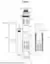
FIG. 1 is a forward-facing exploded view of the firearm suppressor tailored for a 22LR caliber, illustrating its internal components and their arrangement.
FIG. 2 is an exploded view of the rear portion of the firearm suppressor, allowing for the visibility of the inlet baffle module.
FIG. 3 is a forward-facing view of the southeast portion of the firearm suppressor.
FIG. 4 is a rear-facing view of the northwest portion of the firearm suppressor.
FIG. 5 is a cross-sectional view of the assembled suppressor, delineating the projected gas flow pathway within the device.
FIG. 6 is the section of the assembled suppressor in which the cutaway was performed, as illustrated in FIG. 5.
FIG. 7 is a left-oriented view that shows the visible components of the suppressor when fully assembled.
FIG. 8 is a right-oriented view that shows the visible components of the suppressor when fully assembled.
FIG. 9 is a rear-view that shows the visible components of the suppressor when fully assembled.
FIG. 10 is a forward view that shows the visible components of the suppressor when fully assembled.
FIG. 11 is a view of the fully assembled core of the suppressor that slides into the inner tube.
FIG. 12 is a view of the baffle module joints (18) and their alignment with nearby components blast deflection ring (9) and reverse gas flow chamber (12).
FIG. 13 is a view of the blast chamber spiral slots (20) located on the top portion of the component that are used to align and secure the blast chamber spacer (5).
FIG. 14 is a view of the core components assembled, with the nearby components that hold it in place and keep it aligned.
FIG. 15 is another view of the suppressor from a southwest camera angle.
FIG. 16 is an additional angle of the assembly from a northeast camera angle.
FIG. 17 is a large view of the inside portion of end cap (13), with the alignment notch visible and central aperture to allow the bullet to pass through.
FIG. 18 is a view of the outside portion of the end cap (13).
FIG. 19 is a view of the barrel (7) with line (23) representing the central aperture for the bullet to pass through.
FIG. 21 is a view of the barrel nut (6) as attached to the threads on the top of barrel (7).
FIG. 22 is a view of the flange (16) as assembled to inner tube (1).
FIG. 23 is a view of the northeast camera angle of flange (16) and inner tube (1).
FIG. 24 is a view of the outer tube (14) in an upright assembly along with an installed identification tag (15).
FIG. 25 is a view of the outer tube (14) in a top-down horizontal view.
FIG. 26 is a view of the outer tube (14) and identification tag (15) in an upright right-side view.
FIG. 27 is a view of the outer tube (14) and identification tag (15) in an upright forward view.
FIG. 28 is a view of the outer tube (14) and identification tag (15) in an upright side view with shaded components.
FIG. 29 is a view of the specific features of reverse gas flow chamber (12) from a top angle.
FIG. 30 is a view of the bottom portion of the reverse gas flow chamber (12).
FIG. 31 is a top view of the blast deflection ring (9).
FIG. 32 is a pivoted view of the blast deflection ring (9).
FIG. 33 is a bottom-facing view of the blast deflection ring (9).
FIG. 34 is a bottom-facing view of the blast chamber spiral (8).
FIG. 35 is a top-facing view of the blast chamber spiral (8).
FIG. 36 is a cutaway view of the blast chamber spiral (8).
FIG. 37 is a view of the point at which the cutaway in FIG. 36 was sliced.
FIG. 38 is a horizontal view of the blast chamber spacer (5).
FIG. 39 is a top view of the blast chamber spacer (5).
FIG. 40 is an upper pivoted view of the blast chamber spacer (5).
FIG. 41 is a bottom pivoted view of the blast chamber spacer (5).
FIG. 42 is a forward view of the arrangement and fitment of the blast chamber spacer (5) and blast chamber spiral (8).
FIG. 43 is a top pivoted view of the arrangement of extruded notches present on the blast chamber spacer (5) and how they align with the blast chamber spiral (8).
FIG. 44 is an outer view of the inlet baffle module (11), with the red lines illustrating the gas flow path through the baffles.
FIG. 45 is an outer view of the outlet baffle module (10), with the red lines illustrating the gas flow path through the baffles.
FIG. 46 is a view of the outlet baffle module (10) and the inlet baffle module, (11) aligned in their designed fitment in relation to the core components.
FIG. 47 is a view of the baffle assembly, specifically components outlet baffle module (10) and inlet baffle module (11), in their final assembly in relation to the core.
FIG. 48 is a side view of the male-threaded fastener (4). The top portion includes tool slots for a specialty wrench that will be included with the suppressor to loosen this component.
FIG. 49 is an upper view of the male-threaded fastener (4).
FIG. 50 is a bottom view of the male-threaded fastener (4) to gain a better vantage of the recessed notches to retain the barrel adapter (1) when the pinch plate nut (2) is fully tightened.
FIG. 51 is a view from another angle of the bottom portion of the male-threaded fastener (4), giving a side angle of the recessed notches that the top of the barrel adapter (1) contact.
FIG. 52 is a side angle view of the barrel adapter (1).
FIG. 53 is a view of the upper portion of the barrel adapter (1).
FIG. 54 is a view of the bottom portion of the barrel adapter (1).
FIG. 55 is a pivoted view from a bottom angle of the barrel adapter (1).
FIG. 56 is a side view of barrel adapter (1) and the male-threaded fastener (4) in an assembled state.
FIG. 57 is a top view of the barrel adapter (1) and male-threaded fastener (4).
FIG. 58 is a bottom view of the assembled barrel adapter (1) and male-threaded fastener (4).
FIG. 59 is a view of the bottom portion of the male-threaded fastener (4).
FIG. 60 shows a side view of the pinch plate nut (2).
FIG. 61 is a top pivoted view of the pinch plate nut (2).
FIG. 62 is a bottom view of the pinch plate nut (2).
FIG. 63 shows a pivoted bottom view of the pinch plate nut (2).
FIG. 64 is a side view of the barrel adapter (1) and pinch plate nut (2), assembled without the male-threaded fastener (4) in place.
FIG. 65 shows a pivoted top view of the barrel adapter (1) and pinch plate nut, (2) assembled without the male-threaded fastener (4) in place.
FIG. 66 shows a bottom view of the barrel adapter (1) and pinch plate nut (2), assembled without the male-threaded fastener (4) in place.
FIG. 67 is a pivoted bottom view of the barrel adapter (1) and pinch plate nut, (2) assembled without the male-threaded fastener (4) in place.
FIG. 68 is a side view of the identification tag (15).
FIG. 69 is a view of the rear portion of the identification tag (15), providing a better vantage point to view the thinner flange that extends past the front portion of the tag.
FIG. 70 is a top view of the serial identification tag (15), which depicts the radius of the tag.
FIG. 71 is a top pivoted view of the front portion of the serial identification tag (15).
FIG. 72 is an upper pivoted view of the outer tube (14) assembly and the serial identification tag (15).
FIG. 73 is a view of the assembled suppressor in a locked state, preventing any motion.
FIG. 74 is a view of the assembled suppressor in its first step towards rotational motion.
FIG. 75 is a view of the assembled suppressor, when pulled backwards towards the shooter to start rotation.
FIG. 76 is a view of the assembled suppressor after desired rotation of the vent has been achieved.
FIG. 77 is a view of the assembled suppressor, in a ready-to-lock and secure state after rotation has been achieved.
FIG. 78 is a view of the assembled suppressor in its new position, with the vent now located on the right side of the suppressor instead of the front.
FIG. 79 is a mockup view of the suppressor assembly when mounted to an M16 firearm.
FIG. 80 is a negative mold of the internal passages inside of the Blast Chamber Spiral (8) from a forward perspective.
FIG. 81 is a negative mold of the internal passages inside of the Blast Chamber Spiral (8) from a top-pivot perspective.
FIG. 82 is negative mold of the internal passages inside of the Blast Chamber Spiral (8) from a top perspective.
FIG. 83 is a negative mold of the internal passages inside of the Blast Chamber Spiral (8) from a bottom-pivot perspective.
FIG. 84 is a negative mold of the internal passages inside of the Blast Chamber Spiral (8) from a front view.
FIG. 85 is a negative mold of the internal passages inside of the Blast Chamber Spiral (8) from a front view with the cutaway performed.
FIG. 86 is a negative mold of the internal passages inside of the Blast Chamber Spiral (8) from a larger forward zoomed-in view.
DETAILED DESCRIPTION OF A PREFERRED EMBODIMENT
FIG. 1 presents an exploded view of the firearm suppressor tailored for a 22LR caliber, illustrating its internal components and their arrangement from a forward-facing camera perspective. The suppressor housing comprises an inner tube (1) and an outer tube (14), with the outer tube (14) incorporating an identification tag (15) that becomes a single unit after spot welding approximately 1-2 mm from the outside edge of the mount location of the tag on the outer tube. During assembly, the end cap (13) is welded in alignment with both the inner tube (1) and the outer tube (14), allowing the combined unit of the outer tube (14) and the identification tag (15) to slide into position over the inner tube (1). Subsequently, the flange (16) is either welded or threaded onto the inner tube (1). Assembly of the suppressor core involves using a central barrel (7) to align and secure the core components in a specific order onto the outer shaft of the barrel (7), later fastened with a barrel nut (6). The depicted order of core components includes a reverse gas flow chamber (12), outlet baffle module (10), inlet baffle module (11) shown in FIG. 2, blast deflection ring (9), and blast chamber spiral (8). Once assembled, the core is slid into the inner tube (1) and rotated to lock into place, aligning with the raised notch on the end cap (13). A blast chamber spacer (5) is then inserted and secured into the recessed notches on the upper portion of the blast chamber spiral (8). For mounting, the barrel adapter (1) is inserted into the inside hole of the male-threaded fastener (4), which is then screwed onto the flange (16) of the inner tube (1). Finally, the pinch plate nut (2) is installed onto the barrel adapter (1), completing the assembly process.
FIG. 2 shows an exploded view of the rear portion of the firearm suppressor, allowing for the visibility of inlet baffle module (11).
FIG. 3 shows an exploded view of the Southeast portion from a forward camera angle of the firearm suppressor.
FIG. 4 shows an exploded view of the Northwest portion from a rear camera angle of the firearm suppressor.
FIG. 5 illustrates a cross-sectional view of the assembled suppressor, delineating the projected gas flow pathway within the device. Upon firing a bullet, gases from the barrel enter the blast chamber, encountering heightened turbulence generated by the slotted holes encircling the blast chamber spacer (5). The bullet's obstruction at the central entrance of the barrel (7) redirects gases into the openings surrounding the face of the blast chamber spiral (8). Subsequently, the gas traverses through the blast chamber spiral (8), gradually decelerating before reaching the blast deflection ring (9). Here, gases enter through an opening on one side of the blast deflection ring (9), channeling them into the upper portion of the inlet baffle module (11). As the gas nears the tube's end, it encounters the reverse gas flow chamber (12), prompting a reversal in direction. The gas then proceeds into the outlet baffle module (10) before venting laterally through openings situated on the side of both the inner tube (1) and outer tube (14) that are in alignment with each other forming a single lateral vent (17). In other designs, this lateral vent (17) could have slotted openings, angled openings that direct gases at a somewhat forward angle such as 45 degrees forward or have a rotating cover that slides to change the size of the vent.
FIG. 6 illustrates the section of the assembled suppressor in which the cutaway was performed as illustrated in FIG. 5.
FIG. 7 shows the visible components of the suppressor when fully assembled from a left camera angle. Barrel adapter (1) is shown at the upper portion of the assembly. This is the component that attaches to the threaded portion at the end of a gun barrel. Pinch Plate Nut (2) is shown and can be loosened while attached to the gun barrel. To loosen, the shooter will rotate the Pinch Plate Nut (2) until the fully assembled forward end of the suppressor tube can be slid backwards and rotated. The rotation is blocked by pinch plate nut (2) when fully tightened by the ribs that are present at the base of barrel adapter (1) and the indentations on male-threaded fastener (4), allowing them to firmly seat together. Male-threaded fastener (4) can be seen installed into flange (16) with a threaded male portion on male-threaded fastener (4) and female thread portion on flange (16). Outer tube (14) can be seen with identification tag (15) installed. The identification tag (15) will have the manufacturer identifying information such as serial number, location, and company name. End cap (13) is shown at the bottom of the suppressor and will be welded permanently to the inner tube (1) components. Lateral vent (17) is shown here and will allow for the gases that travel through the entire length of the suppressor to escape. The location of lateral vent (17) on the side of the tubing may change based on the caliber or volume of gases in which the suppressor is designed to handle. The vent may move up or down and will be placed proportionally for the caliber it's designed for. The engravings that are visible on outer tube (14) are added for weight reduction of the outer tube (14), heat dissipation, and serve as a gripping point for the user to rotate or remove the assembly. These engravings are not required for overall functionality, and the outer tube (14) could be smooth, with no engravings or markings.
FIG. 8 shows the visible components of the suppressor when fully assembled from a right camera angle.
FIG. 9 shows the visible components of the suppressor when fully assembled from a rear camera angle.
FIG. 10 shows the visible components of the suppressor when fully assembled from a forward camera angle.
FIG. 11 shows the fully assembled core of the suppressor that slides into the inner tube (1). Reverse gas flow chamber (12) is installed first by sliding onto barrel (7) through a central hole, followed by inlet baffle module (11) and outlet baffle module (10). Notches are visible on the top of the reverse gas flow chamber (12) and allow for inlet baffle module (11) and outlet baffle module (10) to be joined together and secured. At the top of inlet baffle module (11) and outlet baffle module (10) there are extruded notches that slide into the outside edges of blast deflection ring (9). The blast chamber spiral (8) is then installed and rotated to align with a notch at the top of blast deflection ring (9) to maintain alignment. The assembly is then secured with barrel nut (6) in a functional alignment.
FIG. 12 illustrates the baffle module joints (18) and their alignment with nearby components blast deflection ring (9) and reverse gas flow chamber (12). Barrel (7) can be seen inserted through a central hole in gas loopback deflector (9). End cap joint (19) can be seen on the bottom of reverse gas flow chamber (12) and allows for alignment to end cap (13).
FIG. 13 shows the blast chamber spiral slots (20) located on the top portion of the component that are used to align and secure the blast chamber spacer (5).
FIG. 14 shows the core components assembled with the nearby components that hold it in place and keep it aligned. The notch on the side of end cap (13) aligns the core components, and the blast chamber spacer (5) is inserted into the recessed notches at the top of the blast chamber spiral (8).
FIG. 15 shows another view of the suppressor from a southwest camera angle. Line (21) shows the male-threaded fastener (4) bottom threads contacting the top portion of blast chamber spacer (5). The threads on the male-threaded fastener (4) extend at a minimum of 0.5-1 mm past the top of the blast chamber spacer (5) when the core is inserted into the inner tube (1). This allows for a secure fit of the core components and to prevent them from being loose inside of the tube. In the final production model, this excessive distance may be timed, or additional threads may be added or removed to allow the male-threaded fastener to fully seat and remain flush with the outer tube (14). Line (22) shows the alignment notch on end cap (13) and allows for the assembled core to be aligned in the proper orientation inside of the tube. The user will rotate the core until it slides into the notch and then secure the assembly by tightening male-threaded fastener (4) with an included specialty tool.
FIG. 16 shows an additional angle of the assembly from a northeast camera angle.
FIG. 17 shows a large view of the inside portion of end cap (13) with the alignment notch visible and central aperture to allow the bullet to pass through.
FIG. 18 shows the outside portion of end cap (13). This component will likely be machined with a CNC or Lathe and can be found in multiple material types including but not limited to, Inconel, 17-4 stainless steel, grade 5 Titanium or aluminum. To save on overall weight, grade 5 titanium may be selected. Additive manufacturing is also an option for manufacturing this component.
FIG. 19 shows barrel (7) with line (23) representing the central aperture for the bullet to pass through.
FIG. 20 shows barrel (7) with line (23) representing the central aperture for the bullet to pass through. The barrel (7) will be constructed using additive manufacturing methods with DMLS 3d-printing technology being the targeted method. Should CNC or Lathe manufacturing technology come out on top as the better choice of manufacturing, this technology would be used. Stronger materials will be used, such as Inconel, to ensure longevity of the barrel and its performance. In low pressure rounds, a different material may be selected for cost savings. The barrel (7) can be easily removed and replaced when worn beyond repair.
FIG. 21 shows the barrel nut (6) as attached to the threads on the top of barrel (7). The hexagonal barrel nut (6) will be constructed with Inconel to ensure improved strength and rigidity, as this will be one of the first components to meet gas from the barrel of the fired gun.
FIG. 22 shows the flange (16) as assembled to inner tube (1). Line (17) shows the gas vent location on inner tube (1) that upon assembly, will align with the expelling gas vent location on outer tube (14).
FIG. 23 shows a northeast camera angle of flange (16) and inner tube (1). The flange (16) will be constructed with traditional CNC or Lathe technology and the materials used can vary. The primary material up for consideration will be grade 5 titanium to add strength and save weight. Other versions that experience more internal pressure may use Inconel for added strength. Aluminum or 17-4 Stainless steel will be considered for versions that don't need weight savings or additional strength. Flange (16) may either be welded or threaded onto inner tube (1) to secure to the tube housing. On the inside of flange (16) the threads will mate with the male-threaded fastener (4), allowing the fastener to press against the top of the blast chamber spacer (5).
FIG. 24 shows the outer tube (14) in an upright assembly along with an installed identification tag (15).
FIG. 25 shows the outer tube (14) in a top-down horizontal view.
FIG. 26 shows the outer tube (14) and identification tag (15) in an upright right-side view. FIG. 27 shows the outer tube (14) and identification tag (15) in an upright forward view.
FIG. 28 shows the outer tube (14) and identification tag (15) in an upright side view with shaded components.
FIG. 29 highlights the specific features of reverse gas flow chamber (12) from a top angle. Line 25 shows the rounded bottom which allows for gas to move forward and then loop back 180 degrees around to the outlet baffle module (10). Line 26 shows the center opening, allowing the barrel (7) to pass through the center of the component. The barrel (7) will create an obstruction in the lower radius of the reverse gas flow chamber (12). But as you can see, the radius extends around the entire base, forming a bowl shape. Line 27 shows the custom fitted notches that allow for alignment of the inlet baffle module (11) and the outlet baffle module (10). The overall notch shapes aren't important. Any polygon shape or recess that prevents the movement of the upper connecting parts will work to align and restrict movement. The reverse gas flow chamber (12) may be either machined with a CNC or Lathe, or 3D-printed using additive manufacturing technology. The material type may vary based on the caliber selected. However, Grade 5 Titanium is planned. There are possibilities of using Inconel when strength is needed, or Aluminum or 17-4 Stainless when cost of manufacturing is an issue. The size of the radius in the picture shown is 15 mm in depth, but this depth could change based on the caliber selected, total volume of gases entering the suppressor tube, or overall mass of material present. The central hole may also change in size based on the size of the barrel (7) that is required.
FIG. 30 shows the bottom portion of the reverse gas flow chamber (12). Line 12 shows the recessed hexagonal opening that the barrel (7) slides into. The hexagonal shape can be changed to a square, rectangle, or any other polygon shape that prevents rotational movement of the barrel to lock into place. Line 29 shows the recessed opening that the notch located on end cap (13) slides into. In a different design, this could be a peg coming from the bottom of reverse gas flow chamber (12) that slides into the bottom face of end cap (13). The objective here is to align the bottom of the reverse gas flow chamber (12) so that the exit lateral vent (17) located on the side of outer tube (14) aligns perfectly with the gas flow pattern of the suppressor core. This notch is responsible for the alignment of the entire suppressor core components when they are fully assembled.
FIG. 31 shows a top view of the blast deflection ring (9). Line 30 shows the bulge in the center wall that is responsible for alignment with the blast chamber spiral (8) that connects above this component. Line 31 shows a bulge in the inside gas contact wall. This allows for extra wall thickness surrounding the notch on the bottom outside wall of the blast deflection ring (9) that the outlet baffle module (10) and inlet baffle module (11) slide into for alignment. On the left side of the image, you'll notice that there is a radius that extends approximately 5 mm up the inside side wall. Some of the gases that are exiting the blast chamber spiral (8) will make contact and pivot 90 degrees towards the opening on the right side. The gases will then travel down into the inlet baffle module (11). Any gases that come down through the side of the blast deflection ring (9) with the unrestricted opening will continue flowing straight through and into the inlet baffle module (11). The slope of the radius could be increased or decreased, speeding up the flow of gas or slowing it down. The slope of the radius could also change based on the caliber selected or the overall volume of gases the suppressor is rated to receive. The blast deflection ring (9) was designed to be additively manufactured with grade 5 Titanium. Inconel could be used as a substitute for increased strength where weight is not a factor. 17-4 Stainless Steel or Aluminum may be substituted for lower pressure gases should the need present itself. The component may also be machined with CNC and/or Lathe equipment, should the cost of manufacturing and capabilities of the equipment not be an issue.
FIG. 32 shows a pivoted view of the blast deflection ring (9). Line 32 highlights the notch at the base where the outlet baffle module (10) and inlet baffle module (11) meet and align. This notch is also responsible for pinching the baffles together and holding them in alignment around the outside of barrel (7). The notches could also be pegs, or holes with screws to maintain alignment and secure the components together. The pivoted view also gives you a better viewing point of the radius present on the left side that redirects the gases towards the right-side opening.
FIG. 33 shows the blast deflection ring (9) from a bottom facing view. This view gives you a better vantage point to notches and shows the alignment point at the base of the blast deflection ring (9). The location of the notches could change to any point in the outside of the radius if it secures and maintains the connecting baffle components.
FIG. 34 shows the blast chamber spiral (8) from a bottom facing view. Line 34 shows the openings present at the bottom. On this model, there are 6 openings. Each opening is a single and sealed coil that extends through the top of the spiral. They were designed this way to separate the gases firing into the spiral and slow them down before entering the blast deflection ring (9). This design could be improved by using specialized simulation software to create advanced acoustic structures, or simply acoustic metamaterials. By changing the angles of the coils and/or distance between the spirals you could essentially create vibrations in the core that could create destructive interference and cancel out certain frequencies that are present in the sound waves since the gases will be traveling through individual channels. Each coil can have its own resonant frequency, determined by factors such as its size, shape, and material properties. By tuning the dimensions and spacing of the coils, you can adjust their resonant frequencies to align with specific frequencies of the sound pressure you want to cancel. By positioning the coils in a specific pattern relative to the direction of the sound wave propagation, you can create regions where the waves from different coils interfere destructively. This means that the peaks and troughs of the waves align in such a way that they cancel each other out, resulting in reduced sound pressure at those locations. The number of openings or the size could also change based on the volume of gases received by the caliber fired. The blast chamber spiral (8) was designed to be additively manufactured with DMLS printing technology using Inconel materials for added strength and the high heat and pressure it will be subjected to. However, for lower pressure gases from smaller calibers and/or optimizing sound reduction, other materials may be used such as 17-4 Stainless Steel or Grade 5 Titanium.
FIG. 35 shows the blast chamber spiral (8) from a top facing view. Line 37 outlines the notches visible for alignment of the blast chamber spacer (5). These notches may not be required, should the notches on the inside edge of the blast chamber spacer (5) be removed. Line 38 shows the central opening that the barrel (7) slides through.
FIG. 36 shows a cutaway of the blast chamber spiral (8). Line 39 shows a sloped opening that outlines the path in which the gas from the gunshot will travel. Each of those pathways starts and ends with a single entrance, travel through a single pathway, then exit. They are stacked like a coil and each coil opening, length, width, and overall height is sketched and rotated on a central axis to create space in between, creating multiple internal spirals separated by internal walls. In other designs, the number of pathways or the connection in between could change based on certain improvements that may be discovered in the development phase. Line 40 represents an entrance opening for a single pathway. Line 41 represents an exit opening for the gas to continue traveling forward.
FIG. 37 shows the point at which the cutaway in FIG. 36 was sliced.
FIG. 38 shows the blast chamber spacer (5) in a horizontal view. Line 42 shows the notched inside portion of the spacer that allows for alignment with the blast chamber spiral (8). Line 43 shows the holes that run vertically through each of the notches that are designed to create more turbulence and slow down the entering gases into the blast chamber. Line 44 shows the arched angle at the top of the cutouts around the outside of the spacer. These arches were designed to accommodate overhang restrictions currently present with additive manufacturing. The cutouts may be removed entirely, along with the notches, should neither of those end up being needed. The cutouts were added initially to reduce the overall weight of the component. The component itself could simply be reduced to a round tube with a central opening if the only function is to create space in the initial blast chamber between the male-threaded fastener (4) and blast chamber spiral (8). The other function of this spacer is to also hold the core securely in place and prevent any looseness or vibration. This piece was designed to be 3D-printed using additive manufacturing technology with Inconel or grade 5 titanium materials. However, different materials may be used such as 17-4 Stainless Steel or Aluminum. CNC or Lathe manufacturing may also be used, should the design be simplified to a round tube.
FIG. 39 shows a top view of the blast chamber spacer (5). Line 45 shows the notches and their extent. In this 22LR model shown, the notches extrude 5 mm towards the center of the spacer.
FIG. 40 shows an upper pivoted view of the blast chamber spacer (5) to get a better look at the overall composition of the spacer and the arrangement of the extruded notches and the holes that run vertically up or down.
FIG. 41 shows a bottom pivoted view of the blast chamber spacer (5). Line 46 shows the extruded notches that are visible from the base of the spacer.
FIG. 42 shows the arrangement and fitment of the blast chamber spacer (5) and the blast chamber spiral (8) from a forward view.
FIG. 43 shows a top pivoted view of the arrangement of extruded notches present on the blast chamber spacer (5) and how they align with the blast chamber spiral (8).
FIG. 44 depicts the outer view of the inlet baffle module (11), with the red lines illustrating the gas flow path through the baffles. The gas first enters through the upper opening, having passed through the blast deflection ring (9). The angled baffles facilitate forward movement while inducing a reverse direction to gradually decelerate the gases. As the pathway narrows in the entrance to the next baffle set, the gases continue to decelerate until they exit and are redirected by the reverse gas flow chamber
(12) into the outlet baffle module (10). In the context of the inlet baffle module system, while the angles of the baffles play a role in facilitating the forward movement of gas, their specific angles may not be as critical as ensuring the continuous forward flow of the gas. The primary objective is to maintain a consistent flow trajectory that allows the gas to traverse through the system efficiently. If the design enables the gas to move forward and gradually decelerate, the exact angles of the baffles may have some flexibility without significantly impacting the overall functionality of the system. Therefore, the emphasis lies more on the continuity of the gas flow rather than the precise angles of the baffles. However, this design could be modified by adding smaller slotted holes on the inside faces of the component. This could reduce heat buildup and weight, while still achieving similar results. This change could apply to both the outlet baffle module (10) and inlet baffle module (11). This component was designed to be manufactured with additive manufacturing technology, specifically DMLS. The materials chosen for this will be lightweight when weight is a concern, specifically grade 5 titanium. When strength is a concern, Inconel will be used. 17-4 stainless steel and Aluminum may be used for lower pressure calibers, where heat and high pressure aren't an issue.
FIG. 45 depicts the outer view of the outlet baffle module (10), with the red lines illustrating the gas flow path through the baffles. The gas enters through the bottom opening, having passed through the blast deflection ring (9), rerouting the gas in a 180-degree fashion, and heading towards the exit lateral vent (17). Line 49 shows the entrance baffles, that are angled upwards and funnel the gas into the next set of baffles, where it will continue to flow up through the baffle stack. When the gas contacts the center baffle, it's redirected either around the center baffle or is deflected into the outside area, contacting the baffles on the left or right. Continuing forward, it deflects on additional baffles, until it eventually makes its way to the exit lateral vent (17), where the gas laterally vents out of the side perpendicular to the shooter. The primary objective is to maintain a consistent flow trajectory that allows the gas to traverse through the system efficiently. If the design enables the gas to move forward and gradually decelerate, the exact angles of the baffles may have some flexibility without significantly impacting the overall functionality of the system. Therefore, the emphasis lies more on the continuity of the gas flow rather than the precise angles of the baffles. Line 50 highlights the alignment notch that is present on both outlet baffle module (10) and inlet baffle module (11). This feature ensures alignment in the core and allows both baffles to be secured to the core itself. This component was designed to be manufactured with additive manufacturing technology, specifically DMLS. The materials chosen for this will be lightweight when weight is a concern, specifically grade 5 titanium. When strength is a concern, Inconel will be used. 17-4 stainless steel and Aluminum may be used for lower pressure calibers, where heat and high pressure aren't an issue.
FIG. 46 shows the outlet baffle module (10) and the inlet baffle module (11) aligned in their designed fitment in relation to the core components. While these two components could be manufactured as one solid piece, the two components were halved to eliminate the need for unnecessary support structures due to overhang limitations with additive manufacturing technologies. Aggressive overhangs exceeding 45 degrees typically require support structures with current 3D printing technologies. The extra support structures require additional work and employee overhead that is required to be removed. By halving them, you eliminate the need for a large majority of these support structures, decreasing production time and post-processing steps. Line 51 shows the alignment tabs at the top of the assembled baffles. One corner of these tabs has a radius to ensure that the component is assembled in the core in the correct orientation.
FIG. 47 shows another angle of the baffle assembly, specifically components outlet baffle module (10) and inlet baffle module (11) in their final assembly in relation to the core. Line 52 shows the bottom alignment recesses. These hold the baffles securely in place and in alignment when the core components are assembled and prevent them from spreading apart. The current shape is a rectangular pattern for this feature. The top lip of the reverse gas low chamber (12) also molds to the overall shape of the baffles to add extra support in addition to this rectangle. However, any polygon shape or peg that prevents separation or further movement or separation of the two components will also work.
FIG. 48 shows a side view of male-threaded fastener (4). The top portion includes tool slots for a specialty wrench that will be included with the suppressor to loosen this component. Line 53 shows the rectangular slots that are patterned around the outside radius of the top portion. This design was chosen because of the nearest connecting part, the pinch plate nut (2). The pinch plate nut (2) is hexagonal shaped and will be loosened or tightened frequently during normal use of the suppressor. Requiring separate tools for this decreases the chances of the user accidentally loosening the male-threaded fastener (4) and causing the internal components to become loose in the process. This component will be manufactured with traditional CNC and/or Lathe technology. Additive manufacturing will be substituted if cost analysis proves to be an effective measure. However, 3D printers currently struggle with producing precise threads. So additional overhead would need to be considered if that route is chosen. The type of material will largely depend on the caliber rating, but 17-4 stainless steel or grade 5 titanium will be chosen, depending on the caliber rating. Aluminum and Inconel may be substituted, depending on the aforementioned factors.
FIG. 49 shows an upper view of the male-threaded fastener (4). Line 54 shows the central aperture of the component, allowing for the barrel adapter (1) to slide through.
FIG. 50 shows a bottom view of the male-threaded fastener (4) to gain a better vantage of the recessed notches to retain the barrel adapter (1) when the pinch plate nut (2) is fully tightened. This prevents any lateral movement and stops the suppressor housing from rotating.
FIG. 51 shows another angle from the bottom portion of the male-threaded fastener (4), giving a side angle of the recessed notches that the top of the barrel adapter (1) contact.
FIG. 52 shows a side angle of the barrel adapter (1). Line 57 shows the male threads that are present on the outside to accommodate the pinch plate nut (2). Line 58 shows the hexagonal nut that serves as a wrench flat to allow for easy removal and tightening to the end of a threaded gun barrel. Line 56 shows the extruded ribs on the upper face on the bottom pinch plate that hold the suppressor in alignment when the pinch plate nut (2) is tightened. The ribs are approximately 2 mm in height and the male threads are 5 mm in height. This allows you to loosen the pinch plate nut (2) without removing it entirely to allow for the complete forward assembly to rotate without removing the nut. These dimensions will change based on the caliber the suppressor is designed for and the overall length and diameter of the suppressor. More taller and rigid ribs may be required for larger suppressors. This design could be improved by utilizing a centrally located tube with an extruded lip on one side, and welded on the other side, joining two separate component tubes together with a spring-loaded button, switch, or a flip-up tab that secures and prevents rotation. If this improvement was made, you could potentially eliminate the need for the pinch plate nut (2) and barrel adapter (1), and male-threaded fastener (4), decreasing to a singular component that would be similar to a hub compatible quick-disconnect mount, except allowing for rotation. This component was designed to be manufactured using traditional CNC or Lathe technology, with the materials being grade 5 titanium, stainless steel, Inconel, or aluminum depending on the final caliber rating.
FIG. 53 shows the upper portion of the barrel adapter (1). Line 59 highlights the center female threads that screw onto the male threaded portion of a firearm barrel. The threads extend through the entire overall height and rely on the shoulder present on the firearm barrel to stop rotation when tight. If no shoulder is present, a different adapter could be manufactured with a built-in shoulder to stop rotation when contact is made to the inside shoulder. The design is modeled in ½″×28 threads, suitable for most threaded 22LR caliber barrels. However, this piece was designed to easily be replaced, should different adapters for varying thread types be needed.
FIG. 54 shows the bottom portion of the barrel adapter (1). Line 60 shows the central opening allowing for the bullet to travel through the suppressor.
FIG. 55 shows a pivoted view from a bottom angle of the barrel adapter (1). This view allows you to see the internal female threads and their seamless extent through the bottom of the component.
FIG. 56 shows the barrel adapter (1) and the male-threaded fastener (4) in an assembled state from a side view. Line 61 shows the outer male threads that allow for the pinch plate nut (2) to be secured. Line 62 shows the male threaded portion of male-threaded fastener (4) that attaches to flange (16) that is attached to inner tube (1).
FIG. 57 shows a top view of barrel adapter (1) and male-threaded fastener (4). Line 63 illustrates the gap present between the two components, that allows the threaded portion of barrel adapter (1) to pass through. The assembly is then secured by pinch plate nut (2) to prevent unwanted rotation or misalignment of the tube components.
FIG. 58 shows a bottom view of the assembled barrel adapter (1) and male-threaded fastener (4). Line 64 shows the gap between the outer edge of the barrel mount adapter and its location inside of male-threaded fastener (4). This alignment allows for free movement when rotating the assembled tube components. The bottom plate can push forward into the suppressor tube and movement forward will not be restricted by any internal components as the overall diameter of this piece is slightly less than the internal diameter of the inner tube (1).
FIG. 59 shows the bottom portion of the male-threaded fastener (4). Line 65 shows the extended lip with a large wall thickness. This extra thickness allows the lip to protrude further inside of the inner diameter of inner tube (1), securing and putting downward pressure on the blast chamber spacer (5) preventing any unwanted movement of the core components.
FIG. 60 shows a side view of pinch plate nut (2). Line 66 shows a flat portion of the hexagonal shape, serving as a wrench flat to tighten or loosen the nut from the assembly. Line 69 shows a chamfered portion of the nut. This is purely aesthetic and not required. This component was designed to be manufactured with traditional CNC or Lathe technology. The materials used will be relative to the materials used in the outer tube components. Grade 5 titanium, Inconel, Aluminum, and 17-4 stainless steel are all considered, depending on the caliber rating of the suppressor.
FIG. 61 shows a top pivoted view of the pinch plate nut (2). Line 67 shows the female threaded portion of the nut, with the threads traveling top to bottom to allow for full rotation of the nut on the assembly.
FIG. 62 shows a bottom view of the pinch plate nut (2). Line 68 highlights the central aperture, allowing for the nut to be attached to the outside male threaded portion of the barrel adapter (1).
FIG. 63 shows a pivoted bottom view of the pinch plate nut (2). Line 70 shows the flat portion that will allow the nut to tighten and align flush to the top portion of male-threaded fastener (4).
FIG. 64 shows a side view of the barrel adapter (1) and pinch plate nut (2) in an assembly without the male-threaded fastener (4) in place.
FIG. 65 shows a pivoted top view of the barrel adapter (1) and pinch plate nut (2) in an assembly without the male-threaded fastener (4) in place.
FIG. 66 shows a bottom view of the barrel adapter (1) and pinch plate nut (2) in an assembly without the male-threaded fastener (4) in place.
FIG. 67 shows a pivoted bottom view of the barrel adapter (1) and pinch plate nut (2) in an assembly without the male-threaded fastener (4) in place.
FIG. 68 shows a side view of the identification tag (15). Line 71 shows the flange that is present along the outside of this component. This allows for the identification tag (15) to be slid into the rear of the outer tube (14) to prevent it from falling forward and held into place during assembly. The inside of the outer tube (14) has a recess for the outer flange of the identification tag (15) that allows for the snug fitment of the identification tag (15). The flange located on the outer edges of the identification tag (15) in this example is half the height of largest thickness of the tag. In this example of a 22LR tag, the tag portion is 1 mm thick and the flange is 0.5 mm thick. However, the thickness may change based on the caliber rating for the suppressor. Line 73 shows the forward-facing portion of the identification tag (15). This is the portion that will include any registering marks required and not limited to any names, logos, serial numbers, or other identifying information related to the manufacturer of the assembled suppressor. The outer tube (14) and identification tag (15) will be spot welded together permanently in spots located 1-2 mm past the outer edge of the front portion of the tag in either the top, bottom, left, or right depending on what is necessary to hold into place securely. The locations of the spot welds will either be identified with witness marks or small recessed holes on the outside of the outer tube (14) or using manual measurements post manufacturing of the outer tube (14) component. This will join the two components into a singular component. Suppressors sometimes will experience baffle strikes from a bullet or incur other damage to the outer assembly or internal components that render them unusable. Having a separate identification badge lowers this risk and eliminates the need for costly or labor-intensive replacements of components and allows for the manufacture to reduce the time needed to replace critical parts and remain compliant with the current ATF regulations. The manufacturer will be able to drill out the spot welds and remove the identification plate from the outer tube assembly, so long as the tag is not damaged, to easily replace it if necessary. This was designed to be manufactured with CNC and/or lathe technology, using stainless steel, aluminum, grade 5 titanium or Inconel, depending on the caliber rating of the suppressor.
FIG. 69 shows the rear portion of the identification tag (15), providing a better vantage point to view the thinner flange that extends past the front portion of the tag.
FIG. 70 shows a top view of the serial identification tag (15) and allows you to view the radius of the tag. The radius matches that of the outer tube (14) component.
FIG. 71 shows a top pivoted view of the front portion of the serial identification tag (15).
FIG. 72 shows an upper pivoted view of the outer tube (14) assembly and the serial identification tag (15). Line 73 shows the location of the serial identification tag (15) when assembled into the outer tube (14). Line 74 shows the location of the lateral vent (17).
FIG. 73-78 illustrates an animation of the rotation of the entire assembly by the user when changing the location of the lateral vent (17).
FIG. 73 shows the assembled suppressor in a locked state, preventing any motion.
FIG. 74 shows the assembled suppressor in its first step towards rotational motion. The user will need to loosen the pinch plate nut (2) to prepare for rotation.
FIG. 75 shows the assembled suppressor when pulled backwards towards the shooter to start rotation. The user will need to loosen the pinch plate nut (2) and grab the forward assembly and pull backwards towards the loosened pinch plate nut (2) to release the ribs present on the barrel adapter (1).
FIG. 76 shows the assembled suppressor after desired rotation of the vent has been achieved.
FIG. 77 shows the assembled suppressor in a ready-to-lock and secure state after rotation has been achieved. The pinch plate nut (2) will need to be re-tightened to fully lock back in place and prevent any misalignment or further rotation of the assembly.
FIG. 78 shows the assembled suppressor in its new position with the vent now located on the right side of the suppressor instead of the front. This changes the direction entirely so that the gases will vent outside of the suppressor. This benefits the shooter and allows for controlled venting of any gases to provide any additional safety or concealment that may be required.
FIG. 79 shows a mockup of the suppressor assembly when mounted to an M16 firearm. The vent location is placed towards the right side of the shooter in this scenario.
FIG. 80 shows a negative mold of the internal passages inside of the Blast Chamber Spiral (8) from a forward perspective. This view allows you to see the paths in which the gases flow through the spiral. Line 75 shows the entrance points where the gas will flow in from the initial blast chamber. In this model, there are 6 independent passages where the gas will split once entering and continue forward movement. Each individual coil when stretched out is 143 mm in length. In relation, the overall height of the blast chamber spiral component in its completed assembly is 22 mm. The number of passages, the length and the angle of the coils can change depending on the caliber the blast chamber spiral is designed for.
FIG. 81 shows a negative mold of the internal passages inside of the Blast Chamber Spiral (8) from a top-pivot perspective.
FIG. 82 shows a negative mold of the internal passages inside of the Blast Chamber Spiral (8) from a top perspective.
FIG. 83 shows a negative mold of the internal passages inside of the Blast Chamber Spiral (8) from a bottom-pivot perspective. Line 76 shows the exit points where the gas will flow out of the blast chamber spiral (8).
FIG. 84 shows a negative mold of the internal passages inside of the Blast Chamber Spiral (8) from a front view. Line A shows the plane in which the cutaway for FIG. 85 was performed.
FIG. 85 shows a negative mold of the internal passages inside of the Blast Chamber Spiral (8) from a front view with the cutaway performed. This allows you to see the angles and space or wall thickness between the flow passages.
FIG. 86 shows a negative mold of the internal passages inside of the Blast Chamber Spiral (8) from a larger forward zoomed-in view.
Claims
I claim:1. A firearm suppressor comprising:
a tubular body having a rear end with an barrel attachment facility and a forward end defining a bullet exit aperture;
a rear portion of the body defining an expansion chamber;
an interior tube concentric with the body and having a rear tube end spaced apart from the attachment facility;
a gas transmission facility forward of the expansion chamber and defining a plurality of helical passages encircling a rear portion of the tube;
the helical passages each having a rear opening communicating with the expansion chamber, and a forward end communicating with an intermediate interior portion of the body;
a gas transmission element forward of the intermediate portion and surrounding the tube, and having an articulated passage with an entrance communicating with the intermediate portion of the body, and extending forward proximate the forward end of the body, and having an exit aperture in a lateral aperture of the body proximate the intermediate portion.
Images & Drawings included:


Sources:
- United States Patent and Trademark Office - verify current appl. status at the USPTO↗
Recent applications in this class:
- » 20260118085 2026-04-30
SUPPRESSOR HEAT SHIELD - » 20260104220 2026-04-16
FIREARM SUPPRESSOR WITH GAS RECIRCULATION AND MODULAR COMPONENTS - » 20260098698 2026-04-09
SOUND SUPPRESSOR FOR A FIREARM - » 20260098697 2026-04-09
GUN SUPPRESSOR WITH GAS SPLITTING - » 20260098696 2026-04-09
FIREARM SUPPRESSION DEVICE - » 20260071840 2026-03-12
SONIC SIGNATURE SUPPRESSOR FOR FIREARMS AND FIREARM EQUIPPED WITH SUCH - » 20260063384 2026-03-05
FIREARM SUPPRESSOR ASSEMBLY, AND APPARATUS AND METHOD FOR AUDIBLE SIGNATURE REDUCTION OF A FIREARM - » 20260055985 2026-02-26
Suppressor - » 20260055984 2026-02-26
SUPPRESSOR WITH GAS CROSS FLOW AND REDUCED BACK PRESSURE - » 20260049785 2026-02-19
FIREARM SUPPRESSOR WITH PROGRESSIVE ROTATION BAFFLE ARRANGEMENT