EYE PROTECTION DEVICE
US20260123697A1
2026-05-07
19/380,167
2025-11-05
Smart Summary: An eye protection device includes a visor that covers the eyes. It has a clear film that rolls out from one spool and wraps around the visor before being collected by another spool. A guide helps the film move smoothly over the visor. There is also a mechanism to keep the film in place on the visor. This design helps protect the eyes while maintaining visibility. 🚀 TL;DR
Abstract:
The present invention relates to an eye protection device comprising: a visor and a transparent material that is a film of transparent material mounted and deployed from a first spool and received by a second spool so that a layer of film is arranged over an outer face of the visor; a guide for guiding the transparent material over the visor from the first spool to the second spool; and a securement mechanism to secure at least part of the transparent material to the visor.
Applicant:
Interested in similar patents?
Get notified when new applications in this technology area are published.
Classification:
A41D13/1184 » CPC main
Professional, industrial or sporting protective garments, e.g. surgeons' gowns or garments protecting against blows or punches protecting only a particular body part; Protective face masks, e.g. for surgical use, or for use in foul atmospheres with protection for the eyes, e.g. using shield or visor
A41D13/1161 » CPC further
Professional, industrial or sporting protective garments, e.g. surgeons' gowns or garments protecting against blows or punches protecting only a particular body part; Protective face masks, e.g. for surgical use, or for use in foul atmospheres Means for fastening to the user's head
A41D13/11 IPC
Professional, industrial or sporting protective garments, e.g. surgeons' gowns or garments protecting against blows or punches protecting only a particular body part Protective face masks, e.g. for surgical use, or for use in foul atmospheres
Description
FIELD OF THE INVENTION
The present invention relates to an eye protection device, in particular a device for protecting vision through a visor.
BACKGROUND
In many societies across the world there is increasingly a need for safe and effective industrial processes.
In industrial cleaning, medical, and scientific fields, workers are exposed to hazardous substances, which can compromise their safety as current protective face visors often become dirty or fogged, reducing visibility and effectiveness.
Additionally, the process of cleaning or replacing these visors can be cumbersome and time-consuming.
Splashes of liquid or debris may soil a visor and block or smear vision, so a user has to stop their activity, such as jet washing and clean the visor to continue. This is very time consuming and unsafe as the user's eyes may be exposed whilst the visor is cleaned.
The present invention overcomes these problems.
PRIOR ART
GB2601665 (YOUNG) discloses a mud shield for a goggle, the mud shield comprising: a shield body configured to be disposed over at least a portion of a goggle.
WO2008037493 (KNIGHT et al) discloses a visor assembly comprising a lens and a transparent strip overlying one face of the lens and displaceable longitudinally across the lens, wherein the strip is located in a guideway mounted to the said one face of the lens, the guideway having opposite longitudinal guide rails between which the strip is received and which laterally retain the strip during displacement across the lens, and wherein the assembly further includes a cover releasably mounted to the guideway to retain the strip in the guideway, the guideway and cover being arranged to allow viewing through the lens.
U.S. Pat. No. 4,748,697 HODNETT face mask with interchangeable lenses, comprising a substantially flexible cowl shaped to substantially cover at least the eyes of a user; an open window provided in said cowl; a pair of spaced, curved, substantially rigid tracks removably carried by said cowl, said tracks spanning said window in spaced relationship for slidably receiving said lenses in end-to-end relationship and positioning said lenses sequentially in said window; and canister means carried by one end of said tracks for enclosing said lenses in rolled configuration and dispensing said lenses in said window responsive to manual and sequential extension of said lenses along said tracks.
SUMMARY OF THE INVENTION
According to a first aspect of the present invention there is provided an eye protection device comprising: a visor and a transparent material deployed from a first spool and received by a second spool so that when the transparent material is deployed a layer of the transparent material is arranged over an outer face of the visor; at least one guide guides the transparent material over the outer face of the visor from the first spool to the second spool; and a securement mechanism is operative to temporarily secure at least part of the transparent material to the outer face of the visor.
In this way a transparent material is arranged over the visor to provide a protective outer layer and a clean layer can be arranged over the visor at any time by unwinding the transparent material from the first spool onto the second spool. This allows soiled transparent material to be removed from the viewing region and wound on to the second spool and a clean part of the transparent material replaces the soiled transparent material so that the viewing region remains clear.
Advantageously the wearer does not therefore need to remove the visor to clean it and therefore safety is enhanced as the wearer's eyes remain protected at all times.
It is appreciated that there are multiple uses for a visor where it may become soiled and require cleaning, such as when jet washing, driving some vehicles, cycling, working in a laboratory, operating machinery, or tools such as when welding, cutting, or when working in humid conditions, or transition from hot to cold environments which may cause a visor to accumulate condensation.
For example, a wearer may protect their eyes with a visor when jet washing. When spray or debris builds on the visor it may need to be removed for cleaning because the wearer cannot see properly through the visor, but with the present invention the transparent material over the visor can simply be replaced with minimal effort by a wearer.
The securement mechanism acts to secure the transparent material against the visor to form a seal so that particles or moisture cannot enter between the transparent material and the visor, in particular the viewing region of the visor. In this way the viewing region of visor is always protected from being soiled or scratched.
The securement mechanism may be around parts of the edges of the transparent material, such as in segments along the edges, or along the long edges of the transparent material or may be a continuous loop around the viewing region.
In a preferred embodiment the eye protection device is arranged on a frame with head attachment means so that the device can be easily donned and doffed. The head attachment means may include one or more strap to assist with securing the device to a wearer.
It is appreciated that the device may be fitted to frame. In this way the device may be retrofitted to any headpiece that includes a visor. For example the device may include attachment means for connection to a frame.
The transparent material is a length of film. Long edges of the length of film are arranged in the guide which provides a groove so that the transparent material is guided over the outer face of the visor.
The visor and replaceable transparent material (transparent film) are formed from materials with low-friction properties, so that the transparent material can glide over the visor with easy and will not scratch or tarnish the visor.
Preferably the transparent material and/or the visor have anti-scratch and/or anti-fog properties to allow smooth sliding without abrasion or optical haze. For example the transparent material and visor may have anti-scratch/anti-fog finish or coating.
In a preferred embodiment the visor is formed from optically clear PET (polyethylene terephthalate) or polycarbonate with a hard-coat (abrasion-resistant) layer and hydrophilic anti-fog coating.
In a preferred embodiment the transparent film is formed from Thermoplastic Polyurethan Film (TPU films) which may also have comparable coatings as the visor.
The finish or coatings on the visor and/or film (transparent material) may act to reduce friction, resist scuffing, prevent fogging or condensation, and may provide anti-static properties to minimize dust attraction.
In a preferred embodiment the transparent film is formed from recycled and/or recyclable material.
In a preferred embodiment the guide is arranged on an outer face of the visor so that the transparent material is guided relative to the visor. The guide may be formed by a length of material that is adhered to the outer face of the visor and creates or defines a lip or groove that extends from visor to define the groove along which an edge of the transparent material is received and travels.
In a preferred embodiment a guide is provided for each long edge of the transparent material (film) so that the upper edge and lower edge of the length of transparent film are guided across the outer face of the visor.
In some embodiments part of the guide may be provided on the frame supporting the visor.
The securement mechanism acts to place the transparent material in contact with the visor so that it is not possible for moisture or debris to collect between the transparent material and the visor, therefore protecting the viewing region. Keeping the transparent material in contact with the visor also ensures optimal visibility.
In a preferred embodiment the securement mechanism is adjustable. For example so that the securement mechanism is not in constant contact with the transparent material and pressing it against the visor, allowing for the transparent material to be released from the visor when a new section of transparent material is deployed.
Preferably part of the securement mechanism that engages against the transparent material and visor is flexible so as to be able to match the shape of the visor and to be able to deform to assist with creating a seal.
In some embodiments the securement mechanism is a resiliently deformable layer that may be pressed against the transparent material in use to hold the transparent material (film) in place tightly against the visor or released from the transparent material and thereby the visor when replacement transparent material is passed across the visor. For example, the resiliently deformable layer may be formed from a cellular structure such as foam or neoprene or may be formed from rubber or silicone. The resiliently deformable layer is pressed against the transparent material and thereby the visor to create a seal between the visor and the transparent material. For example, a user may press the resiliently deformable layer against the transparent material to create a seal or there may be a mechanical means to move the resiliently deformable layer against the transparent material and to release the resiliently deformable layer from the transparent material. This may be a simple clamp type configuration.
The resiliently deformable layer may be around part of the viewing area or may surround the viewing area.
In a preferred embodiment the securement mechanism is an inflatable gasket inflated by an inflation device. The inflation device is connected to the gasket. Typically there is at least one valve to retain selected status of the gasket (inflated/deflated). In this way the gasket is inflated to engage with the transparent material, pressing it against the visor, and is deflated to release the transparent material from the visor.
In a preferred embodiment the gasket is provided on the visor and is a continuous loop that surrounds the viewing region. In this way all edges of the viewing region are forced against the transparent material and thereby the visor. The gasket is inflated to engage with the transparent material that passes over the visor, so that the gasket is forced against the transparent material and the transparent material is thereby forced against the visor to the create a seal. Advantageously the pressure applied by the inflated gasket on the transparent material against the visor creates a seal without requirement for tensioning of the transparent material.
In some embodiments there may be more than one gasket, each gasket covering a different part of the edge of the viewing region. For example one gasket running along a lower edge of the transparent material, and a second gasket running along an upper edge of the transparent material.
The gasket is ideally fixed in an open channel that is fixed to the visor. When inflated the gasket extends from the channel towards the opening which allows the gasket to come in contact with the transparent material and press the transparent material against the visor that is parallel to the transparent material and prevent movement of the transparent material over the visor as well as creating a seal.
When the gasket is deflated the gasket retracts against the channel to which it is fixed, thereby disconnecting the gasket from the transparent material, breaking the seal, and allowing the transparent material to move with respect to the visor.
In preferred embodiments the open channel is part of the guide. In this way the inflatable gasket is at least adjacent to long edges of the transparent material or may surround the viewing region when there is a continuous loop gasket. This allows the gasket to easily able to close a space between the edge of the transparent material, or edge of the viewing region, and the visor when it is inflated.
An inflation device is provided to inflate and deflate the gasket. Preferably the gasket is inflated with air, but it is appreciated that in some embodiments a liquid may be used.
The inflation device may be a manual inflation means such as a manual pump, or an automatic inflation means such as a motorized pump.
Preferably a button, lever or bulb is provided on the eye protection device to activate and deactivate inflation. For example manual inflation may be achieved by pushing and release a bulb of the manually operable inflation pump.
In an alternative embodiment a motorized pump may be activated by pressing a button to inflate and/or deflate the gasket.
Typically the inflation device includes at least one valve to control release of air from the gasket.
The gasket is configured to withstand high-pressure splashback and to prevent ingress of moisture or debris behind the transparent material. In this way the viewing region of the visor over which the transparent material lies, remains protected.
In a preferred embodiment the gasket is inflated to a range between 12 to 15 PSI so that the gasket forms a tight seal against the visor and transparent material when inflated.
The transparent material is arranged on the first spool and is unwound from the first spool whilst being wound onto the second spool. In this way there is a length of transparent material across the outer face of the visor.
The transparent material is held under tension between the first and second spools so that the transparent material provides a taut transparent layer with no folds or kinks that may affect vision.
The tension may be achieved by an arrangement of rods and/or rollers. These may be associated with the spools. For example the transparent material may be associated with nip rollers, such as crowned rollers to tension the transparent material.
Additionally the visor is preferably curved so that the transparent material is pulled across a curved surface maintaining constant contact and meaning that the transparent material and visor are curved to match the curvature of a wearer's face.
The transparent material is also held under tension to avoid creation of air bubbles between the transparent material and the visor.
In some embodiments a resiliently deformable fin may be provided to assist with pressing the transparent material against the visor. The resiliently deformable fin may be provided where the transparent material is deployed from the spool and first contacts the visor, and/or along the guide at the gasket edge and/or where the transparent material is last in contact with the visor before being wound onto the second spool so that the transparent material is encouraged against the visor across the viewing region. For example the fin may be a squeegee fin to expel air during film movement.
The fin or plurality of fins may be arranged on the visor, or the frame, or the guide, or the spool.
Advantageously the use of a fin located at or near to where the transparent material is deployed from the first spool ensures that pressure may be applied across the width of the transparent material so that its whole width is placed in contact against the visor as it is deployed, removing any air between the transparent material and the visor.
In some embodiments the guide may include at least one vent to release air from between the transparent material and the visor that may be forced out by the fin(s).
In some embodiments the device may include a vacuum plenum to extract air from between the transparent material and the visor.
In some preferred embodiments the device has a motor to drive at least one of the spools. In this way the displacement of the transparent material over the visor is driven by the motor. This allows the transparent material to be quickly replaced with a new section of transparent material if it becomes damaged or soiled. Preferably only the second spool that receives the used transparent material (film) is motorized to pull new transparent material from the first spool over the visor and onto the second spool.
In some embodiments activation of the motor to rotate the spool may be automated so that the turning is activated when a change of transparent material section is required. The motor is activated in response to a signal that indicates that the transparent material has been soiled and requires changing.
The signal may be generated by means of at least one sensor detecting moisture and/or particles on the visor, or a sensor detecting a movement or voice command. For example, receipt of a sensor signal may trigger the motor for a preset duration which is sufficient for a new section of transparent material to be deployed.
In an embodiment of the device with an automated spool, it is appreciated that the securement mechanism, such as the inflation device, may also be automated so that the soiled transparent material can be released from the visor and reconnected to the replacement transparent material. For example the motorized pump may be automated. The activation signal may be generated by means of at least one sensor detecting a parameter (moisture/debris/sound/movement) to activate the motors (motor for a spool/motor for an inflation pump) in the required sequence to allow the gasket to be deflated to release the transparent material before the new transparent material can be deployed by means of rotation of the spool. The pump motor is then activated again this time to inflate the gasket to recreate the seal. In this way inflation and deflation means is automated as well as movement of the transparent material across the visor by means of the motorized spool.
A preferred automated system of operation includes receipt of a signal to initiate changing of the transparent material; deflating the gasket to release the transparent material, initiating the second spool to rotate so as to deploy a clean transparent material section from the first spool and to receive the soiled transparent material section to the second spool, to reinflate the gasket by activating the inflation device to create a seal between the transparent material and the visor.
In some embodiments deflation of the gasket constitutes the triggering event for activation of the motor that drives the spool to enable deployment of new transparent material and recovery of used/soiled transparent material. In this way detection of one event may activate a next event or cease a previous event.
In some embodiments the sequence of events that cause a new transparent material section to be deployed may be controlled by a timer, so that each event occurs at a designated time.
An automated sequence of the spool and inflation device ensures correct operation without reliance on a user action, thereby eliminating operator error and ensuring functional integrity of the visor.
It is appreciated that a device including automated operation includes a controller operatively connected to a processor which issues command signals to the spool motor and to the motorized pump in response to a signal detected by at least one sensor that indicates that a new section of transparent material is required.
In a preferred embodiment each spool receives a cartridge that holds the transparent material and can be added to or removed from the spool. The cartridge may be a tube/reel which transparent material wrapped around. In this way the cartridge and thereby the transparent material can be easily replaced when the length of film on the cartridge has been used. For example a cartridge can be easily removed and replaced.
The film (transparent material) may have an indicator of its approaching end so as to ensure the user is prewarned to change cartridge. For example the transparent material may have a visual indicator, so as a line which becomes visible towards the end of the reel of transparent material.
A spool is arranged on either side of the visor so that the transparent material is deployed across the viewing region of the visor. For example the transparent material may pass from left to right over the viewing region of the visor. In this way the first spool contains clean unused transparent material and the second spool holds soiled, damaged, used transparent material.
In some embodiments the transparent material on the first spool is enclosed by a casing so the clean transparent material on the first spool cannot become soiled, for example from surrounding spray, such as from a pressure washer.
In another embodiment the transparent material is enclosed by the cartridge that is received to the spool. For example the spool may be a rod that receives a cartridge with an enclosed reel of transparent material. The transparent material is dispensed from the cartridge when the second spool rotates to pull the transparent material across the visor. The spool collecting the used transparent material does not require a reel as the transparent material may wind directly onto the second spool.
In some embodiments of the device there is a blade which wipes the film as it is received on to the second spool. For example, the second spool may be arranged within a casing and there may be a slot through which the sullied transparent material is received and a blade the wipes the transparent material as it passes through the slot or before it reaches the slot. The blade is preferably resiliently deformable.
The blade, or plurality of blades may be arranged on the spool, or on the frame or on the visor. The blade acts to remove any substance on the transparent material to prevent accumulation on the spool or within the casing.
In some embodiments of the device the visor extends above and/or below the viewing region over which the transparent material passes. This is because the transparent material is provided to ensure good visibility at all times, whereas an upper or lower part of the visor may provide protection to the face but vision through this region is not required.
In preferred embodiments the device has a frame for fitting the device to a wearer's head with the visor arranged at least over a wearer's eyes to provide protection. In some embodiments the device the frame includes head attachment strap, such as chin strap to secure the device to the wearer and prevent it become dislodged when donned and thereby ensuring a wearer's eyes remain protected.
In some embodiments of the device the head attachment strap is elastomeric for additional comfort and fit for the wearer.
Preferably the head attachment strap has a length adjustment means so that the device can be securely fitted to different wearers.
A preferred embodiment of the invention will now be described by way of example only and with reference to the Figures in which:
BRIEF DESCRIPTION OF FIGURES
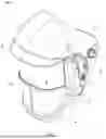
FIG. 1 shows an isometric view of a first embodiment of the eye protection device;
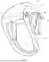
FIG. 2 shows a second isometric view of the embodiment of the device shown in FIG. 1;
FIG. 3 shows a reverse isometric view of the embodiment of the device shown in FIG. 1;
FIG. 4 shows an exploded isometric view of the embodiment of the device shown in FIG. 1;
FIG. 5 shows a second exploded isometric view of the embodiment of the device shown in FIG. 1;
FIG. 6 shows a reverse exploded isometric view of the embodiment of the device shown in FIG. 1;
FIG. 7 shows a second reverse isometric view of the embodiment of the device shown in FIG. 1;
FIG. 8 shows a second embodiment of the eye protection device with a gasket that is a complete loop and a guide that includes channel for the gasket;
FIG. 9 shows a cross section of a guide arranged on a visor with a groove for the transparent material and a channel for the inflatable gasket showing a transparent material pressed against the visor by a gasket;
FIG. 10A shows a guide with an open channel on a visor (with no gasket);
FIG. 10B shows the guide and the open channel with a deflated gasket; and
FIG. 10C shows examples of the guide with an open channel with an inflated gasket.
DETAILED DESCRIPTION OF FIGURES
With reference to the figures there are two embodiments of the invention 99, 100.
FIGS. 1 to 7 show a first embodiment 99.
FIG. 8 shows a second embodiment 100.
Like parts have like references.
The eye protection devices 99, 100 comprise: a visor 3; and the transparent material 2A which passes over a viewing region 2.
The eye protection device 99, 100 is fitted to a wearer by means of a frame 1 that has a head attachment means 13.
The transparent material 2A is a film of transparent material that is fed from a first spool 75A to a second spool 75B and provides a layer over a viewing region 2 on the visor 3.
The transparent material is not shown as a connected length of material in FIGS. 1 to 8, but in FIG. 8 the location of the viewing region over which the transparent material is positioned is indicated by reference 2 and in FIGS. 9, 10A, 10B and 10C the position of the transparent material 2A is shown.
The two spools 75A, 75B are mounted on the frame 1 within casings 7, 17.
Casing 7 is on the left side of the device 99, 100, casing 17 is on the right side of the device 99,100.
Casing 7 includes a housing 77 for the spool 75A. Inflation bulb 5 is arranged to extend from part of the housing 77. The inflation bulb 5 is fed by an air tube 79 and has a valve 6. The air tube 79 is a hollow tube delivering air pressure to inflate the gasket 61 for a tight seal of the transparent material against the visor 3.
The valve 6 is a bleed valve to allow exhaust of air from the gasket 61 when it is deflated. The valve 6 releases air from the inflated gasket, allowing the user to change and advance the transparent material 2A.
A door 76 provides access to the spool 75A. A spool release button 12 enables removal or an empty reel from the spool 75A. A release mechanism (not shown) holds the reel (cartridge) to the spool and the release button 12 frees this mechanism. The release mechanism may be a releasable interlock between part of a reel and the spool 75A.
Casing 17 includes a housing 77 for the spool 75B. A motor 72 drives the spool 75B. A motor button 73 is operatively connected to the PCB on part 74. A hinged door 76 provides access to the spool 75B for removal of used transparent material 2A on the spool 75B that is holding soiled transparent material 2A. The transparent material 2A may collect directly on the second spool 75B or may collected on a displaceable reel on the second spool 75B so that the reel can be removed from the spool 75B to remove the used transparent material 2A.
The pictured embodiments 99, 100 have a manually operable motorised spool 75B that has a motor 72 which drives rotation of the spool 75B on which transparent material 2A is received so that clean transparent material 2A on the first spool 75A is deployed and pulled towards the second spool 75B. Use/soiled transparent material 2A is recovered onto the second spool 75B.
Replacing the transparent material 2A section over the viewing region 2 on the visor 3 enables users to effortlessly clear their field of view when the visor is soiled, for example splashed with water/particles/chemicals simply by pressing a button 73 which initiates the motor 72 which drives rotation of the second spool 75B.
The spools 75A, 75B are rotating parts contained in plastic housings 77 which are mounted on the frame 1 and visor 3 so that the spools 75A, 75B are to either side of the visor 3. The plastic housing 77 is accessed by means of a door 76 so that spools 75 or reels or cartridge upon the spools (not shown) can be added and removed, dispensed, and received.
Spool 75B has a geared motor 72 that drives the spool 75B to advance clean transparent material 2A across the visor. The motor 72 is activated by a switch (not shown) that is part of a motor actuation button 73 on the right side of the device 99, 100.
This is large, easy-to-press button 74 for actuating motor 72, enables quick transparent material 2A (transparent film) advancement across the visor 3.
The housing door 76 is hinged providing access to the spool 75, ensuring easy replacement and maintenance of film.
A battery (on part 74) is provided to power the motor 72. This is preferably a Li-Po battery and is associated with a printed circuit board (PCB) (part of 74, see rear view in FIG. 6).
The visor 3 is arranged on a front face of the frame 1 so that the visor is worn in use over the wearer's face.
In the pictured embodiments 99, 100 the frame 1 is arranged around the wearer's face having two sides 1B, 1C, an upper head cover 1D and chin protection 8. The sides 1B, 1C are connected by the head attachment means 13 which comprises an inelastic strap 13 that is a loop, controlled by adjustment dials 4. The adjustment dial 4 also acts a pivot point to allow the wearer to fold the visor up when not in use.
The strap 13 that is arranged inside the frame 1 and contacts the wearer's forehead may be padded (not shown).
The visor 3 is preferably an impact resistant polycarbonate visor 3 which protects the wearer's face, for example from both splash back of liquid such as water or chemicals, and also from items such as mud or shrapnel which may fly towards the wearer's face when in use.
To ensure a watertight seal between the visor 3 and the transparent material 2A (transparent film) the device 99, 100 has an inflatable gasket 61. The inflatable gasket 61 is preferably formed from silicone.
The inflatable gasket 61 is controlled (inflated/deflated) by a manual inflation bulb 5, that allows the wearer to inflate and deflate the gasket 61 to force the transparent material 2A against the visor 3 so that the visor is protected by the transparent material and moisture or items/debris cannot collect therebetween which may cause restricted vision such as smearing across the visor.
In both embodiments 99, 100 the gasket 61 is a continuous loop arranged on the outer face of the visor 3.
In the pictured embodiments at least part of the gasket 61 is arranged within a channel that is part of a guide 10.
In FIGS. 1 to 7 a guide 10 extends around a lower part of the gasket 61 providing a protected channel for the gasket 61 and guiding the transparent material 2A.
In FIG. 8 the guide 10 is a continuous rectangle that includes an open channel for all of the gasket 61.
The gasket 61 surrounds a section of the visor 3 in front of the user's eyes to define a viewing region 2 over which the transparent material 2A passes.
The guide 10 in both embodiments 99, 100 is the guide for edges of the transparent material 2A (see FIG. 9) and also provides the channel for the gasket 61.
The guide 10 ensures the transparent material remains close to the visor 3 as it is deployed/received by the spools 75.
In FIGS. 1 to 7 the frame 1 includes a rigid peak 9 that has a second guide 9A that also acts to guide the transparent material 2A and contain the gasket 61.
FIG. 8 shows a second embodiment 100 of the eye protection device. In this embodiment the guide 10 has a channel (see FIG. 9) in which the gasket 61 is seated which corresponds to the shape of the gasket and is continuous. The guide 10 is rectangular and is adhered to an outer face of the visor 3.
In FIG. 9 there is an example of a cross section of the visor 3 with a guide 10 that is adhered to the visor 3. The guide has two slots, a channel 11A for the inflatable gasket, and a groove 11B for the transparent material.
Channel 11A contains the gasket 61 which is inflated and deflated as required. Groove 11B is the guide which guides the length of transparent material 2 across the visor 3. The groove 11B is defined by the visor 3 and the guide 10.
The channel 11A is a shaped region of the guide 10 in which the gasket 61 is fixed. The channel 11A is curved to correspond to the tubular gasket 61.
In FIG. 9 the gasket 61 is a tube that is shown in an inflated state so that the gasket 61 presses against the transparent material 2A forcing it against the visor and thereby preventing anything getting between the A 2A and visor 3 within the viewing area.
FIGS. 10A, 10B and 10C show a second embodiment of the guide 10. The guide 10 is angular formed from three sides 10A, 10B, 10C arranged at 90 degrees to each other to define a rectangular channel cross section in which the gasket 61 is arranged and along which the transparent material edge is received. Side 10C is shorter to define an opening 10D.
In FIG. 10A no gasket is shown.
The gasket 61 is fixed to side 10B of the guide 10 and when the tubular gasket 61 inflates it fills the channel defined by the guide 10 and bulges through the opening 10D forcing the gasket 61 against the transparent material 2A onto the visor 3.
The invention has been described by way of examples only and it will be appreciated that variation may be made to the above-mentioned embodiments without departing from the scope of protection as defined by the claims.
Claims
1. An eye protection device comprising: a visor and a transparent material deployed from a first spool and received by a second spool so that when the transparent material is deployed a layer of the transparent material is arranged over an outer face of the visor; at least one guide guides the transparent material over the outer face of the visor from the first spool to the second spool; and a securement mechanism is operative to temporarily secure at least part of the transparent material to the outer face of the visor.
2. An eye protection device according to claim 1 wherein the eye protection device is supported by a frame which includes a head attachment means.
3. An eye protection device according to claim 2 wherein the first and second spools are mounted on the frame and/or the visor.
4. An eye protection device according to claim 1 wherein the securement mechanism is adjustable.
5. An eye protection device according to claim 4 wherein the securement mechanism includes a resiliently deformable layer.
6. An eye protection device according to claim 4 wherein the securement mechanism comprises an inflatable gasket that is inflated by an inflation device, whereby when inflated the gasket urges the transparent material to contact the outer face of the visor.
7. An eye protection device according to claim 6 wherein the inflation device is a manually operable pump.
8. An eye protection device according to claim 6 wherein the inflation device includes a motorised pump.
9. An eye protection device according to claim 6 wherein the inflatable gasket is arranged in an open channel.
10. An eye protection device according to claim 1 includes at least one motor which drives at least one of the spools.
11. An eye protection device according to claim 1 wherein the first spool receives a displaceable cartridge that includes the transparent material wrapped thereon.
12. An eye protection device according to claim 1 wherein the first and second spools are arranged on lateral sides of the visor either side of a wearer's viewing region.
13. An eye protection device according to claim 1 including a blade to wipe an outer face of the transparent material prior to winding it onto the second spool.
14. An eye protection device according to claim 1 including at least one fin to assist with pressing the transparent material against the outer face of the visor.
15. An eye protection device according to claim 1 including at least one vent to release air from between the transparent material and the outer face of the visor.
16. An eye protection device according to claim 1 including a vacuum device, such as a plenum, for extracting air from a space between the transparent material and the outer face of the visor.
17. An eye protection device according to claim 1 wherein the at least one guide has a groove for receiving and guiding a long edge of the transparent material.
18. An eye protection device according to claim 6 wherein the at least one guide has a groove for receiving and guiding a long edge of the transparent material, and the guide includes the groove for the transparent material and a channel for the inflatable gasket.
19. An eye protection device according to claim 1 wherein the inflation device includes a motorized pump and includes at least one motor which drives at least one of the spools, the eye protection device further including a controller operatively connected to a processor which issues a command signal to the spool motor and to the motorised pump in response to a signal detected by at least one sensor that indicates that a new section of transparent material is required.
20. A method of using the eye protection device according to claim 1 having an automated system of operation including the steps of: receiving a signal to initiate changing a region of the transparent material; deflating the gasket to release the transparent material; initiating the second spool to rotate so as to deploy a clean region of the transparent material from the first spool; receiving a soiled region of the transparent material on the second spool; and reinflating the gasket by activating the motorised pump to create a seal between the transparent material and the visor.
Images & Drawings included:


Sources:
- United States Patent and Trademark Office - verify current appl. status at the USPTO↗
Similar patent applications:
- » 20230255299
EYE PROTECTION, EYE PROTECTION DEVICE FOR A HEADGEAR AND HEADGEAR COMPRISING AN EYE PROTECTION DEVICE - » 20190204439
Three-dimensional reconstruction system and method, mobile device, eye protection method, AR device - » 10139837
Eye-protection device having dual high voltage switching - » 11820059
Microprocessor based automatically dimmable eye protection device with interruption prevention - » 10398878
Eye protection device - » 18913327
Maskless respiratory and eye protection device for aerosols and vapors including chemical, biological, radiological, and nuclear (CBRN) contaminants - » 20050057544
Eye-protection device having dual high voltage switching - » 19194120
Maskless respiratory and eye protection device for aerosols and vapors including chemical, biological, radiological, and nuclear (CBRN) contaminants - » 20050122440
Eye-protection device having dual high voltage switching - » 10741622
Microprocessor based automatically dimmable eye protection device with interruption prevention
Recent applications in this class:
- » 20260107994 2026-04-23
HEAT-RESISTANT PROTECTIVE SHIELD - » 20260053215 2026-02-26
Eyewear - » 20260053214 2026-02-26
FACE MASK AND SHIELD COMBINATION - » 20260026561 2026-01-29
ZIP STRAP TETHER - » 20260020628 2026-01-22
LOW HAZE UV BLOCKING REMOVABLE LENS STACK - » 20260020627 2026-01-22
WRAPAROUND EYE SHIELD SYSTEMS AND METHODS - » 20250351900 2025-11-20
FILM LAMINATE, METHOD FOR MANUFACTURING FILM LAMINATE, PROTECTIVE EQUIPMENT, AND METHOD FOR MANUFACTURING PROTECTIVE EQUIPMENT - » 20250325053 2025-10-23
EYE PROTECTION APPARATUS - » 20250261709 2025-08-21
FACE SHIELD WITH ADJUSTABLE TENSIONING - » 20250169557 2025-05-29
PERSONAL PROTECTION SYSTEM AND METHOD