AIR MATTRESS ASSEMBLY AND METHOD THEREFOR
US20260123765A1
2026-05-07
18/940,059
2024-11-07
Smart Summary: An air mattress comes with an inflatable pillow that can be placed inside it. This pillow can be inflated to support a pregnant person’s belly while lying on their stomach. The mattress also has a cooling gel layer to keep the user cool and a memory foam layer for extra comfort. It is designed to help users feel supported and comfortable in different resting positions. Overall, it aims to provide a better sleeping experience, especially for pregnant or postpartum individuals. 🚀 TL;DR
Abstract:
An air mattress assembly includes an air mattress and an inflatable pillow insert that may be removably positioned in a cavity in the air mattress. The inflatable pillow insert may be selectively inflated to accommodate an abdominal region of a user while resting in a prone position during various stages of pregnancy and/or postpartum. In one embodiment, the air mattress assembly includes a cooling gel layer that may provide cooling benefit to a user. In another embodiment, the air mattress assembly includes a memory foam layer that may provide additional cushioning benefit to a user. In all embodiments, the air mattress assembly may provide support and comfort to a user while resting in a prone position. A user may also rest in other positions on the assembly, as may be desired.
Assignee:
- Star W Professional Services LLC 1 🇺🇸 Gilbert, AZ, United States
Applicant:
Interested in similar patents?
Get notified when new applications in this technology area are published.
Classification:
A47C27/083 » CPC main
Spring, stuffed or fluid mattresses or cushions specially adapted for chairs, beds or sofas; Fluid mattresses or cushions of pneumatic type with pressure control, e.g. with pressure sensors
A47C27/088 » CPC further
Spring, stuffed or fluid mattresses or cushions specially adapted for chairs, beds or sofas; Fluid mattresses or cushions incorporating elastic bodies, e.g. foam
A47G9/1027 » CPC further
Bed-covers; Counterpanes; Travelling rugs; Sleeping rugs; Sleeping bags; Pillows; Pillows Details of inflatable pillows
A47C27/08 IPC
Spring, stuffed or fluid mattresses or cushions specially adapted for chairs, beds or sofas Fluid mattresses or cushions
A47G9/10 IPC
Bed-covers; Counterpanes; Travelling rugs; Sleeping rugs; Sleeping bags; Pillows Pillows
Description
TECHNICAL FIELD
The present application relates generally to air mattresses and methods therefor and, more particularly, to an air mattress assembly that supports a pregnant user while in a prone position, and methods therefor.
BACKGROUND
During pregnancy, a woman's body undergoes many changes that can be uncomfortable. For instance, during pregnancy, it is often difficult for a woman to find a comfortable sleeping position. This is particularly true as the pregnancy progresses and a woman's abdominal region expands. Physicians generally recommend that a pregnant woman sleep on her side—preferably on her left side—because this position places the least amount of pressure on the inferior vena cava and also promotes increased blood flow among internal organs and the developing fetus. If a woman is not comfortable in this position, sleeping on her right side is recommended as an alternative. Conversely, it is not recommended for the woman to sleep on her back, particularly during the later stages of pregnancy, because studies have shown that doing so can lead to various problems, including backaches, breathing problems, digestive issues, hemorrhoids, low blood pressure, and decreased blood circulation. Further, sleeping on her stomach may be discouraged because doing so can be practically uncomfortable on the woman's expanded abdominal region and, as well, can lead to neck and shoulder problems, and can generally cause soreness, stiffness, and pain. This guidance can be disappointing and also frustrating for pregnant women who naturally are stomach sleepers, or who would prefer to sleep on their stomachs at times, but find they cannot do so comfortably during pregnancy.
A solution to the aforementioned problems was disclosed in U.S. Pat. No. 5,679,040 issued to Bianchi-Holm. The apparatus disclosed in U.S. Pat. No. 5,679,040 may be utilized to support a pregnant user while in a prone position. However, the apparatus disclosed in Bianchi-Holm has some limitations. For example, while the apparatus includes a central portion that can be inflated to accommodate an abdominal region of a pregnant user, said central portion is an integral part of the overall apparatus and is not removable. As a result, in the event that irreparable damage occurs to any portion of the apparatus, the entire apparatus will require replacement, which can be expensive. Furthermore, the apparatus disclosed in U.S. Pat. No. 5,679,040 provides an air mattress body having an overall substantially tubular design, which some users may find undesirable and/or uncomfortable, particularly for use long term as a sleeping apparatus.
Another common issue facing women during pregnancy is a general feeling of being overheated. This is typically a result of natural hormonal changes that occur during pregnancy, as well as increased blood supply to the skin. When feeling overheated, pregnant women may have a general sense of feeling warmer, have night sweats, and experience overall discomfort.
A need therefore exists for an air mattress assembly that enhances a user's overall comfort while in a prone position during pregnancy, that can accommodate changing dimensions of the user's abdominal region during various stages of pregnancy and postpartum, that comprises multiple components that may be replaced if necessary without requiring replacement of the entire assembly, and that can provide a cooling benefit for the user.
The present disclosure addresses the aforementioned problems as well as provides other, related advantages.
SUMMARY
In accordance with one embodiment of the present invention, an air mattress assembly is disclosed. The air mattress assembly comprises, in combination: an air mattress comprising a top surface, a bottom surface, and at least one sidewall surface, the top surface having a cavity formed therein; and an inflatable pillow insert configured to be removably positioned in the cavity, the inflatable pillow insert configured to be adjustably inflated.
In accordance with another embodiment of the present invention, an air mattress assembly is disclosed. The air mattress assembly comprises, in combination: an air mattress comprising a top surface, a bottom surface, and a plurality of sidewall surfaces, the top surface having a cavity formed therein; a channel formed in the air mattress, the channel juxtaposed between the top surface and the bottom surface; an inflatable pillow insert comprising: a top surface, a bottom surface, a sidewall, and a stem coupled to the sidewall, wherein the stem is configured to be positioned in the channel of the air mattress; wherein the inflatable pillow insert is configured to be removably positioned in the cavity, the inflatable pillow insert configured to be adjustably inflated; and a cooling gel layer comprising: a top surface, a bottom surface, an interior region defined by the top surface and the bottom surface, the interior region configured to contain a cooling gel, and an opening, wherein the opening is configured to correspond to outer dimensions of the inflatable pillow insert; wherein the bottom surface of the cooling gel layer is configured to contact the top surface of the air mattress.
In accordance with another embodiment of the present invention, an air mattress assembly is disclosed. The air mattress assembly comprises, in combination: an air mattress comprising a top surface, a bottom surface, and a plurality of sidewall surfaces, the top surface having a cavity formed therein; a channel formed in the air mattress, the channel juxtaposed between the top surface and the bottom surface; an inflatable pillow insert comprising: a top surface, a bottom surface, a sidewall, and a stem coupled to the sidewall, wherein the stem is configured to be positioned in the channel of the air mattress; wherein the inflatable pillow insert is configured to be removably positioned in the cavity, the inflatable pillow insert configured to be adjustably inflated; and a memory foam layer comprising: a top surface, a bottom surface, and an opening, wherein the opening is configured to correspond to outer dimensions of the inflatable pillow insert; wherein the bottom surface of the memory foam layer is configured to contact the top surface of the air mattress.
BRIEF DESCRIPTION OF THE DRAWINGS
The present application is further detailed with respect to the following drawings. These figures are not intended to limit the scope of the present application, but rather, illustrate certain attributes thereof. In the descriptions that follow, like parts are marked throughout the specification and drawings with the same numerals, respectively. The drawing figures are not necessarily drawn to scale and certain figures can be shown in exaggerated or generalized form in the interest of clarity and conciseness. The disclosure itself, however, as well as a preferred mode of use and further objectives and advantages thereof, can be best understood by reference to the following detailed description of illustrative embodiments when read in conjunction with the accompanying drawings, wherein:
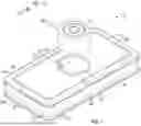
FIG. 1 is an exploded, perspective view of an exemplary air mattress assembly, in accordance with one aspect of the present disclosure;
FIG. 2 is a side view of the air mattress assembly of FIG. 1;
FIG. 3 is a top view of the air mattress assembly of FIG. 1;
FIG. 4 is another side view of the air mattress assembly of FIG. 1;
FIG. 5 is a bottom view of the air mattress assembly of FIG. 1;
FIG. 6 is another side view of the air mattress assembly of FIG. 1;
FIG. 7 is a cross-sectional view of the air mattress assembly of FIG. 1, taken through line A-A of FIG. 5;
FIG. 8 is a side view of an exemplary air mattress, in accordance with one aspect of the present disclosure;
FIG. 9 is a top view of the air mattress of FIG. 8;
FIG. 10 is another side view of the air mattress of FIG. 8;
FIG. 11 is a bottom view of the air mattress of FIG. 8;
FIG. 12 is another side view of the air mattress of FIG. 8;
FIG. 13 is a cross-sectional view of the air mattress of FIG. 8, taken through line B-B of FIG. 11;
FIG. 14 is a perspective view of an exemplary inflatable pillow insert, in accordance with one aspect of the present disclosure;
FIG. 15 is a top view of the inflatable pillow insert of FIG. 14;
FIG. 16 is a side view of the inflatable pillow insert of FIG. 14;
FIG. 17 is another side view of the inflatable pillow insert of FIG. 14;
FIG. 18 is a cross-sectional view of the inflatable pillow insert of FIG. 14, taken through line C-C of FIG. 17;
FIG. 19 is a bottom view of the inflatable pillow insert of FIG. 14;
FIG. 20 is a top view of an exemplary air valve, in accordance with one aspect of the present disclosure;
FIG. 21 is a side view of the air valve of FIG. 20;
FIG. 22 is a top perspective view of the air valve of FIG. 20;
FIG. 23 is a bottom perspective view of the air valve of FIG. 20;
FIG. 24 is another side view of the air valve of FIG. 20;
FIG. 25 is an exploded, perspective view of an exemplary air mattress assembly, in accordance with one aspect of the present disclosure; and
FIG. 26 is an exploded, perspective view of an exemplary air mattress assembly, in accordance with one aspect of the present disclosure.
DESCRIPTION OF THE APPLICATION
The description set forth below in connection with the appended drawings is intended as a description of presently preferred embodiments of the disclosure and is not intended to represent the only forms in which the present disclosure can be constructed and/or utilized. The description sets forth the functions and the sequence of steps for constructing and operating the disclosure in connection with the illustrated embodiments. It is to be understood, however, that the same or equivalent functions and sequences may be accomplished by different embodiments that are also intended to be encompassed within the spirit and scope of this disclosure.
Embodiments of the exemplary air mattress assembly employ an air mattress and inflatable pillow insert designed to support a user during pregnancy. In this way, the present invention can be utilized by a pregnant user desiring to rest while in a prone position. Furthermore, the present invention can be utilized by a user postpartum while the user's abdominal region remains in an expanded form. Still further, the present invention can be utilized by a user during other times regardless of the form of the user's abdominal region, as may be desired.
In its simplest form, the exemplary air mattress assembly generally comprises an air mattress and an inflatable pillow insert. The air mattress includes an opening configured to receive the inflatable pillow insert therein. The inflatable pillow insert can be adjustably inflated to various degrees of expansion. This can accommodate various sizes of an abdominal region of a pregnant user as such region expands during various stages of pregnancy, thereby allowing the user to comfortably rest while in a prone position. Various embodiments of the exemplary air mattress assembly may further comprise the additional feature of a cooling gel layer positioned on a top surface of the air mattress to provide a cooling benefit to the user. Various embodiments of the exemplary air mattress assembly may further comprise the additional feature of a memory foam layer positioned on a top surface of the air mattress to provide additional cushioning benefit to the user.
FIGS. 1-26, together, disclose various embodiments of an air mattress assembly 10 (hereinafter “assembly 10”) and related components of the present invention. Referring first to FIG. 1, an embodiment of the assembly 10 comprises the following principal components: an air mattress 12 and an inflatable pillow insert 14 configured to be removably positioned in the air mattress 12. The air mattress 12 and inflatable pillow insert 14 of the assembly 10 may be fabricated from a thermoplastic polyurethane material (“TPU”) or some such other material suitable for inflatable apparatus applications, as may be desired.
Referring still to FIG. 1, the air mattress 12 will be discussed in further detail. As seen in this embodiment, the overall configuration of the air mattress 12 is substantially rectangular. However, it should be generally understood that the air mattress 12 may take on various other shapes, as may be desired. The air mattress 12 includes a top surface 16 configured to accommodate a user thereon and a bottom surface 22. The air mattress 12 includes at least one sidewall surface. As seen in this embodiment, the air mattress 12 includes a pair of horizontally spaced apart sidewalls 18, each positioned along a length of the air mattress 12 and juxtaposed between the top surface 16 and bottom surface 22. Thus, sidewalls 18 are positioned lengthwise along the air mattress 12. The air mattress 12 further includes a pair of horizontally spaced apart sidewalls 20, each positioned along a width of the air mattress 12 and juxtaposed between the top surface 16 and bottom surface 22. Thus, sidewalls 20 are positioned widthwise along the air mattress 12. As seen in this embodiment, the air mattress 12 further includes corner portions 24. A total of four corner portions 24 are provided, with a single corner portion 24 positioned along one of each of four corners of the air mattress 12, such that each corner portion 24 is juxtaposed between a sidewall 18 and a sidewall 20. The corner portions 24 may take on an overall curved configuration, as shown in this embodiment. Alternatively, the corner portions 24 may take on another suitable configuration, as may be desired.
Referring still to FIG. 1, a circular cavity 26, defined by a circumferential wall 28 and a floor 29, is positioned in the air mattress 12. As can be seen in this embodiment, the cavity 26 is preferably centrally positioned in the air mattress 12. In this way, the inflatable pillow insert 14, when positioned in the cavity 26, can correspond to the abdominal region of a user when said user is in a prone position on the air mattress 12. An interior diameter of the cavity 26 is configured to correspond to outer dimensions of the inflatable pillow insert 14, such that the cavity 26 of the air mattress 12 is adapted to receive the inflatable pillow insert 14 therein. An elongated channel 30, in communication with the circumferential wall 28, is configured to receive a stem 52 of the inflatable pillow insert 14 therethrough, as further discussed herein.
The air mattress 12 may further include a plurality of exterior ridges 38 formed along outer perimeters of the top surface 16 and bottom surface 22. As seen in this embodiment, the ridges 38 may protrude outwardly from the top 16 and bottom 22 surfaces of the air mattress 12. The exterior ridges 38 may strengthen and provide reinforcement to exterior portions of the air mattress 12 and, in this way, may help to protect exterior portions of the air mattress 12 from damage, such as punctures and the like. The air mattress may further include interior ridges 40 formed along inner regions of the top surface 16 and bottom surface 22 of the air mattress 12 (as seen in FIGS. 3, 5, and 11).
The air mattress 12 further includes an interior chamber region 36 (as may be seen in FIGS. 7 and 13), defined by interior surfaces of the top surface 16, sidewalls 18, sidewalls 20, bottom surface 22, and circumferential wall 28, and in which air may be contained when the air mattress 12 is inflated.
Referring now to FIG. 8, the air mattress 12 further includes an opening 32 which may be formed along one of the sidewalls 18. An interior diameter of the opening 32 is configured to correspond to outer dimensions of an air valve 34 (as seen in FIGS. 1 and 21-24) of the assembly 10, such that the opening 32 of the air mattress 12 is adapted to receive the air valve 34 therein, as further discussed herein. As seen in this embodiment, the opening 32 is positioned adjacent to an exterior opening 42 of the channel 30. However, it should be generally understood that the opening 32 could be positioned in other locations of the air mattress 12, as may be desired.
Regarding dimensions of the air mattress 12, in one embodiment, the air mattress 12 can have an overall length of approximately 75 inches, an overall width of approximately 38 inches, and an overall thickness of approximately 12 inches. Further, in one embodiment, the cavity 26 may have a diameter of approximately 18 inches and a depth of less than approximately 12 inches. Further, in one embodiment, the channel 30 may have an interior diameter of approximately 1.75 inches and a length of approximately 9.5 inches. However, it should be generally understood that the dimensions of the air mattress 12 may deviate from these measurements, as may be desired.
Referring now to FIGS. 1 and 14-19, the inflatable pillow insert 14 will be discussed in further detail. As seen in this embodiment, the overall configuration of the inflatable pillow insert 14 is substantially cylindrical. However, it should be generally understood that the inflatable pillow insert 14 may take on other shapes, as may be desired, as long as a shape of the inflatable pillow insert 14 corresponds to a shape of the cavity 26 of the air mattress 12. The inflatable pillow insert 14 includes a top surface 44 configured to accommodate an abdominal region of a user of the air mattress assembly 10 and a bottom surface 48. The inflatable pillow insert 14 further includes a circumferential sidewall 46 juxtaposed between the top surface 44 and bottom surface 48. As seen in this embodiment, a stem 52 is coupled to the circumferential sidewall 46 at a base 54 of the stem 52 and protrudes outwardly from the circumferential sidewall 46. As seen in this embodiment, the base 54 may be generally sloped in the direction of a body 56 of the stem 52, in order to correspond to a slope of a mouth 31 (as seen in FIGS. 1 and 26) of the channel 30 formed along the circumferential sidewall 28 of the air mattress 12. In this way, the stem 52 may be snugly fitted into place when the stem 52 is positioned in the channel 30 of the air mattress 12 (as seen in FIG. 7). The stem 52 is formed of a hollow, elongated tubular member and includes an opening 58 at a distal end of the stem 52. An interior diameter of the opening 58 is configured to correspond to outer dimensions of an air valve 34 (as seen in FIG. 1) of the assembly 10, such that the opening 58 of the stem 52 is adapted to receive the air valve 34 therein, as further discussed herein. As can be seen from a review of FIG. 25, when the inflatable pillow insert 14 is positioned in the air mattress 12, the opening 58 is positioned proximate the opening 42 which, in turn, is positioned adjacent to the opening 32 of the air mattress 12.
It should be noted that in addition to the opening 58, the stem 52 is open at its base 54, such that the stem is in communication with the circumferential sidewall 46. As seen in FIG. 7, the stem 52 preferably has a length corresponding to a length of the channel 30 of the air mattress 12, such that the opening 58 of the stem 52 is flush with the sidewall 18 when the inflatable pillow insert 14 is positioned in the air mattress 12.
Referring now to FIG. 7, the inflatable pillow insert 14 further includes an interior chamber region 60, defined by interior surfaces of the top surface 44, circumferential sidewall 46, and bottom surface 48, and in which air may be contained when the inflatable pillow insert 14 is inflated.
Referring now to FIGS. 14, 15, and 18, the inflatable pillow insert 14 may further include grooves 50 formed along the top surface 44. The grooves 50 can be concentric, as shown in this embodiment. As seen in this embodiment, two grooves 50 are utilized. However, it should be generally understood that the number of grooves 50 may deviate from this amount, as may be desired. With reference to FIGS. 16-17, the inflatable pillow insert 14 may further include first and second outer ridges 62 and 63, respectively. The first outer ridge 62 may be formed along an exterior portion of the top surface 44, while the second outer ridge 63 may be formed along an exterior portion of the bottom surface 48. In this embodiment, the first and second outer ridges 62 and 63 are circular in shape. However, it should be generally understood that the outer ridges 62 and 63 may take on other configurations, depending upon the overall configuration of the inflatable pillow insert 14.
Regarding dimensions of the inflatable pillow insert 14, in one embodiment, the inflatable pillow insert 14 can have an overall length of approximately 27.5 inches, an overall width of approximately 18 inches, and an overall height of approximately 10.75 inches. Further, in one embodiment, the stem 52 can have an overall length of approximately 9.5 inches. However, it should be generally understood that the dimensions of the inflatable pillow insert 14 may deviate from these measurements, as may be desired.
While the inflatable pillow insert 14 and the cavity 26 of the air mattress 12 are shown as having circular configurations, it should be generally understood that the inflatable pillow insert 14 and the cavity 26 may take on various other configurations that correspond to one another, such as oval, square, rectangular, and the like, as may be desired.
Referring now to FIGS. 20-24, the air valves 34 will be discussed in further detail. Each air valve 34 can generally include a base portion 64 (seen in FIGS. 21-24), an upper portion 72 (as seen in FIGS. 21 and 24), and a shoulder 70 juxtaposed between the base portion 64 and the upper portion 72. The base portion 64 of each air valve 34 is preferably cylindrical and configured to be positioned in either of the opening 58 of the inflatable pillow insert 14 and the opening 32 of the air mattress 12. Each air valve 34 can further include a removable air valve cap 66, which can be coupled to the shoulder 70 by a strap 68. The strap 68, in turn, can be secured to the air valve cap 66 by a fastener 74. The fastener 74 may be comprised of any of various suitable fasteners known in the art. The air valve cap 66 is configured to mate with the upper portion 72. An interior portion (not shown) of the air valve cap 66 and an exterior portion of the upper portion 72 may include complementary threading for this purpose. For example, an interior portion of the air valve cap 66 may include female threading and an exterior portion of the upper portion 72 may include male threading. Alternatively, the air valve cap 66 may be coupled to the upper portion 72 by a snap fit, press fit, or other suitable coupling mechanism. The air valve cap 66 can tightly seal each air valve 34 of the assembly 10, thereby preventing air from escaping the components of the assembly 10 when inflated. The air valves 34 of the assembly 10 may be fabricated from a polypropylene material or some such other material suitable for inflatable apparatus applications, as may be desired.
As can be seen from a review of FIGS. 1, 2 and 18, and 25, for example, two air valves 34 are provided in the assembly 10, with a first air valve 34 positioned within the opening 32 of the air mattress 12, and a second air valve 34 positioned within the opening 58 of the inflatable pillow insert 14. However, it should be generally understood that additional air valves 34 may be utilized, if it is desired to include additional locations along the air mattress 12 where the air mattress 12 can be inflated. With the two air valves 34 positioned adjacent to one another in the air mattress assembly 10, the components of the air mattress assembly 10 can be conveniently inflated from the same sidewall 18 of the air mattress 12. However, it should be generally understood that the air valves 34 may be positioned along other areas of the air mattress 12 and, as well, may be positioned on opposing sidewalls 18, adjacent sidewalls 18 and 20, or the like, as may be desired.
Regarding dimensions of the air valves 34, in one embodiment, each air valve 34 can have an overall length of approximately 1.93 inches and an overall width, at its widest portion, of approximately 2.5 inches. Further, in one embodiment, each air valve 34 may have a length measured from a bottom of the base portion 64 to a top of the cap 66 (excluding the fastener 74) of approximately 1.74 inches. Further, in one embodiment, the base portion 64 may have an exterior diameter of approximately 1.5 inches and a length of approximately 0.88 inch. Further, in one embodiment, the upper portion 72 may have an exterior diameter of approximately 1.5 inches. Further, in one embodiment, the cap 66 may have an exterior diameter of approximately 1.75 inches. However, it should be generally understood that the dimensions of the air valves 34 may deviate from these measurements, as may be desired.
Referring now to FIG. 25, another embodiment of the air mattress assembly 10, hereinafter assembly 100, is shown. The assembly 100 is essentially the same as the assembly 10, but includes the additional feature of a cooling gel layer 102. As seen in this embodiment, the overall configuration of the cooling gel layer 102 is substantially rectangular. In this way, the cooling gel layer 102 is configured to correspond to the overall configuration of the air mattress 12. However, it should be generally understood that the cooling gel layer 102 may take on other shapes, as may be desired, depending on the shape employed by the air mattress 12. The cooling gel layer 102 can generally have a thickness that is less than a thickness of the air mattress 12. The cooling gel layer 102 includes a top surface 104 configured to accommodate a user thereon and a bottom surface 110 configured to contact the top surface 16 of the air mattress 12 when the cooling gel layer 102 is positioned on the air mattress 12. The cooling gel layer 102 includes a pair of horizontally spaced apart edges 106, each positioned along a length of the cooling gel layer 102. The cooling gel layer 102 further includes a pair of horizontally spaced apart edges 108, each positioned along a width of the cooling gel layer 102. As seen in this embodiment, the cooling gel layer 102 further includes corner regions 112. A total of four corner regions 112 are provided, with a single corner region 112 positioned along one of each of four corners of the cooling gel layer 102, such that each corner region 112 is juxtaposed between an edge 106 and an edge 108. The corner regions 112 may take on an overall curved configuration, as shown in this embodiment. In this way, the corner regions 112 of the cooling gel layer 102 are configured to align with the corner portions 24 of the air mattress 12. However, it should be generally understood that the corner regions 112 may take on other shapes, as may be desired, depending on the shape employed by the corner portions 24 of the air mattress 12.
Referring still to FIG. 25, a circular opening 114, defined by a circumferential edge 116, is provided in the cooling gel layer 102. As can be seen in this embodiment, the opening 114 is preferably centrally positioned in the cooling gel layer 102. In this way, when the cooling gel layer 102 is positioned on the air mattress 12, the opening 114 can correspond to the abdominal region of a user when said user is in a prone position on the air mattress 12. An interior diameter of the opening 114 is configured to correspond to outer dimensions of the inflatable pillow insert 14, such that opening 114 of the cooling gel layer 102 does not obstruct the inflatable pillow insert 14 when the assembly 100 is fully assembled.
The top surface 104 and bottom surface 110 of the cooling gel layer 102 define an interior region 118 therebetween. The interior region 118 may be filled with a cooling gel. Such cooling gel may be comprised of any of a variety of cooling gel or gel-like materials suitable for mattress applications, as may be desired.
The cooling gel layer 102 may further comprise a plurality of perforations 120 formed along the top surface 104 and bottom surface 110. The perforations 120 may provide a cushioning benefit to a user of the assembly 100, and may also promote the flow of air around the cooling gel layer 120. The top surface 104 and bottom surface 110 of the cooling gel layer 102 may each be fabricated from any of a variety of materials suitable for gel pad applications, as may be desired.
Regarding dimensions of the cooling gel layer 102, in one embodiment, the cooling gel layer 102 can have an overall length of approximately 75 inches, an overall width of approximately 38 inches, and an overall thickness of approximately 1 inch. Further, in one embodiment, the opening 114 may have a diameter of approximately 18.10 inches. However, it should be generally understood that the dimensions of the cooling gel layer 102 may deviate from these measurements, as may be desired.
Referring now to FIG. 26, another embodiment of the air mattress assembly 10, hereinafter assembly 200, is shown. The assembly 200 is essentially the same as the assembly 10, but includes the additional feature of a memory foam layer 202. As seen in this embodiment, the overall configuration of the memory foam layer 202 is substantially rectangular. In this way, the memory foam layer 202 is configured to correspond to the overall configuration of the air mattress 12. However, it should be generally understood that the memory foam layer 202 may take on other shapes, as may be desired, depending on the shape employed by the air mattress 12. The memory foam layer 202 can generally have a thickness that is less than a thickness of the air mattress 12. The memory foam layer 202 includes a top surface 204 configured to accommodate a user thereon and a bottom surface 210 configured to contact the top surface 16 of the air mattress 12 when the memory foam layer 202 is positioned on the air mattress 12. The memory foam layer 202 includes a pair of horizontally spaced apart edges 206, each positioned along a length of the memory foam layer 202. The memory foam layer 202 further includes a pair of horizontally spaced apart edges 208, each positioned along a width of the memory foam layer 202. As seen in this embodiment, the memory foam layer 202 further includes corner regions 212. A total of four corner regions 212 are provided, with a single corner region 212 positioned along one of each of four corners of the memory foam layer 202, such that each corner region 212 is juxtaposed between an edge 206 and an edge 208. The corner regions 212 may take on an overall curved configuration, as shown in this embodiment. In this way, the corner regions 212 of the memory foam layer 202 are configured to align with the corner portions 24 of the air mattress 12. However, it should be generally understood that the corner regions 212 may take on other shapes, as may be desired, depending on the shape employed by the corner portions 24 of the air mattress 12.
Referring still to FIG. 26, a circular opening 214, defined by a circumferential edge 216, is provided in the memory foam layer 202. As can be seen in this embodiment, the opening 214 is preferably centrally positioned in the memory foam layer 202. In this way, when the memory foam layer 202 is positioned on the air mattress 12, the opening 214 can correspond to the abdominal region of a user when said user is in a prone position on the air mattress 12. An interior diameter of the opening 214 is configured to correspond to outer dimensions of the inflatable pillow insert 14, such that opening 214 of the memory foam layer 202 does not obstruct the inflatable pillow insert 14 when the assembly 200 is fully assembled.
The memory foam layer 202 may be fabricated from any of a variety of materials suitable for memory foam pad applications, such as viscoelastic polyurethane foam or low-resilience polyurethane foam, and the like, as may be desired.
Regarding dimensions of the memory foam layer 202, in one embodiment, the memory foam layer 202 can have an overall length of approximately 75 inches, an overall width of approximately 38 inches, and an overall thickness of approximately 2 inches. Further, in one embodiment, the opening 214 may have a diameter of approximately 18 inches. However, it should be generally understood that the dimensions of the memory foam layer 202 may deviate from these measurements, as may be desired.
The various embodiments of the air mattress assembly, including assemblies 10, 100, and 200, can be comprised of a number of individual, separable components which, when fully assembled, can form a one-piece assembly. With respect to the assembly 10, this can include the air mattress 12, inflatable pillow insert 14, and air valves 34. With respect to the assembly 100, this can include the air mattress 12, inflatable pillow insert 14, air valves 34, and cooling gel layer 102. With respect to the assembly 200, this can include the air mattress 12, inflatable pillow insert 14, air valves 34, and memory foam layer 202. With the assemblies 10, 100, and 200 being comprised of multiple individual components, such designs may provide one or more advantages. For example, each of the individual components of the assemblies 10, 100, and 200 can be replaced with new components when they are irreparably damaged or are no longer efficient as a result of wear and use, without having to replace the entire assemblies 10, 100, or 200. This provides economical and time-saving advantages.
Statement of Operation
In order to use the assembly 10, a user would first inflate the air mattress 12 to a desired inflation level by first removing the air valve cap 66 from the air valve 34 located at opening 32 and then forcing air through the air valve 34 located at opening 32. The user could use any of various inflation devices (not shown) suitable for air mattress applications for this purpose. Next, a user would ensure that the air valve 34 has been sealed by securing the air valve cap 66 over the upper portion 72 of the air valve 34. Next, the user would inflate the inflatable pillow insert 14 to a desired inflation level by first removing the air valve cap 66 from the air valve 34 located at opening 58 of the stem 52 and then forcing air through the air valve 34 located at opening 58. As with inflation of the air mattress 12, the user could use any of various inflation devices (not shown) suitable for air mattress applications for this purpose. Next, a user would ensure that the air valve 34 located at the opening 58 of the stem 52 has been sealed by securing the air valve cap 66 over the upper portion 72 of the air valve 34. Next, the user would position the inflatable pillow insert 14 in the air mattress 12 by inserting the stem 52 through the channel 30, ensuring that the base 54 of the stem 52 aligns with the mouth 31 of the channel 30. The user would also ensure that the opening 58 aligns with the opening 42 on the air mattress 12, such that the air valve 34 positioned in the opening 58 protrudes outwardly from the air mattress 12. Additionally, the user would ensure that the bottom surface 48 of the inflatable pillow insert 14 contacts the floor 29 of the cavity 26. Thus, as seen in FIGS. 2, 4, 6, and 7, for example, when the inflatable pillow insert 14 is positioned in the cavity 26 of the air mattress 12, the air mattress 12 and the inflatable pillow insert 14 are substantially coplanar with one another. It should be noted that, alternatively, the inflatable pillow insert 14 may be positioned in the air mattress 12 prior to the inflatable pillow insert 14 being inflated. Once the inflatable pillow insert 14 has been positioned in the air mattress 12, the user could then utilize the assembly 10, by resting in a prone position on the air mattress 12, with the user's abdominal region positioned over the inflatable pillow insert 14. The user could adjust the inflation level of the inflatable pillow insert 14 to accommodate a size of the user's abdominal region, as desired, by either adding air to the inflatable pillow insert 14 in the manner discussed above, or releasing air from the inflatable pillow insert 14 by removing the valve cap 66 of the air valve 34 located at opening 58, and releasing air from the inflatable pillow insert 14. It should be noted that with the air valve 34 located at opening 58 protruding outwardly from the air mattress 12 as discussed above, it is not necessary to remove the inflatable insert 14 from the air mattress assembly 10 in order for the user to adjust the inflation level of the inflatable pillow insert 14.
If a cooling benefit is desired, a user may utilize the assembly 100. In order to use the assembly 100, as with the assembly 10, a user would first inflate the air mattress 12 to a desired inflation level by first removing the air valve cap 66 from the air valve 34 located at opening 32 and then forcing air through the air valve 34 located at opening 32. The user could use any of various inflation devices (not shown) suitable for air mattress applications for this purpose. Next, a user would ensure that the air valve 34 has been sealed by securing the air valve cap 66 over the upper portion 72 of the air valve 34. Next, the user would inflate the inflatable pillow insert 14 to a desired inflation level by first removing the air valve cap 66 from the air valve 34 located at opening 58 of the stem 52 and then forcing air through the air valve 34 located at opening 58. As with inflation of the air mattress 12, the user could use any of various inflation devices (not shown) suitable for air mattress applications for this purpose. Next, a user would ensure that the air valve 34 located at the opening 58 of the stem 52 has been sealed by securing the air valve cap 66 over the upper portion 72 of the air valve 34. Next, the user would position the inflatable pillow insert 14 in the air mattress 12 by inserting the stem 52 through the channel 30, ensuring that the base 54 of the stem 52 aligns with the mouth 31 of the channel 30. The user would also ensure that the opening 58 aligns with the opening 42 on the air mattress 12, such that the air valve 34 positioned in the opening 58 protrudes outwardly from the air mattress 12. Additionally, the user would ensure that the bottom surface 48 of the inflatable pillow insert 14 contacts the floor 29 of the cavity 26. Thus, as noted above, and as seen in FIGS. 2, 4, 6, and 7, for example, when the inflatable pillow insert 14 is positioned in the cavity 26 of the air mattress 12, the air mattress 12 and the inflatable pillow insert 14 are substantially coplanar with one another. Again, it should be noted that, alternatively, the inflatable pillow insert 14 may be positioned in the air mattress 12 prior to the inflatable pillow insert 14 being inflated. Next, the user would position the cooling gel layer 102 by placing the cooling gel layer 102 on top of the air mattress 12 so that the bottom surface 110 of the cooling gel layer 102 contacts the top surface 16 of the air mattress 12. The user would ensure that the opening 114 of the cooling gel layer 102 aligns with the inflatable pillow insert 14. Once the cooling gel layer 102 has been positioned on the air mattress 12, the user could then utilize the assembly 100, by resting in a prone position on the cooling gel layer 102 which, in turn, is positioned on the air mattress 12, with the user's abdominal region positioned over the opening 114 and the inflatable pillow insert 14. As with the assembly 10, the user could adjust the inflation level of the inflatable pillow insert 14 to accommodate a size of the user's abdominal region, as desired, by either adding air to the inflatable pillow insert 14 in the manner discussed above, or releasing air from the inflatable pillow insert 14 by removing the valve cap 66 of the air valve 34 located at opening 58, and releasing air from the inflatable pillow insert 14. As with the assembly 10, it should be noted that with the air valve 34 located at opening 58 protruding outwardly from the air mattress 12 as discussed above, it is not necessary to remove the inflatable insert 14 from the air mattress assembly 100 in order for the user to adjust the inflation level of the inflatable pillow insert 14.
If an additional cushioning benefit is desired, a user may utilize the assembly 200. In order to use the assembly 200, as with the assemblies 10 and 100, a user would first inflate the air mattress 12 to a desired inflation level by first removing the air valve cap 66 from the air valve 34 located at opening 32 and then forcing air through the air valve 34 located at opening 32. The user could use any of various inflation devices (not shown) suitable for air mattress applications for this purpose. Next, a user would ensure that the air valve 34 has been sealed by securing the air valve cap 66 over the upper portion 72 of the air valve 34. Next, the user would inflate the inflatable pillow insert 14 to a desired inflation level by first removing the air valve cap 66 from the air valve 34 located at opening 58 of the stem 52 and then forcing air through the air valve 34 located at opening 58. As with inflation of the air mattress 12, the user could use any of various inflation devices (not shown) suitable for air mattress applications for this purpose. Next, a user would ensure that the air valve 34 located at the opening 58 of the stem 52 has been sealed by securing the air valve cap 66 over the upper portion 72 of the air valve 34. Next, the user would position the inflatable pillow insert 14 in the air mattress 12 by inserting the stem 52 through the channel 30, ensuring that the base 54 of the stem 52 aligns with the mouth 31 of the channel 30. The user would also ensure that the opening 58 aligns with the opening 42 on the air mattress 12, such that the air valve 34 positioned in the opening 58 protrudes outwardly from the air mattress 12. Additionally, the user would ensure that the bottom surface 48 of the inflatable pillow insert 14 contacts the floor 29 of the cavity 26. Thus, as noted above, and as seen in FIGS. 2, 4, 6, and 7, for example, when the inflatable pillow insert 14 is positioned in the cavity 26 of the air mattress 12, the air mattress 12 and the inflatable pillow insert 14 are substantially coplanar with one another. Again, it should be noted that, alternatively, the inflatable pillow insert 14 may be positioned in the air mattress 12 prior to the inflatable pillow insert 14 being inflated. Next, the user would position the memory foam layer 202 by placing the memory foam layer 202 on top of the air mattress 12 so that the bottom surface 210 of the memory foam layer 202 contacts the top surface 16 of the air mattress 12. The user would ensure that the opening 214 of the memory foam layer 202 aligns with the inflatable pillow insert 14. Once the memory foam layer 202 has been positioned on the air mattress 12, the user could then utilize the assembly 200, by resting in a prone position on the memory foam layer 202 which, in turn, is positioned on the air mattress 12, with the user's abdominal region positioned over the opening 214 and the inflatable pillow insert 14. As with the assemblies 10 and 100, the user could adjust the inflation level of the inflatable pillow insert 14 to accommodate a size of the user's abdominal region, as desired, by either adding air to the inflatable pillow insert 14 in the manner discussed above, or releasing air from the inflatable pillow insert 14 by removing the valve cap 66 of the air valve 34 located at opening 58, and releasing air from the inflatable pillow insert 14. As with the assemblies 10 and 100, it should be noted that with the air valve 34 located at opening 58 protruding outwardly from the air mattress 12 as discussed above, it is not necessary to remove the inflatable insert 14 from the air mattress assembly 200 in order for the user to adjust the inflation level of the inflatable pillow insert 14.
It should be noted that in addition to resting in a prone position while utilizing the assemblies 10, 100, and 200, a user could rest in other positions, as may be desired.
The foregoing description is illustrative of particular embodiments of the application, but is not meant to be a limitation upon the practice thereof. The following claims, including all equivalents thereof, are intended to define the scope of the application.
Claims
What is claimed is:1. An air mattress assembly comprising, in combination:
an air mattress comprising a top surface, a bottom surface, and at least one sidewall surface, the top surface having a cavity formed therein; and
an inflatable pillow insert configured to be removably positioned in the cavity, the inflatable pillow insert configured to be adjustably inflated.
2. The air mattress assembly of claim 1, wherein the cavity is defined by a circumferential wall and a floor.
3. The air mattress assembly of claim 1, wherein the air mattress comprises four sidewall surfaces.
4. The air mattress assembly of claim 1, wherein the inflatable pillow insert further comprises a sidewall and a stem coupled to the sidewall, the stem configured to be positioned in a channel of the air mattress.
5. The air mattress assembly of claim 4, wherein the stem further comprises a base and a body, wherein the base is sloped in the direction of the body, and wherein the stem is coupled to the sidewall of the inflatable pillow insert at the base of the stem.
6. The air mattress assembly of claim 4, wherein the channel is positioned between the top surface and the bottom surface, the channel having a first opening positioned in the at least one sidewall surface and a second opening positioned in the circumferential wall, wherein the channel is configured to receive the stem therein.
7. The air mattress assembly of claim 1 wherein the air mattress further comprises an opening formed along the at least one sidewall surface.
8. The air mattress assembly of claim 7, further comprising a plurality of air valves, wherein a first air valve is positioned in the opening of the at least one sidewall surface, and wherein a second air valve is positioned in an opening of a distal end of a stem of the inflatable pillow insert.
9. The air mattress assembly of claim 1, wherein the air mattress further comprises a plurality of ridges, wherein a first ridge is formed along an outer perimeter of the top surface, and a second ridge is formed along an outer perimeter of the bottom surface.
10. The air mattress assembly of claim 1, wherein the air mattress further comprises a plurality of corner portions, wherein each corner portion is juxtaposed between adjacent lengthwise sidewalls and widthwise sidewalls of the air mattress.
11. The air mattress assembly of claim 1, wherein the cavity and the inflatable pillow insert are each cylindrical in shape.
12. The air mattress assembly of claim 1 further comprising a cooling gel layer, the cooling gel layer comprising:
a top surface,
a bottom surface,
an interior region defined by the top surface and the bottom surface, the interior region configured to contain a cooling gel, and
an opening, wherein the opening is configured to correspond to outer dimensions of the inflatable pillow insert,
wherein the bottom surface of the cooling gel layer is configured to contact the top surface of the air mattress.
13. The air mattress assembly of claim 12, wherein the cooling gel layer further comprises a plurality of perforations formed along the top surface and the bottom surface.
14. The air mattress assembly of claim 1, further comprising a memory foam layer, the memory foam layer comprising:
a top surface,
a bottom surface, and
an opening, wherein the opening is defined by a circumferential edge, and wherein the opening is configured to correspond to outer dimensions of the inflatable pillow insert,
wherein the bottom surface of the memory foam layer is configured to contact the top surface of the air mattress.
15. An air mattress assembly comprising, in combination:
an air mattress comprising a top surface, a bottom surface, and a plurality of sidewall surfaces, the top surface having a cavity formed therein;
a channel formed in the air mattress, the channel juxtaposed between the top surface and the bottom surface;
an inflatable pillow insert comprising:
a top surface,
a bottom surface,
a sidewall, and
a stem coupled to the sidewall, wherein the stem is configured to be positioned in the channel of the air mattress;
wherein the inflatable pillow insert is configured to be removably positioned in the cavity, the inflatable pillow insert configured to be adjustably inflated; and
a cooling gel layer comprising:
a top surface,
a bottom surface,
an interior region defined by the top surface and the bottom surface, the interior region configured to contain a cooling gel, and
an opening, wherein the opening is configured to correspond to outer dimensions of the inflatable pillow insert;
wherein the bottom surface of the cooling gel layer is configured to contact the top surface of the air mattress.
16. The air mattress assembly of claim 15, wherein the cavity is defined by a circumferential wall and a floor, wherein the floor is configured to contact the bottom surface of the inflatable pillow insert when the inflatable pillow insert is positioned in the cavity.
17. The air mattress assembly of claim 15, wherein the cooling gel layer further comprises a plurality of perforations formed along the top surface and the bottom surface.
18. An air mattress assembly comprising, in combination:
an air mattress comprising a top surface, a bottom surface, and a plurality of sidewall surfaces, the top surface having a cavity formed therein;
a channel formed in the air mattress, the channel juxtaposed between the top surface and the bottom surface;
an inflatable pillow insert comprising:
a top surface,
a bottom surface,
a sidewall, and
a stem coupled to the sidewall, wherein the stem is configured to be positioned in the channel of the air mattress;
wherein the inflatable pillow insert is configured to be removably positioned in the cavity, the inflatable pillow insert configured to be adjustably inflated; and
a memory foam layer comprising:
a top surface,
a bottom surface, and
an opening, wherein the opening is configured to correspond to outer dimensions of the inflatable pillow insert;
wherein the bottom surface of the memory foam layer is configured to contact the top surface of the air mattress.
19. The air mattress assembly of claim 18, wherein the opening of the memory foam layer is defined by a circumferential edge.
20. The air mattress assembly of claim 18, wherein the cavity is defined by a circumferential wall and a floor, wherein the floor is configured to contact the bottom surface of the inflatable pillow insert when the insert is positioned in the cavity.
Images & Drawings included:


Sources:
- United States Patent and Trademark Office - verify current appl. status at the USPTO↗
Recent applications in this class:
- » 20260108078 2026-04-23
AIR MAT DEVICE AND INTERNAL PRESSURE CONTROL METHOD OF AIR CELL - » 20260102002 2026-04-16
AIR MATTRESS WITH FEATURES FOR DETERMINING AMBIENT TEMPURATURE - » 20260069048 2026-03-12
AIR MATTRESS SYSTEM - » 20260020688 2026-01-22
AIR MATTRESS AND AIR PRESSURE CONTROL SYSTEM FOR REDUCING SNORING AND SLEEP APNEA - » 20260007248 2026-01-08
AIR MATTRESS - » 20250302208 2025-10-02
COMPOSITE MATTRESSES WITH AIR CHAMBERS - » 20250268392 2025-08-28
THERAPEUTIC SEAT CUSHION EQUIPPED FOR PRESSURE MONITORING AND INFLATION SYSTEM FOR SAME - » 20250228374 2025-07-17
AIR MATTRESS WITH AUTOMATIC PITCH ADJUSTMENT - » 20250185820 2025-06-12
Adaptive Pressure-Redistributing Mattress System for Preventing and Treating Pressure Ulcers - » 20250169615 2025-05-29
Adaptive Sleep System Using Data Analytics and Learning Techniques to Improve Individual Sleep Conditions