BUBBLE BLOWING MECHANISM AND BUBBLE MACHINE
US20260124554A1
2026-05-07
18/956,250
2024-11-22
Smart Summary: A bubble machine uses a special mechanism to blow bubbles. It has a stirring element that spins continuously to mix a foaming liquid, creating fine and even bubbles. These high-quality bubbles look better and last longer. The machine has a funnel-shaped outlet that helps shape and size the bubbles as they form. This design reduces the randomness of the bubbles, allowing for the creation of specific shapes or patterns. 🚀 TL;DR
Abstract:
A bubble blowing mechanism and a bubble machine are provided, where the bubble machine is provided with the bubble blowing mechanism. In the bubble blowing mechanism, a foaming liquid stirring element is rotated continuously under an action of a driving device, which can effectively stir bubbles to ensure that produced bubbles are fine and even. High quality bubbles not only increase the visual beauty, but also improve the durability and stability of the bubbles. A bubble outlet is configured to be a funnel structure with gradually reduced cross-sectional area, so that the bubbles are gradually compressed and concentrated during a formation process. This feature helps to control the size and shape of the bubbles, reduce the random dispersion of bubbles, and is conducive to manufacturing bubbles with specific shapes or patterns.
Applicant:
Interested in similar patents?
Get notified when new applications in this technology area are published.
Description
CROSS-REFERENCE TO RELATED APPLICATIONS
This application claims priority to Chinese Patent Application No. 202422681962.X, filed on Nov. 4, 2024, which is hereby incorporated by reference in its entirety.
TECHNICAL FIELD
The present disclosure relates to the field of bubble blowing technologies, and in particular, to a bubble blowing mechanism and a bubble machine.
BACKGROUND
With the increasing demand for entertainment and decoration, a bubble blowing device has been widely welcomed as a device capable of producing large amounts of soap bubbles to add festive atmosphere or provide fun for children. However, the existing bubble blowing mechanism designs often have some structural deficiencies that limit the performance, portability, and user experience.
Specifically, the bubbles generated by toys usually scatter randomly, which adds unpredictability and fun to play, but also limits the possibility of the bubble machines being used in other areas. Furthmore, due to the instability during bubble formation, it is difficult to produce bubbles with specific shapes or patterns using the existing bubble machine.
SUMMARY
In response to the aforementioned technical issues, the present disclosure provides an improved bubble blowing mechanism and a bubble machine.
The present disclosure provides a bubble blowing mechanism, including:
-
- a housing;
- a driving device, provided on the housing;
- a pumping liquid device, provided on the housing and connected to the driving device;
- a bubbling device, including a bubble nozzle, a transmission shaft, and a foaming liquid stirring element; where the bubble nozzle is provided on the housing and is communicated to the pumping liquid device; one end of the transmission shaft is connected to the driving device, and the other end of the transmission shaft is connected to the foaming liquid stirring element; the foaming liquid stirring element is rotatably provided in the bubble nozzle; the bubble nozzle includes a bubble outlet having a gradually decreasing cross-sectional area in a direction of bubble formation; the bubble nozzle is a funnel structure; and
- a fan blade, connected to the driving device, when the fan blade is rotated, it drives airflow into the bubble nozzle and flow out through the foaming liquid stirring element and the bubble outlet.
In some embodiments of the present disclosure, the driving device includes a dual axis motor and a gear transmission assembly, the dual axis motor is provided on the housing, the gear transmission assembly is provided in the housing; a first driving shaft of the dual axis motor is provided at one end away from the bubble nozzle and parallel to the bubble nozzle, the first driving shaft is connected to the gear transmission assembly, the gear transmission assembly is connected to one end of the transmission shaft, and the other end of the transmission shaft is connected to the foaming liquid stirring element; the pumping liquid device is connected to the gear transmission assembly.
In some embodiments of the present disclosure, the gear transmission assembly includes a pump gear, a transmission gear, and at least one reduction gear;
-
- the first driving shaft of the dual axis motor is connected to the reduction gear, the reduction gear is engaged with the pump gear; the pump gear is engaged with the transmission gear; one end of the transmission shaft is connected to the transmission gear, and the other end of the transmission shaft is connected to the foaming liquid stirring element; the pumping liquid device is connected to the pump gear.
In some embodiments of the present disclosure, the driving device further includes two torque transmission sleeves, one of which is provided on the transmission gear, and the other one is provided on the foaming liquid stirring element;
-
- two ends of the transmission shaft are respectively provided with a torque transmission part, two torque transmission parts are correspondingly connected to the two torque transmission sleeves.
In some embodiments of the present disclosure, each of the torque transmission sleeves is provided with a hexagonal hole, each of the torque transmission parts includes a nut, and two ends of the transmission shaft are provided with bolts; two nuts are screwed onto two bolts one by one, and each of the nuts is inserted into two hexagonal holes one by one.
In some embodiments of the present disclosure, the driving device includes two transmission gears;
-
- the driving device further includes a transmission bevel gear and a connection shaft; one end of the connection shaft is connected to the transmission bevel gear, the transmission bevel gear is engaged with the pump gear; the other end of the connection shaft is connected to one transmission gear; the torque transmission sleeves are provided on the other one transmission gear, and the two transmission gears are engaged with each other.
In some embodiments of the present disclosure, the housing is provided with an air chamber and an air duct;
-
- the fan blade is located in the air chamber, and the air duct is respectively connected to the air chamber and the bubble nozzle; the transmission shaft passes through the air duct.
In some embodiments of the present disclosure, the pumping liquid device includes a pump body and an infusion tube, the pump body is connected to the gear transmission assembly, and bubble liquid is pumped to the bubble nozzle through the infusion tube.
In some embodiments of the present disclosure, the bubble nozzle is cylindrical, and the bubble nozzle is further provided with a bubble joint and a liquid guide channel; the pump body is communicated to the bubble joint, and the bubble joint is connected to and guides the bubble liquid to the liquid guide channel, so that the bubble liquid is guided to the foaming liquid stirring element through the liquid guide channel, and when the airflow flows through the foaming liquid stirring element, bubbles are formed and discharged through the bubble outlet.
A second aspect of the present disclosure provides a bubble machine, which includes the blowing mechanism, a liquid storage unit and a power supply unit;
-
- the housing includes a main body and an inner housing, where the inner housing is provided in the main body; the driving device, the pumping liquid device, the bubbling device, and the fan blade are respectively provided in the inner housing; the bubbling device is connected to the main body, and the main body is provided with a grip part;
- the inner housing, the grip part, the liquid storage unit, and the power supply unit are sequentially provided radially on the main body; the liquid storage unit is communicated to the pumping liquid device, and the power supply unit is electrically connected to the driving device; where the main body is further provided with a hanging piece.
The implementation of the present disclosure has the following beneficial effects:
-
- the present disclosure relates to a bubble blowing mechanism and a bubble machine, where the bubble machine is provided with the bubble blowing mechanism. In the bubble blowing mechanism, the foaming liquid stirring element is rotated continuously under an action of the driving device, which can effectively stir bubbles to ensure that produced bubbles are fine and even. High quality bubbles not only increase the visual beauty, but also improve the durability and stability of the bubbles. A bubble outlet is configured to be a funnel structure with gradually reduced cross-sectional area, so that the bubbles are gradually compressed and concentrated during a formation process. This feature helps to control the size and shape of the bubbles, reduce the random dispersion of bubbles, and is conducive to manufacturing bubbles with specific shapes or patterns.
BRIEF DESCRIPTION OF DRAWINGS
By combining the accompanying drawings to provide a more detailed description of the exemplary embodiments of the present disclosure, the above and other objectives, features, and advantages of the present disclosure will become more apparent. In the exemplary embodiments of the present disclosure, the same reference numerals usually represent the same components.
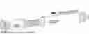
FIG. 1 is a schematic structural diagram of a bubble blowing mechanism in some embodiments of the present disclosure.
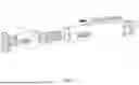
FIG. 2 is a schematic structural diagram of the bubble blowing mechanism shown in FIG. 1 from another perspective.
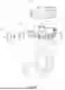
FIG. 3 is an exploded view of the bubble blowing mechanism in some embodiments of the present disclosure.
FIG. 4 is a partial schematic structural diagram of the bubble blowing mechanism shown in FIG. 3.
FIG. 5 is an exploded view of a partial structure of a bubble machine in some embodiments of the present disclosure.
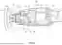
FIG. 6 is a schematic diagram of an internal structure of the bubble blowing mechanism in some embodiments of the present disclosure.
DESCRIPTION OF EMBODIMENTS
The implementation modes of the present disclosure will be described in more detail below with reference to the accompanying drawings. Although the embodiments of the present disclosure are shown in the accompanying drawings, it should be understood that the present disclosure can be implemented in various forms and should not be limited by the embodiments described herein. On the contrary, these embodiments are provided to render the present disclosure more thorough and complete, and to fully convey the scope of the present disclosure to those skilled in the art.
It should be understood that although terms “first”, “second”, “third”, etc. may be used in the present disclosure to describe various information, these terms should not be limited to them. These terms are only used to distinguish information of the same type from each other. For example, without departing from the scope of the present disclosure, a first information may also be referred to as a second information, and similarly, the second information may also be referred to as the first information. Thus, the features limited to “first” and “second” may explicitly or implicitly include one or more of these features. In the description of the present disclosure, the meaning of “multiple” refers to two or more, unless otherwise specified.
In the description of the present disclosure, it should be understood that terms “length”, “width”, “up”, “down”, “front”, “back”, “left”, “right”, “vertical”, “horizontal”, “top”, “bottom”, “inside”, “outside” and other directional or positional relationships indicated are based on the directional or positional relationships shown in the accompanying drawings, only for the convenience of describing the present disclosure and simplifying the description, and do not indicate or imply that the device or component referred to must have a specific orientation, be constructed and operated in a specific orientation, and therefore cannot be understood as a limitation of the present disclosure.
Unless otherwise specified and limited, terms “installation”, “connection with”, “connection to”, “fixation”, etc. should be broadly understood, for example, it can be a fix connection, a detachable connection, or integrated; it can be a mechanical connection or an electrical connection; it can be directly connected or indirectly connected through an intermediate medium, and it can be a connection within two components or an interaction relationship between two components. For those skilled in the art, specific meanings of the above terms in the present disclosure can be understood according to a specific situation.
FIGS. 1 and 2 show a bubble blowing mechanism in some embodiments of the present disclosure, which is used to blow out bubbles. The bubble blowing mechanism includes a housing 1, a driving device 2, a pumping liquid device 3, a bubbling device 7, and a fan blade 4. The driving device 2 is provided on the housing 1; the fan blade is connected to the driving device 2. The pumping liquid device 3 is provided on the housing 1, and the pumping liquid device 3 is connected to the driving device 2.
It can be understood that housing 1 plays a role in installation and load-bearing. The driving device 2 is used to output torque. The pumping liquid device 3 is used for pumping liquids. The fan blade 4 is used to drive gas to flow when it is rotated. The bubbling device 7 is used to generate a bubble film, thereby producing bubbles when the airflow blows through.
As shown in FIGS. 2 to 6, the bubble device 7 includes a bubble nozzle 71, a transmission shaft 72, and a foaming liquid stirring element 73. The bubble nozzle 71 is provided on the housing 1 and is communicated to the pumping liquid device 3. One end of the transmission shaft 72 is connected to the driving device 2, and the other end of the transmission shaft 72 is connected to the foaming liquid stirring element 73. The foaming liquid stirring element 73 is rotatably provided in the bubble nozzle 71. The bubble nozzle 71 includes a bubble outlet 713 with a gradually decreasing cross-sectional area in a direction of bubble formation, and the bubble outlet 713 is a funnel structure; when the fan blade 4 is rotated, it drives airflow into the bubble nozzle 71 and flows out through the foaming liquid stirring element 73 and the bubble outlet 713.
It should be noted that one end of the transmission shaft 72 is connected to the driving device 2 to receive torque, and the other end thereof is extended to an interior of the bubble nozzle 71 and is connected to the foaming liquid stirring element 73 to drive the foaming liquid stirring element 73 to rotate. The foaming liquid stirring element 73 is located in the bubble nozzle 71, which plays the role of stirring bubble liquid to ensure produced bubbles are fine and even. In particular, since the sectional area of the bubble outlet 713 in the foaming direction gradually decreases, the bubbles will gradually gather in a process of moving in the bubble outlet 71 to avoid an expansion of the bubble film, thus rendering blown bubbles more dense, concentrated and continuous.
As shown in FIGS. 2 to 6, in some embodiments of the bubble blowing mechanism 10, the driving device 2 includes a dual axis motor 21 and a gear transmission assembly. The dual axis motor 21 is provided on the housing 1, the gear transmission assembly is provided in the housing 1. A first driving shaft 211 of the dual axis motor 21 is provided at one end away from the bubble nozzle 71 and parallel to the bubble nozzle 71. The first driving shaft 211 is connected to the gear transmission assembly, which is connected to one end of the transmission shaft, and the other end of the transmission shaft is connected to the foaming liquid stirring element 73; the pumping liquid device 3 is connected to the gear transmission assembly.
It can be understood that the dual axis motor 21 is fixedly provided on the housing 1 and has two independently controlled driving shafts. The gear transmission assembly is an existing technology that can be configured to include multiple sequentially meshing gears, thereby transmitting a torque of the dual axis motor 21 at a predetermined transmission ratio and predetermined path. One end of the transmission shaft is connected to the gear transmission assembly, and the other end thereof is extended to the interior of the bubble nozzle 71 and is connected to the foaming liquid stirring element 73 so as to drive the foaming liquid stirring element 73 to rotate.
As shown in FIGS. 2 to 6, in some embodiments of the bubble blowing mechanism 10, the gear transmission assembly includes a pump gear 23, a transmission gear 24, and at least one reduction gear 22.
The first driving shaft 211 of the dual axis motor 21 is connected to the reduction gear 22, the reduction gear 22 is engaged with the pump gear 23. The pump gear 23 is engaged with the transmission gear 24. One end of the transmission shaft is connected to the transmission gear 24, and the other end of the transmission shaft is connected to the foaming liquid stirring element 73. The pumping liquid device 3 is connected to the pump gear 23.
It can be understood that the reduction gear 22 is provided in the housing 1 and can freely rotate around its own axis. The first driving shaft 211 of the dual axis motor 21 is connected to the reduction gear 22 through a suitable mechanical connection (such as keyway fitting) to transmit power. The reduction gear 22 is further engaged with the pump gear 23 to form a next power transmission chain. The pump gear 23 is further engaged with transmission gear 24 to achieve torque conversion.
It should be noted that the pumping liquid device 3 is directly provided on the pump gear 23. When the pump gear 23 is rotated, the pumping liquid device 3 acts accordingly to extract the bubble liquid and push it to the bubble nozzle 71.
As shown in FIGS. 2 to 6, in some embodiments of the bubble blowing mechanism 10, the driving device 2 further includes two torque transmission sleeves 27, one of which is provided on the transmission gear 24, and the other torque transmission sleeve 27 is provided on the foaming liquid stirring element 73.
Two ends of the transmission shaft are provided with a torque transmission part, and two torque transmission parts are correspondingly connected to the two torque transmission sleeves 27.
It can be understood that by a cooperation between the torque transmission part and the torque transmission sleeves, which plays a transmission role, it can also solve a problem of connecting two torque transmission parts that are not on the same horizontal line.
It can be understood that the two torque transmission sleeves 27 both play a role in transmission. When the transmission gear 24 is rotated, it drives the torque transmission sleeves 27 to rotate, thereby driving the transmission shaft to rotate through the torque transmission part. A rotation of the transmission shaft will drive another torque transmission sleeve 27 to rotate through another torque transmission part, thereby driving a stirring element 26 to rotate.
As shown in FIGS. 2 to 6, in some embodiments of the bubble blowing mechanism 10, each of the torque transmission sleeves 27 is provided with a hexagonal hole 271, and each of the torque transmission parts includes a nut 722. Two ends of the transmission shaft are provided with bolts 721, and two nuts 722 are screwed onto the two bolts 721 one by one, and each of the nuts 722 is inserted into two hexagonal holes 271 one by one.
It can be understood that a size of the hexagonal hole 271 matches outer diameters of the nuts 722, ensuring that the nuts 722 can be securely inserted into it. The torque transmission part includes one nut 722. The nut 722 has internal threads for screwing with the bolt 721 at an end of the transmission shaft. The two ends of the transmission shaft are respectively provided with bolts 721. The bolts 721 have external threads that match the internal threads of the nuts 722.
It should be noted that the nuts 722 and the bolts 721 can be configured as a fixed connection, which can be locked by threads, or clamped and fixed by welding, bonding, or other clamping structures to fix relative position and angle of the nuts 722 and the transmission shaft, ensuring that the torque can be effectively fixed through the nuts 722. In other ways, a non-threaded cylinder can be used instead of the bolts 721, and a hexagonal structure that can be adapted to the hexagonal hole 271 can be provided on the cylinder, which can also achieve the purpose of torque transmission by being placed in the hexagonal hole 271.
As shown in FIGS. 2 to 6, in some embodiments of the bubble blowing mechanism 10, the driving device 2 includes two transmission gears 24.
The driving device 2 further includes a transmission bevel gear 28 and a connection shaft 29. One end of the connection shaft 29 is connected to the transmission bevel gear 28, the transmission bevel gear 28 is engaged with the pump gear 23. The other end of the connection shaft 29 is connected to one of the transmission gears 24. The torque transmission sleeves 27 are provided on the other transmission gear 24, and the two transmission gears 24 are engaged with each other.
It can be understood that the two transmission gears 24 are engaged with each other to form a gear assembly. This gear assembly can change power transmission direction and adjust speed and torque through an appropriate gear ratio to meet different work requirements.
The transmission bevel gear 28 is engaged with the pump gear 23, ensuring that the power from the pump gear 23 can be smoothly turned and transmitted to the connection shaft 29. One end of the connection shaft 29 is fixedly connected to the transmission bevel gear 28, and the other end thereof is connected to one of the transmission gears 2, thus forming a power transmission path from the pump gear 23 to the transmission gear 24. The torque transmission sleeves 27 are provided on another transmission gear 24 that is not directly connected to the connection shaft 29. In this way, torque can be transmitted to the torque transmission sleeves 27 through the pump gear 23. As shown in FIGS. 1 to 6, in some embodiments of the bubble blowing mechanism of the present disclosure, the torque transmission sleeves 27 and the transmission gear 24 are integrally formed structures.
It can be understood that the torque transmission sleeve 27 and the transmission gear 24, which are integrally formed together, have higher connection strength, thereby improving the durability of the product.
As shown in FIGS. 2 to 6, in some embodiments of the bubble blowing mechanism 10, the housing 1 is provided with an air chamber 51 and an air duct 52. The fan blade 4 is located in the air chamber 51, and the air duct 52 is respectively connected to the air chamber 51 and the bubble nozzle 71 respectively. The transmission shaft passes through the air duct 52.
It can be understood that the air chamber 51 has an inlet for air flow to accommodate the fan blade 4. The air duct 52 is a channel connecting the air chamber 51 and the bubble nozzle 71. The air chamber 51 provides a relatively enclosed working environment for the fan blade 4, enabling it to effectively generate airflow when it is rotated.
The fan blade 4 is located in the air chamber 51 and is driven to rotate by a second drive shaft 212 of the dual axis motor 21, thereby generating a stable airflow. Through the air duct 52, the air flow can bring the bubble liquid delivered from the pumping liquid device 3 out of the bubble nozzle 71 to form continuous and uniform bubbles.
As shown in FIGS. 2 to 6, in some embodiments of the bubble blowing mechanism 10, the pumping liquid device 3 includes a pump body 32 and an infusion tube. The pump body 32 is connected to the gear transmission assembly, and the bubble liquid is pumped to the bubble nozzle 71 through the infusion tube.
It can be understood that after the pump body 32 receives torque and operates, it will continuously pump the bubble liquid into the bubble nozzle 71 through the infusion tube.
As shown in FIGS. 2 to 6, in some embodiments of the bubble blowing mechanism 10, the bubble nozzle 71 is cylindrical, and the bubble nozzle 71 is further provided with a bubble joint 711 and a liquid guide channel 712. The pump body 32 is communicated to the bubble joint 711, and the bubble joint 711 is connected and guides the bubble liquid to the liquid guide channel 712, so that the bubble liquid is guided to the foaming liquid stirring element 73 through the liquid guide channel 712. When the airflow flows through the foaming liquid stirring element 73, bubbles are formed and discharged through the bubble outlet 713.
It can be understood that the bubble nozzle 71 is in a cylindrical shape as a whole, which facilitates a smooth passage of the air flow and a uniform distribution of the bubble liquid. The bubble joint 711 is located at one end of the bubble nozzle 71 and is used to communicate with the pump body 32. The bubble joint 711 receives bubble liquid from the pump body 32 and introduces it into the bubble nozzle 71. The liquid guide channel 712 is connected with the bubble joint 711 and the bubble outlet 713, which is a flow path of the bubble liquid in the bubble nozzle 71. The bubble outlet 713 is located at the other end of the bubble nozzle 71, which is a place where the bubbles are finally discharged. The bubble outlet 713 is used to discharge the bubbles.
As shown in FIGS. 1 to 6, the bubble machine includes the bubble blowing mechanism 10, a liquid storage unit 8, and a power supply unit 9. The housing 1 includes a main body 11 and an inner housing 12, the inner housing 12 is provided in the main body 11. The driving device 2, the pumping liquid device 3, the bubbling device 7, and the fan blade 4 are respectively provided in the inner housing 12. The bubbling device 7 is connected to the main body 11, and the main body 11 is provided with a grip part 111.
The inner housing 12, the grip part 111, the liquid storage unit 8, and the power supply unit 9 are sequentially provided radially on the main body 11. The liquid storage unit 8 is connected to the pumping liquid device 3, and the power supply unit 9 is electrically connected to the driving device 2; the main body 11 is further provided with a hanging piece 13.
It can be understood that the liquid storage unit 8 is used to contain liquid used for blowing bubbles. The power supply unit 9 is used to transmit electrical energy to the driving device 2. The hanging piece 13 is used to hang and fix the product.
As shown in FIGS. 1 to 6, in some embodiments of the bubble blowing mechanism of the present disclosure, the bubble machine further includes a control switch 6, which is electrically connected to the dual axis motor 21.
It can be understood that the control switch 6 is provided in an easily operable position on the housing 1, such as an end face, a side face, or other convenient operating position of the housing 1. The control switch 6 is electrically connected to the dual axis motor 21 through wires or other appropriate electrical connections, so that a user can control start, stop, and operation states of the dual axis motor 21 by operating the control switch 6.
It should be noted that the control switch 6 can be directly connected to the dual axis motor 21 or connected through a circuit board.
The implementation of the present disclosure have at least the following beneficial effects.
The present disclosure relates to a bubble blowing mechanism and a bubble machine, where the bubble machine is provided with the bubble blowing mechanism. In the bubble blowing mechanism, the foaming liquid stirring element is rotated continuously under an action of the driving device, which can effectively stir bubbles to ensure that produced bubbles are fine and even. High quality bubbles not only increase the visual beauty, but also improve the durability and stability of the bubbles. A bubble outlet is configured to be a funnel structure with gradually reduced cross-sectional area, so that the bubbles are gradually compressed and concentrated during a formation process. This feature helps to control the size and shape of the bubbles, reduce the random dispersion of bubbles, and is conducive to manufacturing bubbles with specific shapes or patterns.
The technical scheme of the present disclosure has been described in detail with reference to the accompanying drawings in the specification. In the above embodiments, the description of each embodiment has its own emphasis. For the parts that are not described in detail in one embodiment, please refer to the relevant descriptions of other embodiments. Those skilled in the art should also be aware that the actions and modules mentioned in the specification are not necessarily necessary for the present disclosure. Furthermore, it can be understood that steps in the method of the embodiment of the present disclosure can be sequentially adjusted, merged, and deleted according to an actual need, and the modules in the device of the embodiments of the present disclosure can be merged, divided, and deleted according to the actual need.
The above has described various embodiments of the present disclosure. The above description is exemplary, not exhaustive, and is not limited to the disclosed embodiments. Without deviating from the scope and spirit of the various embodiments described, many modifications and changes are obvious to those skilled in the art. The selection of terms used in this specification aims to best explain the principles, practical applications, or improvements to the technology in the market of each embodiment, or to enable other ordinary technical personnel in this field to understand the various embodiments disclosed in this specification.
Claims
What is claimed is:1. A bubble blowing mechanism, comprising:
a housing;
a driving device, provided on the housing;
a pumping liquid device, provided on the housing and connected to the driving device;
a bubbling device, comprising a bubble nozzle, a transmission shaft, and a foaming liquid stirring element; wherein the bubble nozzle is provided on the housing and is communicated to the pumping liquid device; one end of the transmission shaft is connected to the driving device, and the other end of the transmission shaft is connected to the foaming liquid stirring element; the foaming liquid stirring element is rotatably provided in the bubble nozzle; the bubble nozzle comprise a bubble outlet having a gradually decreasing cross-sectional area in a direction of bubble formation; the bubble nozzle is a funnel structure; and
a fan blade, connected to the driving device, when the fan blade is rotated, it drives airflow into the bubble nozzle and flow out through the foaming liquid stirring element and the bubble outlet.
2. The bubble blowing mechanism according to claim 1, wherein the driving device comprises a dual axis motor and a gear transmission assembly,
the dual axis motor is provided on the housing,
the gear transmission assembly is provided in the housing;
a first driving shaft of the dual axis motor is provided at one end away from the bubble nozzle and parallel to the bubble nozzle,
the first driving shaft is connected to the gear transmission assembly,
the gear transmission assembly is connected to one end of the transmission shaft, and the other end of the transmission shaft is connected to the foaming liquid stirring element;
the pumping liquid device is connected to the gear transmission assembly.
3. The bubble blowing mechanism according to claim 2, wherein the gear transmission assembly comprises a pump gear, a transmission gear, and at least one reduction gear;
the first driving shaft of the dual axis motor is connected to the reduction gear, the reduction gear is engaged with the pump gear;
the pump gear is engaged with the transmission gear;
one end of the transmission shaft is connected to the transmission gear, and the other end of the transmission shaft is connected to the foaming liquid stirring element;
the pumping liquid device is connected to the pump gear.
4. The bubble blowing mechanism according to claim 3, wherein the driving device further comprises two torque transmission sleeves, one of which is provided on the transmission gear, and the other one is provided on the foaming liquid stirring element;
two ends of the transmission shaft are respectively provided with a torque transmission part, two torque transmission parts are correspondingly connected to the two torque transmission sleeves.
5. The bubble blowing mechanism according to claim 4, wherein each of the torque transmission sleeves is provided with a hexagonal hole, each of the torque transmission parts comprises a nut, and two ends of the transmission shaft are provided with bolts; two nuts are screwed onto two bolts one by one, and each of the nuts is inserted into two hexagonal holes one by one.
6. The bubble blowing mechanism according to claim 3, wherein the driving device comprises two transmission gears;
the driving device further comprises a transmission bevel gear and a connection shaft;
one end of the connection shaft is connected to the transmission bevel gear, the transmission bevel gear is engaged with the pump gear; the other end of the connection shaft is connected to one transmission gear;
the torque transmission sleeves are provided on the other one transmission gear, and the two transmission gears are engaged with each other.
7. The bubble blowing mechanism according to claim 2, wherein the housing is provided with an air chamber and an air duct;
the fan blade is located in the air chamber, and the air duct is respectively connected to the air chamber and the bubble nozzle; the transmission shaft passes through the air duct.
8. The bubble blowing mechanism according to claim 2, wherein the pumping liquid device comprises a pump body and an infusion tube,
the pump body is connected to the gear transmission assembly, and bubble liquid is pumped to the bubble nozzle through the infusion tube.
9. The bubble blowing mechanism according to claim 8, wherein the bubble nozzle is cylindrical, and the bubble nozzle is further provided with a bubble joint and a liquid guide channel;
the pump body is communicated to the bubble joint, and the bubble joint is connected to and guides the bubble liquid to the liquid guide channel, so that the bubble liquid is guided to the foaming liquid stirring element through the liquid guide channel, and when the airflow flows through the foaming liquid stirring element, bubbles are formed and discharged through the bubble outlet.
10. A bubble machine, comprising the blowing mechanism according to claim 9, a liquid storage unit and a power supply unit;
the housing comprises a main body and an inner housing, wherein the inner housing is provided in the main body,
the driving device, the pumping liquid device, the bubbling device, and the fan blade are respectively provided in the inner housing;
the bubbling device is connected to the main body, and the main body is provided with a grip part;
the inner housing, the grip part, the liquid storage unit, and the power supply unit are sequentially provided radially on the main body; the liquid storage unit is communicated to the pumping liquid device, and the power supply unit is electrically connected to the driving device;
wherein the main body is further provided with a hanging piece.
Images & Drawings included:


Sources:
- United States Patent and Trademark Office - verify current appl. status at the USPTO↗
Recent applications in this class:
- » 20260061333 2026-03-05
Bubble blowing device - » 20260034474 2026-02-05
WIND-DRIVEN BUBBLE GENERATING DEVICE AND APPLICATION THEREOF - » 20260021425 2026-01-22
BUBBLE MACHINE - » 20260007982 2026-01-08
BUBBLE BLOWING DEVICE - » 20250387722 2025-12-25
Vertical Bubble Machine - » 20250352923 2025-11-20
INTERACTIVE BUBBLE TUBE FIXTURE - » 20250332523 2025-10-30
BUBBLE-BLOWING TOY - » 20250332522 2025-10-30
BUBBLE-BLOWING TOY - » 20250249373 2025-08-07
Dense bubble generator - » 20250153069 2025-05-15
CUSTOMIZABLE BUBBLE CANNON