VEHICLE CRASH CUSHION
US20260125864A1
2026-05-07
19/381,175
2025-11-06
Smart Summary: A crash cushion is designed to absorb energy when a vehicle hits it. It consists of several supports and energy-absorbing modules that work together to reduce the impact. The modules have plates that can bend and compress, helping to lessen the force of the collision. These plates are arranged in a way that allows them to stretch and compress during an impact. Overall, the crash cushion helps protect both vehicles and people by reducing the severity of crashes. 🚀 TL;DR
Abstract:
A crash cushion for absorbing energy when impacted by a vehicle includes a number of supports, a number of energy absorbing modules, a front anchor structure, a rear anchor structure, and a pair of elongated rails extending from the front anchor structure to each of the plurality of supports and to the rear anchor. Each of the energy absorbing modules includes first and second longitudinally extending plates positioned between a pair of the support plates and a first laterally extending plate positioned between and attached to the first and second longitudinally extending plates. The first and second longitudinally extending plates and the first laterally extending plate each have a hinge section about which they compress or stretch to absorb impact forces.
Inventors:
- Marco Anghileri 10 🇮🇹 Milan, Italy
- Valeria Di Giacomo 1 🇮🇹 Trezzo sull’Adda Milano, Italy
- Augusto Piccinini 1 🇮🇹 Trezzo sull’Adda Milano, Italy
Applicant:
Interested in similar patents?
Get notified when new applications in this technology area are published.
Classification:
E01F15/146 » CPC main
Safety arrangements for slowing, redirecting or stopping errant vehicles, e.g. guard posts or bollards; Arrangements for reducing damage to roadside structures due to vehicular impact specially adapted for local protection, e.g. for bridge piers, for traffic islands; Means for vehicle stopping using impact energy absorbers fixed arrangements
E01F15/14 IPC
Safety arrangements for slowing, redirecting or stopping errant vehicles, e.g. guard posts or bollards; Arrangements for reducing damage to roadside structures due to vehicular impact specially adapted for local protection, e.g. for bridge piers, for traffic islands
Description
CROSS-REFERENCE TO RELATED APPLICATION
The current patent application is a non-provisional utility patent application which claims priority benefit, with regard to all common subject matter, of earlier-filed U.S. Provisional Application Ser. No. 63/717377; titled “VEHICLE CRASH CUSHION”; and filed November 7, 2024. The Provisional Application is hereby incorporated by reference, in its entirety, into the current patent application.
BACKGROUND
Crash cushions, also known as impact attenuators or crash barriers, absorb and reduce impact forces when vehicles collide with guardrails, bridge supports, roadside barriers, and other rigid structures on or near roadways. They are typically placed in front of these rigid structures in locations where there is a high risk of vehicle crashes, such as highway exits, intersections, or construction zones. The crash cushions attempt to minimize the severity of collisions by providing a controlled deceleration path for impacting vehicles, thereby reducing the likelihood of injury to vehicle occupants and damage to the impacting vehicles and the structures protected by the crash cushions.
One type of crash cushion includes a number of fluid filled barrels or other energy absorbing modules placed in front of a structure to be protected. This type of crash cushion is configured to collapse upon itself when subjected to a frontal vehicle impact to transfer and absorb vehicle impact energy. When subjected to a side vehicle impact, the crash cushion is configured to redirect the vehicle away from the structure being protected.
Unfortunately, these types of crash cushions and other known crash cushions suffer from several disadvantages that limit their utility. For example, the energy absorbing modules in these crash cushions have inconsistent deformation profiles that cascade with stronger impacts. Moreover, lateral movement of the energy absorbing modules near the structure being protected, whether from side vehicle impacts or straight-on vehicle impacts, leads to vehicle instability and poor crash cushion performance, especially for high force impacts.
The background discussion is intended to provide information related to the present invention which is not necessarily prior art.
SUMMARY
The present invention solves the above-described problems and related problems by providing an improved crash cushion that exhibits superior deformation properties, that limits lateral movement of the crash cushion, and that provides other related advantages.
A crash cushion constructed according to an embodiment of the invention broadly includes a plurality of spaced apart supports; a plurality of energy absorption modules sandwiched between the supports; a front anchor structure; a rear anchor structure; and at least one elongated rail extending from the front anchor structure to each support and to the rear anchor structure. Some embodiments of the crash cushion may also comprise a number of side panels interconnecting the supports and enveloping the energy absorbing modules.
In some embodiments, the supports are plates formed of steel, aluminum sheet metal or other suitable rigid materials and are spaced apart along a longitudinal axis of the crash cushion. Each support occupies a vertical plane that extends along an axis perpendicular to the longitudinal axis of the cushion. The crash cushion may include any number of supports, and the supports may be any size.
At least one energy absorption module is sandwiched between each adjacent pair of supports. The energy absorbing modules are designed to crush in a coordinated fashion when an impacting vehicle strikes the front or sides of the crash cushion. Any total number of energy absorption modules may be provided in the crash cushion and any number of them may be sandwiched between each adjacent pair of supports.
In one embodiment, the energy absorption modules are formed of steel, aluminum sheet metal or other suitable rigid materials. Each energy absorption module comprises first and second longitudinally extending plates and a first laterally extending plate.
The longitudinally extending plates extend along an axis parallel to the longitudinal axis of the crash cushion and are spaced apart about an axis transverse to the longitudinal axis of the crash cushion. The longitudinally extending plates include opposed outwardly protruding hinge sections. In one embodiment, the hinge sections comprise bends in the plates.
One laterally extending plate is positioned between each pair of first and second longitudinally extending plates. In one embodiment, the laterally extending plate is oriented horizontally, and in other embodiments it is oriented vertically. The laterally extending plate also has a hinge section. In one embodiment, the hinge section comprises one or more bends in the plate.
When the crash cushion is struck by an impacting vehicle, the supports are pushed together toward the rigid structure being protected, compressing the energy absorption modules to absorb the impact forces. As each energy absorption module is compressed, its longitudinally extending plates compress about their hinge sections and its laterally extending plate compresses or stretches about its hinge section to moderate the compression of the longitudinally extending plates. The laterally extending plate also provides a limit to the compression of the longitudinally extending plates before additional hinges in the longitudinal extending plates are activated or created through buckling. The compression of the longitudinally extending plates and the compression or stretching of the laterally extending plate provide a controlled attenuation of the collision forces from the impacting vehicle.
This summary is provided to introduce a selection of concepts in a simplified form that are further described below in the detailed description. This summary is not intended to identify key features or essential features of the claimed subject matter, nor is it intended to be used to limit the scope of the claimed subject matter. Other aspects and advantages of the present invention will be apparent from the following detailed description of the embodiments and the accompanying drawing figures.
DRAWING DESCRIPTION
Embodiments of the present invention are described in detail below with reference to the attached drawing figures. The drawing figures do not limit the present invention to the specific embodiments disclosed and described herein. The drawings are not necessarily to scale, emphasis instead being placed upon clearly illustrating the principles of the invention.
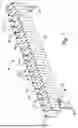
FIG. 1 is a top perspective view of a crash cushion constructed in accordance with embodiments of the present invention.
FIG. 2 is a bottom perspective view of the crash cushion of FIG. 1.
FIG. 3 is a top view of the crash cushion of FIG. 1.
FIG. 4 is a sectional view of the crash cushion taken along line 4/4 of FIG. 3.
FIG. 5 is a top perspective view of a crash cushion constructed in accordance with other embodiments of the present invention.
FIG. 6 is a top perspective view of a portion of a crash cushion constructed in accordance with other embodiments of the present invention.
FIG. 7 is a bottom perspective view of the crash cushion of FIG. 6.
FIG. 8 is a top view of the crash cushion of FIG. 6.
FIG. 9 is a top perspective view of a portion of a crash cushion constructed in accordance with other embodiments of the present invention.
FIG. 10 is a bottom perspective view of the crash cushion of FIG. 9.
FIG. 11 is a top view of the crash cushion of FIG. 9.
DETAILED DESCRIPTION
Crash cushions constructed in accordance with embodiments of the invention are illustrated in the attached drawing figures. The crash cushions may be installed adjacent rigid structures such as pillars, bridge abutments, lighting poles, or the like for absorbing vehicle impact energy and minimizing the effects of impact on the vehicles, the vehicles’ occupants, and the structures being protected.
A crash cushion 10 constructed in accordance with one embodiment of the invention is depicted in FIGS. 1- 4 and broadly comprises a number of spaced-apart supports 12; energy absorbing modules 14 positioned between the supports 12; a front anchor structure 16; a rear anchor structure 18; and a pair of elongated rails 20, 22 extending between the anchors 16, 18 and through at least some of the supports 12. The crash cushion 10 may also include a substantially immovable support frame (not shown) attached to the rear anchor structure 18 and a front impact member or nose 24 located at the forward end of the crash cushion 10. Embodiments of each of these components will now be described in more detail.
The supports 12 are spaced along a longitudinal axis of the crash cushion 10 and, except for the support closest to the rear anchor structure 18, are configured to telescopically slide and collapse toward the rear anchor structure 18 and the rigid structure protected by the crash cushion when the front of the crash cushion is struck by a vehicle. The supports 12 also cooperate with other components of the crash cushion to redirect a vehicle away from the crash cushion and the structure being protected when either side of the crash cushion is struck by a vehicle. The crash cushion may include any number of supports 12 to support any number of energy absorption modules 14 so that the crash cushion 10 may be designed to absorb any amount of impact forces.
In one embodiment, the supports 12 are rigid planar plates formed of steel, aluminum sheet metal, or other suitable rigid materials and are approx. 2-6 feet long, 2-4 feet tall, and 1/16 – ½ inches thick. As labeled in FIG. 2, two notches or holes 26, 28 are formed near the lower edge of each of the supports through which the rails 20, 22 extend. Angle brackets 30 or other plates are bolted, welded, or otherwise attached or formed into the lowermost edges of the supports 12 to serve as ground-engaging skid plates. The skid plates prevent the supports 12 and other components of the crash cushion from contacting the ground during vehicle impacts. This reduces the likelihood of an impacting vehicle driving over the supports and facilitates controlled crushing of the supports. The skid plates 30 also minimize snagging of the supports on unlevel or damaged roadway surfaces. The skid plate on the frontmost support also provides a contact point with the underside of an impacting vehicle to limit lifting of the support plate to prevent an impacting vehicle from going under the crash cushion.
The energy absorption modules 14 are positioned between the supports 12 and provide the primary impact absorption properties of the crash cushion 10. In the illustrated embodiment, the energy absorption modules 14 are aligned between the supports 12 along the longitudinal axis of the crash cushion, but they may be staggered or positioned anywhere between the supports. Any number of supports 12 and energy absorbing modules 14 may be provided to form a crash cushion of any desired length and crash rating. Several embodiments of the energy absorption modules are described in more detail below.
The front anchor structure 16 is partially encased in or otherwise fixed to a ground surface in front of the forwardmost portion of the crash cushion and is essentially immovable. To that end, the front anchor structure 16 may include or be bolted to blocks or slabs of concrete embedded in the ground. The front anchor structure 16 may be a steel I-beam with anchor points for anchoring the rails 20, 22 via bolts or the like. In the illustrated embodiment, the front anchor structure includes a single I-beam, but it may include any number of I-beams or other anchor structures.
Similarly, the rear anchor structure 18 is fixed in position near the rigid structure being shielded and is also essentially immovable. The rear anchor structure 18 may include or be bolted to blocks or slabs of concrete embedded in the ground. An immoveable support frame may be bolted to, integrally formed with, or otherwise fixedly secured to the rear anchor structure 18. In one embodiment, the rear anchor structure 18 may be a steel I-beam with anchor points for receiving and anchoring the rails 20, 22. In the illustrated embodiment, the rear anchor structure includes two steel I-beams, but it may include any number of I-beams or other anchor structures.
The rails 20, 22 extend between the front and rear anchor structures 16, 18 and through the notches 26, 28 formed in the supports 12. The rails may be any combination of metal tubes, cables, or other elongated structures. Although two rails are shown, any number of rails may be provided.
The rails 20, 22 and anchor structures 16, 18 limit sideways or lateral movement of the crash cushion 10 during a vehicle impact. The rails and anchor structures also maintain the upright orientation of the supports 12 and keep them from rotating about their vertical axes and/or falling down when moving rearward responsive to a frontal impact on the crash cushion or moving sideways responsive to a side impact so as to facilitate controlled collapse of the supports and/or redirection of a vehicle during vehicle impacts.
The nose 24 is the forwardmost portion of the crash cushion and is the initial impact point for vehicles that impact the crash cushion from the front. The nose may be made of the same materials as the supports 12 but in some embodiments doesn’t extend all the way to the ground. In one embodiment, the impact nose or plate may be formed of polymer materials and the remainder of the crash cushion formed of sheet metal.
Several embodiments of the energy absorption modules 14 will now be described in more detail.
The energy absorption modules 14 in the crash cushion 10 depicted in FIGS. 1-4 each comprises first and second longitudinally extending plates 40, 42 and a laterally extending plate 44. The plates 40, 42, 44 may be formed of aluminum sheet metal or other suitable rigid materials.
Two of the longitudinally extending plates 40, 42 are supported on opposite ends of each pair of adjacent supports 12 and extend generally parallel to the longitudinal axis of the crash cushion. Each plate 40, 42 includes bent end sections 46 that are bolted to, welded to, or otherwise attached to or integrally formed with the supports. Each pair of longitudinally extending plates also include opposed outwardly protruding bends 48, 50 that form hinge sections, the operation of which is described below.
Each laterally extending plate 44 is positioned between two of the longitudinally extending plates 40, 42 and is attached to an adjacent pair of the supports 12. In the illustrated embodiment, the laterally extending plates are oriented horizontally, but they may extend vertically. As shown in FIG. 4, the plates 44 are attached above the vertical midpoints of the longitudinally extending plates 40, 42. In one embodiment, the plates 44 are attached near the upper 1/3 of the longitudinally extending plates 40, 42 so as to be near the midpoint of a typical automobile.
Each laterally extending plate 44 has at least one bend 52 that forms a hinge section about which the plate crushes during vehicle impacts. Resistance to the deformation of the longitudinal plates 40, 42 is increased by bending of the lateral plates 44 about their hinge sections, keeping the overall force resistance of the energy absorption module consistent as it is deformed.
In use, the crash cushion 10 may be positioned in front of an obstacle, hazard, or any rigid structure with the front anchor structure 16 and rear anchor structure 18 secured to the ground surface via fasteners or the like. A vehicle impacting the crash cushion 10 may force the supports 12 rearward (toward the obstacle or hazard) so that at least some of the energy absorbing modules 14 collapse in a coordinated fashion to dissipate impact forces from the impacting vehicle. When struck, the support plates 12 are pushed together, compressing the energy absorption modules 14 to absorb the impact forces.
As each energy absorption module 14 is compressed, its longitudinally extending plates 40, 42 compress about their hinge sections 48, 50 and its laterally extending plate 44 compresses about its hinge sections 52 to moderate the compression of the longitudinally extending plates 40, 42.
As the longitudinal plates 40, 42 and lateral plates 44 deform during an impact, the force required to continue deformation gradually decreases as they are crushed. The longitudinal and lateral plates work together to create a more consistent energy absorption force profile.
A crash cushion 10A constructed in accordance with another embodiment of the invention is depicted in FIG. 5. The crash cushion 10A is substantially identical to the crash cushion 10 depicted in FIGS. 1-4 with similar components identified by the same reference numerals followed by “A”. The primary difference between the crash cushion 10A is that its energy absorption modules 14A include only longitudinally extending plates 40A, 42A and no laterally extending plates.
Portions of a crash cushion 10B constructed in accordance with another embodiment of the invention are depicted in FIGS. 6-8. The crash cushion 10B is similar to the crash cushion 10 depicted in FIGS. 1-4 with similar components identified by the same reference numerals followed by “B”. The primary difference between the crash cushion 10B and the crash cushion 10 is the construction of the energy adsorption modules 14B and the addition of side panels 54B.
The energy absorption modules 14B of the crash cushion 10B each comprises first and second longitudinally extending plates 40B, 42B and a laterally extending plate 44B. The plates 40B, 42B, 44B as well as the side panels 54B may be formed of steel, aluminum sheet metal, or other suitable rigid materials.
Two of the longitudinally extending plates 40B, 42B are attached between each pair of adjacent supports 12B and extend generally parallel to the longitudinal axis of the crash cushion. Each plate 40B, 42B includes ends 46B that are welded to or otherwise attached to the supports 12B. Each longitudinally extending plate also includes an outwardly protruding bend 48B, 50B that forms a hinge section. The bends 48B, 50B of adjacent plates 40B, 42B oppose one another.
The laterally extending plate 44B of each energy absorption module 14B extends transversely between two of the longitudinally extending plates 40B, 42B with ends that connect with the bends 48B, 50B in the plates 40B, 42B. In the illustrated embodiment, the laterally extending plates are oriented vertically, but they may be oriented horizontally.
Each laterally extending plate 44B includes a four-walled, diamond-shaped central section 56B and a pair of planar end sections 58B extending from the central section 56B. The diamond-shaped central section 56B forms a hinge.
The side panels 54B interconnect the supports 12B and envelop the energy absorbing modules 14B. Each side panel is bolted, rivetted, welded or otherwise attached to two of the supports 12B. The middle of each side panel 54B may have a bend 56B or perforated region that forms a hinge which meets the ends of one of the laterally extending plates 44B.
In use, the crash cushion 10B may be positioned in front of an obstacle or hazard as described above. A vehicle impacting the crash cushion 10B may force the supports 12B rearward (toward the obstacle or hazard) so that at least some of the energy absorbing modules 14B collapse in a coordinated fashion to dissipate impact forces from the impacting vehicle. When struck, the support plates 12B are pushed together, compressing the energy absorption modules 14B to absorb the impact forces.
As each energy absorption module 14B is compressed, its longitudinally extending plates 40B, 42B compress about their hinge sections 48B, 50B and its laterally extending plate 44B stretches about its hinge sections 56B to moderate the compression of the longitudinally extending plates 40B, 42C. The laterally extending plate 44B also provides a limit to the compression of the longitudinally extending plates before additional hinges in the longitudinal extending plates are activated or created through buckling.
Portions of a crash cushion 10C constructed in accordance with another embodiment of the invention are depicted in FIGS. 9-11. The crash cushion 10C is similar to the crash cushion 10 and 10B with similar components identified by the same reference numerals followed by “C”.
The energy absorption modules 14C of the crash cushion 10C each comprises first and second longitudinally extending plates 40C, 42C and a laterally extending plate 44C. The plates 40C, 42C, 44C as well as the side panels 54C may be formed of steel, aluminum sheet metal, or other suitable rigid materials.
Two of the longitudinally extending plates 40C, 42C are attached between each pair of adjacent supports 12C and extend generally parallel to the longitudinal axis of the crash cushion. Each plate 40C, 42C includes ends 46c that are welded to or otherwise attached to the supports 12C. Each longitudinally extending plate also includes an outwardly protruding bend 48C, 50C that forms a hinge section. The bends 48C, 50C of adjacent plates 40C, 42C oppose one another.
The laterally extending plate 44C of each energy absorption modules 14C extends transversely between two of the longitudinally extending plates 40C, 42C with ends that connect with the bends 48C, 50C in the plates 40C, 42C. In the illustrated embodiment, the laterally extending plates are oriented vertically, but they may be oriented horizontally.
As labeled in FIG. 11, each laterally extending plate 44C includes a pair of planar end sections 58C, bends 60C, 62C, 64C, 66C, a planar section 68C between the bends 60C and 62C, a planar section 70C between the bends 62C and 64C, and a planar section 72C between the bends 64C and 66C. The planar end sections 58C are substantially perpendicular to the longitudinal axis of the crash cushion. The planar sections 68C and 72C are angled approximately 15-45 degrees from the planar end sections 58C. In some embodiments, the planar section 70C is substantially parallel to the longitudinal axis of the crash cushion. The bends 60C, 62C, 64C, 66C form hinge sections about which the plate 44C can stretch.
The side panels 54C interconnect the supports 12C and envelop the energy absorbing modules 14C. Each side panel is bolted, rivetted, welded or otherwise attached to two of the supports 12C. The middle of each side panel 54C may have a bend 56C or perforated region that forms a hinge which meets the ends of one of the laterally extending plates 4C.
In use, the crash cushion 10C acts in a similar fashion as crash cushions 10 and 10B. As each energy absorption module 14C is compressed, its longitudinally extending plates 40C, 42C compress about their hinge sections 48C, 50C and its laterally extending plate 44C stretches about its hinge sections 60C, 62C, 64C, and 66C to moderate the compression of the longitudinally extending plates 40C, 42C. The laterally extending plate 44C also provides a limit to the compression of the longitudinally extending plates before additional hinges in the longitudinal extending plates are activated or created through buckling.
The above-described energy absorption modules 14, 14A, 14B, and 14C are just exemplary embodiments of energy absorption modules that may be used in the crash cushions of the present invention and may be replaced with other embodiments of energy absorption modules. Moreover, the plate lengths, lengths between bends, bend angles, material thickness, material type, and connections of the energy absorption modules and other embodiments of the modules can be modified to obtain desired overall force resistances and behaviors.
Other aspects of the crash cushions are also not limited to the above-described embodiments of crash cushions and energy absorption modules. Other embodiments may be configured with varying materials, material thicknesses, heights, bend radii, bend angles, numbers of bends, numbers of energy absorption modules, and with different impact noses without departing from the scope of the present invention. Multiple configurations of energy absorption modules can be combined in a single crash cushion, or a single embodiment of an energy absorption module can be used throughout the crash cushion, depending on the desired energy absorbing characteristics.
ADDITIONAL CONSIDERATIONS
In this description, references to “one embodiment”, “an embodiment”, or “embodiments” mean that the feature or features being referred to are included in at least one embodiment of the technology. Separate references to “one embodiment”, “an embodiment”, or “embodiments” in this description do not necessarily refer to the same embodiment and are also not mutually exclusive unless so stated and/or except as will be readily apparent to those skilled in the art from the description. For example, a feature, structure, act, etc. described in one embodiment may also be included in other embodiments but is not necessarily included. Thus, the current technology can include a variety of combinations and/or integrations of the embodiments described herein.
Although the present application sets forth a detailed description of numerous different embodiments, it should be understood that the legal scope of the description is defined by the words of the claims set forth in any subsequent regular utility patent application. The detailed description is to be construed as exemplary only and does not describe every possible embodiment since describing every possible embodiment would be impractical. Numerous alternative embodiments may be implemented, using either current technology or technology developed after the filing date of this patent, which would still fall within the scope of the claims.
Throughout this specification, plural instances may implement components, operations, or structures described as a single instance. Although individual operations of one or more methods are illustrated and described as separate operations, one or more of the individual operations may be performed concurrently, and nothing requires that the operations be performed in the order illustrated. Structures and functionality presented as separate components in example configurations may be implemented as a combined structure or component. Similarly, structures and functionality presented as a single component may be implemented as separate components. These and other variations, modifications, additions, and improvements fall within the scope of the subject matter herein.
As used herein, the terms “comprises,” “comprising,” “includes,” “including,” “has,” “having” or any other variation thereof, are intended to cover a non-exclusive inclusion. For example, a process, method, article, or apparatus that comprises a list of elements is not necessarily limited to only those elements but may include other elements not expressly listed or inherent to such process, method, article, or apparatus.
The patent claims at the end of this patent application are not intended to be construed under 35 U.S.C. § 112(f) unless traditional means-plus-function language is expressly recited, such as “means for” or “step for” language being explicitly recited in the claim (s).
Although the invention has been described with reference to the embodiments illustrated in the drawing figures, it is noted that equivalents may be employed and substitutions made herein without departing from the scope of the invention as recited in the claims.
Claims
1. A crash cushion for absorbing energy when impacted by a vehicle, the crash cushion comprising:
a plurality of supports;
a plurality of energy absorbing modules disposed between the supports;
a front anchor structure;
a rear anchor structure spaced from the front anchor structure; and
an elongated rail extending from the front anchor structure, through at least some of the supports, and to the rear anchor structure for limiting lateral movement of the supports during an impact;
wherein at least one of the energy absorbing modules comprises:
first and second longitudinally extending plates positioned between a
pair of the support plates, each of the first and second longitudinally extending plates having a hinge section; and
a first laterally extending plate positioned between the first and second
longitudinally extending plates, the first laterally extending plate having a hinge section.
2. The crash cushion of claim 1, wherein the first and second longitudinally extending plates and the first laterally extending plate compress about their hinge sections when the crash cushion is struck by an impacting vehicle.
3. The crash cushion of claim 2, wherein the first and second longitudinally extending plates are vertically oriented and the first laterally extending plate is horizontally oriented.
4. The crash cushion of claim 3, wherein the first and second longitudinally extending plates have vertical midpoints, wherein the first laterally extending plate is attached to the first and second longitudinally extending plates above the vertical midpoints.
5. The crash cushion of claim 4, further comprising a ground-engaging angle bracket mounted to a lowermost edge of each support.
6. The crash cushion of claim 1, wherein the hinge sections of the first and second longitudinally extending plates comprise bends that oppose one another and protrude outwardly away from one another.
7. The crash cushion of claim 2, wherein the first and second longitudinally extending plates and the first laterally extending plates are made of steel.
8. The crash cushion of claim 1, wherein the elongated rail is a metal cable.
9. The crash cushion of claim 1, wherein the elongated rail is formed of round tubing.
10. A crash cushion for absorbing energy when impacted by a vehicle, the crash cushion comprising:
a plurality of supports, each support including a ground engaging component for engaging a ground surface;
a plurality of energy absorbing modules disposed between the supports;
a plurality of side panels interconnecting the supports and enveloping the energy absorbing modules;
a front anchor structure;
a rear anchor structure spaced from the front anchor structure; and
an elongated rail extending from the front anchor structure, to each of the plurality of supports, and to the rear anchor structure for at least partially limiting lateral movement of the plurality of supports during an impact;
wherein each of the energy absorbing modules comprises:
first and second longitudinally extending plates positioned between a
pair of the support plates, each of the first and second longitudinally extending plates having a hinge section; and
a first laterally extending plate positioned between and attached to the
first and second longitudinally extending plates, the first laterally extending plate having a hinge section.
11. The crash cushion of claim 10, wherein the first and second longitudinally extending plates compress about their hinge sections when the crash cushion is struck by an impacting vehicle.
12. The crash cushion of claim 10, wherein the first laterally extending plate stretches about its hinge section when the crash cushion is struck by an impacting vehicle as the first and second longitudinally extending plates compress about their hinge sections so that the first laterally extending plate moderates compression of the first and second longitudinally extending plates and provides a limit to compression of the first and second longitudinally extending plates before additional hinges in the longitudinal extending plates are activated or created through buckling.
13. The crash cushion of claim 10, wherein the hinge sections of the first and second longitudinally extending plates comprise bends that oppose one another and protrude outwardly away from one another.
14. The crash cushion of claim 10, wherein the hinge section of the first laterally extending plate comprises a pair of bends.
15. The crash cushion of claim 10, wherein the hinge section of the first laterally extending plate comprises a four-walled, diamond-shaped hinge.
16. The crash cushion of claim 10, wherein the elongated rail is a round metal tube.
17. An energy absorption module for installation in a crash cushion, the energy
absorption module comprising:
first and second longitudinally extending plates, each of the first and second
longitudinally extending plates having a hinge section; and
a first laterally extending plate positioned between the first and second
longitudinally extending plates, the first laterally extending plate having a hinge section.
18. The energy absorption module as set forth in claim 17, wherein the first and
second longitudinally extending plates compress about their hinge sections when subject to impact forces of a vehicle.
19. The energy absorption module of claim 18, wherein the first laterally extending
plate compresses about its hinge section when subject to impact forces of a vehicle.
20. The energy absorption module of claim 18, wherein the first laterally extending plate stretches about its hinge section when subject to impact forces of a vehicle as the first and second longitudinally extending plates compress about their hinge sections so that the first laterally extending plate moderates compression of the first and second longitudinally extending plates and provides a limit to the compression of the first and second longitudinally extending plates before additional hinges in the longitudinal extending plates are activated or created through buckling.
Images & Drawings included:



Sources:
- United States Patent and Trademark Office - verify current appl. status at the USPTO↗
Similar patent applications:
Recent applications in this class:
- » 20260071397 2026-03-12
VEHICLE COLLISION PREVENTION DEVICE FOR BRIDGE PIER - » 20250347066 2025-11-13
RESTORABLE CRASH CUSHION APPARATUS - » 20250327255 2025-10-23
Dynamic Pedestrian Access Terminal - » 20250305227 2025-10-02
RESTORABLE CRASH CUSHION ATTENUATOR SYSTEM - » 20250297437 2025-09-25
HIGH ENERGY IMPACT ABSORBING POST - » 20250188693 2025-06-12
CRASH ATTENUATOR ASSEMBLIES FOR DECELERATING VEHICLES - » 20250188692 2025-06-12
Roadway crash cushion - » 20250146239 2025-05-08
CRASH ATTENUATOR ASSEMBLIES FOR DECELERATING VEHICLES - » 20250137214 2025-05-01
CRASH ATTENUATOR ASSEMBLIES FOR DECELERATING VEHICLES - » 20240271377 2024-08-15
Dynamic Pedestrian Access Terminal