BRACKET SYSTEM FOR RAILING POST
US20260125909A1
2026-05-07
19/381,665
2025-11-06
Smart Summary: A new bracket system makes it easy to install railings securely. It includes a post sleeve that fits over a support post and a sub-bracket attached to the outside of the sleeve. A mounting bracket has a special recessed area that holds the sub-bracket in place. This design helps align and lock the mounting bracket firmly to the post sleeve. Finally, a rail can be attached to the mounting bracket for added support. 🚀 TL;DR
Abstract:
A quick install bracket assembly is provided for efficiently and accurately mounting a bracket to a support structure for a railing assembly. The railing assembly includes a post sleeve, a sub-bracket attached to an exterior surface of the post sleeve, a mounting bracket having a recessed portion in a rear surface of the mounting bracket, and a rail couplable to the mounting bracket to be at least partially supported by the mounting bracket. An interior of the post sleeve is configured to receive a structural support post. The sub-bracket is positioned in the recessed portion of the mounting bracket to align the mounting bracket and lock the mounting bracket into position relative to the post sleeve.
Applicant:
Interested in similar patents?
Get notified when new applications in this technology area are published.
Classification:
E04F11/1817 » CPC main
Stairways, ramps, or like structures ; Balustrades; Handrails; Balustrades; Handrails; Balustrades Connections therefor
E04F2011/1821 » CPC further
Stairways, ramps, or like structures ; Balustrades; Handrails; Balustrades; Handrails; Balustrades; Connections therefor between balustrade posts and horizontal or sloping balustrade members between balustrade posts and handrails
E04F11/18 IPC
Stairways, ramps, or like structures ; Balustrades; Handrails Balustrades; Handrails
Description
CROSS-REFERENCE TO RELATED APPLICATIONS
This Application claims priority to U.S. Provisional Patent Application Ser. No. 63/717,233, filed on Nov. 6, 2024, to Doug Jerry, entitled “Bracket System for Railing Post,” currently pending, the entire disclosure of which is incorporated herein by reference.
BACKGROUND
Railing assemblies may include rails coupled or connected to posts using brackets that are mounted to the posts using screws or other fasteners. Conventional railing assemblies often include extruded post sleeves that slide over a base post or structural support post. Thus, the brackets cannot be screwed or fastened to the post sleeve until after the post sleeve has been slid over or installed on the structural support post, which is done on site at the time of installation. In conventional railing assemblies, this requires an installer to measure and center the bracket locations and then attempt to properly secure the bracket in the desired position. This can lead to inaccuracies or user error in installing the brackets and is generally a labor-intensive and time-consuming task during on-site installation.
Moreover, this process only allows an installer to lay out or preassemble a rail relative to the bracket and post once the post sleeve installed over the support post and the bracket is fastened to the post. It may be advantageous to preassemble or lay out the bracket and other components relative to the post sleeve prior to the post sleeve being installed over the support post to keep an entire install crew operating efficiently, promote workflow flexibility, or to allow for more preassembly work in an area that is not the final installation area.
Accordingly, a need exists for a bracket that can be efficiently, easily, and accurately installed in the desired position on a post without the need for on-site measuring. Additionally, a need exists to be able to lay out or preassemble the bracket and other components relative to the post sleeve prior to installing the post sleeve on the support post to increase installation efficiency and promote workflow flexibility, thereby saving on overall labor and installation costs.
SUMMARY
The present invention is directed generally to a bracket assembly for quick installation on a support structure, such as a post for a railing assembly. The post may include a hollow post sleeve that slides over and surrounds a support structure of the post. In previously known systems, the bracket could not be fastened to the post sleeve using screws before the post sleeve was installed on the support structure of the post because the screws would extend into the hollow interior of the post sleeve and create an obstruction.
The bracket assembly of the present invention may include a bracket that has a recessed portion that corresponds to a sub-bracket component. The sub-bracket may be attached or adhered to the post sleeve such that when the recessed portion of the bracket receives at least a portion of the sub-bracket, the bracket is in the desired position and orientation on the post sleeve. This can eliminate the need for measuring the position of the bracket and can make installing the bracket easier and more accurate. Once the post sleeve is slid over a post support, the bracket may be fully secured to the post support using screws or other fasteners to give the bracket and railing assembly sufficient strength.
The recessed portion of the bracket and the sub-bracket may be sized and shaped to correspond to each other. The sub-bracket may fit tightly within the recessed portion or even have an interference fit such that a bracket attached to a sub-bracket is locked into position and resists inadvertently falling off the sub-bracket. The recessed portion may include a protrusion and the sub-bracket may include a notch or cutout for receiving the protrusion to ensure the bracket and sub-bracket are aligned and oriented as desired.
In one independent aspect, a railing assembly includes a post sleeve, an interior of the post sleeve configured to at least partially receive a structural support post; a sub-bracket attached to an exterior surface of the post sleeve; a mounting bracket having a recessed portion in a rear surface of the mounting bracket; and a rail couplable to the mounting bracket to be at least partially supported by the mounting bracket. The sub-bracket is positioned in the recessed portion of the mounting bracket and the rear surface of the mounting bracket abuts the exterior surface of the post sleeve.
Further advantages, features and details of the invention are elucidated on the basis of preferred embodiments thereof, wherein reference is made to the accompanying drawings.
BRIEF DESCRIPTION OF THE DRAWINGS
In the accompanying drawings, which form a part of the specification and are to be read in conjunction therewith in which like reference numerals are used to indicate like or similar parts in the various views:
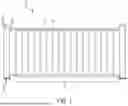
FIG. 1 is a side elevation view of a railing assembly in accordance with one embodiment of the present invention;
FIG. 2 is an exploded perspective view of a portion of a mounting bracket assembly of the railing assembly of FIG. 1;
FIG. 3 is a perspective view of a sub-bracket of the mounting bracket assembly of FIG. 2;
FIG. 4 is a perspective view of a mounting bracket of the mounting bracket assembly of FIG. 2;
FIG. 5 is an exploded partial perspective view of the mounting bracket assembly of FIG. 2;
FIG. 6 is a partial perspective view of the mounting bracket assembly of FIG. 2;
FIG. 7 is an exploded perspective view of a portion of a mounting bracket assembly in accordance with another embodiment of the present invention; and
FIG. 8 is an exploded perspective view of a portion of a mounting bracket assembly in accordance with another embodiment of the present invention.
DETAILED DESCRIPTION
The invention will now be described with reference to the drawing figures, in which like reference numerals refer to like parts throughout. For purposes of clarity in illustrating the characteristics of the present invention, proportional relationships of the elements have not necessarily been maintained in the drawing figures. It will be appreciated that any dimensions included in the drawing figures are simply provided as examples and dimensions other than those provided therein are also within the scope of the invention.
The following detailed description of the invention references specific embodiments in which the invention can be practiced. The embodiments are intended to describe aspects of the invention in sufficient detail to enable those skilled in the art to practice the invention. Other embodiments can be utilized and changes can be made without departing from the scope of the present invention. The present invention is defined by the appended claims and the description is, therefore, not to be taken in a limiting sense and shall not limit the scope of equivalents to which such claims are entitled.
As shown in FIG. 1, a railing assembly 10 may include rails 12 (e.g., top and bottom rails) with pickets or balusters 14 extending therebetween to form a section of railing 16. A railing section 16 may be connected to and supported by posts 18 at each end of the railing section 16 by coupling ends of rails 12 to rail mounts or brackets 20 mounted on the posts 18. The posts 18 may include a post sleeve 22 that slides over and covers a support structure or post body (not shown). A post sleeve 22 may be an extruded channel, tube, or sleeve, and may be made of aluminum or vinyl, for example. The interior of the post sleeve 22 may be smooth such that the post sleeve 22 can be slid over a post support structure having a corresponding size and shape as the interior of the post sleeve 22 with minimal resistance. Brackets 20 cannot typically be pre-installed on post sleeves 22 because screws fastening a bracket 20 to the post sleeve 22 would extend into the interior of the post sleeve 22 such that the post sleeve 22 cannot be slid over the post support structure.
As shown in FIG. 2, a raised feature or sub-bracket 24 may be attached to the post sleeve 22 (e.g., an exterior surface of the post sleeve 22) to aide in installation of the bracket 20 onto the post sleeve 22. The sub-bracket 24 may be installed or attached to the post sleeve 22 during manufacturing, for example, by using a glue, adhesive, or other suitable attachment means. The bracket 20 may be aligned with and temporarily mounted to the sub-bracket 24 during installation before the bracket 20 is screwed or fastened (or otherwise secured) to the post sleeve 22 and post support structure for final installation. Using screws or other fasteners that can penetrate the post sleeve 22 and fasten into the support structure can provide a more secure attachment of the bracket 20 to the post 18 and strengthen the overall railing assembly 10 compared to if the bracket 20 were only coupled to the post sleeve 22.
As shown in FIGS. 3-6, the bracket 20 may include a cavity or recess 26 in a rear surface 28 of the bracket 20. The recess 26 of the bracket 20 may receive the sub-bracket 24, or at least a portion thereof, when the bracket 20 is mounted to the post sleeve 22. The recess 26 may have a depth that approximately corresponds to the depth or raised-height of the sub-bracket 24 off of the post sleeve 22 such that the rear surface 28 of the bracket 20 may be mounted flush against the outer or exterior surface of the post sleeve 22 (in some embodiments, the depth or raised-height of the sub-bracket 24 may be less than the depth of the recess 26). The sub-bracket 24 may have a relatively low profile or raised-height off of the post sleeve 22 such that the post sleeve 22 may still be compactly and easily stored, stacked, and transported.
As shown in FIGS. 3-6, the sub-bracket 24 may have a size and shape that generally corresponds to the size and shape of the recess 26. As shown in the illustrated embodiment, the sub-bracket 24 and recess 26 each have a predominantly square or rectangular shape. However, it will be appreciated that the sub-bracket 24 and recess 26 may be of other shapes (e.g., circular, triangular, polygonal, any other suitable shape, etc.). The sub-bracket 24 may further include one or more of a notch, slot, or cutout 30 that receives at least one or more of a corresponding raised portion, stub, or protrusion 32, or at least portions thereof, formed in or projection from the recess 26. The protrusion 32 and cutout 30 combination can ensure proper orientation of the bracket 20 by preventing the bracket 20 from aligning or fitting over the sub-bracket 24 unless the protrusion 32 is properly oriented with the cutout 30 of the sub-bracket 24. While the protrusion 32 and cutout 30 are illustrated in the figures as each being generally U-shaped, it will be appreciated that they may be of other shapes (e.g., square, rectangular, circular, triangular, polygonal, any other suitable shape, etc.). Further yet, it will be appreciated that the bracket 20 and sub-bracket 24 may be located, angled, or otherwise positioned in manners other than illustrated in the figures. As shown, the protrusion 32 may include one of the screw holes 34 for fastening the bracket 20 to the post 18.
The size of the sub-bracket 24 may be approximately equal to the size of the recess 26 so that there is little slop, play, or tolerance between the bracket 20 and the sub-bracket 24 and to ensure that the bracket 20 is installed in the desired position an orientation on the post sleeve 22 (e.g., ensuring the bracket 20 is installed level). In some embodiments, the sub-bracket 24 and recess 26 may have an interference fit so that a bracket 20 is locked into position and resists falling off the sub-bracket 24, which can be useful for laying out components or temporary set up during installation prior to final assembly. The sub-bracket 24 may be made of a soft, deformable, or elastic material (e.g., rubber, silicone, soft plastic, etc.), which can promote the interference fit between the sub-bracket 24 and recess 26.
The sub-bracket 24 may be pre-installed on the post sleeve 22 in a desired position so that installers do not have to measure or otherwise locate the position for installing the bracket 20 on the post sleeve 22 in the field, which saves time. As shown in FIG. 2, a sub-bracket 24 may be installed at a height H1 from the bottom or base 36 of the post sleeve 22 corresponding to a position of a bottom rail 12, and a second sub-bracket 24 may be installed at a height H2 from the base of the post sleeve 22 corresponding to a position of a top rail 12. The sub-bracket 24 may be installed on a center of a face or surface of the post sleeve 22. For example, in the illustrated embodiment, the post sleeve 22 has a generally quadrilateral shape or extrusion with substantially planar faces 38 extending in a longitudinal direction and joined at the lateral edge to an adjacent substantially planar face 38b. The sub-bracket 24 may be centered laterally on a face 38 of the post sleeve 22 approximately equidistance from the adjacent faces 38b (i.e., centered along a width W of the face 38). In some embodiments, it may be desirable to have the rail 12 run flush with a front face of the post 18, in which case, the sub-bracket 24 can be installed off-center towards an outer edge of the post sleeve 22 such that the bracket 20 will be aligned along the outer edge of the post sleeve 22.
As shown in FIG. 7, some post sleeves 22 may have sub-brackets 24 installed on a first face 38a and an opposite face 38c that is parallel to the first face 38a (i.e., corresponding to a post 18 in the middle of two parallel railing sections 16). As shown in FIG. 8, some post sleeves may have sub-brackets 24 installed on a first face 38a and an adjacent face 38b that is perpendicular to the first face 38a (i.e., corresponding to a corner post 18). In other embodiments, a post sleeve 22 may include sub-brackets 24 on three or four faces (i.e., corresponding to a T-junction post 18 or a four-way junction post 18, respectively). In other embodiments, the post sleeve 22 may be extruded to form a round or other non-quadrilateral shape, and the sub-brackets 24 may be positioned around surface or faces of the post sleeve 22 as needed for the desired configuration of the railing assembly 10.
Various embodiments of systems, devices, and methods have been described herein. These embodiments are given only by way of example and are not intended to limit the scope of the invention. It should be appreciated, moreover, that the various features of the embodiments that have been described may be combined in various ways to produce numerous additional embodiments. Moreover, while various materials, dimensions, shapes, configurations, locations, etc. have been described for use with disclosed embodiments, others besides those disclosed may be utilized without exceeding the scope of the invention.
Persons of ordinary skill in the relevant arts will recognize that the subject matter hereof may comprise fewer features than illustrated in any of the individual embodiments described above. The embodiments described herein are not meant to be an exhaustive presentation of how the various features of the subject matter herein may be combined. Accordingly, the embodiments are not mutually exclusive combinations of features; rather, the various embodiments can comprise a combination of different individual features selected from different individual embodiments, as understood by persons of ordinary skill in the art. Moreover, elements described with respect to one embodiment can be implemented in other embodiments even when not described in such embodiments unless otherwise noted.
The numerical ranges in this disclosure are approximate, and thus may include values outside of the range unless otherwise indicated. Numerical ranges include all values from and including the lower and the upper values, in increments of one unit, provided that there is a separation of at least two units between any lower value and any higher value. These are only examples of what is specifically intended, and all possible combinations of numerical values between the lowest value and the highest value enumerated, are to be considered to be expressly stated in this disclosure.
As used herein, “a,” “an,” or “the” can mean one or more than one. For example, “an” image can mean a single image or a plurality of images.
The term “and/or” as used in a phrase such as “A and/or B” herein can include both A and B; A or B; A (alone); and B (alone). Likewise, the term “and/or” as used in a phrase such as “A, B, and/or C” can include at least the following embodiments: A, B, and C; A, B, or C; A or C; A or B; B or C; A and C; A and B; B and C; A (alone); B (alone); and C (alone).
As used herein, the term “about” when referring to a measurable value such as an amount, a temporal duration, and the like, can include variations of +/−20%, more preferably +/−10%, even more preferably +/−5% from the specified value, as such variations are appropriate to reproduce the disclosed methods and systems.
From the foregoing, it will be seen that this invention is one well adapted to attain all the ends and objects hereinabove set forth together with other advantages which are inherent to the structure and method. It will be understood that certain features and sub combinations are of utility and may be employed without reference to other features and sub combinations. This is contemplated by and is within the scope of the claims. Since many possible embodiments of the invention may be made without departing from the scope thereof, it is also to be understood that all matters herein set forth or shown in the accompanying drawings are to be interpreted as illustrative and not limiting.
The constructions described above and illustrated in the drawings are presented by way of example only and are not intended to limit the concepts and principles of the present invention. Thus, there has been shown and described several embodiments of a novel invention. As is evident from the foregoing description, certain aspects of the present invention are not limited by the particular details of the examples illustrated herein, and it is therefore contemplated that other modifications and applications, or equivalents thereof, will occur to those skilled in the art. The terms “having” and “including” and similar terms as used in the foregoing specification are used in the sense of “optional” or “may include” and not as “required”. Many changes, modifications, variations and other uses and applications of the present construction will, however, become apparent to those skilled in the art after considering the specification and the accompanying drawings. All such changes, modifications, variations and other uses and applications which do not depart from the spirit and scope of the invention are deemed to be covered by the invention which is limited only by the claims which follow.
Claims
What is claimed is:1. A railing assembly comprising:
a post sleeve having an interior configured to at least partially receive a structural support post;
a sub-bracket attached to an exterior surface of the post sleeve;
a mounting bracket having a recessed portion defined in a rear of the mounting bracket; and
a rail couplable to the mounting bracket to be at least partially supported by the mounting bracket;
wherein, when assembled, the sub-bracket is positioned at least partially within the recessed portion of the mounting bracket.
2. The railing assembly of claim 1, wherein, when assembled, a rear surface of the mounting bracket abuts the exterior surface of the post sleeve.
3. The railing assembly of claim 1, wherein the sub-bracket forms an interference fit with the recessed portion of the mounting bracket.
4. The railing assembly of claim 1, wherein the sub-bracket comprises an elastic or deformable material.
5. The railing assembly of claim 1, wherein the sub-bracket is attached to the exterior surface of the post sleeve by an adhesive.
6. The railing assembly of claim 1, wherein the recessed portion of the mounting bracket includes a protrusion extending therein and the sub-bracket includes a cutout defined therein for receiving the protrusion.
7. The railing assembly of claim 1, wherein the post sleeve includes a substantially planar first face, a substantially planar second face oriented generally perpendicular to the first face, and a substantially planar third face oriented generally parallel to the first face.
8. The railing assembly of claim 7, wherein a first sub-bracket is attached to an exterior surface of the first face at a first height and a second sub-bracket is attached to the exterior surface of the first face at a second height.
9. The railing assembly of claim 8, wherein the first sub-bracket and the second sub-bracket are each centered along a width of the first face.
10. The railing assembly of claim 7, wherein a first sub-bracket is attached to an exterior surface of the first face and a second sub-bracket is attached to an exterior surface of the second face.
11. A post sleeve for a railing assembly, the post sleeve comprising:
an extruded channel, an interior of the extruded channel configured to receive a structural support post; and
a sub-bracket attached to an exterior surface of the extruded channel, the sub-bracket configured to receive a mounting bracket that is configured to mount onto the post sleeve and couple a rail to the post sleeve, the sub-bracket having a size and shape that generally corresponds to a recessed portion of the mounting bracket.
12. The post sleeve of claim 11, wherein the sub-bracket includes a cutout configured to receive a protrusion of the recessed portion of the mounting bracket.
13. The post sleeve of claim 11, wherein the sub-bracket is configured to form an interference fit with the recessed portion of the mounting bracket.
14. The post sleeve of claim 11, wherein the sub-bracket is attached to the exterior surface of the post sleeve by an adhesive.
15. The post sleeve of claim 11, wherein the post sleeve includes a substantially planar first face, a substantially planar second face oriented perpendicular to the first face, and a substantially planar third face oriented parallel to the first face, wherein a first sub-bracket is attached to an exterior surface of the first face and a second sub-bracket is attached to an exterior surface of the second face.
16. The post sleeve of claim 11, wherein a first sub-bracket is attached to the exterior surface at a first height and a second sub-bracket is attached to the exterior surface at a second height.
17. A bracket assembly comprising:
a bracket for coupling to a rail, the bracket including a recessed portion defined in a rear of the bracket, the bracket including a screw hole for a fastener to extend therethrough to mount the bracket to a support structure; and
a sub-bracket corresponding to the recessed portion of the bracket, the sub-bracket configured to attach to the support structure;
wherein positioning the sub-bracket in the recessed portion locks the bracket into a fixed position relative to the sub-bracket.
18. The bracket assembly of claim 17, wherein positioning the sub-bracket in the recessed portion forms an interference fit between the sub-bracket and the recessed portion of the mounting bracket.
19. The bracket assembly of claim 17, wherein the sub-bracket comprises an elastic or deformable material.
20. The bracket assembly of claim 17, wherein the recessed portion of the mounting bracket includes a protrusion and the sub-bracket includes a cutout for receiving the protrusion.
Images & Drawings included:


Sources:
- United States Patent and Trademark Office - verify current appl. status at the USPTO↗
Similar patent applications:
Recent applications in this class:
- » 20260125910 2026-05-07
RAILING ASSEMBLY HAVING BALUSTERS WITH LOCKING TABS - » 20260085524 2026-03-26
BRACKET, RAILING SYSTEM INCLUDING THE SAME, AND METHOD OF ASSEMBLING A RAILING SYSTEM - » 20260043247 2026-02-12
SPLIT VERTICAL RAILING - » 20260043246 2026-02-12
PIVOT-LOAD VERTICAL RAILING - » 20260043245 2026-02-12
TOP-LOAD VERTICAL RAILING - » 20260043244 2026-02-12
VERTICAL RAILING - » 20260043243 2026-02-12
TOW HITCH FOR VERTICAL RAILING - » 20260043242 2026-02-12
TOP-LOAD VERTICAL RAILING - » 20260043241 2026-02-12
SIDE-LOAD VERTICAL RAILING - » 20260009232 2026-01-08
BALUSTER CONNECTORS AND SYSTEMS HAVING THE SAME