TENSIONED WELLHEAD SYSTEMS AND RELATED METHODS
US20260125962A1
2026-05-07
19/376,532
2025-10-31
Smart Summary: A wellhead system has a central part called a receptacle. A housing is placed inside this receptacle along its central line. There are special connections, called shouldered engagements, that hold the housing tightly in place. These connections help keep the housing under tension, ensuring it stays secure. This design improves the stability and performance of the wellhead system. 🚀 TL;DR
Abstract:
An embodiment of a wellhead system includes a receptacle having a central axis. In addition, the wellhead system includes a wellhead housing that is axially inserted into the receptacle relative to the central axis. Further, the wellhead system includes a pair of shouldered engagements coupled between the receptacle and the wellhead housing that are configured to maintain tension in the wellhead housing axially between the pair of shouldered engagements relative to the central axis.
Applicant:
Interested in similar patents?
Get notified when new applications in this technology area are published.
Classification:
E21B33/038 » CPC main
Sealing or packing boreholes or wells; Surface sealing or packing; Well heads; Setting-up thereof specially adapted for underwater installations Connectors used on well heads, e.g. for connecting blow-out preventer and riser
E21B33/037 » CPC further
Sealing or packing boreholes or wells; Surface sealing or packing; Well heads; Setting-up thereof specially adapted for underwater installations Protective housings therefor
Description
CROSS-REFERENCE TO RELATED APPLICATIONS
This application claims priority to and the benefit of U.S. Provisional Ser. No. 63/715,342, filed Nov. 1, 2024, and entitled “Method of Rigidizing Wellhead Housing to Receptacle,” which is incorporated by reference herein in its entirety.
BACKGROUND
Embodiments disclosed herein are generally directed to wellhead systems for a subterranean wellbore, such as subsea wellhead systems for an offshore subterranean wellbore.
A wellbore may be formed in a subterranean formation to access resources, such as hydrocarbons, water, or other minerals. Some wellbores may be located in an offshore location, so that drilling, production, and maintenance operations for such a wellbore involves traversing through a subsea environment. Such offshore wellbores may include a wellhead system (or “subsea wellhead system”) that is located on the sea floor and that serves as an interface between surface equipment and the wellbore.
SUMMARY
Some embodiments disclosed herein are directed to a wellhead system that includes a receptacle having a central axis. In addition, the wellhead system includes a wellhead housing that is axially inserted into the receptacle relative to the central axis. Further, the wellhead system includes a pair of shouldered engagements coupled between the receptacle and the wellhead housing that are configured to maintain tension in the wellhead housing axially between the pair of shouldered engagements relative to the central axis.
Some embodiments disclosed herein are directed to a wellhead system that includes a receptacle. The receptacle includes a central axis, an upper end, a lower end axially spaced from the upper end along the central axis, and an inner landing shoulder defined in the receptacle, between the upper end and the lower end. In addition, the wellhead system includes a wellhead housing. The wellhead housing includes an outer landing shoulder. The wellhead housing is axially inserted into the receptacle so that the outer landing shoulder is engaged with the inner landing shoulder of the receptacle. Further, the wellhead system includes a locking assembly engaged between an outer surface of the wellhead housing and the receptacle such that a portion of the wellhead housing extending axially between the outer landing shoulder and the lower end of the receptacle is axially tensioned relative to the central axis.
Some embodiments disclosed herein are directed to a method including (a) inserting a wellhead housing into a receptacle of a wellhead system. In addition, the method includes (b) engaging an outer landing shoulder on the wellhead housing with an inner landing shoulder of the receptacle. Further, the method includes (c) tensioning the wellhead housing below the outer landing shoulder after (b). Still further, the method includes (d) maintaining a tension of the wellhead with a locking assembly.
BRIEF DESCRIPTION OF DRAWINGS
For a detailed description of various exemplary embodiments, reference will now be made to the accompanying drawings in which:
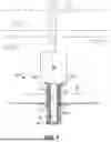
FIG. 1 is a schematic diagram of a subsea wellhead system according to some embodiments disclosed herein;
FIGS. 2A-2C are sequential, enlarged cross-sectional views of an engagement between a wellhead assembly and receptacle of the subsea wellhead system of FIG. 1 according to some embodiments disclosed herein;
FIGS. 3A-3D are sequential, enlarged cross-sectional views of an engagement between a wellhead assembly and receptacle of the subsea wellhead system of FIG. 1 according to some embodiments disclosed herein;
FIGS. 4A-4C are sequential, enlarged cross-sectional views of an engagement between a wellhead assembly and receptacle of the subsea wellhead system of FIG. 1 according to some embodiments disclosed herein;
FIGS. 5A-5C are sequential, enlarged cross-sectional views of an engagement between a wellhead assembly and receptacle of the subsea wellhead system of FIG. 1 according to some embodiments disclosed herein;
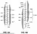
FIGS. 6A and 6B are enlarged views of a locking assembly including the engagement illustrated in FIGS. 5A-5C according to some embodiments disclosed herein; and
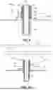
FIGS. 7-10 are schematic sequential views of a method of constructing and installing a wellhead system according to some embodiments disclosed herein.
DETAILED DESCRIPTION
A subsea wellhead system may provide an interface between surface equipment located on or above the sea floor and a subterranean wellbore. Specifically, the wellhead system may support various surface equipment such as a blowout preventer (BOP) stack, valve tree, riser pipe connection, or combinations thereof. In addition, the wellhead system may also be coupled to (or may include) one or more casing pipes or other conductors that are inserted into the seabed and/or wellbore. During drilling or production operations, the wellhead system may be subjected to cyclic loads. Specifically, a riser pipe may extend between a surface vessel (such as an offshore platform, drill ship, floating production storage and offloading system (FPSO), etc.). The movement of the surface vessel on the sea surface may transfer bending moments and/or axial loads to the wellhead system. In addition, pressure fluctuations in the wellbore may also impart loads on the wellhead system during operations. These cyclic loads may cause fatigue failures in one or more connections of the wellhead system. For example, the wellhead system may include a wellhead housing that is landed in a receptacle coupled to a foundation on the sea floor. The engagement between the wellhead housing and receptacle may be subjected to the aforementioned cyclic loads so that this connection may be prone to fatigue failure.
Thus, some connections in a subsea wellhead may be subjected to pre-loading to resist fatigue wear. Such pre-loading may involve placing heavy top loads on the wellhead system in the subsea environment, often by use of the heavy surface components mounted thereto. Wellsite operators would prefer to conduct fewer operations in the subsea environment given the harsh and remote environment at the sea floor. As a result, a system that allows a wellhead system to be pre-loaded onshore before deployment into the subsea environment would be desirable. However, application of the heavy top loads to provide such pre-loading in existing systems is often not practical in an onshore facility.
Accordingly, embodiments disclosed herein include wellhead systems that are configured to be pre-loaded for fatigue resistance without necessitating a heavy top load in the subsea environment. In some embodiments, the wellhead systems may be configured to pre-load a connection, such as a connection between a wellhead housing and receptacle of the wellhead system, by tensioning the wellhead housing below the shouldered engagement within the receptacle. Tensioning the wellhead housing in this manner may be accomplished by use of equipment and systems that may be readily deployed in an onshore facility. As a result, the wellhead systems of at least some of the embodiments disclosed herein may be pre-loaded onshore, before deployment into the subsea environment, which may improve efficiency and reduce the costs associated with a wellsite construction operation.
Referring now to FIG. 1, a subsea wellhead system 10 that is configured to be pre-loaded against fatigue wear is shown according to some embodiments disclosed herein. The subsea wellhead system 10 (“wellhead system 10”) includes a foundation 20, a receptacle 30 coupled to the foundation 20, and a wellhead housing 40 landed within and coupled to the receptacle 30.
The foundation 20 may comprise a support structure that is landed on the sea floor 5. The foundation 20 may include or be coupled to one or more mud mats, anchors, or other components (not shown) that are configured to secure and position the foundation 20 on the sea floor 5.
The receptacle 30 may comprise a tubular housing or member that is coupled to and supported on the foundation 20. The receptacle 30 may include a central or longitudinal axis 35 (“axis 35”), a first or upper end 30a, and a second or lower end 30b that is axially spaced from the upper end 30a along axis 35 relative to axis 35. In some embodiments, the axis 35 may be coaxially aligned with a central axis or centerline of a subsea wellbore (not shown) extending into the sea floor 5. In some embodiments, the receptacle 30 may include or be coupled to a casing pipe or other conductor (not shown) that is extended into the sea floor 5 to form a conductor, liner, or casing of the wellbore (not shown).
The wellhead housing 40 may be a tubular member that is inserted axially through the receptacle 30 to be substantially coaxially aligned along the axis 35. The wellhead housing 40 may be configured to at least partially support one or more surface components 26 above the sea floor 5. Specifically, the wellhead housing 40 includes a first or upper end 40a that is coupled to the surface component(s) 26. In addition, the wellhead housing 40 includes a second or lower end 40b that is axially spaced from the upper end 40a along axis 35. The lower end 45b may be inserted into the sea floor 5 so that the wellhead housing 40 may define one or more casing, liners, or other conductors of the wellbore (not shown) according to some embodiments. The wellhead housing 40 may include a throughbore 42 that may provide access for one or more components and/or fluids into and out of the wellbore during operations. For instance, in some embodiments, a casing hanger may be landed within the wellhead housing 40 that is configured to support a casing pipe for the wellbore.
In some embodiments, the surface equipment 26 may include BOP stack, valve tree (such as a so-called Christmas valve tree), etc. The particular components included within the surface equipment 26 may be selected based on the stage of life for the wellbore, such as drilling, completion, production, workover, etc.
However, in at least some embodiments, the surface equipment 26 may include a connection for a riser pipe 8 that may extend upward through the subsea environment 7 to a surface vessel 9 positioned at the sea surface 6. In some embodiments, the surface vessel 9 may be a floating vessel, such as an FPSO, drill ship, spar platform, tension leg platform (TLP), semi-submersible platform, etc. The movement of such a surface vessel 9 at the sea surface 6 may induce cyclic loads (such as bending moments, axial loads) onto the wellhead system 10 via the riser pipe 8 and surface equipment 26. In addition, pressure fluctuations within the wellbore (not shown) may also induce cyclic loads on the wellhead system 10. These cyclic loads may be transferred to the connection between the receptacle 30 and the wellhead housing 40, which may ultimately lead to fatigue wear and failure of this connection. Thus, as will be described in more detail herein, the connection between the wellhead housing 40 and receptacle 30 may be pre-loaded to increase a resistance of this connection to fatigue wear.
Embodiments of the connection between the wellhead housing 40 and receptacle 30 are described herein. As will be described in more detail, at least some of these embodiments may induce a tension on the wellhead housing 40 below the engaged landing shoulders of the wellhead housing 40 and receptacle 30 to pre-load this shouldered engagement. Without being limited to this or any other theory, tensioning the wellhead housing 40 below the shouldered engagement with the receptacle 30 may avoid the use of a heavy top load on the upper end 40a of the wellhead housing 40. As a result, in at least some embodiments, pre-loading may be conducted onshore, before the wellhead system 10 is installed on the sea floor 5, so that the construction operation for the wellhead system 10 may be more efficient. However, it should be appreciated that, for at least some embodiments disclosed herein, the pre-loading of the connection between the wellhead housing 40 and receptacle 30 may still be conducted after the wellhead system 10 is installed on the sea floor 5.
Various example engagements between the wellhead housing 40 and receptacle 30 are now described with reference to FIGS. 2-5. These drawings schematically depict the wellhead housing 40 in a shortened configuration and illustrate a partial section view of the wellhead housing 40 and receptacle 30 to simplify the drawings.
Referring now to FIGS. 2A-2C, the engagement between the wellhead housing 40 and receptacle 30 of the wellhead system 10 (FIG. 1) is shown according to some embodiments. Referring specifically to FIG. 2A, the wellhead housing 40 may include a radially outer surface 40c and a radially inner surface 40d that both generally extend axially between the ends 40a, 40b relative to axis 35 (such as when the wellhead housing 40 is inserted into the receptacle 30 as shown). Similarly, the receptacle 30 may include a radially outer surface 30c and a radially inner surface 30d that both generally extend axially between the ends 30a, 30b relative to axis 35. The radially inner surface 40d may define the throughbore 42 of the wellhead housing 40. Likewise, the radially inner surface 30d of the receptacle 30 may define a throughbore 32 that is configured to receive the wellhead housing 40 during operations.
The radially outer surface 40c of the wellhead housing 40 includes a radially outer landing shoulder 54, and the radially inner surface 30d includes a radially inner landing shoulder 52. The radially outer landing shoulder 54 and the radially inner landing shoulder 52 may comprise a frustoconical shoulders that are oriented at a non-zero (such as acute) angle relative to the central axis 35. The radially outer landing shoulder 54 may be an axially downward facing frustoconical surface that generally faces toward the lower end 40b of the wellhead housing 40, and the radially inner landing shoulder 52 may be an axially upward facing frustoconical surface that generally faces toward the upper end 30a of the receptacle 30.
When the wellhead housing 40 is axially inserted into the receptacle 30 (such as the throughbore 32) along the axis 35, the radially outer landing shoulder 54 may be engaged or landed on the radially inner landing shoulder 52 to define a first shouldered engagement 50 between the wellhead housing 40 and receptacle 30. The orientation of the landing shoulders 52, 54 may match or at least correspond to one another so that engagement of the radially outer landing shoulder 54 on the radially inner landing shoulder 52 may be configured to coaxially center (or substantially center) the wellhead housing 40 within the receptacle 30 along the axis 35.
In addition, each of the wellhead housing 40 and receptacle 30 may have additional recesses 64 and 66 that are positioned axially below the first shouldered engagement 50 relative to axis 35. Specifically, the recesses 64, 66 may be axially positioned between the first shouldered engagement 50 and the lower end 30b of the receptacle 30 along the axis 35.
The recess 64 may be defined on the radially outer surface 40c of the wellhead housing 40, and the recess 66 may be defined on the radially inner surface 30d of the receptacle 30. Specifically, the recess 64 may comprise a radially extending recess that extends radially inward and into the radially outer surface 40c, and the recess 66 is a radially extending recess that extends radially outward and into the radially inner surface 30d. The recesses 64, 66 may comprise grooves that are formed in the surfaces 40c, 30d, respectively, that extend circumferentially about the axis 35.
As a will be described in more detail below, after the wellhead housing 40 is inserted into the receptacle 30 to establish the first shouldered engagement 50, the wellhead housing 40 may be tensioned axially below the first shouldered engagement 50 relative to axis 35. This tension in the wellhead housing 40 may be configured to pre-load the first shouldered engagement 50 to increase a fatigue resistance for this connection as previously described.
The sequence from FIGS. 2A-2C illustrates an operation for applying and maintaining the tension in the wellhead housing 40 according to some embodiments. The recesses 64, 66 may at least partially define a locking assembly 60 that is configured to maintain the tension in the wellhead housing 40. Before tension is applied to the wellhead housing 40, the recesses 64, 66 may be at least partially misaligned along axis 35. Specifically, the recess 64 defined on the radially outer surface 40c may initially be axially positioned between the recess 66 and the first shouldered engagement 50 relative to axis 35. Thus, in the initial un-tensioned state of the wellhead housing 40 shown in FIG. 2A, the recess 64 may be radially opposed (at least partially) by the radially inner surface 30c of the receptacle 30.
The locking assembly 60 may also include (or be at least partially defined by) a snap ring 62 that is initially inserted into the recess 64 of the wellhead housing 40. The snap ring 62 may be a biased or spring-loaded member that is biased radially outward (or away) from the axis 35. Initially, the snap ring 62 may be radially compressed and maintained in the recess 64 by the radially inner surface 30d and the un-tensioned wellhead housing 40 as shown in FIG. 2A.
As shown in the sequence from FIG. 2A to 2B, axial tension (relative to axis 35) may be applied to the wellhead housing 40 such that the wellhead housing 40 is axially extended (or stretched), such as via elastic deformation, to axially align the recess 64 on the wellhead housing 40 with the recess 66 on the receptacle 30 relative to axis 35. Once the recesses 64, 66 are axially aligned, the snap ring 62 may radially expand (such as via its own bias) to engage within both of the recesses 64, 66. Once the snap ring 62 is radially expanded into the recesses 64, 66 as shown in FIG. 2B, the engagement between the snap ring 62 and surfaces of the recesses 64, 66 may define a second shouldered engagement 68 that is axially positioned between the first shouldered engagement 50 and the lower end 30b of the receptacle 30 relative to axis 35.
The second shouldered engagement 68 may be configured to maintain the tension in the wellhead housing 40 and thus the pre-load on the first shouldered engagement 50. Thus, upon the establishment of the second shouldered engagement 68, the wellhead housing 40 may have a tensioned portion 44 that extends axially between the shouldered engagements 50, 68 relative to axis 35. In addition, the shouldered engagements 50, 68 may also place a portion 34 of the receptacle 30 in compression along the axis 35. The portion 34 (“compressed portion 34”) likewise also extends axially between the shouldered engagements 50, 68 relative to axis 35.
Any suitable system or method may be used to apply tension to the wellhead housing 40 according to various embodiments. For instance, as shown in FIGS. 2A-2C, in some embodiments, one or more linear actuators 70 may be configured to bear against the lower end 30b of the receptacle 30 and the wellhead housing 40 to tension the wellhead housing 40 and establish the second shouldered engagement 68 as previously described. In particular, the linear actuator(s) 70 may comprise one or more hydraulic cylinders, linear motors, pneumatic actuators, or other suitable linear actuators. The linear actuator(s) 70 may be supported on a reaction plate 80 that is coupled to or defined on the radially outer surface 40c of the wellhead housing 40. In some embodiments, the linear actuator(s) 70 may be supported or engaged with a shoulder that is integrally defined on the wellhead housing 40 or another suitable structure that is configured to transfer an axially directed force from the wellhead actuator(s) 70 to the wellhead housing 40 relative to axis 35 during operations. In some embodiments, a plurality of linear actuators 70 may be circumferentially distributed about the wellhead housing 40 relative to axis 35.
As shown in the sequence from FIGS. 2A to 2B, the linear actuator(s) 70 may be extended to axially bear against the lower end 30b of receptacle 30 and the reaction plate 80 relative to axis 35 and therefore to tension the wellhead housing 40. As shown in the sequence from FIGS. 2B to 2C, once the second shouldered engagement 68 is established via radial expansion of the snap ring 62 into the recesses 64, 66 as previously described, the linear actuators 70 may be retracted and removed. In some embodiments, the reaction plate 80 may also be removed from the wellhead housing 40 (if a reaction plate 80 is used as previously described).
The tensioning operations illustrated in FIGS. 2A-2C may be performed in an onshore facility, such as a shipyard, manufacturing plant, etc. Thus, the linear actuator(s) 70 and reaction plate 80 (if used) may be maintained at the onshore facility and may not be transported to the offshore wellsite or the subsea environment 7. In some embodiments, the tensioning operations illustrated in FIGS. 2A-2C may be performed in the subsea environment 7, such as after the wellhead system 10 is installed (or partially installed) on the sea floor 5. Thus, in some embodiments, the linear actuator(s) 70 may be configured to be actuated remotely, such as with an remotely operated vehicle (ROV), and may be configured to be maintained on the wellhead system 10 in the subsea environment 5 after tension is applied and maintained (by the locking assembly 60) in the wellhead housing 40 as previously described.
Referring now to FIGS. 3A-3D, the engagement between the wellhead housing 40 and receptacle 30 of the wellhead system 10 (FIG. 1) is shown according to some embodiments. The engagement between the wellhead housing 40 and receptacle 30 illustrated in FIGS. 3A-3D may be substantially similar to that illustrated in FIGS. 2A-2C, and thus, the features of the embodiment of the engagement shown in FIGS. 3A-3D that are shared with the embodiment illustrated in FIGS. 2A-2C are identified with the same reference numerals and the description herein will focus on the features of the engagement shown in FIGS. 3A-3D that are different from that shown in FIGS. 2A-2C.
Specifically, as shown in FIGS. 3A-3D, in some embodiments, the locking assembly 60 may be replaced with a locking assembly 160. The locking assembly 160 may include (or be defined by) a threaded ring 164 that is threadably engaged with the radially outer surface 40c of the wellhead housing 40. In addition, the locking assembly 160 may include a recess 166 that extends radially into the radially inner surface 30d and axially away into the lower end 30b relative to axis 35. The recess 166 may thus define a radially extending shoulder 162 on that receptacle 30 that is proximate to the lower end 30b (such as more proximate the lower end 30b than the upper end 30a along the axis 35).
As shown in the sequence from FIGS. 3A to 3B, when tension is applied to the wellhead housing 40, the locking ring 164 may be axially spaced from away from the shoulder 162 relative to axis 35. The wellhead housing 40 may be tensioned via any of the methods or systems previously described (such as linear actuator(s) 70 and reaction plate 80). As shown in the sequence from FIGS. 3B to 3C, after tension is applied to the wellhead housing 40, the locking ring 164 may be threadably advanced along the radially outer surface 40c to engage with the shoulder 162. In some embodiments, the locking ring 164 may be torqued against the shoulder 162 or may simply be snugged against the shoulder 162. In some embodiments, a tool (such as a spanner wrench) may be used to threadably advance the locking ring 164 along the radially outer surface 40c of the wellhead housing 40.
As shown in the sequence from FIGS. 3C to 3D, after the locking ring 164 is engaged with the shoulder 162, the linear actuator(s) 70 (or other tension applying system or device(s)) may be removed to allow the axial elastic return of the wellhead housing 40 to compress the locking ring 164 against the shoulder 162. The engagement between the locking ring 164 and shoulder 162 may define a second shouldered engagement 168 that is axially positioned between the first shouldered engagement 50 and the lower end 30b of the receptacle 30 relative to axis 35.
As was previously described for the second shouldered engagement 68 (FIGS. 2A-2C), the second shouldered engagement 168 may be configured to maintain the tension in the wellhead housing 40 and thus the pre-load on the first shouldered engagement 50. Thus, the establishment of the second shouldered engagement 168 may form the tensioned portion 44 in the wellhead housing 40 that extends axially between the shouldered engagements 50, 168 relative to axis 35. In addition, the shouldered engagements 50, 168 may also form the compressed portion 34 of the receptacle 30 along the axis 35, between the shouldered engagements 50, 168.
Referring now to FIGS. 4A-4C, the engagement between the wellhead housing 40 and receptacle 30 of the wellhead system 10 (FIG. 1) is shown according to some embodiments. The engagement between the wellhead housing 40 and receptacle 30 illustrated in FIGS. 4A-4C may be substantially similar to that illustrated in FIGS. 2A-2C, and thus, the features of the embodiment of the engagement shown in FIGS. 4A-4C that are shared with the embodiment illustrated in FIGS. 2A-2C are identified with the same reference numerals and the description herein will focus on the features of the engagement shown in FIGS. 4A-4C that are different from that shown in FIGS. 2A-2C.
Specifically, as shown in FIGS. 4A-4C, in some embodiments, the locking assembly 60 may be replaced with a locking assembly 260. The locking assembly 260 may include (or be defined by) one or more locking dogs 262 that may be radially advanced into a recess 264 defined on the wellhead housing 40 to maintain a tension thereon.
As shown in FIG. 4A, each (or the) locking dog 262 may be initially positioned in a corresponding recess 266 that extends radially into the radially inner surface 30d of the receptacle 30. The one or more recesses 264 may extend radially into the radially outer surface 40c of the wellhead housing 40. Generally speaking, the recess(es) 264 may be circumferentially aligned with the recess(es) 266, but before tension is applied to the wellhead housing 40, the recess(es) 264 may be at least partially misaligned with the recess(es) 266.
In some embodiments, the receptacle 30 includes a plurality of recesses 266 that are circumferentially distributed about the central axis 35, and the wellhead housing 40 may include a plurality of recesses 264 that are circumferentially distributed about the axis 35. Each of the recesses 266 may include a corresponding locking dog 262 positioned therein as previously described. Each of the recesses 264 may be circumferentially aligned with a corresponding one of the recesses 266. However, each of the recesses 264 may be at least partially misaligned along axis 35 with the corresponding recess 266 as previously described.
As shown in the sequence from FIGS. 4A to 4B, when tension is applied to the wellhead housing 40, recess(es) 264 may be axially aligned with the corresponding recess(es) 266 relative to axis 35. The wellhead housing 40 may be tensioned via any of the methods (such as linear actuator(s) 70 and reaction plate 80) as previously described. As shown in the sequence from FIGS. 4B to 4C, after tension is applied to the wellhead housing 40, the locking dog(s) 262 may be partially advanced radially out of the recess(es) 266 and into the corresponding recess(es) 264 to be engage within each of the corresponding pair of recesses 264, 266. In some embodiments, the locking dog(s) 262 may each be radially expanded into the recess(es) 264 via an actuator 267. In some embodiments, the actuator 267 may comprise a threaded actuator (such as a threaded rod, stud, bolt, etc.) that is threadably engaged in a threaded port 269 that extends radially from the recess 266 to the radially outer surface 30c of receptacle 30. During operations, the threaded actuator 267 may be threadably advanced into the port 269 to engage with and displace the locking dog 262 partially out of the recess 266 and into the recess 264.
In some embodiments, the actuator 267 may comprise a linear actuator that is configured to be selectively extended to displace the locking dog 262 partially out of the recess 266 and into the recess 264 as previously described. The linear actuator may comprise a hydraulic or pneumatic piston according to some embodiments. However, other types of linear actuators are contemplated. In some embodiments, the locking dog(s) 262 may be actuated into the recesses 264, 266 via fluid pressure that may be selectively communicated to the recess(es) 266. Still other methods of actuating the locking dog(s) 262 (such as via actuation rings, or other systems) are contemplated herein.
After the locking dog(s) 262 is (or are) engaged within the corresponding recesses 264, 266, the linear actuator(s) 70 (or other tension applying system or device(s)) may be removed so that the locking dog(s) 262 may maintain the tension in the wellhead housing 40. As annotated in FIG. 4C, the engagement between the locking dog(s) 262 and corresponding recesses 264, 266 may define a second shouldered engagement 268 that is axially positioned between the first shouldered engagement 50 and the lower end 30b of the receptacle 30 relative to axis 35.
As was previously described for the second shouldered engagement 68 (FIGS. 2A-2C), the second shouldered engagement 268 may be configured to maintain the tension in the wellhead housing 40 and thus the pre-load on the first shouldered engagement 50. Thus, the establishment of the second shouldered engagement 268 may form the tensioned portion 44 in the wellhead housing 40 that extends axially between the shouldered engagements 50, 268 relative to axis 35. In addition, the shouldered engagements 50, 268 may also form the compressed portion 34 of the receptacle 30 along the axis 35, between the shouldered engagements 50, 268.
Referring now to FIGS. 5A-5C, the engagement between the wellhead housing 40 and receptacle 30 of the wellhead system 10 (FIG. 1) is shown according to some embodiments. The engagement between the wellhead housing 40 and receptacle 30 illustrated in FIGS. 5A-5C may be substantially similar to that illustrated in FIGS. 2A-2C, and thus, the features of the embodiment of the engagement shown in FIGS. 5A-5C that are shared with the embodiment illustrated in FIGS. 2A-2C are identified with the same reference numerals and the description herein will focus on the features of the engagement shown in FIGS. 5A-5C that are different from that shown in FIGS. 2A-2C.
Specifically, as shown in FIGS. 5A-5C, in some embodiments, the locking assembly 60 may be replaced with a locking assembly 360. The locking assembly 360 may include a pair of ratchet assemblies 362, 364 coupled to or defined on the wellhead housing 40 and receptacle 30 that are configured to maintain a tension on the wellhead housing 40 during operations.
As shown in FIG. 5A, the pair of ratcheting assemblies 362, 364 includes a first ratchet assembly 362 that is coupled to or defined on the radially outer surface 40c of the wellhead housing 40, axially below the radially outer landing shoulder 54 relative to axis 35, and a second ratchet assembly 364 that is coupled to or defined on the radially inner surface 30d of the receptacle 30 axially below the radially inner landing shoulder 52 relative to axis 35.
As shown in FIGS. 6A and 6B, the first ratchet assembly 362 includes a plurality of ratchet teeth 361 that are axially adjacent to one another relative to axis 35. Similarly, the second ratchet assembly 364 includes a plurality of ratchet teeth 366 that are axially adjacent to one another relative to axis 35. Initially, as shown in FIGS. 5A and 6A, the teeth 361, 366 of the ratchet assemblies 362, 364, respectively, may be at least partially meshed or engaged with one another before tension is applied to the wellhead housing 40. Thereafter, as seen in FIGS. 5B and 6B, when tension is applied to the wellhead housing 40, the teeth 361 of first ratchet assembly 362 may be slid past or over the teeth 366 of the second ratchet assembly 364. The wellhead housing 40 may be tensioned via any of the methods (such as linear actuator(s) 70 and reaction plate 80) as previously described.
The teeth 361, 366 of the ratchet assemblies 362, 364, respectively, may extend circumferentially (such as partially or fully) about the surfaces 40c, 30d, respectively, relatively to axis 35. In some embodiments, one or both of the ratchet assemblies 362, 364 may include multiple axial rows of teeth 361, 366, respectively, and one or more of these rows of teeth 361, 366 may comprise a continuous circumferential tooth 361, 366, a plurality of circumferential tooth sections that are circumferentially distributed about the axis 35, or some combination thereof.
As shown in FIGS. 6A and 6B, in some embodiments, the teeth 361, 366 may define a saw-tooth profile on the ratchet assemblies 362, 364, respectively. Specifically, each tooth 361 may include a chamfered (or frustoconical) surface 361a and a radial (or radially extending) surface 361b. For each tooth 361, the radial surface 361b may be axially above the chamfered surface 361a relative to axis 35. In addition, each tooth 366 may include a chamfered (or frustoconical) surface 366a and a radial (or radially extending) surface 366b. For each tooth 366, the chamfered surface 366a may be axially above the radial surface 366b relative to axis 35. The teeth 361, 366 may be meshed or engaged so that the chamfered surface 361a of at least one tooth 361 is immediately axially adjacent to the chamfered surface 366a of an axially adjacent tooth 366 relative to axis 35, and the radial surface 361b of at least one tooth 361 is immediately axially adjacent to the radial surface 366b of an axially adjacent tooth 366 relative to axis 35.
As the wellhead housing 40 is tensioned and elastically elongated as previously described, the teeth 361 may be slipped axially past or over the teeth 366 as previously described. During this operation, the chamfered surfaces 361a, 366a may slidingly engage with one another to allow the axial advance of the first ratchet assembly 362 along the second ratchet assembly 364. However, when the tensioning force is removed from the wellhead housing 40, the elastic axial return of the wellhead housing 40 may allow the radial surfaces 361b, 366b of the meshed teeth 361, 366 to engage with one another and define a second shouldered engagement 368 between the wellhead housing 40 and receptacle 30. This second shouldered engagement 368 may be configured to maintain the tension on the wellhead housing 40.
As shown in FIG. 5C, once a desired tension is applied to the wellhead housing 40 and this teeth 361, 366 of ratchet assemblies 362, 364, respectively, or engaged as previously described (FIGS. 6A and 6B), the linear actuator(s) 70 (or other tension applying system or device(s)) may be removed so that the ratcheting assemblies 362, 364 may maintain the tension in the wellhead housing 40. As annotated in FIG. 5C, the second shouldered engagement 368 defined by the engaged ratchet assemblies 362, 364 is axially positioned between the first shouldered engagement 50 and the lower end 30b of the receptacle 30 relative to axis 35.
As was previously described for the second shouldered engagement 68 (FIGS. 2A-2C), the second shouldered engagement 368 may be configured to maintain the tension in the wellhead housing 40 and thus the pre-load on the first shouldered engagement 50. Thus, the establishment of the second shouldered engagement 368 may form the tensioned portion 44 that extends axially between the shouldered engagements 50, 368 relative to axis 35. In addition, the shouldered engagements 50, 368 may also form the compressed portion 34 of the receptacle 30 along the axis 35, between the shouldered engagements 50, 368.
Referring now to FIGS. 7-10, a method of constructing and installing a wellhead system according to some embodiments is shown. In some embodiments, the method illustrated in FIGS. 7-10 may be used to construct and install embodiments of the wellhead system 10 shown in FIGS. 1-6 and described herein. Thus, in describing the method illustrated in FIGS. 7-10, continuing reference is made to FIGS. 1-6. However, it should be appreciated that embodiments of the method illustrated in FIGS. 7-10 may be used to construct and install a wellhead system that is different from the wellhead system 10 in at least some respect.
Referring initially to FIG. 7, the method may include at least partially constructing or assembling the wellhead system 10 at an onshore facility that is remote from the offshore wellbore site. The onshore facility may comprise a shipyard, manufacturing facility, or any other suitable onshore location. The onshore facility may have a support structure 402 that is configured to support the foundation 20 of the wellhead system 10. The foundation 20 may be supported on the support structure 402 during assembly. In some embodiments, the support structure 402 may comprise a floor of a manufacturing facility, or a support frame or other suitable structure.
As previously described, a receptacle 30 may be coupled to the foundation 20. In addition, a locking assembly 460 may be at least partially coupled to or defined on the receptacle 30. The locking assembly 460 may be configured as embodiments of any of the locking assemblies 60, 160, 260, 360 previously described herein.
Referring now to FIG. 8, the wellhead housing 40 may be axially inserted into the receptacle 30 along the axis 35. The wellhead housing 40 may be inserted into the receptacle 30 until the landing shoulders 52, 54 are engaged with one another to define the first shouldered engagement 50 as previously described.
The support structure 402 may comprise a suitable clearance 404 that may be configured to accommodate the wellhead housing 40 when it is inserted into the receptacle 30. In some embodiments, the clearance 404 may comprise a recess, opening, pit, or well defined in the support structure. In some embodiments, the support structure 402 may be an elevated support structure, and the clearance 404 may comprise a recess or opening in the support structure 402 that may receive the wellhead housing 40 therethrough.
Referring now to FIG. 9, after the wellhead housing 40 is seated in the receptacle 30 via the first shouldered engagement 50, tension may be applied to the wellhead housing 40 axially below the first shouldered engagement 50 as previously described. With the tension applied, the locking assembly 460 may be engaged to maintain the tension applied to the wellhead housing 40. The engagement of the locking assembly 460 may define a second shouldered engagement 468, such that a tensioned portion 44 is defined in the wellhead housing 40 and a compressed portion 34 is defined in the receptacle 30 to pre-load the first shouldered engagement 50 in the manner previously described. As previously described, pre-loading the first shouldered engagement 50 in this manner may be configured to resist fatigue wear of the connection between the wellhead assembly and receptacle 30.
Referring now to FIG. 10, the wellhead system 10, which includes the connected and pre-loaded wellhead housing 40 and receptacle 30, may then be transported to the wellbore location and lowered to the sea floor 5. Thereafter, the wellbore may be drilled through the wellhead housing 40 of the wellhead system 10.
As explained above and reiterated below, the present disclosure includes, without limitation, the following Examples.
-
- Example 1: A wellhead system comprising: a receptacle having a central axis; a wellhead housing that is axially inserted into the receptacle relative to the central axis; and a pair of shouldered engagements coupled between the receptacle and the wellhead housing that are configured to maintain tension in the wellhead housing axially between the pair of shouldered engagements relative to the central axis.
- Example 2: The wellhead system of any of the Examples, wherein the pair of shouldered engagements are configured to place a portion of the receptacle in compression along the central axis.
- Example 3: The wellhead system of any of the Examples, wherein the receptacle is coupled to a foundation that is configured to be landed on the sea floor.
- Example 4: The wellhead system of any of the Examples, wherein a first shouldered engagement of the pair of shouldered engagements is defined by an engagement between an outer landing shoulder on the wellhead housing and an inner landing shoulder on the receptacle.
- Example 5: The wellhead system of any of the Examples, wherein a second shouldered engagement of the pair of shouldered engagements is defined by a locking assembly engaged between the wellhead housing and the receptacle, axially between the first shouldered engagement and a lower end of the receptacle.
- Example 6: The wellhead system of any of the Examples, wherein the locking assembly comprises a snap ring that is expanded into a pair of recesses defined on an outer surface of the wellhead housing and an inner surface of the receptacle.
- Example 7: The wellhead system of any of the Examples, wherein the locking assembly comprises a locking dog that is coupled to the receptacle and inserted into a recess defined on an outer surface of the wellhead housing.
- Example 8: The wellhead system of any of the Examples, wherein the locking assembly comprises a plurality of first ratchet teeth defined on an outer surface of the wellhead housing that are engaged with a plurality of second ratchet teeth on an inner surface of the receptacle.
- Example 9: The wellhead system of any of the Examples, wherein the locking assembly comprises a locking ring that is threadably engaged with an outer surface of the wellhead housing and engaged with the receptacle.
- Example 10: A wellhead system comprising: a receptacle including: a central axis; an upper end; a lower end axially spaced from the upper end along the central axis; and an inner landing shoulder defined in the receptacle, between the upper end and the lower end; a wellhead housing including: an outer landing shoulder, where the wellhead housing is axially inserted into the receptacle so that the outer landing shoulder is engaged with the inner landing shoulder of the receptacle; and a locking assembly engaged between an outer surface of the wellhead housing and the receptacle such that a portion of the wellhead housing extending axially between the outer landing shoulder and the lower end of the receptacle is axially tensioned relative to the central axis.
- Example 11: The wellhead system of any of the Examples, wherein the locking assembly is engaged between the outer surface of the wellhead housing and the receptacle so that a portion of the receptacle is axially compressed along central axis.
- Example 12: The wellhead system of any of the Examples, wherein the receptacle is coupled to a foundation that is configured to be landed on the sea floor.
- Example 13: The wellhead system of any of the Examples, wherein the locking assembly defines at least one shouldered engagement that is positioned axially between the outer landing shoulder and the lower end of the receptacle relative to the central axis.
- Example 14: The wellhead system of any of the Examples, wherein the locking assembly comprises a snap ring that is expanded into a pair of recesses defined on the outer surface of the wellhead housing and an inner surface of the receptacle.
- Example 15: The wellhead system of any of the Examples, wherein the locking assembly comprises a locking dog that is coupled to the receptacle and inserted into a recess defined on the outer surface of the wellhead housing.
- Example 16: The wellhead system of any of the Examples, wherein the locking assembly comprises a plurality of first ratchet teeth defined on an outer surface of the wellhead housing that are engaged with a plurality of second ratchet teeth on an inner surface of the receptacle.
- Example 17: The wellhead system of any of the Examples, wherein the locking assembly comprises a locking ring that is threadably engaged with an outer surface of the wellhead housing and engaged with the receptacle.
- Example 18: A method comprising: (a) inserting a wellhead housing into a receptacle of a wellhead system; (b) engaging an outer landing shoulder on the wellhead housing with an inner landing shoulder of the receptacle; (c) the wellhead housing below the outer landing shoulder after (b); and (d) maintaining a tension of the wellhead with a locking assembly.
- Example 19: The method of any of the Examples, wherein (c) comprises actuating one or more linear actuators that are engaged with a lower end of the receptacle.
- Example 20: The method of any of the Examples, wherein (c) further comprises engaging the one or more linear actuators with a reaction plate that is coupled to an outer surface of the wellhead housing, below the receptacle.
- Example 21: The method of any of the Examples, further comprising: (e) lowering the wellhead system to the sea floor.
- Example 22: The method of any of the Examples, wherein (e) is performed after (a)-(c).
- Example 23: The method of any of the Examples, wherein (d) further comprises engaging a locking assembly with the wellhead housing axially below the outer landing shoulder.
- Example 24: The method of any of the Examples, wherein the locking assembly comprises a snap ring, and wherein (d) further comprises expanding the snap ring into a pair of recesses defined on an outer surface of the wellhead housing and an inner surface of the receptacle.
- Example 25: The method of any of the Examples, wherein the locking assembly comprises a locking dog that is coupled to the receptacle, and wherein (d) further comprises radially extending the locking dog into a recess defined on an outer surface of the wellhead housing.
- Example 26: The method of any of the Examples, wherein the locking assembly comprises a plurality of first ratchet teeth defined on an outer surface of the wellhead housing and a plurality of second ratchet teeth defined on an inner surface of the receptacle, wherein (c) further comprises sliding the plurality of first ratchet teeth past the plurality of second ratchet teeth; and wherein (d) further comprises engaging one or more of the plurality of first ratchet teeth with one or more of the plurality of second ratchet teeth.
- Example 27: The method of any of the Examples, wherein the locking assembly comprises a locking ring, and wherein (d) further comprise threadably advancing the locking ring along an outer surface of the wellhead housing to engage with the receptacle.
Embodiments disclosed herein include wellhead systems that are configured to be pre-loaded for fatigue resistance without necessitating a heavy top load in the subsea environment. In some embodiments, the wellhead systems may be configured to pre-load a connection, such as a connection between a wellhead housing and receptacle of the wellhead system, by tensioning the wellhead housing below the shouldered engagement within the receptacle. Tensioning the wellhead housing in this manner may be accomplished by use of equipment and systems that may be readily deployed in an onshore facility. As a result, the wellhead systems of at least some of the embodiments disclosed herein may be pre-loaded onshore, before deployment into the subsea environment, which may improve efficiency and reduce the costs associated with a wellsite construction operation.
The preceding discussion is directed to various embodiments. However, one of ordinary skill in the art will understand that the examples disclosed herein have broad application, and that the discussion of any embodiment is meant only to be exemplary of that embodiment, and not intended to suggest that the scope of the disclosure, including the claims, is limited to that embodiment.
The drawing figures are not necessarily to scale. Certain features and components herein may be shown exaggerated in scale or in somewhat schematic form and some details of conventional elements may not be shown in interest of clarity and conciseness.
In the preceding discussion and in the claims, the terms “including” and “comprising” are used in an open-ended fashion, and thus should be interpreted to mean “including, but not limited to. . . . ” Also, the term “couple” or “couples” is intended to mean either an indirect or direct connection. Thus, if a first device couples to a second device, that connection may be through a direct connection of the two devices, or through an indirect connection that is established via other devices, components, nodes, and connections. In the preceding discussion and in the claims, “based on” is also used in an open-ended fashion, and thus should be interpreted to mean “based at least on. . . . ” In addition, as used herein, the terms “axial” and “axially” generally mean along or parallel to a given axis (e.g., central axis of a body or a port), while the terms “radial” and “radially” generally mean perpendicular to the given axis. For instance, an axial distance refers to a distance measured along or parallel to the axis, and a radial distance means a distance measured perpendicular to the axis. Further, when used herein (including in the claims), the words “about,” “generally,” “substantially,” “approximately,” and the like, when used to refer to a stated value, mean within a range of plus or minus 10% of the stated value.
While exemplary embodiments have been shown and described, modifications thereof can be made by one skilled in the art without departing from the scope or teachings herein. The embodiments described herein are exemplary only and are not limiting. Many variations and modifications of the systems, apparatus, and processes described herein are possible and are within the scope of the disclosure. Accordingly, the scope of protection is not limited to the embodiments described herein, but is only limited by the claims that follow, the scope of which shall include all equivalents of the subject matter of the claims. Unless expressly stated otherwise, the steps in a method claim may be performed in any order. The recitation of identifiers such as (a), (b), (c) or (1), (2), (3) before steps in a method claim are not intended to and do not specify a particular order to the steps, but rather are used to simplify subsequent reference to such steps.
Claims
What is claimed is:1. A wellhead system comprising:
a receptacle having a central axis;
a wellhead housing that is axially inserted into the receptacle relative to the central axis; and
a pair of shouldered engagements coupled between the receptacle and the wellhead housing that are configured to maintain tension in the wellhead housing axially between the pair of shouldered engagements relative to the central axis.
2. The wellhead system of claim 1, wherein the pair of shouldered engagements are configured to place a portion of the receptacle in compression along the central axis, and wherein the receptacle is coupled to a foundation that is configured to be landed on the sea floor.
3. The wellhead system of claim 1,
wherein a first shouldered engagement of the pair of shouldered engagements is defined by an engagement between an outer landing shoulder on the wellhead housing and an inner landing shoulder on the receptacle;
wherein a second shouldered engagement of the pair of shouldered engagements is defined by a locking assembly engaged between the wellhead housing and the receptacle, axially between the first shouldered engagement and a lower end of the receptacle.
4. The wellhead system of claim 3, wherein the locking assembly comprises a snap ring that is expanded into a pair of recesses defined on an outer surface of the wellhead housing and an inner surface of the receptacle.
5. The wellhead system of claim 3, wherein the locking assembly comprises a locking dog that is coupled to the receptacle and inserted into a recess defined on an outer surface of the wellhead housing.
6. The wellhead system of claim 3, wherein the locking assembly comprises a plurality of first ratchet teeth defined on an outer surface of the wellhead housing that are engaged with a plurality of second ratchet teeth on an inner surface of the receptacle.
7. The wellhead system of claim 3, wherein the locking assembly comprises a locking ring that is threadably engaged with an outer surface of the wellhead housing and engaged with the receptacle.
8. A wellhead system comprising:
a receptacle including:
a central axis;
an upper end;
a lower end axially spaced from the upper end along the central axis; and
an inner landing shoulder defined in the receptacle, between the upper end and the lower end;
a wellhead housing including:
an outer landing shoulder, where the wellhead housing is axially inserted into the receptacle so that the outer landing shoulder is engaged with the inner landing shoulder of the receptacle; and
a locking assembly engaged between an outer surface of the wellhead housing and the receptacle such that a portion of the wellhead housing extending axially between the outer landing shoulder and the lower end of the receptacle is axially tensioned relative to the central axis.
9. The wellhead system of claim 8,
wherein the locking assembly is engaged between the outer surface of the wellhead housing and the receptacle so that a portion of the receptacle is axially compressed along central axis;
wherein the locking assembly defines at least one shouldered engagement that is positioned axially between the outer landing shoulder and the lower end of the receptacle relative to the central axis;
wherein the receptacle is coupled to a foundation that is configured to be landed on the sea floor.
10. The wellhead system of claim 8, wherein the locking assembly comprises a snap ring that is expanded into a pair of recesses defined on the outer surface of the wellhead housing and an inner surface of the receptacle.
11. The wellhead system of claim 8, wherein the locking assembly comprises a locking dog that is coupled to the receptacle and inserted into a recess defined on the outer surface of the wellhead housing.
12. The wellhead system of claim 8, wherein the locking assembly comprises a plurality of first ratchet teeth defined on an outer surface of the wellhead housing that are engaged with a plurality of second ratchet teeth on an inner surface of the receptacle.
13. The wellhead system of claim 8, wherein the locking assembly comprises a locking ring that is threadably engaged with an outer surface of the wellhead housing and engaged with the receptacle.
14. A method comprising:
(a) inserting a wellhead housing into a receptacle of a wellhead system;
(b) engaging an outer landing shoulder on the wellhead housing with an inner landing shoulder of the receptacle;
(c) tensioning the wellhead housing below the outer landing shoulder after (b); and
(d) maintaining a tension of the wellhead with a locking assembly.
15. The method of claim 14, wherein (c) comprises actuating one or more linear actuators that are engaged with a lower end of the receptacle; and engaging the one or more linear actuators with a reaction plate that is coupled to an outer surface of the wellhead housing, below the receptacle.
16. The method of claim 14, further comprising:
(e) lowering the wellhead system to the sea floor after (a)-(c).
17. The method of claim 14,
wherein (d) further comprises engaging a locking assembly with the wellhead housing axially below the outer landing shoulder;
wherein the locking assembly comprises a snap ring, and (d) further comprises expanding the snap ring into a pair of recesses defined on an outer surface of the wellhead housing and an inner surface of the receptacle.
18. The method of claim 14,
wherein (d) further comprises engaging a locking assembly with the wellhead housing axially below the outer landing shoulder;
wherein the locking assembly comprises a locking dog that is coupled to the receptacle, and wherein (d) further comprises radially extending the locking dog into a recess defined on an outer surface of the wellhead housing.
19. The method of claim 14,
wherein (d) further comprises engaging a locking assembly with the wellhead housing axially below the outer landing shoulder;
wherein the locking assembly comprises a plurality of first ratchet teeth defined on an outer surface of the wellhead housing and a plurality of second ratchet teeth defined on an inner surface of the receptacle;
wherein (c) further comprises sliding the plurality of first ratchet teeth past the plurality of second ratchet teeth;
wherein (d) further comprises engaging one or more of the plurality of first ratchet teeth with one or more of the plurality of second ratchet teeth.
20. The method of claim 14,
wherein (d) further comprises engaging a locking assembly with the wellhead housing axially below the outer landing shoulder;
wherein the locking assembly comprises a locking ring, and wherein (d) further comprises threadably advancing the locking ring along an outer surface of the wellhead housing to engage with the receptacle.
Images & Drawings included:


Sources:
- United States Patent and Trademark Office - verify current appl. status at the USPTO↗
Recent applications in this class:
- » 20260098453 2026-04-09
EXTERNALLY PRESSURE-TESTABLE CONNECTOR ASSEMBLY - » 20260098452 2026-04-09
HIGH TORQUE ACTUATED TUBING HANGER ORIENTATION - » 20260063012 2026-03-05
ADJUSTABLE SPOOL - » 20260043305 2026-02-12
TUBING HEAD SPOOLS WITH ORIENTATION FEATURE - » 20250382852 2025-12-18
SUBSEA VALVE ACTUATOR ASSEMBLY - » 20250327366 2025-10-23
Device and Method for Disconnecting Jammed Subsea Wet-Mate Connectors - » 20250188812 2025-06-12
MULTILINE RISER BIG BORE CONNECTOR - » 20250146375 2025-05-08
BORE SELECTOR - » 20250084717 2025-03-13
SUBSEA CONNECTION ENHANCEMENT ASSEMBLY - » 20250075580 2025-03-06
RISER-LESS MANAGED PRESSURE OPERATIONS