Variable Muffler
US20260125997A1
2026-05-07
18/936,097
2024-11-04
Smart Summary: A variable muffler helps reduce noise from an engine. It has a special chamber inside that controls sound. There are parts around this chamber that can move to either block or allow sound to pass through. When the parts are closed, the noise is kept inside the muffler. When they are open, the sound can escape, making it adjustable based on the situation. 🚀 TL;DR
Abstract:
A variable engine muffler comprising an interior acoustic chamber and peripheral conduit elements defining a conduit through the muffler. A peripheral conduit element may be movable over a range from closed a position where the conduit is closed to the acoustic chamber and to an open position where the conduit is open to the acoustic chamber.
Applicant:
Interested in similar patents?
Get notified when new applications in this technology area are published.
Classification:
F01N1/085 » CPC main
Silencing apparatus characterised by method of silencing by reducing exhaust energy by throttling or whirling using a central core throttling gas passage
F01N1/10 » CPC further
Silencing apparatus characterised by method of silencing by reducing exhaust energy by throttling or whirling in combination with sound-absorbing materials
F01N2470/02 » CPC further
Structure or shape of gas passages, pipes or tubes Tubes being perforated
F01N2490/02 » CPC further
Structure, disposition or shape of gas-chambers Two or more expansion chambers in series connected by means of tubes
F01N1/08 IPC
Silencing apparatus characterised by method of silencing by reducing exhaust energy by throttling or whirling
Description
TECHNICAL FIELD
The present invention relates to an improved muffler for internal combustion engines.
BACKGROUND OF THE INVENTION
Internal combustion engines, such as automobile engines, generate exhaust gases that are discharged to the atmosphere through an exhaust system. Typical exhaust systems, such as those for automobiles and other motor vehicles, comprise a muffler. Mufflers are acoustic devices that reduce the loudness of the sound created by the engine. Mufflers come in a variety of designs to produce a range of acoustic characteristics, such as volume and harmonics. Mufflers may have a series of passages and chambers lined with acoustic insulation and/or resonating chambers harmonically tuned to cause destructive interference in which sound waves cancel each other out.
Mufflers may restrict exhaust gas flow, create back pressure, and decrease engine efficiency. Achieving acoustic performance with minimum loss of engine efficiency is desirable.
While most mufflers have fixed configurations, some mufflers have adjustable configurations so that muffler performance may be adjusted. With reference to FIGS. 10A and 10B, adjustable mufflers of the prior art may comprise a pathway for exhaust gases and sound comprising an insulated acoustic chamber that abates and tunes the sound, and an alternate pathway (commonly called a “straight pipe” pathway) through the muffler that bypasses the acoustic chamber, and an adjustable valve disposed in the straight pipe pathway that regulates what proportion of the sound and exhaust flow goes through the alternate pathways. The straight pipe pathway provides louder sound and higher engine efficiency.
Adjustable mufflers of the prior art have shortcomings. Valves obstruct exhaust flow and sound waves even when fully open. Mufflers of the prior art typically direct exhaust flow and sound waves through common pipes, which creates an unnecessary association of gas flow and sound propagation, resulting in sub-optimum treatment of these two separate and independent phenomena. Additionally, some soundwaves in the straight pipe configuration will propagate into the acoustic chambers where they will be quieted contrary to the intent of the straight pipe configuration. For example, with reference to prior art FIG. 10A, some of the sound will propagate through the upper pipe into the acoustic chamber causing acoustic inefficiencies.
There is a need for a valveless adjustable muffler controllable by means other than a valve. The present invention fulfills this need by providing a continuous unbroken pathway through the muffler defined by a conduit, a peripheral element of which conduit is openable to allow sound waves to enter one or more acoustic chambers in the muffler so that the sound may be quieted and tuned in the one or more chambers, while at the same time allow exhaust gases to find a path of least resistance through the muffler independently of the pathways of acoustic transmission. The conduit may be controlled back and forth between a closed position and a range of open positions to control the acoustic properties of the muffler.
SUMMARY OF THE INVENTION
In a first aspect, the present invention provides an engine muffler, comprising: a housing; a chamber interior of the housing; an inlet for receiving engine exhaust; an outlet for discharging the engine exhaust; a conduit defining a periphery of a pathway for fluid communication between the inlet and outlet; said conduit comprising a first peripheral member defining a first part of the pathway periphery and a second peripheral member disposed in a first position defining a second part of the pathway periphery; and said second peripheral member movable from the first position to a second position in which said conduit and chamber are in fluid communication through a space between the first member and second member
In a second aspect, the present invention provides an engine muffler, comprising: a housing; a chamber interior of the housing; an inlet through the housing for receiving engine exhaust; an outlet through the housing for discharging the engine exhaust; a conduit defining a periphery of a pathway through the chamber for fluid communication between the inlet and outlet; said conduit comprising a first conduit segment defining a first part of the pathway periphery, a second conduit segment in a first position adjacent to and aligned with the first conduit segment and defining a second part of the pathway periphery, and a third conduit segment adjacent to and aligned with the second conduit segment in a first position and defining a third part of the pathway periphery; said second conduit segment in the first position providing fluid communication between the first conduit segment and third conduit segment; said second conduit segment movable from the first position to a second position out of alignment with the first conduit segment and second conduit segment; and said conduit and chamber in fluid communication through a space between the periphery of the first conduit segment and periphery of the second conduit segment when the second conduit segment is in the second position.
In a third aspect, the present invention provides an engine muffler, comprising: an inlet conduit segment for receiving engine exhaust; a middle conduit segment in a first position aligned with and adjacent to the inlet conduit segment; and an outlet conduit segment for discharging the engine exhaust, said outlet conduit segment aligned with and adjacent to the middle conduit segment in the first position; said middle conduit segment movable from the first position to a second position out of alignment with the inlet conduit segment and outlet conduit segment.
BRIEF DESCRIPTION OF THE DRAWINGS
The subject matter that is regarded as the invention is particularly pointed out and distinctly claimed in the concluding portion of the specification. The invention, however, may be best understood by reference to the following detailed description of various embodiments and the accompanying drawings and photographs in which:
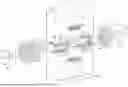
FIG. 1 is a perspective view of a muffler of the present invention with a first end panel and linear actuator in view;
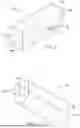
FIG. 2 is a perspective view of the muffler of FIG. 1 with a second end panel in view;
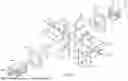
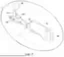
FIG. 3 is an exploded view of the muffler of FIG. 1;
FIG. 4 is an exploded view of selected internal components of the muffler of FIG. 3;
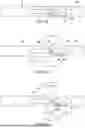
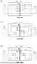
FIG. 5A is a side view of the muffler conduit and other selected components of FIG. 3 with all conduit segments aligned;
FIG. 5B is the same as FIG. 5A, but with a middle conduit segment displaced rotationally;
FIG. 5C is the same as FIG. 5B, but the middle conduit segment further displaced rotationally;
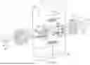
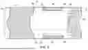
FIG. 6 is a perspective cross-section view of the muffler of FIG. 1 with parts removed to feature the acoustic insulation.
FIG. 7 is a closeup view of a linear actuator of the muffler of FIG. 1;
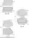
FIG. 8A is an exploded view of an acoustic insulation brick of a muffler of the present invention;
FIG. 8B is an exploded view of an alternate embodiment of an acoustic insulation brick of a muffler of the present invention;
FIG. 8C is an exploded view of another alternate embodiment of an acoustic insulation brick of a muffler of the present invention;
FIG. 9A is a side view of a muffler conduit and other selected components of an alternate embodiment of the improved muffler of the present invention with all conduit segments aligned;
FIG. 9B is the same as FIG. 9A, but with a middle conduit segment displaced vertically;
FIG. 9C is the same as FIG. 9B, but the middle conduit segment further displaced vertically;
FIG. 10A is variable muffler typical of the prior art with a flow control valve open; and
FIG. 10B is the prior art variable muffler of FIG. 10A with the flow control valve closed.
DETAILED DESCRIPTION OF THE INVENTION
With reference to FIGS. 1 and 2, one embodiment of an improved engine muffler 100 of the present invention comprises a body 50, an inlet comprising inlet pipe 80, an outlet comprising outlet pipe 20, and linear actuator 30. Linear actuator 30 may be rotationally mounted to the muffler at pivot connection 36.
Engine exhaust flows into the muffler through the inlet and out of the muffler through the outlet.
With reference to FIGS. 1, 2 and 3, body 50 may comprise side panels 51 and 52. Side panels 51 and 52 may comprise sheet-metal formed into “J” shapes and may be connected together so as to define a rectangular shaped tube with rounded corners. Body 50 may further comprise end panel 55 connected to the side panels at one end of the tube, and end panel 56 connected to the side panels at the other end of the tube. End panels 55 and 56 may each comprise sheet metal cut in rectangular shape having rounded corners that conform to the shape of rectangularly shaped tube formed by side panels 51 and 52 so that the assembly of side panels and end panels form an elongated chamber. The elongated chamber may have a longitudinal axis 101.
With further reference to FIG. 3, end panels 55 and 56 may each comprise a center through-hole 57 and 58, respectively, that may be aligned with each other on a longitudinal axis coinciding with the longitudinal axis 101 of the elongated chamber.
With reference to FIGS. 3 and 4, the muffler of the present invention may comprise a middle pipe 10 (also referred to herein as a “mid-pipe”). Pipes 20 and 80 may be connected to body 50, may be connected to end panels 55 and 56, respectively, and may be disposed through openings 57 and 58 of end panels 55 and 56, respectively. Peripheral conduit elements comprising inlet pipe 80, middle pipe 10 and outlet pipe 20 define a conduit, which defines a pathway for passage of exhaust gases and sound waves through the muffler.
Pipes 20 and 80 may be centered and axially aligned with one another along longitudinal axis 101. Mid-pipe 10 may be rotatable between a closed position and a range of open positions about a pivot axis 102 perpendicular to longitudinal axis 101. In the closed position, mid-pipe 10 is longitudinally aligned with pipes 20 and 80 to define a tubular pathway spanning all three pipes. In an open position, mid-pipe 10 is rotated out of alignment with pipes 20 and 80.
In the closed position, exhaust gases and sound waves can flow in the tubular pathway through the muffler so that sound can escape with least abatement, least acoustic modification and least quieting. In an open position exhaust gases and sound waves may communicate through an opening into the muffler chamber where sound can be absorbed by insulation and can be tuned and quieted by destructive interference and other acoustic phenomena. In the open position, gases may freely follow a path of least resistance through the muffler independently of the sound propagation, resulting in optimum quieting with less back pressure and less negative impact on engine performance. The improved muffler of the present invention provides for dissociation of exhaust flow and acoustics that was previously unavailable.
The improved muffler of the present invention provides a “straight pipe” pathway that is more isolated from acoustic chambers and free of internal obstruction, thus providing advantages over the prior art mufflers. As used herein to describe the improved muffler of the present invention, the term “straight pipe” comprises a continuous unbroken pathway that bypasses acoustic chambers for passage of exhaust flow through the muffler, which “straight pipe” pathway need not be straight, e.g., it may comprise curves, bends and corners.
With reference to FIGS. 3, 4 and 6, side panels 51 and 52, end panel 55, the perforated tube 92 and perforated plate 91 define a space for receiving acoustic insulation 71. Sound waves may be admitted into insulation 71 through the perforations in perforated tube 92 and perforated plate 91 to allow quieting by absorption of the sound waves by insulation 71. The side panels, perforated tube 94 and perforated plate 93 define a space for receiving acoustic insulation 72. Sound waves may be admitted into insulation 72 through the perforations in perforated tube 94 and perforated plate 93 to allow quieting by absorption of the sound waves by insulation 72.
Insulation 71 and 72 may be pre-formed to a desired shape or may comprise flexible pieces that may be packed into a space and take on shape of the space. The insulation may be ceramic insulation.
The space defined between side panels 51 and 52, perforated plates 91 and 93, perforated tubes 92 and 94, and pipes 20 and 80 define an acoustic chamber in which sound waves may experience reflection, refraction and diffraction and may be tuned and quieted by destructive interference wherein opposite sound waves cancel each other out. For example, a soundwave may reflect off the surface of perforated plate 91 and cause destructive interference with the oncoming soundwave, resulting in quieted soundwaves having reduced amplitude.
Perforated tubes 92 and 94 may be cylindrical tubes as shown, rectangular tubes, triangular tubes or tubes of any other shape.
With reference to FIG. 3, FIG. 6 and FIGS. 8A-8C one or more insulation “bricks” 40 may be disposed in the acoustic chamber and may be attached to side panels 51 and 52. With further reference to FIG. 8A, insulation brick 40 may comprise perforated sheet-metal 42 formed to define a rectangular space for receiving insulation 46. Insulation may be disposed in the rectangular space. With further reference to FIGS. 8A-8C, insulation bricks may comprise any shape.
The formed sheet metal of the insulation brick may be referred to as a “basket.” With further reference to FIGS. 8A-8C, basket 41 may have an open face through which insulation may be inserted into and removed from the basket. Alternatively, basket 41 may be completely enclosed.
A plurality of bricks may be disposed in the chamber to achieve the desired acoustic effect. Insulation bricks may be stacked adjacent to or upon other bricks and may be spaced apart from other bricks.
With reference to FIGS. 3-5C, the muffler may comprise first support member 60 connected to inlet pipe 80 and outlet pipe 20 and second support member 61 parallel to first support member 60 and connected to inlet pipe 80 and outlet pipe 20 on the diametrically opposite side of the pipes from first support member 60. Mid-pipe 10 may be rotatably connected to support members 60 and 61.
With reference to FIG. 4, mid-pipe 10 may comprise pivot pin 64 extending outward on pivot axis 102 and plate 63 attached on the mid-pipe's outer surface to strengthen the pipe adjacent to pin 64 and strengthen the pin connection to the pipe. Flanged bushing 65 may be disposed over pivot pin 64. Sleeve bushing 66 may be slidably disposed over flanged bushing 65. Pin 64, flange bushing 65 and sleeve bushing 66 may all be disposed in hole 68 of support member 60 forming a pivot connection between mid-pipe 10 and support member 60. The pivot connection comprises a plain bearing comprising flanged bushing 65 rotatably disposed in sleeve bushing 66.
With further reference to FIGS. 3-5C, in the closed position of FIG. 5A the ends of mid-pipe 10 may be flush with the ends of inlet pipe 80 and outlet pipe 20. With further reference to FIG. 5A-5C, the ends may be slanted at an angle so that mid-pipe 10 may be rotated counterclockwise about axis 102 (FIG. 4) without interference between the ends of the pipes. For example, with reference to FIG. 5A-5C, an end of a pipe may be on a slanted plane that is parallel to axis 102. The adjacent ends of pipes may be at corresponding angles so that the ends are flush when mid-pipe 10 is in the closed position. The angle must be sufficient so that no part of inlet pipe 80 and outlet pipe 20 would interfere with the path of any point on an end of mid-pipe 10 throughout its range of counterclockwise rotation.
Sealing strips 18 may be attached to mid-pipe 10 and may extend beyond the ends of the mid-pipe so as to form an overhang. Sealing strip 28 may be attached to outlet pipe 20 and may extend beyond the end of the outlet pipe so as to form an overhang. Sealing strip 88 may be attached to inlet pipe 80 and may extend beyond the end of the inlet pipe so as to form an overhang. The sealing strips may conform to the circumferential surfaces of the pipes so that the interior side of the strips are flush with the exterior side of the pipes when mid-pipe 10 is in the closed position so as to optimize the seal and minimize acoustic or fluid leakage from the pipes into the surrounding chamber. In an embodiment comprising cylindrical pipes, the concave side of the strips are flush with the convex side of the pipes.
In lieu of a sealing strip, a pipe may comprise an integral overhanging lip that may conform to the circumferential surfaces of an adjacent pipe so that the interior side of the lip may be flush with the exterior side of the adjacent pipe when mid-pipe 10 is in the closed position so as to optimize the seal.
With reference to FIG. 1, FIGS. 3 through 5C and FIG. 7, a mechanism may be provided for rotating mid-pipe 10. The mechanism may comprise a motorized linear actuator 30. Linear actuator 30 may comprise a motor 31 and reciprocating rod 32. Pivot link 33 may extend from pivot pin 64 and may comprise an eye (not shown) at the end for receiving clevis pin 35.
Reciprocating rod 32 may comprise a clevis 34 at the end for receiving pivot link 33 and clevis pin 35 to form a rotating joint with pivot pin 64. The linear actuator may be connected electronically to a controller located remotely, such as in the cab of a vehicle to which the muffler is attached, so that the opening and closing of the muffler conduit may be controlled from the cab to achieve the desired muffler performance. The opening may be controlled in either direction and may be set to any amount of opening over the range from closed to fully open.
With further reference to FIGS. 5A through 5C, three positions are shown over a range of positions from closed (FIG. 5A), to open (FIG. 5B), to more open (FIG. 5C). With further reference to FIG. 5C, the mid-pipe longitudinal axis is vertical. The amount of sound that is transmitted through the muffler without being transmitted into the chamber is a function of position, with said amount being the greatest in the closed position, least in the fully open position and ranging from greatest to least as the position changes from closed to open.
Alternatively, any suitable means for rotating mid-pipe 10 may be used, such as a rack and pinion.
With further reference to FIGS. 9A through 9C, an alternate embodiment of the improved muffler 200 provides for translational displacement of mid-pipe 210 to open the pathway. Inlet pipe 280 receives engine exhaust into the muffler and outlet pipe 220 discharges engine exhaust from the muffler. Bracket 263 is attached to mid-pipe 210 and comprises a female threaded part for receiving male threads of leadscrew 260 and an aperture for receiving guide rail 262. Leadscrew 260 is attached to the muffler vertically and comprises bevel gear for engaging bevel gear 231 of electric drive motor 230. Drive motor 230 is mounted on the muffler and drives leadscrew 260 rotationally in one direction to raise mid-pipe 210 and in the opposite direction to lower it. Translation of the mid-pipe is guided and stabilized by vertical guide rail 262. The drive motor may be connected electronically to a controller remotely located, such as in the cab of a vehicle to which the muffler is attached, so that the opening and closing of the muffler conduit may be reversibly controlled in either direction from the cab to achieve the desired muffler performance. The opening may be set to any amount of opening over the range from closed to fully open.
With further reference to FIGS. 9A through 9C, in the closed position, mid-pipe 210 is longitudinally aligned with pipes 220 and 280 to define a tubular pathway spanning all three pipes. In an open position, mid-pipe 210 is translated out of alignment with pipes 220 and 280. Three positions are shown over a range of positions from closed (FIG. 9A), to open (FIG. 9B), to more open (FIG. 9C).
The alternate embodiment of FIGS. 9A through 9C may comprise a sealing strip and may comprise an integral overhanging lip to optimize the seal between adjacent pipes when mid-pipe 210 is in the closed position as described in connection with the preferred swivel embodiment above.
While the invention has been particularly shown and described with reference to certain embodiments, it will be understood by those skilled in the art that various changes in form and details may be made to the invention without departing from the spirit and scope of the invention as described in the following claims.
Claims
We claim:1. An engine muffler, comprising:
a housing;
a chamber interior of the housing;
an inlet for receiving engine exhaust;
an outlet for discharging the engine exhaust;
a conduit defining a periphery of a pathway for fluid communication between the inlet and outlet;
said conduit comprising a first peripheral member defining a first part of the pathway periphery and a second peripheral member disposed in a first position defining a second part of the pathway periphery; and
said second peripheral member movable from the first position to a second position in which said conduit and chamber are in fluid communication through a space between the first member and second member.
2. The engine muffler of claim 1, further comprising:
said second peripheral member rotatable between the first position and the second position.
3. The engine muffler of claim 2, further comprising:
said conduit extending in a longitudinal direction; and
said second member rotatable about a pivot axis;
said pivot axis oriented at an angle to the longitudinal direction.
4. The engine muffler of claim 1, further comprising:
a first piece of insulation disposed in the chamber a distance away from the conduit.
5. The engine muffler of claim 4, further comprising:
a second piece of insulation disposed in the chamber a distance away from the conduit.
6. The engine muffler of claim 1, further comprising:
the housing comprising a first end panel disposed at a first end of the housing and a second end panel disposed at a second end of the housing;
a first perforated partition disposed in the chamber and spaced apart from the first end panel;
a second perforated partition disposed in the chamber between the first perforated partition and the second end panel;
a first piece of insulation disposed between the first end panel and first perforated partition; and
a second piece of insulation disposed between the second end panel and second perforated partition.
7. The engine muffler of claim 6, further comprising:
a first perforated tube disposed around the conduit between the first end panel and first perforated partition;
a second perforated tube disposed around the conduit between the second end panel and second perforated partition;
said first piece of insulation disposed between the first perforated tube and the housing; and
said second piece of insulation disposed between the second perforated tube and the housing.
8. The engine muffler of claim 7, further comprising:
said first perforated tube spaced radially outward from the conduit; and
said second perforated tube spaced radially outward from the conduit.
9. The engine muffler of claim 7, further comprising:
a third piece of insulation disposed between the first perforated partition and second perforated partition.
10. The engine muffler of claim 7, further comprising:
a perforated basket disposed between the first perforated partition and second perforated partition; and
a third piece of insulation disposed in the perforated basket.
11. The engine muffler of claim 1, further comprising:
said second peripheral member translatable between the first position and the second position.
12. The engine muffler of claim 1, further comprising:
a lip extending from the second peripheral member;
said lip disposed over a surface of the first peripheral member when the second peripheral member is in the first position.
13. An engine muffler, comprising:
a housing;
a chamber interior of the housing;
an inlet through the housing for receiving engine exhaust;
an outlet through the housing for discharging the engine exhaust;
a conduit defining a periphery of a pathway through the muffler for fluid communication between the inlet and outlet;
said conduit comprising a first conduit segment defining a first part of the pathway periphery, a second conduit segment in a first position adjacent to and aligned with the first conduit segment and defining a second part of the pathway periphery, and a third conduit segment adjacent to and aligned with the second conduit segment in a first position and defining a third part of the pathway periphery;
said second conduit segment in the first position providing fluid communication between the first conduit segment and third conduit segment;
said second conduit segment movable from the first position to a second position out of alignment with the first conduit segment and second conduit segment; and
said conduit and chamber in fluid communication through a space between the periphery of the first conduit segment and periphery of the second conduit segment when the second conduit segment is in the second position.
14. The engine muffler of claim 13, further comprising:
said conduit and chamber in fluid communication through a space between the periphery of the second conduit segment and periphery of the third conduit segment when the second conduit segment is in the second position.
15. An engine muffler, comprising:
an inlet conduit segment for receiving engine exhaust;
a middle conduit segment in a first position aligned with and adjacent to the inlet conduit segment; and
an outlet conduit segment for discharging the engine exhaust, said outlet conduit segment aligned with and adjacent to the middle conduit segment in the first position;
said middle conduit segment movable from the first position to a second position out of alignment with the inlet conduit segment and outlet conduit segment.
Images & Drawings included:

Sources:
- United States Patent and Trademark Office - verify current appl. status at the USPTO↗
Similar patent applications:
- » 20110126531
VARIABLE MUFFLER - » 20070261395
Diesel exhaust system variable backpressure muffler - » 20080156578
VARIABLE GEOMETRY MUFFLER FOR AN EXHAUST SYSTEM OF AN INTERNAL COMBUSTION ENGINE - » 20080314679
Variable Sound Muffler System - » 20090229911
VARIABLE GEOMETRY MUFFLER FOR AN EXHAUST SYSTEM OF AN INTERNAL COMBUSTION ENGINE - » 10833648
Muffler with variable acoustic properties - » 20200123948
Variable valve for muffler and dual muffler having the same - » 20140166392
VARIABLE VALVE APPARATUS AND MUFFLER PROVIDED WITH THE SAME
Recent applications in this class:
- » 20160341084 2016-11-24
Engine system with turbulence assisted damping of low frequency sound - » 20090313982 2009-12-24
Exhaust system for motorcycle - » 20070227810 2007-10-04
Vehicle exhaust system - » 20060048996 2006-03-09
Discharge gas check valve integral with muffler