DEVICE FOR CONTROLLING THE OSCILLATIONS OF A SWING OR ROCKER
US20260131253A1
2026-05-14
19/114,512
2023-08-22
Smart Summary: A portable device controls the swinging motion of swings and rockers for children. It can be easily attached to any existing swing without needing adjustments. The device uses a flywheel and an electric motor to create smooth oscillations. It includes a control module with a microcontroller that responds to an inertial motion sensor. This allows the swing to move in a controlled way, making it safer and more enjoyable for kids. 🚀 TL;DR
Abstract:
Portable mechanical swing controller for children swings, garden bench swings, infant rockers. The portable electromechanical device supporting and controlling oscillation of swings with one axis of rotation, installable on movable part of the swing only, can be installed on any ready-made swing, with no adjustment or calibration in the range of applicability, that is, the size and weight of the swing should be in the range of the device power. Device rotation is in one plane, device comprising housing, hardware for fastening the device to movable part of the swing fixed to an outer base surface of the housing; flywheel installed on an inner base surface of the housing, wherein an axis of rotation of the flywheel is connected to a shaft of an electric motor that is installed on the base, wherein the motor is connected to a control module with a microcontroller connected to an inertial motion sensor.
Applicant:
Interested in similar patents?
Get notified when new applications in this technology area are published.
Classification:
A63G9/16 » CPC main
Swings Driving mechanisms, such as ropes, gear, belt, motor drive
A47C3/0251 » CPC further
Chairs characterised by structural features; Chairs or stools with rotatable or vertically-adjustable seats; Rocking chairs with seat, or seat and back-rest unit elastically mounted in a rigid frame driven by electric motors
A47C3/0255 » CPC further
Chairs characterised by structural features; Chairs or stools with rotatable or vertically-adjustable seats; Rocking chairs with seat, or seat and back-rest unit elastically mounted in a rigid frame pivotally mounted in the base frame, e.g. swings
A47C3/027 » CPC further
Chairs characterised by structural features; Chairs or stools with rotatable or vertically-adjustable seats; Rocking chairs with seat, or seat and back-rest unit elastically mounted in a rigid frame with curved rocking members between seat and base frame
A47D9/057 » CPC further
Cradles ; Bassinets with rocking mechanisms driven by electric motors
A47C3/025 IPC
Chairs characterised by structural features; Chairs or stools with rotatable or vertically-adjustable seats; Rocking chairs with seat, or seat and back-rest unit elastically mounted in a rigid frame
A47D9/02 IPC
Cradles ; Bassinets with rocking mechanisms
Description
FIELD OF THE INVENTION
The invention relates to swing attachments, namely to a portable mechanical swing controller, and can be used for children swings, garden bench swings, infant rockers, etc. Hereinafter, the aforementioned devices are named “swing” and comprise a mechanical system capable of oscillating about a position of equilibrium, intended for domestic use, primarily recreational one. In particular, the claimed device works with a swing having one axis of rotation in the form of a seat suspended from poles or a crossbar, or a cradle (chair, seat, various toys, such as a horse, car, etc.) mounted on supports with U-shaped slides.
BACKGROUND OF THE RELATED ART
The following technical solutions are known from the conventional art.
Automated swinging carousels are known featuring complex design, where a part of the swing mechanical system is installed on a movable part of the amusement ride and another part is installed on a fixed support, wherein the swing mechanism is most frequently the integral part of the device and is supplied together with the swing.
For example, a drive mechanism for a baby swing is known that is mounted on the swing frame and makes the rocker move via electromagnetic control. A lever connected to the swing and a drive mechanism connected to the couple of the rocker arms enable to achieve a certain range of oscillatory motion of the rocker seat. The drive mechanism consists of a housing with a control button, a rotating shaft, a transmission system, and a control device. The rotating shaft is connected either to the rocker arm end or directly to the swing seat to drive the arm into oscillatory or rotational motion (see US patent application publication No. 2007010338 A1, publ. Jan. 11, 2007).
Swings are also known with a protective casing installed coaxially with the swinging axis of rods with a seat with the possibility of joint movement with them, enveloping the movable swing parts from the outside, provided with two stand-alone hangers fixed on the bar and stops interacting with the seat elements, the protective casing is equipped with two stand-alone articulated hangers fixed on the bar and stops installed inside the casing and interacting two-way with the seat elements, on the crossbar a copier is installed that is equipped with shaped grooves of different depth, an electric motor rotating the drum with an elastic plate, on the swing rod crossbars a copier pin is installed in the guiding holes, which interacts its upper end with the copier grooves and its lower end-with the elastic plate of the rotating drum at the moment of forward-and-down seat movement and maximum protrusion of the copier pin (see patent RU No. 2537876, publ. Jan. 10, 2015).
The main disadvantage of the claimed solutions is the need for a mechanical connection between the movable part of the swing and the swing frame or the environment. The complexity of installation and maintenance of such a connection causes creating complex products containing a movable part and a frame. Thus, the swing and the device supporting oscillation constitute a single device. As a result, the solutions known from prior art are intended either for controlling the oscillations of very small swings (infant cradles) or, on the contrary, for industrial applications in the entertainment industry (amusement rides).
SUMMARY OF THE INVENTION
The object of the claimed invention is providing a compact mechanical vibration controller manufactured and provided separately from a swing, the design of which enables its installation on the seat/cradle of any swing, including infant cradles, garden bench swings, children swings, rocking chairs, etc.
The object is solved by the fact that all elements of the mechanism, including control and monitoring elements, are placed in one housing, and structurally there is no mechanical connection of the device with the swing frame or external environment.
An automatic swing module mounted on the lower surface of the swing seat and featuring a housing with a pair of toothed rails mounted on its bottom sides can be regarded as the closest prior art of the claimed device. A platform with a motor mounted on it is also provided. The motor rotor protrudes out of the platform sides with gears fixedly connected to it. These gears are conditioned to engage with and move along toothed rails between the front and rear portions of the rotary assembly. The platform is also equipped with a limit switch. The limit switch is necessary to make the platform move in the opposite direction when it is pressed. The platform is moved only when the motor is powered by the battery, which is determined by a switch positioned on the rear face of the module (see U.S. Pat. No. 6,024,648, publ. Feb. 15, 2000).
The device disadvantage is the unnecessary transforming rotary motion into translational motion. The motor uses the rotational motion and transforms into rail translational motion, which in turn is again transformed into rotational motion of the swing.
The closest prior art of the claimed solution in terms of the principle of operation discloses a device featuring a generator of oscillations that comprises a mechanism installed in a housing fixed on the swing seat and including one of the following: a gear with manual winding, a piston, a pendulum, a motor, gears, and a pump (see the publication of patent application US No. 2012119549A1, published on Jul. 22, 2014).
The above document also describes transforming rotary motion into translational motion, and inefficiently: the motor does the work by moving the weights along a non-operational axis, perpendicular to the required motion. The devices described feature low efficiency. In contrast to existing devices, in the claimed device the rotational motion of the flywheel is transformed directly into swing rotational motion.
The technical problem solved by the claimed invention is providing the possibility to supplement any swing featuring one axis of rotation in the form of a seat suspended from poles or a bar or mounted on U-shaped slides (various kinds of rocking chairs or children's shooflies), with an automated device making it possible to maintain a given oscillation amplitude of the seat/cradle with no user's effort. The amplitude for the device can be manually set by a user, also, the device can be switched to the mode of memorizing the current amplitude, thus the calculated amplitude is saved in the device permanent memory and is not reset when the device is switched off.
The object is achieved by a device featuring a mechanism based on reactive torque, as well as mass inertness and resonance.
The technical result is creating a portable electromechanical device supporting and controlling the oscillation of different kinds of swings with one axis of rotation, with a possibility to install the device on the movable part of the swing only. In addition, the device is universal, the design makes it possible to install it on any ready-made swing, there is no need for adjustment and calibration in the range of applicability, that is, the size and weight of the swing should be in the range of the device power (matching the device power to a particular type of swing).
The claimed technical result is achieved due to the design of the device controlling swing mechanical oscillations featuring the possibility of rotation in one plane, comprising a housing, on the outer base surface whereof there are fixed hardware for fastening the device to the movable part of the swing, and on the inner base surface a flywheel is installed, the axis of rotation whereof is connected to the shaft of an electric motor installed on the base, the motor is connected to a control module including a microcontroller connected to an inertial motion sensor.
In a particular implementation of the invention, the inertial motion sensor comprises a gyrosensor.
In a particular implementation of the invention, the inertial motion sensor comprises an accelerometer.
Additional features and advantages of the claimed solution are described in the following disclosure and proved by the actual practice of the invention. These advantages and improvements can be achieved by intelligent agents constructed and trained following the claimed method, precisely following the disclosure, along with the accompanying claims and drawings.
BRIEF DESCRIPTION OF THE ATTACHED DRAWINGS
The accompanying drawings, which are included to provide a further understanding of the invention and are incorporated in and constitute a part of this specification, illustrate embodiments of the invention and together with the description serve to explain the principles of the invention.
In the drawings:
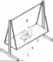
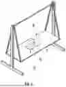
FIG. 1—General view of a swing where the claimed device can be mounted.
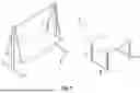
FIG. 2—General view and installation diagram for mounting the device on the movable part of the swing.
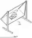
FIG. 3—Principle of operation of the mechanical oscillation control device.
DETAILED DESCRIPTION OF EMBODIMENTS OF THE INVENTION
Reference will now be made in detail to the preferred embodiments of the present invention, examples of which are illustrated in the accompanying drawings.
FIG. 1 shows a general view of a swing whereon the claimed device can be mounted. The common feature between the above types of swings is a movable part 1, which can comprise a seat (with backrest/without backrest), a cradle, toys (horses, cars, etc.), as well as a bench with or without backrest, and other versions. This movable part 1 may be attached with rigid or flexible hangers 2 to a frame 3 or mounted on supports with U-shaped slides 4.
In both cases, the claimed device is mounted with a rigid attachment to any place of the movable part 1 of the swing, preferably on the lower surface of the movable part 1, so that the flywheel axis of rotation is perpendicular to the plane of the swing movement. For illustrative purposes, FIG. 2 generally shows the device mounted on the upper surface of the movable part 1. The device includes a housing (not shown), the base 5 whereof (on its outer surface) comprises rigid fastenings for attaching to the movable part with bolts or self-tapping screws directly to the seat. This option is used for long-time device operation on a certain swing, as in this case the seat is damaged. Another option provides the possibility to attach the housing to the seat by steel cables with tensioners or tension straps. In this case, the seat is not damaged, and the device can be used on various swings. In the case of small oscillation amplitude (e.g., when used with a garden swing), the device can simply be placed on the seat or suspended from the seat with non-stretchable straps.
The housing may be made of plastic. For installation in public spaces, a vandal-resistant steel housing is available. A waterproof option can also be provided for outdoor applications.
On the inner surface of the housing base 5, a control module 6 of the device is mounted, associated with an electric motor 7, on the shaft of which a flywheel 8 is mounted.
The electric motor comprises a brushless three-phase motor allowing torque control.
Almost any electric motor can be used, including commutator motors and AC motors. For motors not allowing direct torque control, this can be done indirectly by controlling the motor speed.
The preferred flywheel 8 option comprises a thin-walled cylinder, since this shape provides the maximum moment of inertia about the cylinder axis. For practical implementation, it is possible to use thick-walled steel pipes. Specifically, a section of steel pipe with a weight of about 3.5 kg, a diameter of 159 mm, a length of 95 mm, and a thickness of 10 mm is used. Another example of a flywheel is the axisymmetric placement of several heavy weights. A flywheel made of high density material such as metals, cement, concrete, composites, etc. can be used to reduce the device size.
The control module comprises an electrical circuit including a microcontroller analyzing the data received from the inertial motion sensor (IMD) and transmitting commands to the electric motor that converts the signals into the required motion parameters (torque and direction), as well as memory board. The IMD comprises a gyrosensor (gyroscope) or accelerometer. In a particular case, both types of sensors can be installed.
The device control module can do the following:
-
- 1. Detect the current oscillation profile of a mechanical system using IMD. If harmonic oscillations are detected, their amplitude, frequency, and phase are calculated.
- 2. Maintain a given swing amplitude by counteracting the oscillation damping caused by friction in the system. Functionally, it looks like an endlessly swinging swing.
- 3. The oscillation amplitude can be changed as needed (in device settings).
The device can be powered externally or internally (battery). In particular, for indoor use of the device, powering by a mains cable is preferred, while for outdoor use, such as for garden or children's swings, battery is preferred.
The microcontroller of the control module is connected to the control panel either with wires or wirelessly. The control panel provides buttons to turn the unit on/off, and to switch the unit to the amplitude setting mode. The functionality of the remote control can be extended with on-the-fly amplitude change buttons, etc. The remote control can also be supplemented or replaced by wireless control, e.g., from a smartphone via Bluetooth.
Invention Implementation
The following physical principles are used in the device operation:
-
- inertia forces;
- reactive torque;
- resonance.
Instead of a mechanical connection to the swing frame or the environment, the inert mass property is used to detect motion using an inertial motion sensor and to control motion with a flywheel. A torque generated by the electric motor is applied to the flywheel, causing flywheel angular acceleration (arrow 9, FIG. 3). The moment of inertia of the flywheel counteracts the movement, causing a reactive (opposite in direction and equal in modulus) torque in the electric motor, which transmits torque to the swing through the rigid mount, causing the swing angular acceleration (arrow 10, FIG. 3). By synchronizing the generated torque with the natural frequency of oscillation of the moving part of the swing, the device effectively changes the mechanical energy of the oscillations, and thus their amplitude.
It should also be appreciated that various modifications, adaptations, and alternative embodiments thereof may be made within the scope and spirit of the present invention. The invention is further defined by the following claims.
Claims
What is claimed is:1. A device for controlling mechanical oscillations of a swing made with the possibility of rotational motion in one plane, comprising:
a housing;
hardware for fastening the device to a movable part of the swing fixed to an outer base surface of the housing;
flywheel installed on an inner base surface of the housing,
wherein an axis of rotation of the flywheel is connected to a shaft of an electric motor that is installed on the base,
wherein the motor is connected to a control module with a microcontroller connected to an inertial motion sensor.
2. The device of claim 1, wherein the inertial motion sensor is a gyrosensor.
3. The device of claim 1, wherein the inertial motion sensor is an accelerometer as.
4. The device of claim 1, wherein the flywheel is a thin-walled cylinder.
5. The device of claim 1, wherein the flywheel is an axisymmetric arrangement of multiple heavy weights.
Images & Drawings included:
Sources:
- United States Patent and Trademark Office - verify current appl. status at the USPTO↗
Recent applications in this class:
- » 20220410019 2022-12-29
Amusement ride for children - » 20220395757 2022-12-15
Swing control method and apparatus - » 20200289949 2020-09-17
Vertical motion drive system for a ride system - » 20200171396 2020-06-04
Multi-degree of freedom elevator ride system - » 20200129870 2020-04-30
Swinging drive control apparatus and method - » 20200129869 2020-04-30
MOTORIZED SMART SWING - » 20200094153 2020-03-26
Amusement ride - » 20190291012 2019-09-26
Amusement device - » 20160107091 2016-04-21
Electromagnetic swing - » 20150174497 2015-06-25
Playground swing