RIDGED TUNDISH STOPPER
US20260131375A1
2026-05-14
19/482,005
2024-05-14
Smart Summary: A new type of stopper has been designed for use in a tundish, which is a container used in metal casting. This stopper features ridges that touch the slag, a byproduct of metal production. Each ridge is smaller than half the width of the stopper, allowing for better flow control. The design of these ridges helps reduce swirling movements in the liquid, which can wear out the stopper more quickly. As a result, this innovation not only improves the stopper's performance but also extends its lifespan. 🚀 TL;DR
Abstract:
A stopper (1) is provided that includes ridges (12) in contact with the slag in a tundish (60). Each ridge (12) has a radial extension (21) that is less than half a radius (20) of the stopper (1) measured at the ridge (12). The ridges (12) rise and drop around the stopper (1). The ridges (12) decrease the creation of vortices by the stopper (1) and increase thus its lifetime.
Inventors:
- Martin Kreierhoff 3 🇧🇪 Ghlin, Belgium
- Marcel Rave 3 🇧🇪 Ghlin, Belgium
- Johan Richaud 3 🇧🇪 Ghlin, Belgium
Assignee:
- VESUVIUS GROUP S.A. 31 🇧🇪 Ghlin, Belgium
Applicant:
Interested in similar patents?
Get notified when new applications in this technology area are published.
Classification:
B22D41/18 » CPC main
Casting melt-holding vessels, e.g. ladles, tundishes, cups or the like; Closures stopper-rod type, i.e. a stopper-rod being positioned downwardly through the vessel and the metal therein, for selective registry with the pouring opening Stopper-rods therefor
B22D41/20 » CPC further
Casting melt-holding vessels, e.g. ladles, tundishes, cups or the like; Closures stopper-rod type, i.e. a stopper-rod being positioned downwardly through the vessel and the metal therein, for selective registry with the pouring opening Stopper-rod operating equipment
Description
FIELD OF THE INVENTION
The present invention relates to a stopper for controlling the flow of molten metal through an exit hole of a tundish towards a mould or a casting tool.
DESCRIPTION OF PRIOR ART
A stopper is typically used to control the flow of liquid metal flowing out of a tundish towards a mould or a casting tool. The stopper comprises an elongated body having a lower end designed to close an exit hole at the bottom of the tundish. The stopper moves up and down, to close or open the exit hole.
The lower end of the stopper is immerged in the liquid metal. The upper end of the stopper is in the air. An intermediate part of the stopper is in contact with a slag layer floating on the liquid metal at the interface with air. The slag, flowing down in vortices along the stopper, erodes chemically and mechanically the stopper, reducing locally its diameter and decreasing its lifetime. Moreover, when the liquid metal level is low, the slag may be driven down by vortices into the exit hole.
In order to inhibit vortices, document CN110788314 A discloses a stopper having large blocking table and rib plates.
In order to increase the lifetime of the stopper, document KR20140140429A discloses a stopper made of an elongated body and a removable protection piece at the level of the slag. The slag is expected to erodes the removable protection piece, which can then be removed and replaced by a new one.
CN106735153A describes a stopper with rings aiming at facilitating floating of inclusions in order to improve the cleanliness of the molten steel.
A problem of these known stoppers is that they comprise a thick relief strongly increasing locally the diameter of the stopper, and thus its resistance to motion in the liquid metal. A fine control of the stopper up and down motion is thus impossible.
SUMMARY OF THE INVENTION
It is an object of the present invention to provide a stopper reducing the vortices along its lateral wall.
It is an object of the present invention to provide a stopper having an especially long lifetime.
The invention relates to a stopper for controlling the flow of liquid metal out of a tundish, the stopper extending in an axial direction between an upper end and a lower end and being radially limited by a lateral wall comprising a plurality of ridges, wherein the ridges extend at least partially along a circumferential direction on the lateral wall, wherein at least two of the ridges are separated along the axial direction by a gap, wherein each ridge has a radial extension being at least 0.01 times the radius of the stopper taken at said ridge, wherein each ridge has an axial extension being at least 0.01 times the diameter of the stopper at the uppermost ridge, characterized in that each ridge has a radial extension that is less than half a radius of the stopper taken at said ridge, at least one part of a least one of the ridges rises with the circumferential direction and at least one part of a least another one of the ridges drops with the circumferential direction, and each ridge extends between one or more upper points located closest to the upper end and a corresponding number of one or more lower points located closest to the lower end.
The inventors have shown, through simulations, that such a plurality of ridges, extending up and down, break up large vortices which create slag entrainment along the lateral wall and thus strong erosion. Moreover, they have shown that the average wall shear stress on the stopper is decreased with respect to a stopper without such ridges. They have also shown that this oscillating shape of the plurality of ridges prevents the detachment of stable large vortices in the wake past of the stopper, which enhances the risk of slag entrainment.
The stopper according to the invention does not comprise any thick relief since all ridges are radially limited in size by half of the radius of the stopper at their level. This absence of thick relief provides a low resistance to motion and thus a good response to control. This upper limit in the radial dimension of every ridge of the claimed stopper is not present in the stopper of KR20140140429A where the removable protection piece, reference 200, provides an extremely large ridge. In this prior art document, the “thread”, reference 110, is not intended to be used without the removable protection piece or to be in contact with the slag, and forms a single ridge and not a plurality of ridges.
In the invention, the ridges, which extend at least partially along a circumferential direction and are thus not only axial, form an upper side and a lower side of gaps. The internal side of the gaps is the lateral wall between the ridges and the external side of the gaps is open. The gaps accommodate a volume of liquid metal and/or slag which tend to remain there during the vertical motion of the stopper, decreasing thus the erosion on the stopper. The radial extension of a ridge is measured with respect to the deepest point of all the gaps adjacent to said ridge.
The at least two of the ridges that are separated along the axial direction are preferably aligned axially but not necessarily completely aligned axially. The stopper is preferably one piece. The stopper is preferably moulded in one piece. The ridges are preferably integral with the stopper, and especially with the upper end and the lower end.
The stopper does not comprise any protrusion having a radial extension that is more than half a radius of the stopper taken at said protrusion. The stopper does not comprise any removable protection piece around the lateral wall. The ridges are preferably not helicoidal.
The lateral wall is an external surface. The ridges are preferably designed to be in contact with the slag at the top surface of the liquid metal. The ridges extend partially along the circumferential direction and partially along the axial direction on the lateral wall.
The plurality of ridges creates an oscillating shape along the lateral wall. The ridges extend in a shape that oscillates between the one or more upper points and the one or more lower points. They extend as a wave (or at least part of a wave) between the one or more upper points and the one or more lower points.
In an embodiment, the lateral wall has a first diameter at the uppermost ridge, and a second diameter at the lowermost ridge, the first diameter being higher than the second diameter. In other words, the lateral wall narrows when going down at the level of the ridges. This narrowing of the stopper decreases the diameter in the middle region, and thus the weight of the stopper.
In an embodiment, the lateral wall comprises two elongated passages delimited circumferentially by at least half of the ridges. The stopper can comprise more than two elongated passages. The elongated passages are locations along the circumference of the lateral wall where the liquid is less disturbed by the vertical motion of the ridges. In other words, they are passages for the liquid to remain more stable around the stopper. They therefore decrease the effect of wave creation due to this vertical motion.
In an embodiment, the ridges are fully accommodated in a recess on the lateral wall.
They do not extend radially further than the recess. This shape is especially interesting to avoid waves.
The stopper comprises at least two ridges closer to the upper end than to the lower end. They are vertically located at a steady state casting level of the slag in the tundish.
The invention also relates to a system for continuous casting comprising:
-
- a tundish comprising an exit hole;
- liquid metal in the tundish, the liquid metal having a top surface;
- a stopper as described in the present document, configured for closing the exit hole and disposed in such a way that the top surface of the liquid metal is in contact with at least some of the ridges; and
- a support holding the stopper.
In an embodiment, the system further comprises:
-
- a mould or casting tool below the tundish configured to receive liquid metal flowing through the exit hole;
- a sensor for sensing the liquid metal in the mould or casting tool; and
- a data processing system connected to the sensor and to the support and configured for controlling the support as function of information received from the sensor.
With such a system, the vertical motion of the stopper, and consequently the metal flow in the exit hole, is controlled based on measurement in the mould or casting tool.
The invention also relates to a method for controlling a stopper as described in the present document in a system as described in the present document, wherein the support moves the stopper vertically, preferably with a frequency between 0.1 Hz and 100 Hz.
With the stopper according to the invention, the vertical motion of the stopper is not impaired by any thick protrusion, which is especially advantageous for quick oscillations.
In an embodiment,
-
- the sensor sends information to the data processing system,
- the data processing system controls the support based on said information in such a way that the support moves the stopper vertically.
BRIEF DESCRIPTION OF THE DRAWINGS
These and further aspects of the invention will be explained in greater detail by way of example and with reference to the accompanying drawings in which:
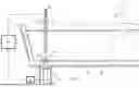
FIG. 1 is a vertical cross-section of a tundish,
FIG. 2 is a vertical cross-section of a part of a stopper,
FIG. 3 is a horizontal cross-section of a part of a stopper, along the plan shown III-III at FIG. 2,
FIG. 4 is a 3D view of a part of a stopper,
FIG. 5 is a 3D view of a part of a stopper,
FIG. 6a is a 3D view of a part of a stopper,
FIG. 6b is a 3D view of a part of a stopper,
FIG. 6c is a 3D view of a part of a stopper,
FIG. 7a is a top view of a part of a tundish with a stopper according to the prior art,
FIG. 7b is a top view of a part of a tundish with a stopper,
FIG. 8a is a vertical cross-section of a part of a tundish with a stopper according to the prior art,
FIG. 8b is a vertical cross-section of a part of a tundish with a stopper,
FIG. 9a is a vertical cross-section of a part of a tundish with a stopper according to the prior art,
FIG. 9b is a vertical cross-section of a part of a tundish with a stopper,
FIG. 10 is a plot showing a simulation of the volume of the high energy vortices as function of time,
FIG. 11a is a top view of a part of a tundish with a stopper according to the prior art,
FIG. 11b is a top view of a part of a tundish with a stopper,
FIG. 12 is a plot showing a simulation of the area of the high energy vortices on the top surface of the liquid as function of time,
FIG. 13a illustrates a lateral wall of a stopper of the prior art, on which the wall shear stress is represented,
FIG. 13b illustrates a lateral wall of a stopper, on which the wall shear stress is represented, and
FIG. 14 is a plot showing a simulation of the wall shear stress as function of time.
DETAILED DESCRIPTION OF PREFERRED EMBODIMENTS
The present invention will be described with respect to particular embodiments and with reference to certain drawings but the invention is not limited thereto. The drawings described are only schematic and are non limiting. In the drawings, the size of some of the elements may be exaggerated and not drawn on scale for illustrative purposes.
Furthermore, the terms first, second, third and the like in the description and in the claims, are used for distinguishing between similar elements and not necessarily for describing a sequential or chronological order. The terms are interchangeable under appropriate circumstances and the embodiments of the invention can operate in other sequences than described or illustrated herein.
Furthermore, the various embodiments, although referred to as “preferred” are to be construed as exemplary manners in which the invention may be implemented rather than as limiting the scope of the invention.
The term “comprising”, used in the claims, should not be interpreted as being restricted to the elements or steps listed thereafter; it does not exclude other elements or steps. It needs to be interpreted as specifying the presence of the stated features, integers, steps or components as referred to, but does not preclude the presence or addition of one or more other features, integers, steps or components, or groups thereof. Thus, the scope of the expression “a device comprising A and B” should not be limited to devices consisting only of components A and B, rather with respect to the present invention, the only enumerated components of the device are A and B, and further the claim should be interpreted as including equivalents of those components.
FIG. 1 represents a tundish 60. In the tundish 60, liquid metal 65 flows from a ladle shroud 62 to an exit hole 61. The top surface 66 of the liquid metal is a layer of slag. A stopper 1 controls the flow of metal through the exit hole 61.
The stopper 1 comprises a refractory material. The stopper 1 has an upper end 91 (which may be called first end) connected to a support 69 that moves the stopper 1 vertically, and a lower end 92 (which may be called second end) able to close the exit hole 61. The stopper 1 may comprise a sleeve 93, preferably located closer to the upper end 91 than to the lower 92, and made of a material more resistant to erosion than the rest of the stopper 1. The stopper 1 comprises a through hole 94 for gas injection. The exit hole 61 is connected to a tundish upper nozzle 71 and a submerged nozzle 70 leading the liquid metal to a mould 64 or casting tool.
The mould 64 or casting tool below the tundish 60 receives the liquid metal flowing through the exit hole 61 when it is not totally obstructed by the stopper 1. A sensor 67 detects at least one characteristic of the liquid metal 72 in the mould 64 or casting tool, for example the metal level. The sensor 67 sends information to a data processing unit 68 that controls the support 69. The information is thus used to move the stopper 1 vertically. The vertical position of the stopper controls the flow into the exit hole 61. In addition to its vertical motion regulating the flow through the exit hole 61, the stopper 1 may oscillate vertically (which may be called “dithering”). The frequency of the oscillations is preferably in the range from 0.1 Hz to 100 Hz, more preferably from 0.2 Hz to 10 Hz, and its amplitude in the range from 0.2 to 10 mm.
FIGS. 2 and 3 illustrate a stopper 1 in an embodiment of the invention. The stopper 1 has an axis 100. The stopper 1 is hereby described referring to an axial direction 101 (which is vertical in use), a radial direction 102 (horizontal in use and extending away from the stopper axis 100), and a circumferential direction 103 (horizontal and perpendicular to the radial direction 102).
The stopper 1 has a lateral wall 10 shaped by ridges 12 that protrude radially. The lateral wall 10 circumferentially surrounds the stopper 1. Considering any of the ridges 12, its radial extension 21 can be determined and the radius 20 of the stopper 1 at the considered ridge 12 can also be determined. In the invention, the radius 20 of the stopper 1 at any considered ridge 12 is more than twice the radial extension 21 of said considered ridge 12, preferably more than three times the radial extension 21 of said considered ridge 12, more preferably more than four times the radial extension 21 of said considered ridge 12. As visible at FIG. 2, the radius 20 of the stopper 1 measured at a ridge 12 may be equal the sum of the radial extension 21 of said ridge 12 with the radius up to said ridge 12.
The stopper 1 comprises at least two ridges 12. It may comprise two, three, four or five ridges 12. The stopper 1 comprises a group 16 of ridges 12 comprising at least two adjacent ridges 12 separated along the axial direction 101 by a gap 19. Preferably, the stopper 1 comprises less than 100 ridges. The ridges 12 are not totally along the axial direction 101: any of the ridges 12 is partially circumferential and partially axial. At least some of the ridges 12 may be in the sleeve 93.
For conciseness in the present document, the diameter 22 of the stopper 1 at the uppermost ridge 121 is identified hereby as DU. Preferably, the ridges 12 have an axial extension 41 between 0.01 DU and 0.4 DU, preferably between 0.03 DU and 0.24 DU, more preferably between 0.05 DU and 0.16 DU. The axial extension 41 is preferably measured as close as possible to the axis 100, i.e., at the beginning of the ridge 12. Preferably, the gaps 19 have an axial extension 42 between 0.02 DU and 0.3 DU, preferably between 0.04 DU and 0.3 DU, more preferably between 0.05 DU and 0.1 DU.
For conciseness in the present document, the radius 20 of the stopper 1 at a ridge 12 is identified hereby as RS. Preferably, each ridge 12 have a radial extension 21 between 0.01 RS and 0.4 RS, preferably between 0.05 RS and 0.3 RS, more preferably between 0.1 RS and 0.2 RS.
The stopper 1 may be cylindrical or have a conical vertical section, at least at the level of the ridges 12, in such a way that its diameter 22 at the uppermost ridge 121 is higher than its diameter 23 at the lowermost ridge 122. The conical vertical section may be such that an angle α between 1° and 30° exists between the lateral wall 10 and the axial direction 101.
In some embodiments of the invention, the ridges 12 have an angular extension, in a plan perpendicular to the axis 100, (lower than 350°, possibly lower than 180°. The ridges 12 are thus ending, circumferentially, at circumferential ends 15. Examples of such embodiments are visible on FIGS. 3 and 4. In other embodiments of the invention, the ridges 12 have an angular extension in a plan perpendicular to the axis 100, B, equal to 360°, as illustrated on FIGS. 5 to 6c.
FIG. 4 illustrates ridges 12 that are partially circumferential and partially axial. They delimit, circumferentially, elongated passages 13. The elongated passages 13 preferably have an angular extension, in a plan perpendicular to the axis 100, higher than 2° and lower than 30°. The elongated passages 13 are circumferentially delimited by some of the ridges 12, for example by at least half of the ridges 12. In other words, they are located between the circumferential ends 15 of some of the ridges 12, for example of half of them. They are preferably parallel to the axis 100. In FIG. 4, each ridge 12 extends between one upper point 31 and one lower point 32, and some of the ridges 12 rises with the circumferential direction 103 and some of the ridges 12 drops with the circumferential direction 103.
FIG. 5 and FIGS. 6a-6c illustrate ridges 12 having a shape that oscillates between two upper points 31 (“upper” means closest to the upper end 91) and two lower points 32 (“lower” means closest to the lower end 92). These ridges 12 have two parts that rise with the circumferential direction 103 and two parts that drop with the circumferential direction 103. Within the scope of the present invention, each ridge 12 may for example oscillate between one upper point and one lower point, between two upper points and two lower points; or in general, between N upper point(s) and N lower point(s), N being an integer from 1 to 10.
FIGS. 6a-6c illustrate a line 200 which is tangential to the lateral wall 10 above and below the ridges 12. Considering all the tangential lines, a tangential cone or cylinder could be drawn. In FIGS. 6a and b, the lateral wall 10 comprises a recess 14. The recess 14 is due to a concavity of the lateral wall 10, i.e., the recess 14 is a recess with respect to the tangential cone or cylinder. In FIGS. 6a and b, the ridges 12 are fully accommodated in the recess 14. In other words, they do not protrude out of the tangential cone or cylinder. In FIG. 6a, the ridges 12 are radially internal with respect to the tangential cone or cylinder; in FIG. 6b, they are radially tangential with respect to the tangential cone or cylinder. In FIG. 6c, the ridges 12 protrude out of the tangential cone or cylinder.
FIG. 6c illustrates the axial distance 18 between an upper point 31 and a lower point 32 of one of the ridges 12. Preferably, for each ridge 12, the axial distance 18 between any upper point 31 and any lower point 32 is between 0.01 and 0.4 times the diameter 22 of the stopper 1 at the uppermost ridge 121, preferably between 0.03 and 0.24 times the diameter 22 of the stopper 1 at the uppermost ridge 121, more preferably between 0.05 and 0.16 times the diameter 22 of the stopper 1 at the uppermost ridge 121.
Within the scope of the present invention, and as illustrated on FIGS. 5 to 6c, each ridge 12 is preferably parallel, more preferably identical, to the one or two ridges 12 which are axially adjacent to it.
FIGS. 7 to 14 compare Computational Fluid Dynamics (CFD) simulations for a stopper 2 without any ridge (called below standard stopper) and a stopper 1 with ridges 12 as illustrated at FIG. 6c (called below ridged stopper). The ladle shroud is on the right of these figures, the flow coming thus from right to left.
FIGS. 7a (for the standard stopper) and 7b (for the ridged stopper) show the top surface 66; FIGS. 8a (for the standard stopper) and 8b (for the ridged stopper) show a central section of the tundish. They show velocity contours in m/s and arrows indicating the flow direction. Vortices appear in both cases in the wake behind the stopper.
FIGS. 9a (for the standard stopper) and 9b (for the ridged stopper) show a central section of the tundish with, in black, the high energy vortices. It appears that the ridges 12 reduce the creation of large vortices which create a risk for slag entrainment. The volume of the high energy vortices as function of time is shown at FIG. 10. Table I provides the average volume and the maximum volume deduced from the plot of FIG. 10.
| TABLE I | ||
| Standard stopper 2 | Ridged stopper 1 | |
| Average volume of the | 1.96 | 1.66 |
| high energy vortices (liter) | ||
| Maximum volume of the | 3.81 | 2.98 |
| high energy vortices (liter) | ||
FIGS. 11a (for the standard stopper) and 11b (for the ridged stopper) show a top view of the tundish with, in black, the high energy vortices, and with arrows indicating the flow direction. It appears that the ridges 12 reduces the creation of high energy vortices on the top surface in the wake past the stopper 1. Table II provides the area with enstrophy ζ>2s−2 in these figures.
| TABLE II | ||
| Standard | Ridged | |
| stopper 2 | stopper 1 | |
| Area with enstrophy ξ > 2s−2 (cm2) | 459 | 225 | |
The area of the high energy vortices on the top surface 66 as function of time is shown at FIG. 12. Table III provides the average area and the maximum area deduced from the plot of FIG. 12.
| TABLE III | ||
| Standard | Ridged | |
| stopper 2 | stopper 1 | |
| Average area of the high energy | 324 | 287 | |
| vortices on the top surface (cm2) | |||
| Maximum area of the high energy | 462 | 397 | |
| vortices on the top surface (cm2) | |||
Altogether, FIGS. 7 to 12 show that the rising and dropping ridges 12 have a significant impact on the creation of vortices, and especially on the creation of large vortices which generate an important contribution to the erosion of the stopper.
FIGS. 13a (for the standard stopper) and 13b (for the ridged stopper) show the lateral wall of the stopper with streamlines indicating the flow direction, wall shear stress contours [Pa] and black regions indicating high wall shear stress regions. It appears that the shear stress is well distributed on the surface for the standard stopper 2, and concentrated (but not higher) on the ridges for the ridged stopper 1. Table IV provides the average wall shear stress in these figures.
| TABLE IV | ||
| Standard stopper 2 | Ridged stopper 1 | |
| Average wall shear stress (Pa) | 0.28 | 0.21 |
The wall shear stress as function of time is shown at FIG. 14. Table V provides the average wall shear stress and the maximum wall shear stress deduced from the plot of FIG. 14.
| TABLE V | ||
| Standard stopper 2 | Ridged stopper 1 | |
| Average wall shear stress (Pa) | 0.36 | 0.28 |
| Maximum wall shear stress (Pa) | 0.46 | 0.39 |
The wall shear stress being lower in the ridged stopper 1 than in the standard stopper 2, the mechanical erosion is also expected to be lower.
Although the present invention has been described above with respect to particular embodiments, it will readily be appreciated that other embodiments are also possible. Moreover, the feature(s) of any described or illustrated stopper is (are) hereby considered as combinable with feature(s) of any other stopper(s).
Claims
1. A stopper (1) for controlling the flow of liquid metal (65) out of a tundish (60), the stopper extending in an axial direction (101) between an upper end (91) and a lower end (92) and being radially limited by a lateral wall (10) comprising a plurality of ridges (12),
wherein the ridges (12) extend at least partially along a circumferential direction (103) on the lateral wall (10),
wherein at least two of the ridges (12) are separated along the axial direction (101) by a gap (19),
wherein each ridge (12) has a radial extension (21) being at least 0.01 times the radius (20) of the stopper (1) taken at said ridge (12),
wherein each ridge (12) has an axial extension (41) being at least 0.01 times the diameter (22) of the stopper (1) at the uppermost ridge (121),
characterized in that each ridge (12) has a radial extension (21) that is less than half a radius (20) of the stopper (1) taken at said ridge (12),
at least one part of a least one of the ridges (12) rises with the circumferential direction (103) and at least one part of a least another one of the ridges (12) drops with the circumferential direction (103), and
each ridge (12) extends between one or more upper points (31) located closest to the upper end (91) and a corresponding number of one or more lower points (32) located closest to the lower end (92).
2. The stopper according to claim 1, wherein the lateral wall (10) has a first diameter (22) at the uppermost ridge (121), and a second diameter (23) at the lowermost ridge (122), the first diameter (22) being higher than the second diameter (23).
3. The stopper according to claim 1, wherein the ridges (12) are fully accommodated in a recess (14) on the lateral wall (10).
4. The stopper according to claim 1, wherein the axial distance (18) between each upper point (31) and each of the lower point(s) (32) of the same ridge (12) is between 0.01 and 0.4 times the diameter (22) of the stopper (1) at the uppermost ridge (121), preferably between 0.03 and 0.24 times the diameter (22) of the stopper (1) at the uppermost ridge (121), more preferably between 0.05 and 0.16 times the diameter (22) of the stopper (1) at the uppermost ridge (121).
5. The stopper according to claim 1, wherein the ridges (12) have an angular extension (B) lower than 180° in a plan perpendicular to the axial direction (101).
6. The stopper according to claim 1, wherein each ridge (12) ends, circumferentially, at two circumferential ends (15); and wherein the lateral wall (10) comprises two elongated passages (13) between circumferential ends (15) of some of the ridges (12).
7. The stopper according to claim 1, wherein the elongated passages (13) are parallel to the axial direction (101).
8. The stopper according to claim 1, wherein each ridge (12) is parallel to the one or two ridges (12) which are axially adjacent to it.
9. The stopper according to claim 1, wherein each ridge (12) is identical to the one or two ridges (12) which are axially adjacent to it.
10. The stopper according to claim 1, wherein each ridge (12) has an axial extension (41) between 0.01 and 0.4 times the diameter (22) of the stopper (1) at the uppermost ridge (121), preferably between 0.03 and 0.24 times the diameter (22) of the stopper (1) at the uppermost ridge (121), more preferably between 0.05 and 0.16 times the diameter (22) of the stopper (1) at the uppermost ridge (121).
11. The stopper according to claim 1, wherein each gap (19) has an axial extension (42) between 0.02 and 0.3 times the diameter (22) of the stopper (1) at the uppermost ridge (121), preferably between 0.04 and 0.2 times the diameter (22) of the stopper (1) at the uppermost ridge (121), more preferably between 0.05 and 0.1 times the diameter (22) of the stopper (1) at the uppermost ridge (121).
12. The stopper according to claim 1, wherein each ridge (12) has a radial extension (21) between 0.01 and 0.4 times the radius (20) of the stopper (1) taken at said ridge (12), preferably between 0.05 and 0.3 times the radius (20) of the stopper (1) taken at said ridge (12), more preferably between 0.1 and 0.2 times the radius (20) of the stopper (1) taken at said ridge (12).
13. A system for continuous casting comprising:
a tundish (60) comprising an exit hole (61);
liquid metal (65) in the tundish (60), the liquid metal having a top surface (66);
a stopper (1) according to claim 1, configured for closing the exit hole (61) and disposed in such a way that the top surface (66) of the liquid metal (65) is in contact with at least some of the ridges (12); and
a support (69) holding the stopper (1).
14. A method for controlling a stopper (1) in a system comprising a tundish (60) comprising an exit hole (61);
liquid metal (65) in the tundish (60), the liquid metal having a top surface (66);
the stopper (1) according to claim 1, configured for closing the exit hole (61) and disposed in such a way that the top surface (66) of the liquid metal (65) is in contact with at least some of the ridges (12); and
a support (69) holding the stopper (1)
wherein the support (69) moves the stopper (1) vertically.
15. The method according to claim 14, wherein the support (69) moves the stopper (1) vertically with a frequency between 0.1 Hz and 100 Hz.
Images & Drawings included:


Sources:
- United States Patent and Trademark Office - verify current appl. status at the USPTO↗
Similar patent applications:
- » 20260108940
RIDGED TUNDISH STOPPER
Recent applications in this class:
- » 20260108940 2026-04-23
RIDGED TUNDISH STOPPER - » 20240269737 2024-08-15
STOPPER FOR CONTINUOUS CASTING - » 20230226603 2023-07-20
SLOTTED CASTING SPOUT WITH BOTTOM CONTROL PIN - » 20220062984 2022-03-03
Stopper for continuous casting and continuous casting method - » 20170056973 2017-03-02
Heated control pin - » 20120280003 2012-11-08
Arrangement for controlling the flow out of a tundish - » 20120086158 2012-04-12
SEALING PLUG FOR AN OUTLET OPENING OF A CONTAINER AND CONTAINER HAVING A SEALING PLUG - » 20100032455 2010-02-11
Control pin and spout system for heating metal casting distribution spout configurations - » 20090277932 2009-11-12
Stopper rod - » 20080042094 2008-02-21
Elongated stopper device
Recent applications for this Assignee:
- » 20260108940 2026-04-23
RIDGED TUNDISH STOPPER - » 20250387828 2025-12-25
MEASURING LANCE FOR THE MEASUREMENT OF A POSITION AND A THICKNESS OF A SLAG LAYER ON TOP OF A MOLTEN METAL - » 20250326031 2025-10-23
INSTALLATION FOR APPLYING A LINING COMPOSITION IN THE FORM OF DRY PARTICULATE MATERIAL TO FORM A WORKING LINING ONTO A PERMANENT REFRACTORY LAYER OF A TUNDISH - » 20250018465 2025-01-16
Submerged nozzle comprising continuous circumferential wavy ribs - » 20230339017 2023-10-26
Robotized ladle transportation device system with embedded manipulator - » 20230145288 2023-05-11
Robotized ladle turret system - » 20220258229 2022-08-18
Plate condition tool - » 20220258228 2022-08-18
System for tracking and assessing the condition of refractory elements in a metallurgic facility - » 20220250142 2022-08-11
Casting nozzle - » 20220226890 2022-07-21
Slide closure for vessel containing molten metal