IMPROVED PROCESS FOR PRODUCTION OF ALKALI METAL METHOXIDES
US20260132096A1
2026-05-14
19/121,093
2022-10-20
Smart Summary: A new method has been developed to make alkali metal methoxides using a process called reactive distillation in a reaction column. At the bottom of this column, the alkali metal methoxide mixed with methanol is collected. The mixture of methanol and water at the top is separated using another column called a rectification column. The process captures energy from the vapor at the top and uses it to heat other parts of the system, making it more energy-efficient. This captured energy can also help run the reaction columns or support other related processes. 🚀 TL;DR
Abstract:
The present invention relates to a process for producing at least one alkali metal methoxide by reactive distillation in at least one reaction column. At the lower end of the reaction column(s), the respective alkali metal methoxide dissolved in methanol is withdrawn. The methanol/water mixture obtained at the top of the reaction column(s) is separated by distillation in a rectification column. The energy from the vapour obtained at the top of the rectification column is transferred to a liquid or gaseous heat transfer medium, and the gaseous heat transfer medium obtained as a result is compressed in at least two stages. The energy from the respectively compressed heat transfer medium is advantageously transferred to the bottom stream and sidestream from the rectification column. This enables particularly energy-efficient use of the energy from the vapour in the process of the invention. The energy from the compressed heat transfer medium may additionally be used for operation of the reaction column(s) or for operation of a reaction column in which a process for transalcoholization of alkali metal alkoxides is conducted.
Inventors:
- Armin Matthias Rix 38 🇩🇪 Marl, Germany
- Niklas Paul 26 🇩🇪 Marl, Germany
- Tanita Valèrie Six 13 🇩🇪 Dortmund, Germany
- Dirk ROETTGER 5 🇩🇪 Köln, Germany
- Moritz SCHRÖDER 4 🇩🇪 Münster, Germany
- Martin WÜLLER 2 🇩🇪 Marl, Germany
- Johannes RUWWE 7 🇩🇪 Hanau, Germany
- Patrick FRANCOIS 1 🇩🇪 Essen, Germany
- Min-Zae OH 1 🇸🇬 Singapore, Singapore
- Philp ZITZEWITZ 1 🇩🇪 Haltern am See, Germany
Assignee:
- Evonik Operations GmbH 1,125 🇩🇪 Essen, Germany
Applicant:
Interested in similar patents?
Get notified when new applications in this technology area are published.
Classification:
C07C29/70 » CPC main
Preparation of compounds having hydroxy or O-metal groups bound to a carbon atom not belonging to a six-membered aromatic ring; Preparation of metal alcoholates by converting hydroxy groups to O-metal groups
C07C29/685 » CPC further
Preparation of compounds having hydroxy or O-metal groups bound to a carbon atom not belonging to a six-membered aromatic ring; Preparation of metal alcoholates by converting O-metal groups to other O-metal groups
C07C29/68 IPC
Preparation of compounds having hydroxy or O-metal groups bound to a carbon atom not belonging to a six-membered aromatic ring Preparation of metal alcoholates
Description
The present invention relates to a process for preparing at least one alkali metal methoxide by reactive distillation in at least one reaction column. At the lower end of the reaction column(s), the respective alkali metal methoxide dissolved in methanol is withdrawn. The methanol/water mixture obtained at the top of the reaction column(s) is separated by distillation in a rectification column. The energy of the vapour obtained at the top of the rectification column is transferred to a liquid or gaseous heat transfer medium, and the gaseous heat transfer medium obtained thereby is compressed in at least two stages. The energy from the respectively compressed heat transfer medium is advantageously transferred to the bottom stream and side stream from the rectification column. This enables particularly energy-efficient use of the energy from the vapour in the process according to the invention.
The energy from the compressed heat transfer medium may additionally be used for operation of the reaction column(s) or for operation of a reaction column in which a process for transalcoholization of alkali metal alkoxides is performed.
1. BACKGROUND OF THE INVENTION
Alkali metal alkoxides are used as strong bases in the synthesis of numerous chemicals, for example in the production of pharmaceutical or agrochemical active ingredients. Alkali metal alkoxides are also used as catalysts in transesterification and amidation reactions.
Alkali metal alkoxides (MOR where R is the alkyl radical of the respective alcohol, especially R=C1 to C6-alkyl, preferably methyl, ethyl, iso-propyl, n-propyl) are prepared by reactive distillation in a countercurrent distillation column from alkali metal hydroxides (MOH) and alcohols (ROH), with removal of the water of reaction formed according to the following reaction <1> together with the distillate:
Such a process principle is described, for example, in U.S. Pat. No. 2,877,274 A, wherein aqueous alkali metal hydroxide solution and gaseous methanol are run in countercurrent in a reactive rectification column. This method is described again in basically unchanged form in WO 01/42178 A1.
Methods that are similar, but in which an entraining agent, for example benzene, is additionally used, are described in GB 377,631 A and U.S. Pat. No. 1,910,331 A. This entraining agent is used to separate water and the water-soluble alcohol. In both patent specifications the condensate is subjected to a phase separation to separate off the water of reaction. A further similar process is the reaction of an alkali metal alkoxide with another alcohol in a reaction column (“transalcoholization”) according to DE 27 26 491 A1.
Correspondingly, DE 96 89 03 C describes a method of continuous preparation of alkali metal alkoxides in a reaction column, wherein the water-alcohol mixture withdrawn at the top of the column is condensed and then subjected to a phase separation. The aqueous phase is discarded and the alcoholic phase is returned to the top of the column together with the fresh alcohol. EP 0 299 577 A2 describes a similar method, wherein the water in the condensate is separated off with the aid of a membrane.
The most industrially important alkali metal alkoxides are those of sodium and potassium, especially the methoxides and ethoxides. Their synthesis is frequently described in the prior art, for example in EP 1 997 794 A1.
The syntheses of alkali metal alkoxides by reactive rectification described in the prior art typically afford vapours comprising the alcohol used and water. It is advantageous for economic reasons to reuse the alcohol present in the vapours as a reactant in the reactive distillation. The vapours are therefore typically supplied to a rectification column and the alcohol present therein is separated off (described for example in GB 737 453 A and U.S. Pat. No. 4,566,947 A). The alcohol thus recovered is then fed to the reactive distillation as a reactant for example.
WO 2021/148174 A1 and WO 2021/148175 A1 describe the parallel preparation of different alkali metal alkoxides in separate reaction columns, wherein the vapours obtained in the respective reaction column are separated into the respective alcohol and water in a rectification column.
Alternatively or in addition a portion of the alcohol vapour may be utilized for heating the rectification column (described in WO 2010/097318 A1). However, this requires that the vapour be compressed in order to achieve the temperature level required for heating the rectification column. In particular, a multistage compression of the vapour is thermodynamically advantageous. The vapour is cooled here between the compression stages. The intermediate cooling also ensures that the maximum permissible temperature of the compressor is not exceeded. The disadvantage of this cooling performed in the conventional processes is that the energy thus withdrawn is dissipated without being utilized.
There is accordingly a need for improved processes for workup of an alcohol/water mixture in the context of a process for preparing alkali metal alkoxides, where the alcohol is especially methanol. This process is to feature particularly efficient utilization of the energy present in the vapour for operation of the rectification column.
2. BRIEF SUMMARY OF THE INVENTION
The present invention accordingly relates to a process for preparing at least one alkali metal methoxide of the formula MAOCH3 where MA is selected from sodium, potassium, lithium, especially from sodium, potassium, and is preferably sodium.
Optionally, simultaneously and spatially separately from the conversion to the alkali metal methoxide of the formula MAOCH3, in a second reaction column RRB, a further alkali metal methoxide of the formula MBOCH3 is prepared, where MB is selected from sodium, potassium, lithium, especially from sodium, potassium, and is preferably potassium.
This affords, at the top of the reaction column RRA or of the reaction columns RRA and RRB, one vapour stream SAB or two vapour streams SAB and SBB, each comprising water and methanol. Stream SAB or streams SAB and SBB are directed individually (i.e. not mixed with one another) or mixed with one another into a rectification column RDA, where they are separated by distillation into water and methanol. Methanol is obtained at the top of RDA as vapour stream SOA. The energy from SOA is advantageously integrated into the process by means of a heat transfer medium W*1 that functions as working medium. This transfers energy from at least a portion of SOA to the liquid or gaseous heat transfer medium W*1, in which case, if W*1 is liquid, the latter is at least partly evaporated. Accordingly, a gaseous heat transfer medium W*2 is obtained, both when W*1 is gaseous and when W*1 is liquid. The gaseous heat transfer medium W*2 is then at least partly compressed, which affords a gaseous heat transfer medium W*3 that has been compressed relative to W*2. W*3 is divided into at least two portions W*31 and W*32, and energy is transferred from W*31 to a side stream SZA from the rectification column RDA. W*32 is compressed further, which affords a gaseous heat transfer medium W*4 that has been compressed relative to W*31. Finally, energy is transferred from W*4 to a stream SUA1 that has been withdrawn from the bottom of RDA, and SUA1 is then recycled into RDA.
In a further preferred aspect, the present invention relates to a process for transalcoholization of alkali metal alkoxides. In this process, the alcohol radical of an alkali metal alkoxide McOR′ is exchanged for another alcohol R″OH, where R′ and R″ are two different C1 to C6 hydrocarbon radicals; in particular, R′=methyl and R″=C2 to C6 hydrocarbon radical, preferably R′=methyl and R″=ethyl, n-propyl, iso-propyl, more preferably R′=methyl and R″=ethyl.
This involves reacting McOR′ with R″OH in a reaction column to give McOR″, and using energy from W*3, especially W*31 or W*32, or W*4 in the process for transalcoholization.
3. FIGURES
3.1 FIG. 1
FIG. 1 shows a comparative process for preparing alkali metal methoxide, in which the distillative separation of the methanol-water mixture is not according to the invention.
This involves reacting aqueous NaOH SAE2 <102> in a reaction column RRA <100> with methanol SAE1 <103> to give methanolic sodium methoxide solution. At the top of the reaction column RRA <100> an aqueous NaOH solution is added as reactant stream SAE2 <102>. It is alternatively also possible to add a methanolic NaOH solution as reactant stream SAE2 <102>. The corresponding potassium methoxide is prepared by adding aqueous or methanolic KOH solution as reactant stream SAE2 <102>. Above the bottom of the reaction column RRA <100>, methanol is added in vapour form as reactant stream SAE1 <103>.
At the bottom of the reaction column RRA <100>, a solution of the corresponding methoxide in methanol SAP* <104> is withdrawn. The bottom evaporator VSA <105> and the optional evaporator VSA′ <106> at the bottom of the column RRA <100> are used to adjust the concentration of the sodium methoxide solution SAP* <104> to the desired value.
At the top of the reaction column RRA <100>, a vapour stream SAB <107> is withdrawn. A portion of the vapour stream SAB <107> is condensed in the condenser KRRA <108> and applied in liquid form to the top of the reaction column RRA <100> as reflux. However, condenser KRRA <108> and the establishment of the reflux are optional.
The vapour SAB <107> obtained is sent wholly or partly to a rectification column, the water/methanol column, RDA <300>. The rectification column RDA <300> contains internals <310>. The water/methanol mixture is distillatively separated therein, and methanol is recovered by distillation overhead as vapour SOA <302>.
A reflux is established in the rectification column RDA <300>. A portion of the vapour SOA <302> is condensed in a condenser KRD <407>. The condensation of the stream directed through KRD <407> may be completed in a further condenser beyond KRD <407> with another cooling medium (water, air). The portion of the vapour SOA <302> thus condensed is then recycled back to the rectification column RDA <300>. The remaining portion of SOA <302>, i.e. that not sent to the condenser KRD <407>, is compressed by means of compressor VDAB2 <303> and recycled to the reaction column RRA <100>, where it is used as reactant stream SAE1 <103>.
In the condenser KRD <407>, energy is transferred from a portion of SOA <302> to a liquid heat transfer medium W*1 <701>, which is preferably n-butane. W*1 <701> is evaporated thereby, and a gaseous heat transfer medium W*2 <702> is obtained. W*2 <702> is fed to the compressor VD1 <401>, and W*2 <702> is optionally additionally heated (not shown in FIG. 1) before being fed to the compressor VD1 <401>. In VD1 <401>, W*2 <702> is compressed further to give the gaseous heat transfer medium stream W*3 <703>, from which energy can be removed in the optional intermediate cooler WTX <402>.
W*3 <703> is compressed further by means of compressor VDX <405>, and the resultant gaseous heat transfer medium stream W*4 <704> is fed to the evaporator VSRD <406> at the bottom of the rectification column RDA <300> for heating. As a result of the release of energy, W*4 <704> becomes W*1 <701> again; in particular W*4 <704> is at least partly condensed, again affording W*1 <701>, which then undergoes a new cycle again as described above.
Fresh methanol <408> can be fed to the process via the reflux into the rectification column RDA <300>.
Obtained at the bottom of the rectification column RDA <300> is a water stream SUA <304> which is at least partly (stream SUA1 <320>) recycled back into the rectification column RDA <300>, in which case it is passed through the evaporator VSRD <406> and/or VSRD′ <410>.
3.2 FIG. 2
FIG. 2 shows a further comparative process for preparing alkali metal methoxide, in which the distillative separation of the methanol-water mixture is not according to the invention.
This embodiment corresponds to the one described in FIG. 1 with the following additional/different features: In addition to the evaporators VSRD′ <406> and VSRD′ <410> at the bottom, the rectification column RDA <300> comprises an intermediate evaporator VZRD <409>. A side stream SZA <305> is withdrawn from the rectification column RDA <300> and passed through VZRD <409> before being returned to the rectification column RDA <300>. A portion of the vapour stream SOA <302> is compressed by means of compressor VDAB2 <303> and recycled as reactant stream SAE1 <103> to the reaction column RRA <100>.
The other portion of the vapour SOA <302> is condensed in a condenser KRD <407> and then recycled back to the rectification column RDA <300>. The condensation of the stream directed through KRD <407> may be completed in a further condenser beyond KRD <407> with another cooling medium (water, air).
In the condenser KRD <407>, energy is transferred from a portion of SOA <302> to a liquid heat transfer medium W*1 <701>, which is preferably n-butane. W*1 <701> is evaporated thereby, and a gaseous heat transfer medium W*2 <702> is obtained. W*2 <702> is fed to the compressor VD1 <401>, where it is compressed further to give the gaseous heat transfer medium stream W*3 <703>, from which energy can be removed in the optional intermediate cooler WTX <402>.
The gaseous heat transfer medium stream W*3 <703> is fed to the intermediate evaporator VZRD <409> for heating. There is no heating in the evaporator VSRD <406> or in the evaporator VSRD′ <410> by W*3 <703>. As a result of the release of energy, W*3 <703> becomes W*1 <701> again; in particular W*3 <703> is at least partly condensed, again affording W*1 <701>, which then undergoes a new cycle again as described above.
3.3 FIG. 3
FIG. 3 shows one embodiment of the process according to the invention. The rectification column RDA <300> used therein comprises an intermediate evaporator VZRD <409> and a reboiler VSRD <406>, and optionally the reboiler VSRD′ <410>.
This embodiment of the invention has the following differences from the embodiments described in FIGS. 1 and 2:
-
- 1. After compression of the gaseous heat transfer medium W*2 <702> in the compressor VD1 <401>, the gaseous heat transfer medium stream W*3 <703> is divided into two portions W*31 <7031> and W*32 <7032>.
- 2. W*31 <7031> is fed to the intermediate evaporator VZRD <409> for heating of stream SZA <305>.
- 3. W*32 <7032> is compressed further in the compressor VDx <405> to give stream W*4 <704>. In an optional embodiment, energy is removed from W*32 <7032> in the optional intermediate cooler WTx <402> before W*32 <7032> is compressed. W*4 <704> is fed to the reboiler VSRD <406> for heating of stream SUA1 <320>.
- 4. Once W*31 <7031> and W*4 <704> have left the respective evaporator VZRD <409> or VSRD <406>, and condense especially as a result of the release of energy to the respective stream, they are combined and can undergo a new cycle as W*1<701>.
On account of the differences in the inventive procedure and the division of the compressed gaseous heat transfer medium stream W*3 <703> into two portions W*31 <7031> and W*32 <7032>, of which only W*32 <7032> is additionally compressed, the energy from the once-compressed stream W*31 <7031> or twice-compressed stream W*4 <704>, by comparison with the embodiment according to FIGS. 1 and 2, can be utilized more efficiently for heating of the rectification column RDA <300> by means of the intermediate evaporator VZRD <409> or the reboiler VSRD <406>.
3.4 FIG. 4
FIG. 4 shows one embodiment of the process according to the invention. This corresponds to the embodiments described in FIG. 3, with the difference that, in a second reaction column RRB<200>, an aqueous KOH solution SBE2 <202> is reacted with methanol SBE1 <203> to give potassium methoxide.
At the top of the reaction column RRB <200> an aqueous KOH solution is added as reactant stream SBE2 <202>. It is alternatively possible to add a methanolic KOH solution as reactant stream SBE2 <202>. Above the bottom of the reaction column RRB <200>, methanol is added in vapour form as reactant stream SBE1 <203>.
At the bottom of the reaction column RRB <200>, a mixture of the corresponding methoxide in methanol SBP′ <204> is withdrawn. The reboiler VSB <205> and the optional evaporator VSB′ <206> at the bottom of the column RRB <200> are used to adjust the concentration of the potassium methoxide solution SBP′ <204> to the desired value.
At the top of the reaction column RRB <200>, a vapour stream SBB <207> is withdrawn. A portion of the vapour stream SBB <207> is condensed in the condenser KRRB <208> and applied in liquid form as reflux to the top of the reaction column RRB <200>. However, condenser KRRB <208> and the establishment of the reflux are optional.
The obtained vapour SBB <207> is supplied to the rectification column RDA <300> in admixture with the portion of the vapour SAB <107> not condensed in the condenser KRRA <108>. Alternatively, the vapours SAB <107> and SBB <207> may also be fed to the rectification column RDA <300> separately, i.e. at two different feed points. These two feed points are preferably in the lower half of RDA <300>, preferably beneath the internals <310>.
A further difference from the embodiment according to FIG. 3 is that the portion of the vapour SOA <302> compressed by means of compressor VDAB2 <303> is partly recycled to the reaction column RRA <100> and RRB <200>, where it is used as reactant stream SAE1 <103>/SBE1 <203>.
3.5 FIG. 5
FIG. 5 shows a further embodiment of the process according to the invention. This corresponds to the embodiments described in FIG. 4, with the difference that a portion of W*4 <704> is also utilized for heating the evaporator VSA′ <106> at the bottom of the column RRA <100> and the evaporator VSB′<206> at the bottom of the column RRB <200>.
3.6 FIG. 6
FIG. 6 shows a further embodiment of the process according to the invention. This corresponds to the embodiment described in FIG. 5 with the difference that the reaction columns RRA <100> and RRB <200> each comprise an intermediate evaporator VZA <110> and VZB <210>. A side stream SZAA <111> is withdrawn from the reaction column RRA <100> and passed through VZA <110> before being returned to the reaction column RRA <100>. A side stream SZBA <211> is withdrawn from the reaction column RRB <200> and passed through VZB <210> before being returned to the reaction column RRB <200>.
By contrast with FIG. 5, a portion of W*4 <704> is utilized solely for heating of the evaporator VSA′ <106> at the bottom of the column RRA <100>, but not for heating of the evaporator VSB′ <206> at the bottom of the column RRB <200>. By contrast, a portion of W*31 <7031> is utilized for heating of the evaporator VZB <210>.
3.7 FIG. 7
FIG. 7 shows a further embodiment of the process according to the invention. This corresponds to the embodiments described in FIG. 5 with the difference that the reaction column RRA <100> comprises an intermediate evaporator VZA <110>. A side stream SZAA <111> is withdrawn from the reaction column RRA <100> and passed through VZA <110> before being returned to the reaction column RRA <100>. By contrast with FIG. 5, a portion of W*4 <704> is utilized solely for heating of the evaporator VSB′ <206> at the bottom of the column RRB <200>, but not for heating of the evaporator VSA′ <106> at the bottom of the column RRA <100>. The intermediate evaporator VZA <110> is heated via a heat transfer medium W* <502>, in particular water, which is transported by a pump <501> and which absorbs heat from W*32 <7032> in the intermediate cooler WTX <402> and releases it in the intermediate evaporator VZA <110>.
3.8 FIG. 8
FIG. 8 shows a further embodiment of the process according to the invention. This corresponds to the embodiment described in FIG. 5 with the difference that the reaction columns RRA <100> and RRB <200> each comprise an intermediate evaporator VZA <110> and VZB <210>. A side stream SZAA <111> is withdrawn from the reaction column RRA <100> and passed through VZA <110> before being returned to the reaction column RRA <100>. A side stream SZBA <211> is withdrawn from the reaction column RRB <200> and passed through VZB <210> before being returned to the reaction column RRB <200>.
In addition, FIG. 8 shows a further preferred embodiment of the process according to the invention. It shows a reactive rectification column RRC <600> for transalcoholization of sodium methoxide to sodium ethoxide which is at least partially operated with energy from stream W*32 <7032>. The column RRC <600> comprises the reboilers VSC <605> and VSC <606>.
This involves reacting sodium methoxide solution SCE1 <602> in a reaction column RRC <600> in countercurrent with ethanol SCE2 <603> to give sodium ethoxide and this is withdrawn as ethanolic solution SCP <604>.
At the bottom of the reaction column RRC <600>, a bottom product stream SCP <604> comprising sodium ethoxide is accordingly withdrawn.
At the top of the reaction column RRC <600>, a vapour stream SCB <607> is withdrawn. Preferably, at least a portion of the vapour stream SCB <607> is condensed in the condenser KRRC <608>, and at least a portion thereof is applied in liquid form to the top of the reaction column RRC <600> as reflux. The vapour stream SCB <607> is partly withdrawn either in gaseous form upstream of the condenser KRRC <608> (marked by dashed line) and/or partly in liquid form downstream of the condenser KRRC <608> as stream <609>.
A side stream SZC <610> is preferably withdrawn from the reaction column RRC <600>, with transfer of energy to said stream via an intermediate evaporator VZC <611>, and SZC <610> may then be recycled into RRC <600>.
As the sodium methoxide solution SCE1 <602> it is preferable to utilize at least a portion of the bottom streams SAP′ <104> and SBP′ <204> obtained in the reaction columns RRA <100> and RRB<200>.
The reboiler VSC′<606> is heated via a heat transfer medium W* <502>, in particular water, which is transported by a pump <501> and which absorbs heat from W*32 <7032> in the intermediate cooler WTX <402> and releases it in the reboiler VSC <606>.
Alternatively, energy may also be appropriately transferred to the reboiler VSC <606> or the other reboiler VSC <605> from another stream selected from W*4 <704>, W*31 <7031>, W*3 <703> before the separation into W*31 <7031> and W*32 <7032>. Energy may likewise be transferred to the ethanol stream SCE1 <603>, the sodium methoxide solution SCE1 <602> or the side stream SZC <610> from at least one of the streams W*3 <703>, W*31 <7031>, W*32 <7032>, W*4 <704>.
3.9 FIG. 9
FIG. 9 shows one embodiment of the process according to the invention. This corresponds to the embodiment described in FIG. 8, with the difference that the reboiler VSC <606> is heated directly with a portion of W*4 <704>.
3.10 FIG. 10
FIG. 10 illustrates the energy saving in the inventive process according to Example 3 compared to the noninventive process according to Examples 1 and 2. The x axis denotes the respective example, the y axis the power to be applied in MW.
The hatched portion of the bars indicates the sum total of the compressor outputs. The white portion of the bars shows the necessary heating output via low-pressure steam.
4. DETAILED DESCRIPTION OF THE INVENTION
The present invention relates to a process for preparing at least one alkali metal methoxide of the formula MAOCH3 where MA is selected from sodium, potassium, lithium, preferably sodium, potassium, and MA is most preferably sodium.
The process according to the invention is conducted in at least one reactive rectification column, and the vapour streams obtained in the at least one reactive rectification column that comprise methanol and water are then separated in a reaction column at least partly into water and methanol. In this distillative separation, there is efficient integration of the energy of the vapours obtained.
4.1 Step (a1)
In step (a1) of the process according to the invention, a reactant stream SAE1 comprising methanol is reacted with a reactant stream SAE2 comprising MAOH in countercurrent in a reactive rectification column RRA to afford a crude product RPA comprising MAOCH3, water, methanol, MAOH.
According to the invention a “reactive rectification column” is defined as a rectification column in which, at least in some parts, the reaction according to step (a1) or step (a2) of the process according to the invention proceeds. It may also be abbreviated to “reaction column”.
In step (a1), a bottom product stream SAP comprising methanol and MAOCH3 is withdrawn at the lower end of RRA. A vapour stream SAB comprising water and methanol is withdrawn at the upper end of RRA.
MA is selected from sodium, lithium, potassium. MA is especially selected from sodium, potassium. Preferably, MA=sodium.
The reactant stream SAE1 comprises methanol. In a preferred embodiment, the proportion by mass of methanol in SAE1 is ≥95% by weight, yet more preferably ≥99% by weight, and SAE1 otherwise comprises especially water.
The methanol used in step (a1) as reactant stream SAE1 may also be commercially available methanol having a proportion by mass of methanol of more than 99.8% by weight and a proportion by mass of water of up to 0.2% by weight.
The reactant stream SAE1 is preferably introduced in vapour form.
The reactant stream SAE2 comprises MAOH. In a preferred embodiment, SAE2 comprises not only MAOH but also at least one further compound selected from water, methanol. SAE2 more preferably comprises water in addition to MAOH, in which case SAE2 is an aqueous solution of MAOH.
When the reactant stream SAE2 comprises MAOH and water, the proportion by mass of MAOH, based on the total weight of the aqueous solution forming SAE2, is especially within a range from 10% to 75% by weight, preferably from 15% to 54% by weight, more preferably from 30% to 53% by weight and especially preferably from 40% to 52% by weight.
When the reactant stream SAE2 comprises MAOH and methanol, the proportion by mass of MAOH in methanol, based on the total weight of the solution forming SAE2, is especially within a range from 10% to 75% by weight, preferably from 15% to 54% by weight, more preferably from 30% to 53% by weight and especially preferably from 40% to 52% by weight.
In the particular case in which the reactant stream SAE2 comprises both water and methanol in addition to MAOH, it is particularly preferable that the proportion by mass of MAOH in methanol and water, based on the total weight of the solution forming SAE2, is especially within a range from 10% to 75% by weight, preferably from 15% to 54% by weight, more preferably from 30% to 53% by weight and particularly preferably from 40% to 52% by weight.
Step (a1) is performed in a reactive rectification column (or “reaction column”) RRA.
Step (a2), elucidated further down, is performed in a reactive rectification column (or “reaction column”) RRB.
The reaction column RRA/RRB preferably contains internals. Suitable internals are, for example, trays, structured packings or unstructured packings. When the reaction column RRA/RRB contains trays, then bubble cap trays, valve trays, tunnel-cap trays, Thormann trays, cross-slit bubble cap trays or sieve trays are suitable. When the reaction column RRA/RRB contains trays it is preferable to choose trays where not more than 5% by weight, more preferably less than 1% by weight, of the liquid trickles through the respective trays. The construction measures required to minimize trickle-through of the liquid are familiar to those skilled in the art. In the case of valve trays, for example, particularly tightly closing valve designs are selected. Reducing the number of valves also makes it possible to increase the vapour velocity in the tray openings to twice the value typically established. When sieve trays are used, it is particularly favourable to reduce the diameters of the tray openings and to maintain or even increase the number of openings.
When structured or unstructured packings are used, structured packings are preferred in terms of uniform distribution of the liquid.
For columns comprising unstructured packings, especially comprising random packings, and for columns comprising structured packings, the desired characteristics of the liquid distribution may be achieved when the liquid trickling density in the edge region of the column cross section adjacent to the column shell, corresponding to about 2% to 5% of the total column cross section, is reduced compared to the other cross-sectional regions by up to 100%, preferably by 5% to 15%. This can easily be achieved by, for example, targeted distributions of the drip points of the liquid distributors or the holes thereof.
The process according to the invention can be performed either continuously or batchwise. It is preferably performed continuously.
According to the invention, the “reaction of a reactant stream SAE1 comprising methanol with a reactant stream SAE2 comprising MAOH in countercurrent” is achieved more particularly by virtue of the feed point for at least a portion of the reactant stream SAE1 comprising methanol in step (a1) being below the feed point of the reactant stream SAE2 comprising MAOH in the reaction column RRA.
The reaction column RRA preferably comprises at least 2, in particular 15 to 40, theoretical plates between the feed point of the reactant stream SAE1 and the feed point of the reactant stream SAE2.
The reaction column RRA may be operated as a pure stripping column. In that case, the reactant stream SAE1 comprising methanol is introduced in vapour form in the lower region of the reaction column RRA.
Step (a1) also encompasses the case where a portion of the reactant stream SAE1 comprising methanol is added in vapour form below the feed point of the reactant stream SAE2 comprising MAOH but nevertheless at the upper end or in the region of the upper end of the reaction column RRA. This makes it possible to reduce the dimensions of the lower region of the reaction column RRA. When a portion of the reactant stream SAE1 comprising methanol is added, especially in vapour form, at the upper end or in the region of the upper end of the reaction column RRA, only a fraction of 10% to 70% by weight, preferably of 30% to 50% by weight, (based in each case on the total amount of methanol used in step (a1)) is introduced at the lower end of the reaction column RRA, and the remaining fraction is added in vapour form in a single stream or divided into a plurality of substreams, preferably 1 to 10 theoretical plates, more preferably 1 to 3 theoretical plates, below the feed point of the reactant stream SAE2 comprising MAOH.
In the reaction column RRA, the reactant stream SAE1 comprising methanol is then reacted with the reactant stream SAE2 comprising MAOH according to the above-described reaction <1> to give MAOCH3 and H2O, where these products are present in admixture with the methanol and MAOH reactants since the reaction is an equilibrium reaction. Accordingly, in step (a1), a crude product RPA comprising methanol and MAOH in addition to the MAOCH3 and water products is obtained in the reaction column RRA.
The bottom product stream SAP comprising methanol and MAOCH3 is then obtained and withdrawn at the lower end of RRA.
The stream of methanol that still contains water, referred to above as “vapour stream SAB comprising water and methanol”, is withdrawn at the upper end of RRA, preferably at the column top of RRA.
This vapour stream SAB comprising water and methanol is directed in step (a3) at least partly into a rectification column RDA, where it is separated by distillation at least partly into a vapour stream SOA comprising methanol, which is withdrawn at the upper end of RDA, and at least one stream SUA comprising water, which is withdrawn at the lower end of RDA. In the embodiments of the present invention in which step (a2) is conducted, at least a portion of vapour stream SBB, mixed with SAB or separately from SAB, is additionally directed into the rectification column RDA.
A portion of the methanol obtained in stream SOA in the distillation in step (a3) may be fed to the reaction column RRA as reactant stream SAE1.
In a preferred embodiment of the process according to the invention, a portion of SOA is used as reactant stream SAE1 in step (a1) and, if step (a2) is performed, alternatively or additionally as reactant stream SBE1 in step (a2).
In a more preferred embodiment of the process according to the invention, 5% to 95% by weight, preferably 10% to 90% by weight, more preferably 20% to 80% by weight, yet more preferably 30% to 70% by weight, yet more preferably 50% to 60% by weight, yet more preferably 56.7% by weight, of the vapour stream SOA is used as reactant stream SAE1 or, if step (a2) is performed, alternatively or additionally as reactant stream SBE1 in step (a2).
In this preferred embodiment, it is advantageous to compress the portion of the stream SOA used as reactant stream SAE1/as reactant stream SBE1.
The amount of methanol encompassed by the reactant stream SAE1 is preferably chosen such that it simultaneously serves as solvent for the alkali metal methoxide MAOCH3 obtained in the bottom product stream SAP. The amount of methanol in the reactant stream SAE1 is preferably chosen so as to achieve, in the bottom of the reaction column, the desired concentration of the alkali metal methoxide solution which is withdrawn as bottom product stream SAP comprising methanol and MAOCH3.
In a preferred embodiment of the process according to the invention, and especially in the cases in which SAE2 comprises not only MAOH but also water, the ratio of the total weight (mass; unit: kg) of methanol used as reactant stream SAE1 in step (a1) to the total weight (mass; unit: kg) of MAOH used as reactant stream SAE2 in step (a1) is 4:1 to 50:1, more preferably 8:1 to 48:1, even more preferably 10:1 to 45:1, yet more preferably 20:1 to 40:1, even more preferably 22:1.
The reaction column RRA is operated with or without, preferably with, reflux.
“With reflux” means that the vapour stream SAB/SBB comprising water and methanol withdrawn at the upper end of the respective column, in step (a1) from the reaction column RRA, in the optional step (a2) from the reaction column RRB, is not completely discharged. In that case, in step (a3), the respective vapour stream SAB/SBB is thus not directed in its entirety into a rectification column RDA, but rather at least partly, preferably partly, returned to the respective column as reflux, in step (a1) to the reaction column RRA, and in the optional step (a2) to the reaction column RRB. In the cases where such a reflux is established, the reflux ratio is preferably 0.01 to 1, more preferably 0.02 to 0.9, yet more preferably 0.03 to 0.34, yet more preferably 0.04 to 0.27, yet more preferably 0.05 to 0.24, yet more preferably 0.06 to 0.10, yet more preferably 0.07 to 0.08.
A reflux can be established by mounting a condenser at the top of the respective column. In step (a1) this is achieved in particular by attaching a condenser KRRA to the reaction column RRA. In step (a2) this is achieved in particular by attaching a condenser KRRB to the reaction column RRB. In the respective condenser, the respective vapour stream SAB/SBB is at least partly condensed and returned to the respective column, in step (a1) to the reaction column RRA, or in step (a2) to the reaction column RRB.
In the embodiment in which a reflux is established in the reaction column RRA, the MAOH used as reactant stream SAE2 in step (a1) may also be at least partly mixed with the reflux stream, and the resulting mixture may be supplied as such to step (a1).
Step (a1) is performed especially at a temperature within a range from 45° C. to 150° C., preferably 47° C. to 120° C., more preferably 60° C. to 110° C., and at a pressure of 0.5 bar abs. to 40 bar abs., preferably within a range from 0.7 bar abs. to 5 bar abs., more preferably within a range from 0.8 bar abs. to 4 bar abs., more preferably within a range from 0.9 bar abs. to 3.5 bar abs., yet more preferably at 1.0 bar abs. to 3 bar abs., yet more preferably 1.25 bar abs.
In a preferred embodiment, the reaction column RRA comprises at least one evaporator which is especially selected from intermediate evaporators VZA and reboilers VSA. The reaction column RRA more preferably comprises at least one bottom evaporator VSA.
According to the invention, “intermediate evaporators” VZ refer to evaporators disposed above the bottom of the respective column, especially above the bottom of the reaction column RRA/RRB (in that case referred to as “VZA”/“VZB”) or above the bottom of the rectification column RDA (in that case referred to as “VZRD”). In the case of RRA/RRB, what is evaporated therein is especially crude product RPA/RPB which is withdrawn from the column as side stream SZAA/SZBA.
According to the invention, “reboilers” VZ refer to evaporators which heat the bottom of the respective column, especially the bottom of the reaction column RRA/RRB, or RRC as used in the preferred embodiment and more particularly described hereinafter (in that case referred to as “VSA” or “VSA′”/“VSB” or “VSB′”/“VSC” or “VSC′”) or the bottom of the rectification column RDA (in that case referred to as “VSRD” or “VSRD′”). In the case of RRA/RRB, what is evaporated therein is especially at least a portion of the bottom product stream SAP/SBP. In the case of RRC, what is evaporated therein is especially bottom product stream SCP. In the case of RDA, what is evaporated therein is especially bottom product stream SUA or a portion of SUA, SUA1.
An evaporator is typically disposed outside the respective reaction column or rectification column. Since evaporators transfer energy, in particular heat, from one stream to another, they are heat transferrers WT. The mixture to be evaporated is withdrawn via a takeoff from the column and supplied to the at least one evaporator. In the case of the reaction column RRA/RRB, intermediate evaporation of the crude product RPA/RPB involves drawing it off and supplying it to the at least one intermediate evaporator VZA/VZB.
In the case of the rectification column RDA, intermediate evaporation involves withdrawing (“drawing off”) at least one side stream SZA from RDA and supplying it to the at least one intermediate evaporator VZRD.
In the case of the rectification column RDA, bottoms evaporation involves withdrawing (“drawing off”) at least one stream SUA from RDA and supplying at least a portion, preferably a portion, thereof to the at least one reboiler VSRD.
The evaporated mixture is recycled back into the respective column optionally with a residual proportion of liquid via at least one feed. When the evaporator is an intermediate evaporator, i.e. in particular an intermediate evaporator VZA/VZB/VZRD, the takeoff via which the respective mixture is withdrawn and supplied to the evaporator is a side stream takeoff, and the feed via which the evaporated mixture is returned to the respective column is a side stream feed. When the evaporator is a reboiler, i.e. heats the column bottoms, i.e. is in particular a reboiler VSA/VSB/VSRD, at least a portion of the bottoms takeoff stream, in particular SAP/SBP, is supplied to the reboiler, evaporated and recycled back into the respective column in the region of the column bottom. However, it is alternatively also possible to form tubes, for example on a suitable tray when using an intermediate evaporator or in the bottom of the respective column, that are traversed by the heat transfer medium, for example the respective compressed heat transfer medium W*31/W*4 (when VS/VZ is present in the rectification column RDA) or a heat transfer medium W1. In this case, the evaporation occurs on the tray or in the bottom region of the column. However, it is preferable to arrange the evaporator outside the respective column.
Suitable evaporators that can be used as intermediate evaporators and bottom evaporators include, for example, natural circulation evaporators, forced circulation evaporators, forced circulation flash evaporators, kettle evaporators, falling-film evaporators or thin-film evaporators. Heat exchangers for the evaporator typically that are used in the case of natural circulation evaporators and forced circulation evaporators are a shell-and-tube or plate apparatus. When a shell-and-tube exchanger is used, the heat transfer medium, for example the compressed heat transfer medium W*31/W*4 in VZRD or VSRD at the rectification column RDA, or the heat transfer medium W1 may either flow through the tubes and the mixture to be evaporated around the tubes, or else the heat transfer medium, for example the compressed heat transfer medium W*31/W*4 in VZRD/VSRD at the rectification column RDA, or the heat transfer medium W1 flows around the tubes and the mixture to be evaporated through the tubes. In the case of a falling-film evaporator, the mixture to be evaporated is typically introduced as a thin film on the inside of a tube and the tube is heated externally. In contrast to a falling-film evaporator, a thin-film evaporator additionally comprises a rotor with wipers which distributes the liquid to be evaporated on the inner wall of the tube to form a thin film.
As well as those mentioned, it is also possible to use any desired further evaporator type which is known to those skilled in the art and is suitable for use in a rectification column.
When the evaporator operated, for example, with the compressed heat transfer medium W*31/the heat transfer medium W1 as heating steam is an intermediate evaporator, it is preferable when the intermediate evaporator is disposed in the stripping section of the rectification column RDA in the region between the feed point(s) of the vapour stream SAB/vapour stream SBB and above the column bottom or, in the case of reaction columns RRA/RRB, below the feed point of the reactant stream SAE2/SBE2. This makes it possible to introduce a predominant proportion of the heat energy via the intermediate evaporator. It is thus possible, for example, to introduce more than 80% of the energy via the intermediate evaporator. According to the invention, the intermediate evaporator is preferably arranged and/or configured such that it is used to introduce more than 10%, in particular more than 20%, of the total energy required for the distillation.
Where an intermediate evaporator is used, it is especially advantageous when the intermediate evaporator is arranged such that the respective rectification column/reaction column has 1 to 50 theoretical plates below the intermediate evaporator and 1 to 200 theoretical plates above the intermediate evaporator. In particular, it is preferable when the rectification column/reaction column has 2 to 10 theoretical plates below the intermediate evaporator and 20 to 80 theoretical plates above the intermediate evaporator.
The side stream takeoff via which the mixture from the rectification column/reaction column is supplied to the intermediate evaporator VZ and the side stream feed via which the evaporated mixture from the intermediate evaporator VZ is returned to the respective rectification column/reaction column may be positioned between the same trays of the column. However, it is also possible for the side stream takeoff and side stream feed to be at different heights.
Such an intermediate evaporator VZA can convert liquid crude product RPA present in the reaction column RRA and comprising MAOCH3, water, methanol, MAOH to the gaseous state, thus improving the efficiency of the reaction in step (a1) of the process according to the invention.
Such an intermediate evaporator VZB can convert liquid crude product RPB present in the reaction column RRB and comprising MBOCH3, water, methanol, MBOH to the gaseous state, thus improving the efficiency of the reaction in step (a2) of the process according to the invention.
By virtue of the arrangement of one or more intermediate evaporators VZA in the upper region of the reaction column RRA, it is possible to reduce the dimensions in the lower region of the reaction column RRA. In the embodiment having at least one, preferably two or more, intermediate evaporators VZA, it is also possible to introduce substreams of the methanol in liquid form in the upper region of the reaction column RRA.
In a further preferred embodiment, energy, preferably heat, is transferred from at least a portion of a heat transfer medium, where the heat transfer medium is selected from W*2, W*3, W*4, preferably from W*3, W*4, more preferably W*3, yet more preferably selected from W*31, W*32, yet more preferably W*32, to the crude product RPA and, if step (a2) is conducted, alternatively or additionally to the crude product RPB. The at least a portion of W*3 is selected here especially from W*31, W*32.
“Transfer of energy, preferably heat, from at least a portion of a heat transfer medium, where the heat transfer medium is selected from W*2, W*3, W*4, to the crude product RPA and, if step (a2) is conducted, alternatively or additionally to the crude product RPB” accordingly also encompasses the transfer of energy, preferably heat, from at least one heat transfer medium selected from W*31, W*32, or from the heat transfer medium W*3 before it is separated into W*31, W*32, to the crude product RPA and, if step (a2) is conducted, alternatively or additionally to the crude product RPB. It also encompasses the transfer of energy from a portion of W*31, W*32 to the crude product RPA and, if step (a2) is conducted, alternatively or additionally to the crude product RPB.
For this purpose, in particular, a portion of the respective heat transfer medium selected from W*2, W*3, W*4 is conducted at least partly via an intermediate evaporator VZA/VZB, and the energy is transferred from the respective heat transfer medium selected from W*2, W*3, W*4 to the crude product stream drawn off by side draw from RRA/RRB, especially in that the respective heat transfer medium selected from W*2, W*3, W*4 is utilized for heating of the evaporator VZA/VZB. Optionally, in this embodiment, a heat transfer medium other than W*2, W*3, W*4 is “intermediately inserted”. This means that, at first, energy, especially heat, is transferred from at least one heat transfer medium selected from W*2, W*3, W*4 to , and then the energy is transferred from to the crude product stream drawn off by side draw from RRA/RRB, especially in that is utilized for heating of the evaporator VZA/VZB.
Heat transfer media utilized may be any of the heat transfer media known to the person skilled in the art; preferably, is selected from the group consisting of air, water; alcohol-water solutions; salt-water solutions, also including ionic liquids, for example LiBr solutions, dialkylimidazolium salts such as, in particular, dialkylimidazolium dialkylphosphates; mineral oils, for example diesel oils; thermal oils, for example silicone oils; biological oils, for example limonene; aromatic hydrocarbons, for example dibenzyltoluene. Most preferably, the heat transfer medium used is water or air, more preferably water.
According to the invention, reboilers are disposed at the bottom of the respective rectification column RDA/reaction column RRA/RRB/RRc and are then referred to as “VSRD” or “VSRD′”/“VSA” or “VSA”/“VSB” or “VSB” “VSC” or “VSC′”. A bottom product stream (in particular SAP/SBP) present in the respective column (in particular reaction column RRA/RRB) may be directed into such a reboiler and, for example, methanol may be at least partly removed therefrom. In the case of SAP/SBP, this may afford a bottom product stream SAP* having an elevated proportion by mass of MAOCH3 compared to SAP or a bottom product stream SBP* having an elevated proportion by mass of MBOCH3 compared to SBP.
In step (a1) of the process according to the invention, a bottom product stream SAP comprising methanol and MAOCH3 is withdrawn at the lower end of the reaction column RRA.
It is preferable that the reaction column RRA comprises at least one reboiler VSA through which some of the bottom product stream SAP is then directed and methanol is partly removed therefrom, which affords a bottom product stream SAP* having an elevated proportion by mass of MAOCH3 compared to SAP.
In another preferred embodiment, therefore, the procedure for transferring energy, preferably heat, from at least a portion of a heat transfer medium, where the heat transfer medium is selected from W*2, W*3, W*4, preferably from W*3, W*4, and is more preferably W*4, to the crude product RPA and, if step (a2) is conducted, alternatively or additionally to the crude product RPB, is as follows:
In that case, in particular, a portion of the respective heat transfer medium selected from W*2, W*3, W*4 is directed at least partly through a reboiler VSA/VSB and the energy is transferred from the respective heat transfer medium selected from W*2, W*3, W*4 to the bottom product stream SAP/SBP, especially in that the respective heat transfer medium selected from W*2, W*3, W*4 is utilized for heating of the evaporator VSA/VSB.
The proportion by mass of MAOCH3 in the bottom product stream SAP* is elevated in particular compared to the proportion by mass of MAOCH3 in the bottom product stream SAP by at least 0.5%, preferably by ≥1%, more preferably by ≥2%, yet more preferably by ≥5%.
It is preferable when SAP or, if at least one reboiler VSA through which the bottom product stream SAP is at least partly directed and methanol is at least partly removed therefrom is used, SAP* has a proportion by mass of MAOCH3 in methanol within a range from 1% to 50% by weight, preferably 5% to 35% by weight, more preferably 15% to 35% by weight, most preferably 20% to 35% by weight, based in each case on the total mass of SAP/SAP*.
The proportion by mass of residual water in SAP/SAP*is preferably <1% by weight, preferably <0.8% by weight, more preferably <0.5% by weight, based on the total mass of SAP/SAP*.
The proportion by mass of reactant MAOH in SAP/SAP* is preferably <1% by weight, preferably <0.8% by weight, more preferably <0.5% by weight, based on the total mass of SAP/SAP*.
4.2 Step (a2) (Optional)
Step (a2) is an optional embodiment of the process according to the invention. This means that, in the context of the preferred embodiment of the process according to the invention, step (a2) is or is not performed.
In optional step (a2), simultaneously with and spatially separate from step (a1), a reactant stream SBE1 comprising methanol is reacted with a reactant stream SBE2 comprising MBOH in countercurrent in a reactive rectification column RRB to afford a crude product RPB comprising MBOCH3, water, methanol, MBOH.
In optional step (a2) of the process according to the invention, a bottom product stream SBP comprising methanol and MBOCH3 is withdrawn at the lower end of RRB. A vapour stream SBB comprising water and methanol is withdrawn at the upper end of RRB.
MB is selected from sodium, lithium, potassium. MB is especially selected from sodium, potassium. Preferably, MB=potassium.
The reactant stream SBE1 comprises methanol. In a preferred embodiment, the proportion by mass of methanol in SBE1 is ≥95% by weight, yet more preferably ≥99% by weight, and SBE1 otherwise comprises especially water.
The methanol used in the optional step (a2) of the process according to the invention as reactant stream SBE1 may also be commercially available methanol having a proportion by mass of methanol of more than 99.8% by weight and a proportion by mass of water of up to 0.2% by weight.
The reactant stream SBE1 is preferably introduced in vapour form.
The reactant stream SBE2 comprises MBOH. In a preferred embodiment, SBE2 comprises not only MBOH but also at least one further compound selected from water, methanol. It is yet more preferable when SBE2 also comprises water in addition to MBOH; in that case, SBE2 is an aqueous solution of MBOH.
When the reactant stream SBE2 comprises MBOH and water, the proportion by mass of MBOH, based on the total weight of the aqueous solution forming SBE2, is especially within a range from 10% to 75% by weight, preferably from 15% to 54% by weight, more preferably from 30% to 53% by weight and especially preferably from 40% to 52% by weight.
When the reactant stream SBE2 comprises MBOH and methanol, the proportion by mass of MBOH in methanol, based on the total weight of the solution forming SBE2, is especially within a range from 10% to 75% by weight, preferably from 15% to 54% by weight, more preferably from 30% to 53% by weight and especially preferably from 40% to 52% by weight.
In the particular case in which the reactant stream SBE2 comprises both water and methanol in addition to MBOH, it is particularly preferable that the proportion by mass of MBOH in methanol and water, based on the total weight of the solution forming SBE2, is especially within a range from 10% to 75% by weight, preferably from 15% to 54% by weight, more preferably from 30% to 53% by weight and particularly preferably from 40% to 52% by weight.
The optional step (a2) of the process according to the invention is performed in a reactive rectification column (or “reaction column”) RRB. Preferred embodiments of the reaction column RRB are described in section 4.1.
According to the invention, the “reaction of a reactant stream SBE1 comprising methanol with a reactant stream SBE2 comprising MBOH in countercurrent” is achieved more particularly by virtue of the feed point for at least a portion of the reactant stream SBE1 comprising methanol in the optional step (a2) being below the feed point of the reactant stream SBE2 comprising MBOH in the reaction column RRB.
The reaction column RRB preferably comprises at least 2, in particular 15 to 40, theoretical plates between the feed point of the reactant stream SBE1 and the feed point of the reactant stream SBE2.
The reaction column RRB may be operated as a pure stripping column. In that case, the reactant stream SBE1 comprising methanol is introduced in vapour form in the lower region of the reaction column RRB.
The optional step (a2) also encompasses the case where a portion of the reactant stream SBE1 comprising methanol is added in vapour form below the feed point of the reactant stream SBE2 comprising MBOH but nevertheless at the upper end or in the region of the upper end of the reaction column RRB. This makes it possible to reduce the dimensions of the lower region of the reaction column RRB. When a portion of the reactant stream SBE1 comprising methanol is added, especially in vapour form, at the upper end or in the region of the upper end of the reaction column RRB, only a fraction of 10% to 70% by weight, preferably of 30% to 50% by weight, (based in each case on the total amount of the methanol used in step (a2)) is fed in at the lower end of the reaction column RRB, and the remaining fraction is added in vapour form in a single stream or divided into a plurality of substreams, preferably 1 to 10 theoretical plates, more preferably 1 to 3 theoretical plates, below the feed point of the reactant stream SBE2 comprising MBOH.
In the reaction column RRB, the reactant stream SBE1 comprising methanol is then reacted with the reactant stream SBE2 comprising MBOH according to the above-described reaction <1> to give MBOCH3 and H2O, where these products are present in admixture with the methanol and MBOH reactants since the reaction is an equilibrium reaction. Accordingly, a crude product RPB which contains not only the MBOCH3 and water products but also methanol and MBOH is obtained in the reaction column RRB in the optional step (a2) of the process according to the invention.
The bottom product stream SBP comprising methanol and MBOCH3 is then obtained and withdrawn at the lower end of RRB.
The stream of methanol that still contains water, referred to above as “vapour stream SBB comprising water and methanol”, is withdrawn at the upper end of RRB, preferably at the column top of RRB.
This vapour stream SBB comprising water and methanol is directed in step (a3) at least partly into a rectification column RDA, where it is separated by distillation at least partly into a vapour stream SOA comprising methanol, which is withdrawn at the upper end of RDA, and at least one stream SUA comprising water, which is withdrawn at the lower end of RDA. A portion of the methanol obtained in stream SOA in the distillation in step (a3) may be fed to the reaction column RRB as reactant stream SBE1.
In this case, in step (a3) of the process according to the invention, when step (a2) is conducted, at least a portion of the vapour stream SBB, having or having not been mixed with SAB (i.e. in that case separately from SAB), is directed into the rectification column RDA. Preferably, in step (a3) of the process according to the invention, vapour streams SBB and SAB are mixed, and then the mixture is directed into the rectification column RDA.
The amount of methanol encompassed by the reactant stream SBE1 is preferably chosen such that it simultaneously serves as solvent for the alkali metal methoxide MBOCH3 obtained in the bottom product stream SBP. The amount of methanol in the reactant stream SBE1 is preferably chosen so as to achieve, in the bottom of the reaction column, the desired concentration of the alkali metal methoxide solution which is withdrawn as bottom product stream SBP comprising methanol and MBOCH3.
In a preferred embodiment of the process according to the invention, and especially in the cases in which SBE2 comprises not only MBOH but also water, the ratio of the total weight (mass; unit: kg) of methanol used as reactant stream SBE1 in the optional step (a2) to the total weight (mass; unit: kg) of MBOH used as reactant stream SBE2 in the optional step (a2) is 4:1 to 50:1, more preferably 8:1 to 48:1, even more preferably 10:1 to 45:1, yet more preferably 20:1 to 40:1, most preferably 22:1.
The reaction column RRB is operated with or without, preferably with, reflux.
In the embodiment in which a reflux is established in the reaction column RRB, the MBOH used as reactant stream SBE2 in the optional step (a2) can also be mixed at least partly with the reflux stream and the resulting mixture can thus be supplied to the optional step (a2).
The optional step (a2) is performed especially at a temperature within a range from 45° C. to 150° C., preferably 47° C. to 120° C., more preferably 60° C. to 110° C., and at a pressure of 0.5 bar abs. to 40 bar abs., preferably within a range from 0.7 bar abs. to 5 bar abs., more preferably within a range from 0.8 bar abs. to 4 bar abs., more preferably within a range from 0.9 bar abs. to 3.5 bar abs., yet more preferably at 1.0 bar abs. to 3 bar abs., most preferably at 1.25 bar abs.
In a preferred embodiment, the reaction column RRB comprises at least one evaporator which is in particular selected from intermediate evaporators VZB and reboilers VSB. The reaction column RRB more preferably comprises at least one reboiler VSB.
Such an intermediate evaporator VZB can convert liquid crude product RPB present in the reaction column RRB and comprising MBOCH3, water, methanol, MBOH to the gaseous state, thus improving the efficiency of the reaction in the optional step (a2) of the process according to the invention.
By virtue of the arrangement of one or more intermediate evaporators VZB in the upper region of the reaction column RRB, it is possible to reduce the dimensions in the lower region of the reaction column RRB. In the embodiment having at least one, preferably two or more, intermediate evaporators VZB, it is also possible to introduce substreams of the methanol in liquid form in the upper region of the reaction column RRB.
In the optional step (a2) of the process according to the invention, a bottom product stream SBP comprising methanol and MBOCH3 is withdrawn at the lower end of the reaction column RRB.
It is preferable that the reaction column RRB comprises at least one reboiler VSB through which the bottom product stream SBP is then directed at least partly and methanol is at least partly removed therefrom, thus affording a bottom product stream SBP* having an elevated proportion by mass of MBOCH3 compared to SBP.
The proportion by mass of MBOCH3 in the bottom product stream SBP* is elevated in particular compared to the proportion by mass of MBOCH3 in the bottom product stream SBP by at least 0.5%, preferably by ≥1%, more preferably by ≥2%, yet more preferably by ≥5%.
It is preferable when SBP or, if at least one reboiler VSB through which the bottom product stream SBP is at least partly directed and methanol is at least partly removed therefrom is used, SBP* has a proportion by mass of MBOCH3 in methanol within a range from 1% to 50% by weight, preferably 5% to 35% by weight, more preferably 15% to 35% by weight, most preferably 20% to 35% by weight, based in each case on the total mass of SBP/SBP*.
The proportion by mass of residual water in SBP/SBP* is preferably <1% by weight, preferably <0.8% by weight, more preferably <0.5% by weight, based on the total mass of SBP/SBP*.
The proportion by mass of reactant MBOH in SBP/SBP* is preferably <1% by weight, preferably <0.8% by weight, more preferably <0.5% by weight, based on the total mass of SBP/SBP*.
In the embodiments of the present process in which step (a2) is also performed, it is preferable when the bottom product stream SAP is at least partly directed through a reboiler VSA and methanol is at least partly removed from SAP to afford a bottom product stream SAP* having an elevated proportion by mass of MAOCH3 compared to SAP and/or, preferably and, the bottom product stream SBP is at least partly directed through a reboiler VSB and methanol is at least partly removed from SBP to afford a bottom product stream SBP* having an elevated proportion by mass of MBOCH3 compared to SBP.
In the embodiments of the present invention in which it is performed, step (a2) of the process according to the invention is performed simultaneously with and spatially separately from step (a1). Spatial separation is ensured by performing steps (a1) and (a2) in the two reaction columns RRA and RRB.
In an advantageous embodiment of the invention, the reaction columns RRA and RRB are accommodated in one column shell, where the column is at least partially subdivided by at least one dividing wall. Such a column having at least one dividing wall will be referred to as “TRD”. Such dividing wall columns are known to the person skilled in the art and are described, for example, in U.S. Pat. No. 2,295,256, EP 0 122 367 A2, EP 0 126 288 A2, WO 2010/097318 A1 and by I. Dejanović, Lj. Matijašević, Ž. Olujić, Chemical Engineering and Processing 2010, 49, 559-580. CN 105218315 A likewise describes dividing wall columns which are used in the rectification of methanol.
In the dividing wall columns suitable for the process according to the invention, the dividing walls preferably extend to the column floor and, in particular, preferably span at least a quarter, more preferably at least a third, yet more preferably at least half, yet more preferably at least two thirds, yet still more preferably at least three quarters, of the column by height. They divide the columns into at least two reaction spaces in which spatially separate reactions may be carried out. The reaction spaces provided by the at least one dividing wall may be of identical or different sizes.
In this embodiment, the bottom product streams SAP and SBP may be withdrawn separately in the respective regions separated by the dividing wall and preferably passed through the reboiler VSA/VSB provided for each reaction space formed by the at least one reaction wall, in which methanol is at least partly removed from SAP/SBP to afford SAP*/SBP*.
In a preferred embodiment of the process according to the invention, accordingly, at least two, more preferably exactly two, of the columns selected from rectification column RDA, reaction column RRA and, if step (a2) is performed, reaction column RRB are accommodated in one column shell, in which case the columns are at least partly separated from one another by a dividing wall extending to the bottom of the column.
In the integrated system composed of reaction column RRA [or, in the embodiments in which step (a2) is performed, reaction column RRA and reaction column RRB] together with rectification column RDA in the process according to the invention, the rectification column RDA is preferably operated at a pressure selected such that the pressure gradient between the columns is low.
The methanol is consumed in the process according to the invention, and especially in a continuous process regime this therefore has to be replaced by fresh methanol.
The fresh methanol is especially fed directly as reactant stream SAE1 comprising methanol into the reaction column RRA or, in the embodiments in which step (a2) is performed, into reaction columns RRA and RRB.
In the process according to the invention, it is further preferable to use the methanol-comprising vapour stream SOA partly as reactant stream SAE1 in step (a1) and, if step (a2) is conducted, alternatively or additionally as reactant stream SBE1 in step (a2). In this preferred embodiment, it is yet more preferable when the fresh methanol is added to the rectification column RDA.
When the fresh methanol is added to the rectification column RDA, it is preferably fed in either in the rectifying section of the rectification column RDA or directly at the top of the rectification column RDA. The optimal feed point depends on the water content of the fresh methanol used, and secondly on the desired residual water content in the vapour stream SOA. The higher the proportion of water in the methanol used, and the higher the purity requirement in the vapour stream SOA, the more advantageous it is to feed it in a few theoretical plates below the top of the rectification column RDA. Up to 20 theoretical plates below the top of the rectification column RDA and in particular 1 to 5 theoretical plates are preferred.
When the fresh methanol is added to the rectification column RDA, it is added at the top of the rectification column RDA at temperatures up to boiling point, preferably at room temperature. A dedicated feed may be provided here for the fresh methanol, or else fresh methanol after the condensation and recycling of a portion of the methanol withdrawn at the top of the rectification column RDA may be mixed therewith and be fed together to the rectification column RDA. In this case it is particularly preferable when the fresh methanol is added to a condensate vessel in which the methanol condensed out of the vapour stream SOA is collected.
As described above, in an advantageous embodiment of the invention, at least two of the columns selected from rectification column RDA, reaction column RRA and, if step (a2) is performed, the reaction column RRB are accommodated in one column shell, in which case the columns are each at least partly separated from one another by a dividing wall extending to the bottom of the column. In the above-described preferred embodiment in which step (a2) is performed, these are accordingly separated from one another by two dividing walls, where the two dividing walls extend to the bottom of the column.
In this preferred embodiment the reaction to afford the crude product RPA according to step (a1) or the crude products RPA and RPB according to steps (a1) and (a2) are in particular performed in one part of the TRD, wherein the reactant stream SAE2 and optionally the reactant stream SBE2 are added below but at approximately the height of the upper end of the dividing wall and the reactant stream SAE1 and optionally the reactant stream SBE1 are added in vapour form at the lower end. The methanol/water mixture formed above the feed point of the reactant stream is then distributed above the dividing wall over the entire column region which serves as rectifying section of the rectification column RDA. The second/third lower part of the column which has been separated off by the dividing wall is the stripping section of the rectification column RDA. The energy required for the distillation is then supplied via an evaporator at the lower end of the second portion of the column separated by the dividing wall, and this evaporator may be heated conventionally or heated with a portion of the compressed vapour stream SOA2. When the evaporator is heated conventionally, an intermediate evaporator heated with a portion of the compressed heat transfer medium, e.g. W*31 or W*4, may additionally be provided.
In the embodiments in which a portion of SOA is used as reactant stream SAE1 and/or reactant stream SBE1, SOA is especially compressed with a compressor VDAB2, and in this way the difference in the pressures inside the reaction columns RRA and RRB compared to the pressure in RDA may be taken into account.
Alternatively or additionally, in this preferred embodiment, it is also possible to use, rather than the compressor VDAB2 which is downstream of the rectification column RDA and in which SOA is compressed, a compressor VDAB1 which is upstream of the rectification column RDA and with which SAB, SBB, or the mixture of SAB and SBB before the respective stream is directed into RDA, is compressed.
4.3 Step (a3)
In step (a3) of the process according to the invention, at least a portion of the vapour stream SAB, and, if step (a2) is conducted, at least a portion of the vapour stream SBB, mixed with SAB or separately from SAB, is directed into a rectification column RDA and separated in RDA into at least one vapour stream SOA comprising methanol, which is withdrawn at the upper end of RDA, and at least one stream SUA comprising water, which is withdrawn at the lower end of RDA.
In the embodiments of the invention in which step (a2) is conducted, it is preferable when, in step (a3), the at least one portion of the vapour stream SAB and the at least one portion of the vapour stream SBB are mixed and then directed into a rectification column RDA. SAB and SBB may alternatively also be directed into the rectification column RDA at two different feed points.
In step (a3) of the process according to the invention, at least a portion of the vapour stream SAB, and, if step (a2) is conducted, at least a portion of the vapour stream SBB, mixed with SAB or separately from SAB, is directed into a rectification column RDA and separated in RDA into at least one vapour stream SOA comprising methanol, which is withdrawn at the upper end of RDA, and at least one stream SUA comprising water, which is withdrawn at the lower end of RDA.
“At least one vapour stream SOA comprising methanol which is withdrawn at the upper end of RDA” means that the vapour obtained at the upper end of RDA may be withdrawn there as one or more vapour streams. If said stream is withdrawn there in more than one vapour stream, the m vapour streams are referred to as “vapour stream SOAI”, “vapour stream SOAII”, [ . . . ], “vapour stream SOAm”, where “m” indicates the number of vapour streams withdrawn at the upper end of RDA (in Roman numerals).
“At least one stream SUA comprising water which is withdrawn at the lower end of RDA” means that water obtained at the lower end of RDA may be withdrawn there as one or more streams. If said stream is withdrawn there in more than one stream, the n streams are referred to as “stream SUAI”, “stream SUAII”, [ . . . ], “stream SUAn”, where “n” is the number of streams withdrawn at the lower end of RDA (in Roman numerals).
The at least one portion of vapour stream SAB and, when step (a2) is conducted, the at least one portion of vapour stream SBB may be directed into the rectification column RDA via one or more feed points. They are introduced via two or more feed points, for example, in the embodiments in which step (a2) is performed in the process according to the preferred aspect of the invention and, in step (a3), at least a portion of the vapour stream SBB is used separately from SAB. In this embodiment, the at least one portion of vapour stream SAB and the at least one portion of vapour stream SBB are accordingly directed into the rectification column RDA as two separate streams.
In the embodiments of the present invention in which the at least one portion of the vapour stream SAB and, when step (a2) is conducted, the at least one portion of the vapour stream SBB is/are directed into the rectification column RDA as two or more separate streams, it is advantageous when the feed points for the individual streams are at essentially the same height on the rectification column RDA.
In a preferred embodiment of step (a3) of the process according to the invention, the at least one portion of vapour stream SAB, and, when step (a2) is conducted, the at least one portion of vapour stream SBB are separated in the rectification column RDA into a vapour stream SOA comprising methanol, which is withdrawn at the upper end of RDA, and a stream SUA comprising water, which is withdrawn at the lower end of RDA.
Another term for “upper end of a rectification column” is “top”.
Another term for “lower end of a rectification column” is “bottom” or “foot”.
The pressure of the at least one vapour stream SOA is referred to as “pOA” and its temperature as “TOA”. This relates especially to the pressure and temperature of the at least one vapour stream SOA when it is withdrawn from the rectification column RDA in step (a3).
The pressure pOA is especially within a range from 0.5 bar abs. to 8 bar abs., more preferably within a range from 0.6 bar abs. to 7 bar abs., more preferably within a range from 0.7 bar abs. to 6 bar abs., yet more preferably within a range from 1 bar abs. to 5 bar abs., yet more preferably within a range from 1 bar abs. to 4 bar abs., yet more preferably within a range from 1.0 bar abs. to 2.0 bar abs., and is most preferably 1.1 bar abs.
The temperature TOA is especially in the range from 45° C. to 150° C., more preferably in the range from 48° C. to 140° C., more preferably in the range from 50° C. to 130° C., yet more preferably in the range from 60° C. to 120° C., yet more preferably in the range from 60° C. to 110° C., yet more preferably in the range from 65° C. to 80° C., most preferably 67° C.
Any desired rectification column known to those skilled in the art may be used as rectification column RDA in step (a3) of the process. The rectification column RDA preferably contains internals. Suitable internals are, for example, trays, unstructured packings or structured packings. Trays used are typically bubble-cap trays, sieve trays, valve trays, tunnel-cap trays or slotted trays. Unstructured packings are generally beds of random packing elements. Random packing elements used are typically Raschig rings, Pall rings, Berl saddles or Intalox® saddles. Structured packings are sold, for example, under the Sulzer Mellapack® trade name. Apart from the internals mentioned, further suitable internals are known to a person skilled in the art and can likewise be used.
Preferred internals have a low specific pressure drop per theoretical plate. Structured packings and random packing elements have, for example, a significantly lower pressure drop per theoretical plate than trays. This has the advantage that the pressure drop in the rectification column RDA remains as low as possible and the mechanical power of the compressor and the temperature of the methanol/water mixture to be evaporated therefore remain low.
When the rectification column RDA contains structured packings or unstructured packings, these may be divided or in the form of an uninterrupted packing. Typically, however, at least two packings are provided:
-
- 1) Preferably,
- when step (a2) is not performed: one packing above the feed point of SAB;
- when step (a2) is performed and SAB and SBB are mixed and then directed into RDA: one packing above the feed point of the mixture of SAB and SBB;
- when step (a2) is performed and SAB and SBB are directed separately into RDA: one packing above the feed points of SAB and SBB.
- 2) Preferably, moreover:
- when step (a2) is not performed: one packing below the feed point of SAB;
- when step (a2) is performed and SAB and SBB are mixed and then directed into RDA: one packing below the feed point of the mixture of SAB and SBB;
- when step (a2) is performed and SAB and SBB are directed separately into RDA: one packing below the feed points of SAB and SBB.
- 1) Preferably,
It is also possible to provide one packing above the feed point of SAB/SAB and SBB and multiple trays below the feed point of SAB/SAB and SBB. If an unstructured packing is used, for example a random packing, the random packing elements are typically disposed on a suitable support grid (for example sieve tray or mesh tray).
In the respective embodiment, it is preferable that the feed point of SAB/SAB and SBB is in the lower half of the column RDA, i.e. SAB/SAB and SBB are directed into the lower half of the column RDA.
In step (a3) of the process according to the invention, the at least one vapour stream SOA comprising methanol is then withdrawn at the upper end of the rectification column RDA. The preferred proportion by mass of methanol in this vapour stream SOA is ≥99% by weight, more preferably >99.6% by weight, yet more preferably >99.9% by weight, and the remainder is especially water.
Withdrawn at the lower end of RDA is at least one stream SUA comprising water which may preferably include <1% by weight, more preferably ≤5000 ppmw, yet more preferably ≤2000 ppmw of methanol.
The withdrawal of the at least one vapour stream SOA comprising methanol at the top of the rectification column RDA in the context of the present invention means more particularly that the at least one vapour stream SOA is withdrawn above the internals in the rectification column RDA as a top stream or as a side stream takeoff.
The withdrawal of the at least one stream SUA comprising water at the bottom of the rectification column RDA in the context of the present invention means more particularly that the at least one stream SUA is withdrawn as bottom stream or at the lower tray of the rectification column RDA.
The rectification column RDA is operated with or without, preferably with, reflux.
“With reflux” means that the vapour stream SOA withdrawn at the upper end of the rectification column RDA is not completely discharged but rather partly condensed and returned to the respective rectification column RDA. In the cases where such a reflux is established, the reflux ratio is preferably 0.0001 to 10, more preferably 0.1 to 5, yet more preferably 0.5 to 2, yet more preferably 0.7 to 1, yet more preferably 0.76.
A reflux may be established by mounting a condenser KRD at the top of the rectification column RDA. The vapour stream SOA is partly condensed in the condenser KRD and returned to the rectification column RDA. Generally and in the context of the present invention, a reflux ratio is understood to mean the ratio of the proportion of the mass flow withdrawn from the column (kg/h) that is recycled to the column in liquid form (reflux) to the proportion of this mass flow (kg/h) that is discharged from the respective column in liquid form or gaseous form.
4.4 Step (b) of the Process According to the Invention
In step (b) of the process according to the invention, at least one side stream SZA is withdrawn from RDA and recycled to RDA.
In a preferred embodiment of step (b) of the process according to the invention, a side stream SZA is withdrawn from RDA and recycled to RDA.
According to the invention, “side stream SZA from RDA” means that the stream is withdrawn at a withdrawal point EZA below the top and above the bottom of RDA and in particular additionally recycled to RDA at a feed point ZZA (this is the point at which the respective side stream SZA is recycled to the rectification column RDA) below the top and above the bottom of RDA.
This means more particularly that the withdrawal point EZA and preferably also the feed point ZZA of the respective side stream SZA on the rectification column RDA are below the withdrawal points EOA for all vapour streams SOA withdrawn from RDA, preferably at least 1, more preferably at least 5, yet more preferably at least 10, theoretical plates below the withdrawal point EOA for the vapour stream SOA withdrawn from RDA that has the withdrawal point EOA furthest down the rectification column RDA.
This also means more particularly that the withdrawal point EZA, and preferably also the feed point ZZA for the respective side stream SZA on the rectification column RDA are above the withdrawal points EUA for all streams SUA withdrawn from RDA, preferably at least 1, yet more preferably at least 2, yet more preferably at least 4, theoretical plates above the withdrawal point EUA for the stream SUA that has the withdrawal point EUA furthest up the rectification column RDA.
In the cases in which at least one vapour stream SOA is at least partly recycled into the rectification column RDA (which is the case when a reflux is established at the rectification column RDA for example), the feed point ZOA (i.e. the point at which the at least one vapour stream SOA is at least partly recycled into the rectification column RDA) of the at least one vapour stream SOA is especially also above the withdrawal points EZA and especially also above the feed points ZZA for all side streams SZA withdrawn from RDA, preferably at least 1, more preferably at least 5, yet more preferably at least 10, theoretical plates above the highest point of all withdrawal and feed points for all side streams SZA withdrawn from RDA.
In the cases in which at least one stream SUA is at least partly recycled into the rectification column RDA, moreover, the feed point ZUA (i.e. the point at which the at least one stream SUA is at least partly recycled into the rectification column RDA) of the at least one stream SUA is below the withdrawal points EZA and especially also below the feed points ZZA of all side streams SZA withdrawn from RDA, preferably at least 1, yet more preferably at least 2, yet more preferably at least 4, theoretical plates below the lowest point of all withdrawal and feed points for all side streams SZA withdrawn from RDA.
The withdrawal point EZA of the side stream SZA and the feed point ZZA of the side stream SZA on the rectification column RDA may be positioned between the same trays of RDA. However, they may also be at different heights.
In a preferred embodiment of the process according to the invention, the withdrawal point EZA and preferably also the feed point ZZA of the at least one side stream SZA on the rectification column RDA are below the feed point ZSAB, and above the bottom of RDA. It is yet more preferable when the withdrawal point EZA and preferably also the feed point ZZA of the at least one side stream SZA on the rectification column RDA are also below the rectifying section of RDA.
The feed point ZSAB refers to the lowermost feed point of all feed points of SAB into RDA, of all feed points of SBB into RDA, and of all feed points of the mixture of SAB and SBB into RDA.
In a particularly preferred embodiment of the process according to the invention, the withdrawal point EZA and more preferably also the feed point ZZA of the at least one side stream SZA on the rectification column RDA are in the upper ⅘, preferably upper ¾, preferably upper 7/10, more preferably upper ⅔, more preferably upper ½, of the region on the rectification column RDA below the feed point ZSAB and above the uppermost of all withdrawal and feed points for all streams SUA withdrawn from RDA.
It is yet more preferable when the withdrawal point EZA and preferably also the feed point ZZA of the at least one side stream SZA on the rectification column RDA are then also below the rectifying section of RDA.
In a further particularly preferred embodiment of the process according to the invention, rectification column RDA contains a rectifying section, and the withdrawal point EZA and more preferably also the feed point ZZA of the at least one side stream SZA on the rectification column RDA are in the upper ⅘, preferably upper ¾, preferably upper 7/10, more preferably upper ⅔, more preferably upper ½, of the region on the rectification column RDA below the rectifying section and above the uppermost of all withdrawal and feed points for all streams SUA withdrawn from RDA.
4.5 Step (c) of the Process According to the Invention
In step (c) of the process according to the invention, energy, preferably heat, is transferred from at least a portion of SOA to a liquid or gaseous, preferably liquid, heat transfer medium W*1, which affords a gaseous heat transfer medium W*2.
The heat transfer medium W*1 utilized may be any working medium familiar to the person skilled in the art. The heat transfer medium W*1 is especially selected from the group consisting of water, optionally fluorinated alkanes, ammonia, alcohols. Preferably, W*1 is selected from n-hexane, n-pentane, n-butane, n-propane, methanol, ethanol, propanol. Most preferably, W*1=n-butane.
Step (c) of the process according to the invention transfers energy, preferably heat, from at least a portion of SOA to the liquid or gaseous, preferably liquid, heat transfer medium W*1, and hence the gaseous heat transfer medium W*2 is obtained.
This means that, when the heat transfer medium W*1 is used in liquid form in step (c), energy, preferably heat, is supplied thereto in step (c), such that the liquid heat transfer medium W*1 at least partly evaporates, and hence a gaseous heat transfer medium W*2 is obtained.
What is meant more particularly by “liquid heat transfer medium W*1” is that ≥10% by weight of the heat transfer medium W*1 used in step (c) is in the liquid state of matter, based on the total weight of the heat transfer medium W*1 used in step (c). It preferably means that ≥25% by weight, more preferably ≥50% by weight, more preferably ≥55% by weight, more preferably ≥75% by weight, more preferably >90% by weight, more preferably >99% by weight, of the heat transfer medium W*1 used in step (c) is in the liquid state of matter, based on the total weight of the heat transfer medium W*1 used in step (c).
If a liquid heat transfer medium W*1 is used in step (c) of the process according to the invention, in one preferred embodiment a sufficient amount of energy, preferably heat, is transferred in step (c) of the process according to the invention from at least a portion of SOA to the liquid heat transfer medium W*1 that, during step (c), ≥10% by weight, preferably ≥20% by weight, preferably ≥30% by weight, preferably ≥40% by weight, preferably ≥50% by weight, preferably ≥60% by weight, preferably ≥70% by weight, preferably ≥80% by weight, preferably ≥90% by weight, preferably ≥99% by weight, of the heat transfer medium W*1 used in the liquid state of matter is converted to the gaseous state, more preferably that, during step (c), the liquid heat transfer medium W*1 is converted completely to the gaseous state.
Alternatively, the heat transfer medium W*1 may be used in gaseous form in step (c). In that case, since it is supplied with energy, preferably heat, in step (c), a gaseous heat transfer medium W*2 is obtained after step (c).
What is meant more particularly by “gaseous heat transfer medium W*1” is that the heat transfer medium W*1 used in step (c) is entirely in the gaseous state of matter.
According to the invention, “transfer of energy” especially means “heating”, i.e. transfer of energy in the form of heat.
“Transfer of energy, preferably heat, from at least a portion of SOA to a liquid or gaseous, preferably liquid, heat transfer medium W*1” also encompasses the embodiments of step (c) in which SOA is first divided, for example into a portion SOA1 which, optionally after compression of this portion SOA1, is used as methanol stream SAE1 and/or SBE1, and a portion SOA2 which is recycled to the column RDA as return stream, in which case energy, especially heat, is transferred solely from SOA2 to W*1.
W*2 has an elevated energy content compared to W*1. By contrast, there is a drop in the energy content of SOA during step (c).
The transfer of energy, especially heat, from at least a portion of SOA to the liquid or gaseous, preferably liquid, heat transfer medium W*1 is preferably direct or indirect, more preferably direct. Another word for “transfer of heat” is “heating”.
What is meant more particularly by “directly” is that SOA is contacted with W*1 without mixing of SOA and W*1, such that energy, especially heat, is transferred from SOA to W*1.
This can be performed with the aid of methods known to the person skilled in the art.
In particular, SOA and W*1 can be directed through a heat transferrer in which energy, preferably heat, is transferred from SOA to W*1.
Heat transferrers used (another term for “heat transferrer”=“heat exchanger”) may be the heat transferrers that are familiar to the person skilled in the art, especially evaporators, especially kettle evaporators, as described above (in point 4.1). Preference is given here to using a kettle evaporator in which W*1 is expanded and, thereafter or at the same time, energy is absorbed from SOA.
As described above, in a preferred embodiment of the present invention, a return stream is established in the rectification column RDA, in which case the vapour stream SOA is partly condensed in a condenser KRD mounted at the top of the rectification column RDA in particular, and fed back to the rectification column RDA.
In this preferred embodiment, the direct transfer of energy, preferably heat, from SOA to W*1 is undertaken in the condenser KRD in particular. This has the advantage that the condenser KRD can be used simultaneously as heat transferrer, and there is no need to install any additional evaporator/condenser.
“Indirectly” means more particularly that SOA is contacted with a heat transfer medium W1 other than W*1, preferably via at least one heat transferrer WTx, where the heat transfer medium W1* is not W*1, and is thus distinct from W*1, and so energy, preferably heat, is transferred from SOA to W1 without mixing of the two streams, and the heat is then transferred from W1 to in that the heat transfer medium comes into contact with the heat transfer medium W*1, with or without mixing of W*1 and , but preferably without. If and W*1 do not mix, the energy, preferably heat, is transferred especially in a further heat transferrer WTY.
In a further embodiment of the process according to the invention, in the case of indirect energy transfer from SOA to W*1, in particular heating of W*1 by SOA, it is also possible for energy, preferably heat, first to be transferred from SOA to , preferably by contacting via at least one heat exchanger WTx, and then transferred from to a further heat transfer medium distinct from W*1, preferably by contacting via at least one heat exchanger WTY. The last step then transfers the heat from to W*1, with or without mixing of W*1 and , but preferably without. If and W*1 do not mix, the energy, preferably heat, is transferred especially in a further heat transferrer WTZ.
It will be apparent that still further heat transfer media , , etc. may accordingly be utilized in further embodiments of the present invention.
Utilizable heat transfer media and additionally further utilized heat transfer media , , , include any heat transfer media known to those skilled in the art, preferably selected from the group consisting of air; water; alcohol-water solutions; salt-water solutions, also including ionic liquids, for example LiBr solutions, dialkylimidazolium salts such as, in particular, dialkylimidazolium dialkylphosphates; mineral oils, for example diesel oils; thermal oils, for example silicone oils; biological oils, for example limonene; aromatic hydrocarbons, for example dibenzyltoluene. Most preferably, the heat transfer medium used is water or air, most preferably water.
As described above, in a preferred embodiment of the present invention, a return stream is established in the rectification column RDA, in which case the vapour stream SOA is partly condensed in a condenser KRD mounted at the top of the rectification column RDA in particular, and fed back to the rectification column RDA.
In this preferred embodiment, the direct or indirect transfer of energy, preferably heat, from SOA to W*1 or SOA to is undertaken in the condenser KRD in particular. This has the advantage that the condenser KRD can be used simultaneously as heat transferrer, and there is no need to install any additional evaporator/condenser.
After step (c) of the process according to the invention, a gaseous heat transfer medium W*2 is obtained.
The pressure of W*2 is referred to as “pW*2” and its temperature as “TW*2”.
The pressure of W*1 is referred to as “pW*1” and its temperature as “TW*1”.
In a preferred embodiment of the present invention, W*1 is at a temperature TW*1 in the range from 50° C. to 170° C., more preferably 90° C., and, especially when W*1 is gaseous, at a pressure pW*1 of 1 bar to 35 bar, more preferably 1.5 bar to 20 bar.
In a preferred embodiment of the present invention, W*2 is at a temperature TW*2 in the range from 25° C. to 150° C., more preferably 70° C., and at a pressure pW*2 of 1 bar to 35 bar, more preferably 5 bar to 8 bar, even more preferably 6.4 to 6.7 bar.
It will be apparent that the heat transfer medium W*2 is the same as the heat transfer medium W*1, and W*2 and W*1 differ only in their respective pressures pW*2 and pW*1 and/or their temperature TW*2 and TW*1, and, as the case may be, when W*1 has been used in liquid form, by their state of matter.
4.6 Step (d) of the Process According to the Invention
In step (d) of the process according to the invention, at least a portion of the gaseous heat transfer medium W*2 is compressed. This affords a compressed gaseous heat transfer medium W*3 relative to W*2.
The pressure of W*2 is referred to as “pW*2” and its temperature as “TW*2”.
The pressure of W*3 is referred to as “pW*3” and its temperature as “TW*3”.
The pressure pW*3 is higher than pW*2. The exact value of pW*3 can be adjusted by the person skilled in the art according to the requirements in step (d) provided that the condition pW*3>pW*2 is met. The quotient of pW*3/pW*2 (pressures each in bar abs.) is preferably in the range from 1.1 to 10, more preferably 1.2 to 8, more preferably 1.25 to 7, more preferably 1.3 to 6, yet more preferably 1.5 to 2, yet more preferably 1.6 to 1.8, most preferably 1.7.
The temperature TW*3 is especially higher than the temperature TW*2, and the quotient of TW*3/TW*2 (temperature in ° C. in each case) is preferably in the range from 1.03 to 10, more preferably 1.04 to 9, more preferably 1.05 to 8, more preferably 1.06 to 7, more preferably 1.07 to 6, most preferably 1.08 to 5.
The preferred values of pW*3 and TW*3 are also correspondingly applicable to the preferred pressure and the preferred temperature of W*31 and W*32.
The at least one portion of the gaseous heat transfer medium W*2 can be compressed in step (d) in any desired manner known to the person skilled in the art. For example, the compression can be performed mechanically and as a single-stage or multistage compression, preferably a multistage compression. In a multistage compression, it is possible to use two or more compressors of the same type or compressors of different types. A multistage compression can be effected with one or more compressors. The use of single-stage compression or multistage compression depends on the compression ratio and thus on the pressure to which the gaseous heat transfer medium W*2 is to be compressed.
The compressor used in the process according to the invention, especially for compression of the gaseous heat transfer medium W*2 to W*3 or W*32 to W*4, is any desired compressor, preferably mechanical compressor, which is known to the person skilled in the art and with which gas streams can be compressed. Suitable compressors are, for example, single-stage or multistage turbines, piston compressors, screw compressors, centrifugal compressors or axial compressors.
In a multistage compression, compressors suitable for the respective pressure stages to be overcome are used.
4.7 Step (e) of the Process According to the Invention
In step (e) of the process according to the invention, energy, especially heat, is transferred from a first portion W*31 of the gaseous heat transfer medium W*3 to SZA before SZA is recycled into RDA.
The gaseous heat transfer medium W*3 is first divided into at least two portions W*31 and W*32, especially in step (e). The ratio of the mass flows (in kg/h) of W*31 to W*32 is preferably in the range from 1:99 to 99:1, more preferably in the range from 1:50 to 50:1, yet more preferably in the range from 1:20 to 30:1, yet more preferably in the range from 5:20 to 15:1, more preferably 2:1 to 5:1, yet more preferably 4:1 to 4.5:1, most preferably 4.4:1.
In step (e) of the process according to the invention, energy is transferred from the first portion W*31 to SZA. Step (e) lowers the energy of W*31, such that W*31 in particular is at least partly condensed.
According to the invention, “transfer of energy” especially means “heating”, i.e. transfer of energy in the form of heat.
“Transfer of energy from a first portion W*31 of the compressed vapour stream W*3 to SZA” also encompasses the cases in which a portion of W*31 is separated off and energy is transferred to SZA solely from that portion. This is the case for example in embodiments of the invention in which energy is additionally transferred from W*31 to the crude product RPA and, if step (a2) is performed, alternatively or additionally to the crude product RPB (described in section 4.1).
The transfer of energy from W*31 to SZA, preferably the heating of SZA by W*31, is preferably direct or indirect.
“Direct” means that W*31 is contacted with SZA without mixing of the two streams, and so energy, especially heat, is transferred from W*31 to SZA.
This can be implemented in that W*31 and SZA are directed through an intermediate evaporator VZRD in the rectification column RDA, and W*31 heats SZA.
Heat transferrers used (another term for “heat transferrer”=“heat exchanger”), especially the heat transferrers WTx, WTY, WTZ mentioned hereinafter, may be the heat transferrers, especially evaporators, that are familiar to the person skilled in the art. In step (e) of the process according to the invention, energy, more preferably heat, is in particular transferred from W*31 to SZA in an intermediate evaporator VZRD.
“Indirect” means more particularly that W*31 is contacted with a heat transfer medium , preferably by means of at least one heat transferrer WTX, where the heat transfer medium is not SZA, i.e. is different from SZA, such that energy, preferably heat, is transferred from W*31 to without mixing of the two streams, and the heat is then transferred from to SZA in that is contacted with stream SZA, with or without mixing of SZA and , but preferably without mixing. If and SZA do not mix, energy, preferably heat, is transferred especially in a further heat transferrer WTY.
In a further embodiment of the process according to the invention, in the case of indirect energy transfer from W*31 to SZA, especially heating of SZA by W*31, it is also possible for energy, preferably heat, first to be transferred from W*31 to , preferably by contacting via at least one heat exchanger WTx, and then transferred from to a further heat transfer medium distinct from SZA, preferably by contacting via at least one heat exchanger WTY. The last step then transfers the heat from to SZA, with or without mixing of SZA and , but preferably without mixing. If and SZA do not mix, the energy, preferably heat, is transferred in a further heat transferrer WTz in particular.
It will be apparent that still further heat transfer media , , etc. may accordingly be utilized in further embodiments of the present invention.
Utilizable heat transfer media and additionally further utilized heat transfer media , , , include any heat transfer media known to those skilled in the art, preferably selected from the group consisting of air, water; alcohol-water solutions; salt-water solutions, also including ionic liquids, for example LiBr solutions, dialkylimidazolium salts such as, in particular, dialkylimidazolium dialkylphosphates; mineral oils, for example diesel oils; thermal oils, for example silicone oils; biological oils, for example limonene; aromatic hydrocarbons, for example dibenzyltoluene. Most preferably, the heat transfer medium used is water or air, yet more preferably water.
Salt-water solutions that may be used are also described for example in DE 10 2005 028 451 A1 and WO 2006/134015 A1.
In a preferred embodiment, energy transfer from W*31 continues, especially after the transfer of energy to SZA.
In a preferred embodiment of the process according to the invention, energy, preferably heat, is transferred from W*31, after W*31 has transferred energy to SZA as per step (e), to SOA or a portion of SOA, especially to the portion of SOA, SOA1 which is sent to a compression, and this may be a precompression of the portion of SOA. This makes it possible to use a portion of the residual energy or residual heat still stored by W*31 in the process, in this case for heating of SOA or of a portion of SOA, SOA1.
“Precompression” refers in particular to the first compression stage in the case of a multistage compression.
Other, preferred additional sinks for the energy, preferably heat, in W*31 are described further down (see paragraph 4.10).
Step (e) of the process according to the invention reflects one aspect of the unexpected effect of the present invention. This is that the surplus energy obtained in the compression of the gaseous heat transfer medium W*2 to give the compressed gaseous heat transfer medium W*3 does not dissipate without being utilized, but instead is used in the rectification. This is effected in such a way that W*2 is first compressed to give W*3, which enables adjustment to the value optimal for energy transfer from W*31 to SZA, and then a portion W*32 that is distinct from W*31 may be compressed further to give W*4. The heat of condensation obtained in the further compression of W*32 further to give W*4 is introduced into the column in the reboiler. The required additional compressor power is less than the heating steam power saved thereby. The process according to the invention requires less energy than that of the prior art, as shown in examples 1 and 2. Compression to W*4 allows the pressure and temperature of W*4 to be adjusted such that optimal energy transfer from W*4 to SUA1 or SUA is possible.
4.8 Step (f) of the Process According to the Invention
In step (f) of the process of the invention, a portion of the gaseous heat transfer medium W*3 other than W*31, W*32, is compressed further to obtain a vapour stream W*4 that has been compressed relative to W*31.
It will be apparent that W*4, after performance of step (f), is also compressed relative to W*32 and W*3.
The pressure of the vapour stream W*4 is referred to as “pW*4” and its temperature as “TW*4”.
The pressure pW*4 is higher than pW*3, and the quotient of pW*4/pW*3 (pressures each in bar abs.) is preferably in the range from 1.1 to 10, more preferably 1.2 to 8, more preferably 1.25 to 7, more preferably 1.3 to 6, more preferably 1.4 to 5, more preferably 1.5 to 2, more preferably 1.5 to 1.8, most preferably 1.61.
The temperature TW*4 is especially higher than the temperature TW*3, and the quotient of TW*4/TW*3 (temperature in ° C. in each case) is preferably in the range from 1.03 to 10, more preferably 1.04 to 9, more preferably 1.05 to 8, more preferably 1.06 to 7, more preferably 1.07 to 6, most preferably 1.08 to 5.
The compressing of W*32 in step (f) may be performed by processes familiar to those skilled in the art. For instance, the compression may be performed mechanically and as a single-stage or multistage compression, preferably a multistage compression. In a multistage compression, it is possible to use two or more compressors of the same type or compressors of different types. The use of single-stage compression or multi-stage compression depends on the pressure to which the vapour W*32 is to be compressed. The embodiments of the compression and also the preferred compressor types that have been described in the context of step (d) for W*2 may also be used for the compression of W*32 to give W*4, but compression in one stage is sufficient in step (f) in particular, i.e. using a compressor VDX.
4.9 Step (g) of the Process According to the Invention
In step (g) of the process according to the invention, energy is transferred from at least a portion of W*4 to at least a portion SUA1 of the at least one stream SUA before SUA1 is recycled into RDA.
Preferably, in step (g), energy is transferred from at least a portion of W*4 to a portion SUA1 of the at least one stream SUA before SUA1 is recycled into RDA.
Step (g) lowers the energy of W*4, such that W*4 in particular is at least partly condensed.
Step (g) of the process according to the invention is preferably performed according to the following embodiments (g1), (g2), (g3):
-
- (g1) energy is transferred from at least a portion of W*4 to a portion SUA1 of the at least one stream SUA, and SUA1 is then recycled into RDA;
- (g2) energy is transferred from at least a portion of W*4 to a portion SUA1* of the at least one stream SUA, and then a portion SUA1 of SUA1* is recycled into RDA;
- (g3) energy is transferred from at least a portion of W*4 to the whole of stream SUA and then the whole of stream SUA or only a portion SUA1 of stream SUA, preferably only a portion SUA1 of stream SUA, is recycled into RDA.
The transfer of energy from at least a portion of W*4 to the at least a portion SUA1 of the at least one stream SUA, preferably the heating of the at least a portion SUA1 of the at least one stream SUA by at least a portion of W*4, is preferably direct or indirect.
“Direct” means that at least a portion of W*4 is contacted with the at least a portion SUA1 of the at least one stream SUA without mixing of the two streams, and so energy, especially heat, is transferred from at least a portion W*4 to the at least a portion SUA1 of the at least one stream SUA.
This may be performed in that the at least a portion of W*4 and the at least a portion SUA1 of the at least one stream SUA are directed through a reboiler VSRD in the rectification column RDA, and W*4 heats the at least a portion SUA1 of the at least one stream SUA.
Heat transferrers used, in particular the heat transferrers WTX, WTY, WTZ mentioned hereinafter, may be the heat exchangers familiar to the person skilled in the art, in particular evaporators. In step (g) of the process according to the invention, the energy, preferably heat, is in particular transferred from at least a portion of W*4 to the at least a portion SUA1 of the at least one stream SUA in a reboiler VSRD.
“Indirect” means more particularly that the at least a portion of W*4 is contacted with at least one heat transfer medium W♥1, preferably by means of at least one heat exchanger WTX, where the heat transfer medium is not the at least a portion SUA1 of the at least one stream SUA, i.e. W♥1 is distinct therefrom, such that energy, preferably heat, is transferred from the at least a portion of W*4 to the at least one heat transfer medium W♥1 without mixing of the two streams, and the heat is then transferred from W♥1 to the at least a portion SUA1 of the at least one stream SUA in that W♥1 makes contact with stream SUA1 with or without mixing of the at least a portion SUA1 of the at least one stream SUA and W♥1, but preferably without mixing.
In a further embodiment of the process according to the invention, in the case of indirect energy transfer from the at least a portion of W*4 to the at least a portion SUA1 of the at least one stream SUA, in particular heating of the at least a portion SUA1 of the at least one stream SUA by the at least a portion of W*4, it is also possible for energy, preferably heat, first to be transferred from W*4 to W♥1, preferably by contacting via at least one heat exchanger WTX, and then transferred from to a further heat transfer medium W♥2 distinct from the at least a portion SUA1 of the at least one stream SUA, preferably by contacting via at least one heat exchanger WTY. The last step then transfers the heat from W♥2 to the at least a portion SUA1 of the at least one stream SUA, with or without mixing of the at least a portion SUA1 of the at least one stream SUA and W2, but preferably without.
It will be apparent that still further heat transfer media W♥3, W♥4, W♥5 etc. may accordingly be utilized in further embodiments of the present invention.
Utilizable heat transfer media W♥1 and additionally further utilized heat transfer media W♥2, W♥3, W♥4, W♥5 include any heat transfer media known to those skilled in the art, preferably selected from the group consisting of air; water; alcohol-water solutions; salt-water solutions, also including ionic liquids, for example LiBr solutions, dialkylimidazolium salts such as, in particular, dialkylimidazolium dialkylphosphates; mineral oils, for example diesel oils; thermal oils, for example silicone oils; biological oils, for example limonene; aromatic hydrocarbons, for example dibenzyltoluene. Most preferably, the heat transfer medium W♥1 used is water or air, yet more preferably water.
Salt-water solutions that may be used are also described for example in DE 10 2005 028 451 A1 and WO 2006/134015 A1.
In a preferred embodiment, after step (g), transfer of energy from at least a portion of W*4 is continued, especially after the transfer of the energy to the at least a portion SUA1 of SUA.
In a preferred embodiment of the process according to the invention, energy, more preferably heat, is transferred from at least a portion of W*4, after W*4 has transferred energy to the at least a portion SUA1 of SUA as per step (g), to SOA or a portion of SOA, especially to the portion of SOA, SOA1 which is sent to a compression, and this may be a precompression of the portion of SOA. This makes it possible to use a portion of the residual energy or residual heat still stored by the at least a portion W*4 in the process, in this case for heating of SOA or of a portion of SOA, SOA1.
After step (g), at least a portion of W*4 can then be combined again with the heat transfer medium W*3, W*31, W*32 obtained after performance of step (d) or (e) and sent as liquid or gaseous heat transfer medium W*1 to a new cycle of the process in step (c). Optionally, W*4 is expanded before being combined with one of streams W*3, W*31, W*32.
In a preferred embodiment of the invention, a portion of the heat transfer medium W*4 obtained after step (g) is also expanded to a lower pressure by means of a valve before being fed to a new cycle as W*1. This can lower the pressure from W*4 to the preferred range of W*1.
Alternatively or additionally to a valve, energy, especially heat, may be transferred from at least a portion of the heat transfer medium W*4 obtained after step (g) to W*2 before W*2 is compressed in step (d).
Alternatively or additionally, a portion of the heat transfer medium W*4 obtained after step (g) may also be expanded by a valve or into a condensate vessel, and the portion thus expanded may then be combined with W*3, especially one of the portions W*31 or W*32 of the gaseous heat transfer medium W*3.
Other, preferred additional sinks for the energy, preferably heat, in the at least a portion of W*4 are described further down (see paragraph 4.10).
In a further preferred embodiment, energy is transferred from the bottom product stream SAP and, if step (a2) is conducted, alternatively or additionally from the bottom product stream SBP to SOA or a portion of SOA, especially to the portion of SOA, SOA1 which is sent to a compression, and this may be a precompression of the portion of SOA.
In a further preferred embodiment, energy is transferred from the bottom product stream SAP and, if step (a2) is conducted, alternatively or additionally from the bottom product stream SBP to at least a portion of W*1 before W*1 is used in step (c).
4.10 Preferred Aspect: Process for Transalcoholization of an Alkali Metal Alkoxide
In an advantageous embodiment of the present invention, the energy encompassed in at least one of the streams W*3, W*31, W*32, W*4 is used for operation of other industrial processes. This is advantageous especially in sites hosting integrated systems (chemistry parks, technology parks) where there is always a need for heating. This energy may be advantageously utilized especially in the case of integrated systems comprising two or more plants for alkali metal alkoxide production. Such integrated systems typically also comprise processes for transalcoholization as described in DE 27 26 491 A1. U.S. Pat. No. 3,418,383 A, WO 2021/122702 A1 describe processes for transalcoholization from methoxides to propoxides.
In a preferred aspect of the present invention, in the process according to the present invention, in a reactive rectification column RRC a reactant stream SCE1 comprising McOR′, with or without R′OH, is reacted in countercurrent with a reactant stream SCE2 comprising R″OH to afford a crude product RPC comprising McOR″ and R′OH,
-
- wherein a bottom product stream Scp comprising McOR″ is withdrawn at the lower end of RRc and a vapour stream SCB comprising R′OH is withdrawn at the upper end of RRc,
- and wherein R′ and R″ are two different C1 to C6 hydrocarbon radicals, and Mc is a metal selected from lithium, sodium, potassium, preferably sodium, potassium, more preferably sodium,
- and wherein energy is transferred from at least a portion of a stream selected from W*3, W*4 to the crude product RPC.
The process according to the invention in the preferred aspect of the invention is a process for transalcoholization of a given alkali metal alkoxide McOR′ to afford another alkali metal alkoxide McOR″ as described for example in DE 27 26 491 A1 or WO 2021/122702 A1.
R′ and R″ here are two different C1 to C6 hydrocarbon radicals, preferably two different C1 to C4 hydrocarbon radicals.
Yet more preferably, R′ is methyl and R″ is a C2 to C4 hydrocarbon radical.
Yet more preferably, R′ is methyl and R″ is selected from ethyl, n-propyl, iso-propyl, sec-butyl, 2-methyl-2-butyl, tert-butyl, 2-methyl-2-pentyl, 3-methyl-3-pentyl, 3-ethyl-3-pentyl, 2-methyl-2-hexyl, 3-methyl-3-hexyl, especially from ethyl, iso-propyl, 2-methyl-2-butyl, 3-methyl-3-pentyl, 3-ethyl-3-pentyl.
Even more preferably, R′=methyl and R″=ethyl.
The process according to the preferred aspect of the invention (also referred to hereinafter as “transalcoholization”) is performed in a reactive rectification column RRC. Suitable reactive rectification columns include columns described for RRA at point 4.1 in the context of step (a1).
The reaction column RRC is operated with or without, preferably with, reflux. If a reflux is established, the vapour SCB in particular is directed partly or completely through a condenser KRRC, and the condensed vapour may then be returned to the reaction column RRC or, when R′=methyl, used as reactant stream SAE1 or SBE1. When R′=methyl, it may also be used as fresh alcohol stream in RDA.
In the transalcoholization, a bottom product stream SCP comprising MCOR″ is withdrawn at the lower end of RRC. A vapour stream SCB comprising R′OH is withdrawn at the upper end of RRC.
In a preferred embodiment, when R′=methyl, the reactant stream SCE1 used, comprising McOR′ with or without R′OH, is at least a portion of SAP, and, when step (a2) is conducted, alternatively (when MA and MB are different alkali metals or when MA and MB are the same alkali metal, especially when MA and MB are different alkali metals) or additionally (especially when MA and MB are the same alkali metal), at least a portion of SBP is used. More preferably, in that case, R″=ethyl. What accordingly takes place is a transalcoholization of alkali metal methoxide to the corresponding alkali metal ethoxide.
When SBP and SAP comprise the same alkali metal methoxide, these two streams may also be used separately or in mixed form as SCE1, i.e. in particular first mixed and then fed to the column RRC as reactant stream SCE1 or fed to the column RRc separately as two reactant streams SCE1.
The reactant stream SCE2 comprises R″OH. In a preferred embodiment, the proportion by mass of R″OH in SCE2 is ≥85% by weight, yet more preferably ≥90% by weight, where SCE2 otherwise includes MCOR″ in particular or another denaturing agent. The alcohol R″OH used as reactant stream SCE2 may also be commercially available alcohol having a proportion by mass of alcohol of more than 99.8% by weight and a proportion by mass of water of up to 0.2% by weight.
According to the invention, “reaction of a reactant stream SCE1 comprising McOR′, with or without R′OH, with a reactant stream SCE2 comprising R″OH in countercurrent” is achieved more particularly by virtue of the feed point for at least a portion of the reactant stream SCE1 comprising McOR′ being above the feed point of the reactant stream SCE2 comprising R″OH in the reaction column RRC.
The reaction column RRC is operated with or without, preferably with, reflux.
In a preferred embodiment, the reaction column RRc comprises at least one evaporator which is in particular selected from intermediate evaporators VZC and reboilers VSC. The reaction column RRC more preferably comprises at least one reboiler VSC.
In the case of the reaction column RRC, intermediate evaporation comprises withdrawal (“takeoff”) of at least one side stream SZC from RRC and feeding thereof to the at least one intermediate evaporator VZC.
In the case of the reaction column RRC, bottoms evaporation comprises withdrawal (“takeoff”) of at least one stream, for example SCP from RRC, and feeding of at least a portion, in the case of SCP preferably a portion, to the at least one reboiler VSC.
Suitable evaporators that can be used as intermediate evaporators and reboilers are described in section 4.1.
In the transalcoholization, energy, preferably heat, is transferred from at least a portion of a stream selected from W*3, W*4 to the crude product RPC. This is preferably effected by transfer of energy from at least a portion of a stream selected from W*3, W*4 to SCE1 or SCE2 before they are directed into RRC, followed by transfer of energy from SCE1/SCE2 to the crude product RPC present in RRC, with which they are mixed.
Accordingly, energy, preferably heat, is transferred from at least a portion of a heat transfer medium selected from W*3, W*4, especially from at least one heat transfer medium selected from W*31, W*32, W*4, preferably from at least one heat transfer medium selected from W*32, W*4, to the crude product RPC.
“Transfer of energy, preferably heat, from at least a portion of W*3 to the crude product RPC” also encompasses the transfer of energy, preferably heat, from at least one heat transfer medium selected from W*31, W*32, W*3, before separation thereof into W*31, W*32, to the crude product RPC.
In addition, it is also possible to direct crude product RPC through an intermediate evaporator VZC or a reboiler VSC and, in VZC or VSC, to transfer energy, preferably heat, from at least a portion of a heat transfer medium selected from W*3, W*4 to the crude product RPC.
In addition, it is also possible to direct the bottom product stream Scp partly through a reboiler VSC and then to recycle it partly back into RRC, in which case, in VSC, energy, preferably heat, is transferred from at least a portion of a heat transfer medium selected from W*3, W*4 to the recycled portion of SCP and then, in column RRC, from SCP to crude product RPC present in the column.
Energy is transferred here directly or indirectly from at least a portion of a heat transfer medium selected from W*3, W*4 to the streams mentioned, i.e. without or with heat transfer medium , as described correspondingly in section 4.7.
The preferred embodiment of the process according to the invention makes it possible to efficiently use the energy from W*3, W*4, especially from W*4, W*31, W*32. This reduces the total energy demand.
5. EXAMPLES
5.1 Example 1 (Noninventive), Corresponding to FIG. 1
The noninventive example corresponds to FIG. 1, except that the intermediate cooler WTX <402> shown in FIG. 1 (or FIG. 2 or FIG. 3) is not utilized. This also applies to the noninventive Example 2, and to the inventive Example 3.
A stream of aqueous NaOH (50% by weight) SAE2 <102> of 5000 kg/h is fed at 30° C. to the top of a reaction column RRA <100>. A vaporous methanol stream SAE1 <103> of 56700 kg/h is fed in countercurrent at the bottom of the reaction column RRA <100>. The reaction column RRA <100> is operated at a top pressure of 1.25 bar abs. At the bottom of the column RRA <100>, a virtually water-free product stream SAP* <104> of 11 000 kg/h is withdrawn (30% by weight sodium methoxide in methanol). The evaporator VSA <105> of the reaction column RRA <100> introduces about 1200 KW of heating power using low pressure steam. A vaporous methanol-water stream SAB <107> is withdrawn at the top of the reaction column RRA <100> and 4000 kg/h thereof are condensed in the condenser KRRA <108> and returned to the reaction column RRA <100> as reflux while the remaining stream of 50800 kg/h is supplied to a rectification column RDA <300>.
The rectification column RDA <300> is operated at a top pressure of 1.1 bar abs. At the bottom of the rectification column RDA <300>, a liquid water stream SUA <304> of 3500 kg/h is discharged (500 ppmw of methanol). The bottom temperature of RDA <300> is 105° C. at 1.2 bar abs. At the top of the rectification column RDA <300>, a vaporous methanol stream SOA <302> (1.1 bar, 67° C.; 200 ppmw of water) of 100 000 kg/h is withdrawn, of which 43 300 kg/h is used as reflux and directed through a condenser KRD <407> in which most of the heat of condensation (9.4 MW) is utilized in order to evaporate the working medium W*1 <701> n-butane at 61.8° C. and 6.7 bar abs. to give stream W*2 <702>. The remaining vapour stream from RDA <300> of 56 700 kg/h is fed to a compressor VDAB2 <303>, compressed to 1.7 bar abs. therein and recycled to the reaction column RRA <100>.
The gaseous n-butane stream W*2 <702> is fed to a compressor VD1 <401>, and preferably heated upstream of that through a superheater (ΔT=20 K). Subsequently, the resultant stream W*3 <703> is fed to the compressor VDx <405>, such that there is multistage compression of stream W*2 <702> to give stream W*4 <704>. A total of 169 t/h of W*2 <702> is compressed to give stream W*4 <704> (18.6 bar abs.). This corresponds to a condensation temperature of 110.5° C. In the heat transferrer VSRD <406>, a temperature differential of 5 K is established, and the heat is transferred from W*4 <704> to a portion SUA1 <320> of the vapour stream SUA <304>, so as again to result in a stream W*1 <701> that can be fed again to the condenser KRD <407>.
Before stream W*1 <701> is fed again to the condenser KRD <407>, it is possible to utilize any residual heat present in the condensed stream W*1 <701> for superheating of the n-butane stream upstream of the compressor VD1 <401>.
A total electrical compressor output of 2.7 MW is required, while no external heating media (e.g. steam) were required.
5.2 Example 2 (Noninventive), Corresponding to FIG. 2
The arrangement in the noninventive Example 2 corresponds to that of Example 1 with the following differences:
The rectification column RDA <300> comprises an intermediate evaporator VZRD <409>. A liquid stream SZA <305> is withdrawn from the rectification column RDA <300> at 80° C. and about 10 500 KW of heat is transferred thereto in the intermediate evaporator VZRD <409>, with partial evaporation of the stream, which is then returned to the rectification column RDA <300>. At the top of the rectification column RDA <300>, a vaporous methanol stream SOA <302> (1.1 bar, 67° C.; 200 ppm by weight of water) of 100 000 kg/h is withdrawn, of which 43 300 kg/h is used as reflux and directed through a condenser KRD <407> in which most of the heat of condensation (9.5 MW) is utilized in order to evaporate the working medium W*1 <701> n-butane at 61.8° C. and 6.7 bar abs. to give stream W*2 <702>. The remaining vapour stream of 56 700 kg/h is fed to a compressor VDAB2 <303>, where it is compressed to 1.7 bar abs., and returned to the reaction column RRA <100>.
The gaseous n-butane stream W*2 <702> is fed to a compressor VD1 <401>, and preferably heated upstream of that through a superheater (ΔT=13 K). The stream W*3 <703> is obtained. A total of 127 t/h of W*2 <702> is compressed to give stream W*3 <703> (11.5 bar abs.).
By comparison with Example 1, the pressure level of the n-butane working fluid does not have to be selected at such a high level, since the temperature in the intermediate evaporator VZRD <409> is 80° C. (and not 105° C. as in the bottom of RDA <300>). Accordingly, the electrical power of the compressor VD1 <401> is reduced compared to Example 1. Because of the smaller temperature jump, the power of the compressor is 1 MW. A thermal power for VZRD <409> of 10.5 MW is provided. Nevertheless, the use of a heat pump in the form described cannot achieve complete electrification of the RDA <300>. The reboiler <406> is operated with low-pressure steam (alternatively: a different waste heat source), and it is necessary to use 2.04 MW. Accordingly, a total of 1.0 MW of electrical power and 2.04 MW of heating steam are used.
5.3 Example 3 (Inventive), Corresponding to FIG. 3
The arrangement in the inventive Example 3 corresponds to that of Examples 1 and 2 with the following differences:
A vaporous methanol stream SOA <302> (1.1 bar, 67° C.; 200 ppmw of water) of 100 000 kg/h is withdrawn at the top of the rectification column RDA <300>, of which 43 300 kg/h are used as reflux and directed through a condenser KRD <407>.
11.14 MW of heat of condensation is used in the condenser KRD <407> in order to evaporate the working medium W*1 <701> n-butane at 61.8° C. and 6.7 bar abs. to give stream W*2 <702>. The remaining vapour stream from RDA <300> of 56 700 kg/h is fed to a compressor VDAB2 <303>, compressed therein to 1.7 bar abs. and recycled to the reaction column RRA <100>.
The gaseous n-butane stream W*2 <702> is fed to a compressor VD1 <401>, and preferably upstream of that through a superheater (ΔT=20 K). Subsequently, the resultant stream W*3 <703> (11.5 bar, 110.5° C.) is divided.
127 t/h of n-butane from stream W*3 <703> (=stream W*31 <7031>) are directed at 11.5 bar abs. to the side evaporator VZRD <409> in order to transmit 10.5 MW there.
The remaining portion of stream W*3 <703>, i.e. W*32 <7032>, 29 t/h, is fed to the compressor VDx <405> and compressed from 11.5 bar abs. to 18.6 bar abs. to give stream W*4 <704>. Stream W*4 <704 > is then condensed in the reboiler VSRD <406> (2.04 MW).
A total of 1.4 MW of electrical power is required for the compressor stages VD1 <401> and VD2 <405>.
By comparison with Example 1 and Example 2, the total energy requirement is reduced with establishment of the same boundary conditions and the same power. Moreover, compared to Example 2, no additional heating medium is used. This column is thus fully electrified. In the case of use of green power, it is thus possible to assure CO2-free separation.
The total energy to be supplied is minimized by the process according to Example 3.
The proportion of heating power provided by low pressure steam and compressor power required in each case is shown in FIG. 10.
Result: The inventive procedure of staged compression of the heat transfer medium and therefore of operating the intermediate evaporator and reboiler with the heat transfer medium compressed to different extents can surprisingly achieve energy savings.
Claims
1-15. (canceled)
16. A process for preparing at least one alkali metal methoxide of the formula MAOCH3 wherein MA is sodium, lithium, or potassium, said process comprising:
(a1) a reactant stream SAE1 comprising methanol is reacted with a reactant stream SAE2 comprising MAOH in countercurrent in a reactive rectification column RRA to produce a crude product RPA comprising MAOCH3, water, methanol, MAOH;
wherein a bottom product stream SAP comprising methanol and MAOCH3 is withdrawn at the lower end of RRA and a vapour stream SAB comprising water and methanol is withdrawn at the upper end of RRA;
(a2) simultaneously with, and spatially separate from, step (a1), a reactant stream SBE1 comprising methanol is reacted with a reactant stream SBE2 comprising MBOH in countercurrent in a reactive rectification column RRB to give a crude product RPB comprising MBOCH3, water, methanol, and MBOH, wherein MB is selected from sodium, lithium, potassium;
wherein a bottom product stream SBP comprising methanol and MBOCH3 is withdrawn at the lower end of RRB and a vapour stream SBB comprising water and methanol is withdrawn at the upper end of RRB;
(a3) at least a portion of vapour stream SAB, and at least a portion of vapour stream SBB, mixed with SAB or separate from SAB, is directed into a rectification column RDA and separated in RDA into at least one vapour stream SOA comprising methanol, which is withdrawn at the upper end of RDA, and at least one stream SUA comprising water, which is withdrawn at the lower end of RDA;
(b) at least one side stream SZA is withdrawn from RDA and recycled back into RDA;
(c) energy is transferred from at least a portion of SOA to a liquid or gaseous heat transfer medium W*1, to produce gaseous heat transfer medium W*2;
(d) at least a portion of the gaseous heat transfer medium W*2 is compressed to obtain a gaseous heat transfer medium W*3 that has been compressed relative to W*2;
(e) energy is transferred from a first portion W*31 of the gaseous heat transfer medium W*3 to SZA before SZA is recycled into RDA;
(f) a portion of the gaseous heat transfer medium W*3 other than W*31, W*32, is compressed further to obtain a gaseous heat transfer medium W*4 that has been compressed relative to W*31; and
(g) energy is transferred from at least a portion of W*4 to at least a portion SUA1 of SUA before SUA1 is recycled into RDA.
17. The process of claim 16, wherein, in step (e), energy is transferred from W*31 to SZA in an intermediate evaporator VZRD.
18. The process of claim 16, wherein, in step (g), energy is transferred from at least a portion of W*4 to the at least one portion SUA1 of SUA in a reboiler VSRD.
19. The process of claim 16, wherein, once energy has been transferred from W*31 to SZA as per step (e), energy is transferred from at least a portion of W*31 to SOA, and/or once energy has been transferred from at least a portion of W*4 to SUA1 as per step (g), energy is transferred from at least a portion of W*4 to SOA.
20. The process of claim 16, wherein at least two of the columns selected from rectification column RDA, reaction column RRA and reaction column RRB are accommodated in one column shell, wherein the columns are at least partially separated from one another by a dividing wall extending to the bottom of the column.
21. The process of claim 16, wherein a portion of SOA is used as reactant stream SAE1 in step (a1), and alternatively or in addition, as reactant stream SBE1 in step (a2).
22. The process of claim 16, wherein energy is transferred from at least a portion of a stream selected from W*3, or W*4 to the crude product RPA and, alternatively or in addition to, crude product RPB.
23. The process of claim 16, wherein MA is sodium or potassium, and MB is sodium or potassium.
24. The process of claim 23, wherein MA is sodium, and MB is potassium.
25. The process of claim 16, wherein:
in a reactive rectification column RRC, a reactant stream SCE1 comprising McOR′ is reacted in countercurrent with a reactant stream SCE2 comprising R″OH to produce a crude product RPC comprising MCOR″ and R′OH;
wherein a bottom product stream SCP comprising MCOR″ is withdrawn at the lower end of RRC and a vapour stream SCB comprising R′OH is withdrawn at the upper end of RRC;
R′ and R″ are two different C1 to C6 hydrocarbon radicals, and Mc is a metal selected from lithium, sodium, potassium; and
energy is transferred from at least a portion of a stream selected from W*3, or W*4 to the crude product RPC.
26. The process of claim 25, wherein R′=methyl.
27. The process of claim 26, wherein at least a portion of SAP is used as SCE1.
28. The process of claim 26, wherein at least a portion of SBP is used as SCE1.
29. The process of claim 26 wherein R″ is selected from the group consisting of: ethyl, n-propyl, iso-propyl, sec-butyl, 2-methyl-2-butyl, tert-butyl, 2-methyl-2-pentyl, 3-methyl-3-pentyl, 3-ethyl-3-pentyl, 2-methyl-2-hexyl, and 3-methyl-3-hexyl.
30. The process of claim 29, wherein R″=ethyl.
31. A process for preparing at least one alkali metal methoxide of the formula MAOCH3 wherein MA is selected sodium, lithium, or potassium, and wherein:
(a1) a reactant stream SAE1 comprising methanol is reacted with a reactant stream SAE2 comprising MAOH in countercurrent in a reactive rectification column RRA to produce a crude product RPA comprising MAOCH3, water, methanol, and MAOH;
wherein a bottom product stream SAP comprising methanol and MAOCH3 is withdrawn at the lower end of RRA and a vapour stream SAB comprising water and methanol is withdrawn at the upper end of RRA;
(a3) at least a portion of the vapour stream SAB, and at least a portion of the vapour stream SBB, mixed with SAB or separate from SAB, is directed into a rectification column RDA and separated in RDA into at least one vapour stream SOA comprising methanol, which is withdrawn at the upper end of RDA, and at least one stream SUA comprising water, which is withdrawn at the lower end of RDA;
(b) at least one side stream SZA is withdrawn from RDA and recycled back into RDA;
(c) energy is transferred from at least a portion of SOA to a liquid or gaseous heat transfer medium W*1, to produce a gaseous heat transfer medium W*2;
(d) at least a portion of the gaseous heat transfer medium W*2 is compressed to obtain a gaseous heat transfer medium W*3 that has been compressed relative to W*2;
(e) energy is transferred from a first portion W*31 of the gaseous heat transfer medium W*3 to SZA before SZA is recycled into RDA;
(f) a portion of the gaseous heat transfer medium W*3 other than W*31, W*32, is compressed further to obtain a gaseous heat transfer medium W*4 that has been compressed relative to W*31; and
(g) energy is transferred from at least a portion of W*4 to at least a portion SUA1 of SUA before SUA1 is recycled into RDA.
32. The process of claim 31, wherein MA is selected from sodium or potassium.
33. The process of claim 31, wherein:
in a reactive rectification column RRC a reactant stream SCE1 comprising McOR′ is reacted in countercurrent with a reactant stream SCE2 comprising R″OH to produce a crude product RPC comprising MCOR″ and R′OH;
wherein a bottom product stream SCP comprising MCOR″ is withdrawn at the lower end of RRC and a vapour stream SCB comprising R′OH is withdrawn at the upper end of RRC;
R′ and R″ are two different C1 to C6 hydrocarbon radicals, and MC is a metal selected from lithium, sodium, potassium; and
energy is transferred from at least a portion of a stream selected from W*3, W*4 to the crude product RPC.
34. The process of claim 31, wherein R′=methyl.
35. The process of claim 34, wherein R″ is selected from the group consisting of: ethyl; n-propyl; iso-propyl; sec-butyl; 2-methyl-2-butyl; tert-butyl; 2-methyl-2-pentyl; 3-methyl-3-pentyl; 3-ethyl-3-pentyl; 2-methyl-2-hexyl; and 3-methyl-3-hexyl.
Images & Drawings included:
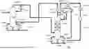


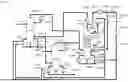
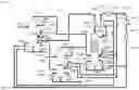
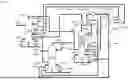
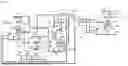


Sources:
- United States Patent and Trademark Office - verify current appl. status at the USPTO↗
Recent applications in this class:
- » 20260001826 2026-01-01
METHOD FOR PRODUCING AN ALKALI METAL ALKOXIDE - » 20240308942 2024-09-19
PROCESS FOR THE ENERGY-EFFICIENT PREPARATION OF ALKALI METAL ALCOHOLATES - » 20240025829 2024-01-25
INTEGRATED PROCESS FOR THE PARALLEL PRODUCTION OF ALKALI METAL METHOXIDES - » 20220340509 2022-10-27
Process for the energy-efficient production of alkali metal alkoxides - » 20220340508 2022-10-27
Process for the energy-efficient production of alkali metal alkoxides - » 20170066701 2017-03-09
METAL ALKOXIDE AND A PROCESS FOR ITS PREPARATION - » 20170022130 2017-01-26
METHOD FOR PRODUCING MAGNESIUM ALCOHOLATE - » 20160229773 2016-08-11
Method to synthesize lanthanide fluoride materials from lanthanide fluorinated alkoxides - » 20160009616 2016-01-14
Method for Producing a Water Soluble Menthol Compounds having Antibacterial, Anti-Inflammatory, and Bacteriostatic Effects - » 20120322958 2012-12-20
MIXED MAGNESUM DIALKOXIDE PARTICULATE, METHOD FOR SYNTHESIZING SAME, AND METHOD FOR USE THEREOF
Recent applications for this Assignee:
- » 20260129720 2026-05-07
CATALYTICALLY ACTIVE HEATING ELEMENTS, PRODUCTION AND USE THEREOF - » 20260109789 2026-04-23
DEVULCANIZED RUBBER, PROCESS FOR PRODUCING DEVULCANIZED RUBBER, AND USE THEREOF - » 20260109085 2026-04-23
MOLD RELEASE AGENT FOR POLYURETHANE ARTICLES - » 20260102441 2026-04-16
PROBIOTIC COMPOSITION FOR THE TREATMENT OF MALNUTRITION - » 20260102440 2026-04-16
PROBIOTIC STRAINS FOR THE TREATMENT OF IRRITABLE BOWEL SYNDROME AND FODMAP INTOLERANCE - » 20260102345 2026-04-16
POLYOXYALKYLENE-1,2-DIMYRISTOYL-GLYCEROL COMPOUNDS, WHEREIN THE POLYOXYALKYLENE IS A POLY(ETHYLENE OXIDE) HAVING C1 TO C3-ALKYLOXYMETHYL SIDE CHAINS - » 20260094680 2026-04-02
DIGITAL MONITORING OF PATHOGEN LOAD IN LIVESTOCK - » 20260085038 2026-03-26
PROCESS FOR OBTAINING MIXTURES CONTAINING METHIONINE AND POTASSIUM HYDROGENCARBONATE - » 20260083655 2026-03-26
COMPOSITIONS COMPRISING SOPHOROLIPIDS AND LACTIC ACID - » 20260071261 2026-03-12
METHOD OF ASSESSING PROTEIN PRODUCTION IN CHO CELLS