HUMIDIFIER AND METHOD FOR CONTROLLING THE SAME
US20260132953A1
2026-05-14
19/357,827
2025-10-14
Smart Summary: A humidifier has a water tank that holds water and a heating source to warm it up. It includes a temperature sensor outside the tank to measure the water's temperature and a weight sensor to check how much water is inside. Before starting normal operation, the device recognizes the initial temperature and uses the weight information to decide which preheating mode to use. There are two preheating modes: one that heats the water more strongly and another that heats it less. This helps ensure the humidifier works efficiently and safely. 🚀 TL;DR
Abstract:
A humidifier comprises: a water tank configured to store water; a heating source configured to heat the water stored in the water tank; a temperature sensor disposed outside the water tank and configured to detect a temperature of the water tank; a weight sensor configured to detect a weight of the water tank; and a controller configured to, before entering a normal humidification mode, recognize an initial temperature based on temperature information detected by the temperature sensor, and configured to control execution of at least one of a first preheating mode and a second preheating mode based on the recognized initial temperature and the weight detected by the weight sensor. The first preheating mode includes a mode configured to control output of the heating source to a first output. The second preheating mode includes a mode configured to control the output of the heating source to a second output less than the first output.
Inventors:
- Sanghoon LEE 59 🇰🇷 Suwon-si, South Korea
- Sungjune CHO 25 🇰🇷 Suwon-si, South Korea
- Joonhyoung KIM 13 🇰🇷 Suwon-si, South Korea
Applicant:
Interested in similar patents?
Get notified when new applications in this technology area are published.
Classification:
F24F11/80 » CPC main
Control or safety arrangements; Control systems characterised by their outputs; Constructional details thereof for controlling the temperature of the supplied air
F24F6/025 » CPC further
Air-humidification, e.g. cooling by humidification by evaporation of water in the air using electrical heating means
F24F11/48 » CPC further
Control or safety arrangements for purposes related to the operation of the system, e.g. for safety or monitoring prior to normal operation, e.g. pre-heating or pre-cooling
F24F11/61 » CPC further
Control or safety arrangements characterised by user interfaces or communication using timers
F24F11/64 » CPC further
Control or safety arrangements characterised by the type of control or by internal processing, e.g. using fuzzy logic, adaptive control or estimation of values; Electronic processing using pre-stored data
F24F11/66 » CPC further
Control or safety arrangements characterised by the type of control or by internal processing, e.g. using fuzzy logic, adaptive control or estimation of values; Electronic processing for selecting an operating mode Sleep mode
F24F11/88 » CPC further
Control or safety arrangements Electrical aspects, e.g. circuits
F24F11/89 » CPC further
Control or safety arrangements Arrangement or mounting of control or safety devices
F24F2006/008 » CPC further
Air-humidification, e.g. cooling by humidification Air-humidifier with water reservoir
F24F11/526 » CPC further
Control or safety arrangements characterised by user interfaces or communication; Indication arrangements, e.g. displays giving audible indications
F24F6/00 IPC
Air-humidification, e.g. cooling by humidification
F24F6/02 IPC
Air-humidification, e.g. cooling by humidification by evaporation of water in the air
Description
CROSS-REFERENCE TO RELATED APPLICATIONS
This application is a continuation of International Application No. PCT/KR2025/013956 designating the United States, filed on Sep. 9, 2025, in the Korean Intellectual Property Receiving Office and claiming priority to Korean Patent Application Nos. 10-2024-0162476, filed on Nov. 14, 2024, and 10-2025-0005566, filed on Jan. 14, 2025, in the Korean Intellectual Property Office, the disclosures of each of which are incorporated by reference herein in their entireties.
BACKGROUND
Field
The disclosure relates to a humidifier configured to heat water and configured to discharge moisture, which is generated by the heating, into air, and a control method thereof.
Description of Related Art
A humidifier is a device that increases or maintains humidity of indoor air.
The types of humidifiers may include heating type, ultrasonic type, and combination types that combine heating type and ultrasonic type, centrifugal spray type that blows water with centrifugal force and hits a screen to break the water into small particles and expels the particles, and filter vaporization type that evaporates water by passing air through a wet filter to generate moisture.
The heating type humidifier requires a long time of about 30 minutes for the water to boil, and has the problem of unstable humidification. In addition, the heating type humidifier may produce more humidification than necessary, and it is difficult to maintain the discharge temperature, and there is a problem that water must be replenished in a short period of time.
SUMMARY
Embodiments of the disclosure provide a humidifier capable of, before entering a normal humidification mode, controlling at least one of a first preheating mode and a second preheating mode based on at least one of a weight of water and an initial temperature detected by a temperature sensor, and a control method thereof.
According to an example embodiment, the present disclosure provides a humidifier including: a water tank configured to store water; a heating source configured to heat the water stored in the water tank; a temperature sensor disposed outside the water tank and configured to detect a temperature of the water tank; a weight sensor configured to detect a weight of the water tank; and a controller, comprising circuitry, configured to, before entering a normal humidification mode, recognize an initial temperature based on temperature information detected by the temperature sensor, and configured to control execution of at least one of a first preheating mode and a second preheating mode based on the recognized initial temperature and the weight detected by the weight sensor, wherein the first preheating mode includes a mode that controls output of the heating source to a first output, and the second preheating mode includes a mode that controls the output of the heating source to a second output less than the first output.
The humidifier may further include: a memory storing information on target temperatures matched to each initial temperature and each weight, wherein the controller of the humidifier may be configured to: recognize a target temperature corresponding to the recognized initial temperature and the weight detected by the weight sensor based on the information stored in the memory, control switching to the second preheating mode based on a temperature detected by the temperature sensor reaching the recognized target temperature during the execution of the first preheating mode, and control switching to the normal humidification mode based on an execution time of the second preheating mode reaching a reference operation time.
The controller of the humidifier may be configured to: control the execution of the first preheating mode and the second preheating mode based on the initial temperature being less than a reference temperature, and control the execution of the second preheating mode based on the initial temperature being greater than or equal to the reference temperature.
The humidifier may further include a memory storing information on target temperatures matched to each initial temperature and each weight. The controller of the humidifier may be configured to: recognize a target temperature corresponding to the recognized initial temperature and the weight detected by the weight sensor based on the information stored in the memory in response to the initial temperature being less than the reference temperature, control switching to the second preheating mode based on the temperature detected by the temperature sensor reaching the recognized target temperature during the execution of the first preheating mode, and control the execution of the second preheating mode for a reference operation time.
The humidifier may further include a memory storing information on target operation times for each weight. The controller of the humidifier may be configured to: recognize a target operation time corresponding to a weight detected by the weight sensor based on the information stored in the memory in response to the initial temperature being greater than or equal to a reference temperature, and control the execution of the second preheating mode for the recognized target operation time.
The memory of the humidifier may store information on target operation times matched to each weight and each initial temperature. The controller of the humidifier may be configured to: recognize a target operation time corresponding to a weight detected by the weight sensor and the recognized initial temperature based on the information stored in the memory in response to the initial temperature being greater than or equal to a reference temperature, and control the execution of the second preheating mode for the recognized target operation time.
The humidifier may further include a blower configured to move steam generated in the water tank. The controller of the humidifier may be configured to control a rotation speed of the blower during the execution of the first preheating mode, the second preheating mode, and the normal humidification mode.
The controller of the humidifier may be configured to: recognize a change in weight based on weight information detected by the weight sensor, recognize a change in temperature for a temperature detected by the temperature sensor based on temperature information detected by the temperature sensor, and control the execution of at least one of the first and second preheating modes based on changes in the weight, the temperature, and power on/off.
The controller of the humidifier may be configured to: control the execution of the first preheating mode based on the initial temperature being less than the reference temperature, and control the execution of the second preheating mode based on the initial temperature being greater than or equal to the reference temperature.
The humidifier may further include a memory storing information on target operation times matched to each initial temperature and each weight. The controller of the humidifier may be configured to: recognize a target operation time corresponding to the recognized initial temperature and a weight detected by the weight sensor based on the information stored in the memory in response to the initial temperature being less than a reference temperature, control the execution of the first preheating mode for the recognized target operation time, and control execution of the normal humidification mode in response to the completion of the first preheating mode,
The controller of the humidifier may be configured to: control the execution of the second preheating mode based on the initial temperature being greater than or equal to the reference temperature, and control the execution of the normal humidification mode in response to the completion of the second preheating mode.
The humidifier may further include a blower configured to move steam generated in the water tank. The controller of the humidifier may be configured to control rotation of the blower during the execution of the first preheating mode, the second preheating mode, and the normal humidification mode.
According to an example embodiment of the present disclosure a method of operating a humidifier is provided, including: recognizing an initial temperature of a water tank based on temperature information detected by a temperature sensor; executing at least one of a first preheating mode and a second preheating mode based on the recognized initial temperature and a weight detected by a weight sensor; and executing a normal humidification mode based on the completion of the first preheating mode or the second preheating mode, wherein the first preheating mode is a mode that controls output of a heating source configured to apply heat to the water tank, to a first output, and the second preheating mode is a mode that controls the output of the heating source to a second output less than the first output.
Executing at least one of the first preheating mode and the second preheating mode may include: recognizing a target temperature corresponding to the recognized initial temperature and the weight detected by the weight sensor based on the information stored in a memory, controlling switching to the second preheating mode based on a temperature detected by the temperature sensor reaching the recognized target temperature during the execution of the first preheating mode, and controlling the execution of the second preheating mode for a reference operation time.
Executing at least one of the first preheating mode and the second preheating mode may include: controlling the execution of the first preheating mode and the second preheating mode based on the initial temperature being less than a reference temperature, and controlling the execution of the second preheating mode based on the initial temperature being greater than or equal to the reference temperature.
Controlling the execution of the first preheating mode and the second preheating mode may include: recognizing a target temperature corresponding to the recognized initial temperature and the weight detected by the weight sensor based on information stored in a memory; controlling switching to the second preheating mode based on a temperature detected by the temperature sensor reaching the recognized target temperature during the execution of the first preheating mode, and controlling the execution of the second preheating mode for a reference operation time.
Controlling the execution of the second preheating mode may include: recognizing a target operation time corresponding to a weight detected by the weight sensor based on information stored in a memory, and controlling the execution of the second preheating mode for the recognized target operation time.
Controlling the execution of the second preheating mode may include: recognizing a target operation time corresponding to a weight detected by the weight sensor and the recognized initial temperature based on information stored in a memory, and controlling the execution of the second preheating mode for the recognized target operation time.
Executing at least one of the first preheating mode and the second preheating mode may include: controlling the execution of the first preheating mode based on the initial temperature being less than a reference temperature, and controlling the execution of the second preheating mode based on the initial temperature being greater than or equal to the reference temperature.
Controlling the execution of the first preheating mode may include: recognizing a target operation time corresponding to the recognized initial temperature and a weight detected by the weight sensor based on information stored in a memory, and controlling the execution of the first preheating mode for the target operation time. Controlling the execution of the second preheating mode may include controlling the execution of the second preheating mode for a reference operation time.
It is possible to prevent and/or reduce water in a water tank from boiling over by controlling output of a heating source while executing a quick humidification mode before entering a normal humidification mode, thereby preventing and/or reducing water leakage and water contamination.
Further, it is possible to prevent and/or reduce over-operation of quick humidification by controlling output of a heating source from high output to low output while executing a quick humidification mode before entering a normal humidification mode. Accordingly, it is possible to prevent and/or reduce a rapid increase in an amount of humidity, thereby preventing and/or reducing condensed water from occurring around a discharge port.
Further, it is possible to prevent and/or reduce a temperature of a discharge port from rising due to a rapid increase in an amount of humidity. Accordingly, it is possible to protect a user from risk of burns.
Further, because steam is generated by heating water in a container disposed inside a water tank, it is possible to minimize and/or reduce a heating time of water, and to minimize and/or reduce a time of noise generation caused by the heating of the water. Further, it is possible to reduce power consumed for heating the water.
Further, it is possible to improve the marketability of humidifiers and further secure the competitiveness of humidifiers.
BRIEF DESCRIPTION OF THE DRAWINGS
The above and other aspects, features and advantages of certain embodiments of the present disclosure will be more apparent from the following detailed description, taken in conjunction with the accompanying drawings, in which:
FIG. 1 is a perspective view of a humidifier according to various embodiments;
FIG. 2 is a cross-sectional view of the humidifier according to various embodiments;
FIG. 3 is an exploded perspective view of the humidifier according to various embodiments;
FIG. 4 is an exploded perspective view of a water tank assembly of the humidifier according to various embodiments;
FIG. 5 is a diagram illustrating a water tank of the humidifier according to various embodiments
FIG. 6 is a diagram illustrating an enlarged view of a region A illustrated in FIG. 2 according to various embodiments;
FIG. 7 is a perspective view illustrating an example of a frame of the humidifier according to various embodiments;
FIG. 8 is a diagram illustrating an example of arrangement of a first case and a weight sensor of the humidifier according to various embodiments;
FIG. 9 is a circuit diagram illustrating an example of weight detection of the weight sensor of the humidifier according to various embodiments;
FIG. 10 is a cross-sectional view illustrating an example of a lower portion of a housing of the humidifier according to various embodiments;
FIG. 11 is an exploded perspective view illustrating an example of arrangement of a heating source and a temperature sensor of the humidifier according to various embodiments;
FIG. 12 is a block diagram illustrating an example configuration of the humidifier according to various embodiments;
FIG. 13 is a table illustrating information on target temperatures of the temperature sensor and target operation times matched to each weight of water stored in the water tank of the humidifier and each initial temperature detected by the temperature sensor according to various embodiments;
FIG. 14 is a flowchart illustrating an example operation of the humidifier according to various embodiments;
FIG. 15 is a block diagram illustrating an example configuration of a humidifier according to various embodiments;
FIG. 16 is a table illustrating information on target temperatures of a temperature sensor for each water weight range of the humidifier according to various embodiments;
FIG. 17 is a table illustrating information on target operation times for each water weight range of the humidifier according to various embodiments;
FIGS. 18 and 19 are tables illustrating control information for each control target of a quick humidification mode in each normal humidification mode of the humidifier according to various embodiments;
FIG. 20 is a table illustrating information on target operation times matched to each water weight range and each initial temperature range of the temperature sensor of the humidifier according to various embodiments;
FIG. 21 is a flowchart illustrating an example operation of the humidifier according to various embodiments;
FIG. 22 is a block diagram illustrating an example configuration of a humidifier according to various embodiments;
FIG. 23 is a table illustrating information on target operation times matched to each initial temperature range and water weight range of a temperature sensor of the humidifier according to various embodiments; and
FIG. 24 is a flowchart illustrating an example operation of the humidifier according to various embodiments.
DETAILED DESCRIPTION
Various example embodiments and the terms used therein are not intended to limit the technology disclosed herein to specific forms, and the disclosure should be understood to include various modifications, equivalents, and/or alternatives of the various embodiments.
In describing the drawings, similar reference numerals may be used to designate similar elements.
A singular expression may include a plural expression unless otherwise indicated herein or clearly contradicted by context.
The expressions “A or B,” “at least one of A or/and B,” or “one or more of A or/and B,” A, B or C,” “at least one of A, B or/and C,” or “one or more of A, B or/and C,” and the like used herein may include any and all combinations of one or more of the associated listed items.
The terms “a first”, “a second”, “the first”, “the second”, etc., may simply be used to distinguish an element from other elements, but is not limited to another aspect (importance or order) of elements.
When an element (e.g., a first element) is referred to as being “(functionally or communicatively) coupled,” or “connected” to another element (e.g., a second element), the first element may be connected to the second element, directly (e.g., wired), wirelessly, or through a third element.
The terms “including”, “having”, and the like are used to specify features, numbers, steps, operations, elements, components, or combinations thereof, but do not preclude the presence or addition of one or more of the features, elements, steps, operations, elements, components, or combinations thereof.
When an element is said to be “connected”, “coupled”, “supported” or “contacted” with another element, this includes not only when elements are directly connected, coupled, supported or contacted, but also when elements are indirectly connected, coupled, supported or contacted through a third element.
Throughout the disclosure, when an element is “on” another element, this includes not only when the element is in contact with the other element, but also when there is another element between the two elements.
The term of “and/or” includes a plurality of combinations of relevant items or any one item among a plurality of relevant items.
A reference number may be used for the convenience of the description but is not intended to illustrate the order of each step or operation. The each step or operation may be implemented in the order different from the illustrated order unless the context clearly indicates otherwise.
Hereinafter various example embodiments of the present disclosure will be described in greater detail with reference to the accompanying drawings
FIG. 1 is a perspective view of a humidifier according to various embodiment, which will be described in greater detail below with reference to FIGS. 2 to 11.
FIG. 2 is a cross-sectional view of the humidifier according to various embodiments, FIG. 3 is an exploded perspective view of the humidifier according to various embodiments, FIG. 4 is an exploded perspective view of a water tank assembly of the humidifier according to various embodiments, FIG. 5 is a diagram illustrating a water tank of the humidifier according to various embodiments, and FIG. 6 is an enlarged cross-sectional view of a region A illustrated in FIG. 2 according to various embodiments.
FIG. 7 is a perspective view illustrating an example of a frame of the humidifier according to various embodiments, FIG. 8 is a diagram illustrating an example of arrangement of a first case and a weight sensor of the humidifier according to various embodiments, FIG. 9 is a circuit diagram illustrating an example of weight detection of the weight sensor of the humidifier according to various embodiments, FIG. 10 is a cross-sectional view illustrating an example of a lower portion of a housing of the humidifier according to various embodiments, and FIG. 11 is an exploded perspective view illustrating an example of arrangement of a heating source and a temperature sensor of the humidifier according to various embodiments.
A humidifier according to the disclosure may be a heating type humidifier that increases or maintains humidity of indoor air by heating water and discharging steam generated by the heating into the air.
The humidifier according to the disclosure may further include an air purification function that draws in indoor air, filters out harmful bacteria, dust, odors, fine dust, and the like contained in the drawn indoor air, and discharges the filtered air into the room, in addition to a humidification function that increases or maintains the humidity of indoor air. For example, the humidifier of the present embodiment may be provided integrally with an air purifier.
An example embodiment will be described with respect to an example in which the humidifier includes an air purifier, but the present disclosure may also be implemented with an example in which only the humidifier is provided.
As illustrated in FIG. 1, a humidifier 1 may include a main body 10. The main body 10 may form an exterior of the humidifier 1. For example, the main body 10 may be provided in a substantially box shape. The main body 10 may also be provided in a cylindrical shape, and the shape of the main body is not limited thereto.
The main body 10 may include a plurality of panels. The exterior of the humidifier 1 may be formed by the plurality of panels.
The plurality of panels may include a first panel 11 provided on an upper side of the main body 10, a second panel 12 provided on a lower side of the main body 10, and a third panel 13 provided between the first panel 11 and the second panel 12.
A user interface 100 may be provided on the first panel 11 of the main body 10. For example, the user interface 100 may include a touch screen 110, a lamp 130, and a speaker. The user interface 100 may receive an input (e.g., a user input), and output operation information of the humidifier 1 to a user.
The user interface 100 may include an inputter and a display portion.
The user interface 100 may include a touch screen 110 in which the inputter and the display portion are integrally provided. The touch screen 110 may be provided on the first panel 11.
The inputter and the display portion of the user interface 100 may also be provided separately.
The inputter may include hardware devices such as various buttons, switches, pedals, keyboards, mouses, track-balls, various levers, handles, sticks, microphones, and the like for user input.
The inputter may include a Graphical User Interface (GUI), that is, a software device, such as a touch pad, for user input.
The display portion may be provided as a digital light processing (DLP) panel, a plasma display panel, a liquid crystal display (LCD) panel, an electroluminescence (EL) panel, an electrophoretic display (EPD) panel, an electrochromic display (ECD) panel, a light emitting diode (LED) panel, or an organic light emitting diode (OLED) panel, but is not limited thereto.
The lamp 130 may be provided on the first panel 11 of the main body 10. The lamp 130 may be provided to protrude from a surface of the first panel 11 of the main body 10.
The lamp 130 may be provided in a size corresponding to an edge of a second cover 380. The lamp 130 protruding from the surface of the first panel 11 may receive the second cover 380.
The lamp 130 may be provided on an opening side of a receiving space 10a of the main body 10.
The lamp 130 may be provided in a ring shape, but the shape of the lamp is not limited thereto.
A single lamp 130 may be provided or a plurality of lamps 130 may be provided.
When the plurality of lamps is provided, the plurality of lamps may be disposed adjacent to each other. The plurality of lamps provided adjacent to each other may also be coupled to form a ring shape.
The lamp 130 may emit light of a plurality of colors. For example, the plurality of colors may include red, yellow, orange, green, and blue.
The lamp 130 may be turned on and off, and may perform flashing by repeating turning on and off at regular time intervals.
The touch screen 110 and the lamp 130 may output output-information corresponding to at least one of a temperature of water stored in a water tank, an amount of water stored in the water tank, and operation information of operation mode of the humidifier.
The operation mode of the humidifier may include a humidification mode and a cleaning mode.
The speaker may output sound corresponding to at least one of the temperature of water stored in the water tank, the amount of water stored in the water tank, and the operation information of the operation mode of the humidifier.
The third panel 13 may be provided integrally to surround a circumferential surface of the main body 10.
The third panel 13 may be provided with a plurality of detachable blower panels. The plurality of blower panels may be provided to form the circumferential surface of the main body 10 by being coupled to each other.
The third panel 13 may be provided with at least one inlet for introducing indoor air, and at least one outlet for discharging air inside the main body 10 into the indoor space.
The at least one inlet and the at least one outlet may be arranged in a direction perpendicular to an up and down direction (Z direction) of the third panel 13.
The inlet provided on the third panel 13 may be provided at a lower side of the outlet provided in the third panel 13. For example, the inlet may be provided in a region adjacent to the second panel among the regions of the third panel. The outlet may be provided in a central region with respect to the up and down direction, among the regions of the third panel. For example, the central region of the third panel may include a middle region among the regions between the first panel 11 and the second panel 12.
As illustrated in FIG. 2, an air cleaning portion (AC) provided in the humidifier 1 may include a blower 20, and a filter 30.
The blower 20 may be disposed in the main body 10. The blower 20 may be positioned lower than the inlet with respect to a direction of air flow from the inlet of the third panel to the outlet of the third panel. The blower 20 may be positioned higher than the outlet with respect to the direction of air flow from the inlet to the outlet. That is, the blower 20 may be positioned between the inlet and the outlet.
The blower 20 may generate blowing force. The blower 20 may move air. The blower 20 may rotate to generate an air flow, which flows inside the main body 10, thereby forcing air to flow.
The blower 20 may allow indoor air to flow into an inside of the main body 10 and allow air inside the main body 10 to be discharged to an outside of the main body 10.
The blower 20 may allow air to move in a first direction D1. For example, the blower 20 may allow air to move upward. The first direction D1 may be a blowing direction of the blower 20. The first direction D1 may be a flow direction of air moved by the blower 20. The first direction D1 may be a flow direction of air from the inlet of the third panel to the outlet of the third panel.
The blower 20 may include a fan. The fan may include blades, and a fan motor configured to rotate the blades.
The air cleaning portion (AC) may further include an air guide 25. The air guide 25 may be disposed inside the main body 10. The air guide 25 may be disposed on a lower side of the blower 20. The air guide 25 may guide air, which flows into the main body 10 through the inlet of the third panel, to the blower 20.
The filter 30 of the air cleaning portion may be disposed inside the main body 10 and may filter the introduced air.
The filter 30 may collect aerosols in the air.
The filter 30 may include an electrostatic precipitator configured to collect dust particles using electrostatic force of an electric field.
The filter 30 may be disposed between the inlet and the outlet to allow air, which is introduced through the inlet of the third panel 13, to pass therethrough. For example, the filter 30 may be disposed below the blower 20. The filter 30 may filter air that is introduced into the main body 10 through the inlet. The air filtered by the filter 30 may be discharged to the outside of the main body 10 through the outlet.
The filter 30 may include a dust collection filter such as a High Efficiency Particulate Air (HEPA) filter, and a deodorizing and harmful substance adsorption filter, such as an activated carbon filter. The filter 30 may remove odorous substances in the air and may sterilize the air by decomposing organic substances in the air.
The air cleaning portion (AC) of the humidifier 1 may introduce and/or discharge air in all directions to allow air circulation inside the main body 10 to be performed smoothly. Therefore, the air cleaning portion (AC) of the humidifier 1 may obtain high dust collection efficiency.
The humidifier 1 may perform an air purification function in a lower region of the main body 10 and a humidification function in an upper region of the main body 10.
The humidifier 1 may heat water in the upper region of the main body 10 to generate steam, and may discharge the generated steam to the outside of the main body 10 through a steam discharge port 14.
The steam discharge port 14 may be provided on one surface of the main body 10. For example, the steam discharge port 14 may be provided on the first panel 11 of the main body 10. The steam discharge port 14 may be provided on the inner side of the first panel 11.
As illustrated in FIG. 3, the humidifier 1 may include a housing 200 provided in the upper region of the main body 10, and a water tank assembly 300 provided inside the housing 200.
The housing 200 of the humidifier may be provided inside the main body 10.
The housing 200 of the humidifier may include the receiving space 10a for receiving the water tank assembly 300. The receiving space 10a may be provided by being recessed on one surface of the main body 10. For example, the receiving space 10a may be provided by being recessed on one surface adjacent to the first panel 11 of the main body 10.
The steam discharge port 14 may be provided around an edge of the receiving space 10a.
As illustrated in FIG. 4, the water tank assembly 300 may include a water tank 310, a water tank case 320 provided to receive the water tank 310, a coupling member 330 provided on an upper side of the water tank case 320 and coupled to an outer circumferential surface of the water tank case 320, and a valve 340, a guide member 350, a water distribution portion 360, a first cover 370, and the second cover 380 provided on the upper side of the water tank 310.
The water tank 310 may include a first water tank 311, and a second water tank 312 provided inside the first water tank 311.
The first water tank 311 may be an external tank and may store water.
An upper portion of the first water tank 311 may be opened, and the first water tank 311 may receive water while the first water tank 311 is in an open state.
The first water tank 311 may be provided in a substantially cylindrical shape, but the shape of the first water tank is not limited thereto.
The first water tank 311 may receive heat from the second water tank 312. Accordingly, a temperature of the water in the first water tank 311 may be increased.
The first water tank 311 may be provided with a plurality of layers. At least one layer of the first water tank 311 may be formed of STS304, which is resistant to heat and corrosion, among stainless steel materials. Another layer of the first water tank 311 may be formed of aluminum that is a metal with good thermal conductivity. Another layer of the first water tank 311 may be formed of STS430 material, which has excellent heating properties against a magnetic field, among stainless steel materials.
The second water tank 312 may be provided inside the first water tank 311. That is, the second water tank 312 may be an internal tank.
The second water tank 312 may store water and receive water from the first water tank 311.
The second water tank 312 may be provided adjacent to a heating source. The water in the second water tank may be heated by the heating source, changed into steam, and discharged to the outside.
The second water tank 312 may be formed of a metal material with good corrosion resistance. For example, the second water tank 312 may be formed of stainless steel. The material of the second water tank 312 is not limited to metal. For example, the second water tank 312 may be formed of heat-resistant plastic or ceramic materials.
The configuration of the water tank 310 will be described in greater detail below.
The water tank case 320 may receive the water tank 310.
The water tank case 320 may surround an outer wall of the water tank 310.
The water tank case 320 may have a shape corresponding to the water tank 310. For example, the water tank case 320 may be provided in a substantially cylindrical shape.
The water tank case 320 may be formed in a cylindrical shape and may be arranged to surround the water tank 310. An upper portion and a lower portion of the water tank case 320 may be opened. The water tank case 320 may be formed of a plastic material rather than a metal material.
The coupling member 330 may be coupled to the water tank case 320. The coupling member 330 may be provided on the upper side of the water tank case 320.
The coupling member 330 may surround an outer surface of the guide member 350.
An air discharge hole 331 through which water passes may be formed on an outer circumferential surface of the coupling member 330. At least a portion of the air flowing toward the steam discharge port 14 may pass through the air discharge hole 331 and then be discharged to the outside through the first cover 370.
A plurality of air discharge holes 331 may be provided. The plurality of air discharge holes 331 may be arranged along an edge of the outer circumferential surface of the coupling member 330.
A sealing member 332 may be provided in the coupling member 330. The sealing member 332 may seal between an edge of the upper portion of the water tank 310 and an edge of a first guide portion 351.
The valve 340 may be mounted on an upper portion of the second water tank 312. The valve 340 may be mounted on a lower surface of the first guide portion 351. That is, the valve 340 may be disposed between the second water tank 312 and the first guide portion 351.
The valve 340 may allow a flow hole 351a of the first guide portion 351 to communicate with the second water tank 312. Steam generated in the second water tank 312 may pass through the inside of the valve 340 and flow into an outer space of the second water tank 312.
The guide member 350 may be provided on the upper side of the water tank 310.
The guide member 350 may be disposed between the water tank 310 and the first cover 370.
The guide member 350 may guide water to the first water tank 311 and guide steam generated inside the second water tank 312 to the outside.
The guide member 350 may include the first guide portion 351, and a second guide portion 352.
The first guide portion 351 may cover an open upper surface of the water tank 310. The first guide portion 351 may define a space of the first water tank 311 and a space of the second water tank 312.
The first guide portion 351 may include the flow hole 351a. The flow hole 351a may be opened in the up and down direction. The flow hole 351a may be provided approximately at a center portion of the first guide portion 351. The flow hole 351a may allow steam generated in the second water tank 312 to flow to the outer space.
The first guide section 351 may include a first water supply hole 351b. The first water supply hole 351b may be opened in the up and down direction. One or more first water supply holes 351b may be provided.
The first water supply hole 351b may be provided at a position corresponding to the upper side of the first water tank 311. The supplied water may flow from the outer space of the water tank 310 to the first water tank 311 through the first water supply hole 351b.
The second guide portion 352 may be disposed on the upper side of the first and second tanks 311 and 312. Particularly, the second guide portion 352 may be disposed on an upper side of the first guide portion 351.
The second guide portion 352 and the first guide portion 351 may be spaced apart from each other. Steam and/or air may flow through a space between the second guide portion 352 and the first guide portion 351. For example, the second guide portion 352 may form a flow path together with the first guide portion 351.
The second guide portion 352 may include a second water supply hole 352a. The second water supply hole 352a may be opened in the up and down direction. The second water supply hole 352a may be provided on an upper side of the second water tank 312. The second water supply hole 352a may be connected to the first water supply hole 351b. One or more second water supply holes 352a may be provided.
Water may flow from the outer space of the first water tank 311 to the inner space of the first water tank 311 through the first water supply hole 351b and the second water supply hole 352a.
Each of the plurality of second water supply holes 352a may be provided to correspond to each of the plurality of first water supply holes 351b.
The second guide portion 352 may include a steam discharge hole 352b. The steam discharge hole 352b may be provided at an edge of the second guide portion 352. The edge of the second guide portion 352 may come into contact with an edge of the first guide portion 351, and the steam discharge hole 352b may form the steam discharge hole 352b together with the edge of the first guide portion 351.
One or more steam discharge holes 352b may be provided.
The guide member 350 may include a sealing member 353. The sealing member 353 may seal between the first water supply hole 351b and the second water supply hole 352a. One or more sealing members 353 may be provided.
The water distribution portion 360 may be disposed on an upper side of the second guide portion 352. The water distribution portion 360 may be disposed on the lower side of the first cover 370. For example, the water distribution portion 360 may be disposed between the second guide portion 352 and the first cover 370.
The water distribution portion 360 may be provided in such a way that a central portion thereof is the highest and an edge portion is the lowest. For example, the water distribution portion 360 may be provided in a convex disc shape.
The water distribution portion 360 may guide water, which is supplied to the center of the water distribution portion 360, to a radial direction of the water distribution portion 360. In addition, the water guided by the water distribution portion 360 may be uniformly spread to an upper surface of the second guide portion 352.
Water supplied to the water distribution portion 360 may flow into the first water tank 311 through the first and second water supply holes 351b and 352a of the guide member 350.
The first cover 370 may cover the upper side of the guide member 350. The first cover 370 may cover the upper side of the water tank case 320. The first cover 370 may cover the upper side of the coupling member 330. The first cover 370 may be provided on the inner side of the steam discharge port 14.
The first cover 370 may include a handle member 371 that may be gripped by a user.
The first cover 370 may include a cover opening 372. The cover opening 372 may be formed on the inside of the first cover 370. Water supplied from the outside may flow into the water tank 310 through the cover opening 372. That is, a user can supply water to the water tank 310 by pouring water into the cover opening 372.
The first cover 370 may include a steam discharge port 373. The steam discharge port 373 may be provided to discharge steam generated in the second water tank 312.
The steam discharge port 373 may be provided at an edge of the first cover 370. The steam discharge port 373 may be opened in the up and down direction.
The first cover 370 may include a discharge guide 374. The discharge guide 374 may be provided on an upper side of the steam discharge port 373.
The discharge guide 374 may be provided to guide steam and/or air discharged from the steam discharge port 373. The discharge guide 374 may form a flow path through which steam and/or air discharged from the steam discharge port 373 pass.
The second cover 380 may be disposed above the first cover 370.
The second cover 380 may prevent and/or block the first cover 370 from being exposed to the outside.
The second cover 380 may be provided inside the lamp 130.
As illustrated in FIG. 5, a lower surface of the first water tank 311 of the water tank 310 may include a protrusion 311a provided to come into contact with the water tank case 320, and a recessed portion 311b recessed from the outside to the inside of the water tank 310 and provided to allow a temperature sensor 160 to come into contact therewith.
The protrusion 311a of the first water tank 311 may be mounted on the water tank case 320.
The recessed portion 311b of the first water tank 311 may be provided to correspond to an induction heating coil 240.
The lower surface of the first water tank 311 of the water tank 310 may be a lower surface of the second water tank 312 of the water tank 310. The lower surface of the first water tank 311 of the water tank 310 may be a lower surface of the water tank 310.
The second water tank 312 may be formed in an overall triangular flask shape.
The second water tank 312 may include a seating member 312a provided adjacent to the protrusion 311a, an inclined member 312b connected to the seating member 312a, and a vertical member 312c connected to the inclined member 312b.
The seating member 312a of the second water tank 312 may be provided along the protrusion 311a. The seating member 312a of the second water tank 312 may be provided to surround the recessed portion 311b of the first water tank 311. The seating member 312a of the second water tank 312 may be provided to receive the recessed portion 311b of the first water tank 311.
The seating member 312a of the second water tank 312 may be provided at a position corresponding to the heating source 240 and may be provided to correspond to the shape of the heating source 240.
When the heating source 240 is circular, a diameter of the seating member 312a of the second water tank 312 may be formed to be equal to a diameter of the heating source 240 or larger than the diameter of the heating source 240.
A fluid in a heating region S1 inside the seating member 312a of the second water tank 312 and a fluid in a storage region S2 outside the seating member 312a of the second water tank 312 may be separated without freely mixing with each other. The storage region outside the seating member 312a of the second water tank 312 may be a storage region of the first water tank 311.
However, the heating region S1 inside the seating member 312a of the second water tank 312 and the storage region S2 outside the seating member 312a of the second water tank 312 may be not completely sealed from each other. When a water level inside the seating member 312a of the second water tank 312 is less than a water level outside the seating member 312a of the second water tank 312, the water may flow from the outside of the seating member 312a of the second water tank 312 to the inside of the seating member 312a of the second water tank 312 through a flow hole, which is disposed between the lower surface of the water tank 310 and the seating member 312a, due to the water pressure difference.
The inclined member 312b of the second water tank 312 may be provided to be inclined relative to the seating member 312a. The inclined member 312b of the second water tank 312 may be provided to be inclined toward the center of the second water tank 312. The inclined member 312b of the second water tank 312 may be provided to have an internal cross-sectional area that decreases from a lower side to an upper side of the second water tank. The inclined member 312b of the second water tank 312 may form a reference angle with respect to the vertical direction. For example, the reference angle may include angles greater than 45°.
The inclined member 312b of the second water tank 312 may be provided to cover the heating region S1, which is heated by the heating source 240, in the recessed portion 311b of the first water tank 311. Accordingly, an amount of heat generated by the heating source 240 may be concentratedly transferred to an inner space of the inclined member 312b of the second water tank 312. Therefore, steam may be generated within a short period of time from a time of an initial operation of the heating source 240.
Because a volume of water contained in the inclined member 312b of the second water tank 312 is very small, rapid humidification, in which a time required for the initial water to begin heating and generate steam is greatly reduced, is possible.
By allowing heat generation to occur in a wide region of the lower surface of the second tank of the water tank 310 depending on the size of the heating source 240, a heat generation density, which is an amount of heat generation per unit area, may be reduced. Accordingly, when the heating source 240 heats the lower surface of the second water tank of the water tank 310 for humidification, noise generated during the water heating process may be reduced due to the low heat generation density.
The vertical member 312c of the second water tank 312 may be provided vertically in the vertical direction from the inclined member 312b of the second water tank 312.
The vertical member 312c of the second water tank 312 may be a region in which steam is generated as the water is heated.
The vertical member 312c of the second water tank 312 may guide the generated steam to be discharged to the outside. The vertical member 312c of the second water tank 312 may have a height higher than a maximum water level of the first water tank of the water tank 110.
The vertical member 312c of the second water tank 312 may be formed in a long cylindrical shape.
When the heating source 240 is circular, a diameter L of the vertical member 312c of the second water tank 312 may be formed to be equal to a diameter of the heating source 240 or less than the diameter of the heating source 240.
The vertical member 312c of the second water tank 312 may include a cylindrical side surface parallel to the vertical direction. In this case, an angle formed between an inner surface of the vertical member 312c of the second water tank 312 and the vertical direction may be 0° (zero).
When the diameter L of the vertical member 312c of the second water tank 312 is small, a volume of the vertical member 312c may be reduced. Accordingly, a time required for steam to be generated from the initial operation time of the heating source 240 may be reduced.
As illustrated in FIG. 6, the housing 200 may include a first case 210, a second case 220, and a frame 230.
The first case 210 may be provided in the main body 10. The first case 210 may be provided in the receiving space 10a of the main body 10.
The first case 210 may be provided so as to be separable from the main body 10. The first case 210 may be provided so as to be separable from the receiving space 10a of the main body 10.
The first case 210 may receive the water tank assembly 300.
The first cover 370 of the water tank assembly 300 may be mounted to the first case 210.
When the water tank assembly 300 is received in the receiving space 10a, the first case 210 may be provided spaced apart from the water tank case 320 of the water tank assembly 300 by the first cover 370 of the water tank assembly 300.
The second case 220 may be provided in the main body 10. The second case 220 may be provided in the receiving space 10a of the main body 10. The second case 220 may be provided at the lower portion of the main body 10. The second case 220 may be provided so as to be separable from the main body 10.
The second case 220 may be provided on the lower side of the housing 200. The second case 220 may be provided on the lower side of the first external case 210.
The second case 220 may receive the water tank assembly 300. The second case 220 may be adjacent to the lower portion of the water tank case 320 of the water tank assembly 300.
The second case 220 may be formed of a material having relatively high magnetic field permeability and heat resistance. For example, the second case 220 may be formed of a material such as heat-resistant glass, ceramic, and heat-resistant plastic.
The first and second cases 210 and 220 may be separated from the housing 200 together with the water tank assembly 300. The first and second cases 210 and 220 may also be received within the housing 200 together with the water tank assembly 300.
The frame 230 may be provided inside the main body 10 and may be provided on the lower side of the first panel 11.
The frame 230 may be provided inside the housing 200, but may be provided corresponding to an edge of the housing 200.
The frame 230 may support the first case 210. The upper portion of the first case 210 may be mounted on the frame 230.
The frame 230 may be provided in the same shape as the upper shape of the first case 210. The frame 230 may be provided in a ring shape.
As illustrated in FIG. 7, one or more weight sensors 150: R1, R2, R3, and R4 may be provided on the frame 230. A humidifier provided with four weight sensors is described.
A plurality of weight sensors 150 may be provided on the lower side of the frame 230 and spaced apart at a predetermined interval.
The plurality of weight sensors 150 may be provided in a ring-shaped frame 230, and may be provided toward the inside of the frame 230.
The first case 210 may come into contact with and be mounted on the plurality of weight sensors 150.
As illustrated in FIG. 8, each of the plurality of weight sensors 150 may come into contact with a protruding member 211 that protrudes from the outside of the first case 210 but protrudes in the downward direction of the first case 210. That is, when the first case 210 is mounted on the plurality of weight sensors 150, the protruding member 211 of the first case 210 may come into contact with each of the plurality of weight sensors 150.
The plurality of weight sensors 150 may detect a weight of the first case 210 mounted on the plurality of weight sensors 150 provided on the frame 230.
Because the water tank assembly 300 is mounted on the first case 210, a weight detected by the plurality of weight sensors 150 may be the sum of a weight of the first case 210 and a weight of the water tank assembly 300.
When water is stored in the water tank 310 of the water tank assembly 300, a weight detected by the plurality of weight sensors 150 may be the sum of a weight of the first case 210, a weight of the water tank assembly 300, and a weight of the water.
The weight detected by the plurality of weight sensors 150 may be used to detect the weight of water stored in the water tank 310. The weight of water may include an amount of water.
An accuracy of detecting the amount of water may be improved by detecting the amount of water stored in the water tank 310 using the plurality of weight sensors 150.
A method of detecting a weight using the plurality of weight sensors 150 is described with reference to FIG. 9.
When unloaded, a weight detected by the plurality of weight sensors is as follows.
The unloaded may refer, for example, to the water tank assembly provided with the water tank in which no water is stored, and the first case. A weight detected at the unloaded time may be the sum of a weight of the first case and a weight of the water tank assembly.
V A B = ( R 1 / ( R 1 + R 2 ) ) * V , V A D = ( R 4 / ( R 3 + R 4 ) ) * V , E = V AB - V AD = ( ( R 1 R 3 - R 2 R 4 ) / ( R 1 + R 2 ) ( R 3 + R 4 ) ) * V
When loaded, a weight detected by the plurality of weight sensors may be as follows.
The load may be water stored in the water tank of the water tank assembly. A weight detected at the time of load may include a weight of water stored in the water tank.
Δ E = ( S 1 / S 2 ) * V S 1 = ( R 1 + Δ R 1 ) * ( R 3 + Δ R 3 ) - ( R 2 + Δ R 2 ) * ( R 4 + ΔR 4 ) S 2 = ( R 1 + Δ R 1 + R 2 + Δ R 2 ) * ( R 3 + Δ R 3 + R 4 + Δ R 4 ) weight = E - Δ E
As illustrated in FIG. 10, the humidifier 1 may include the heating source 240.
The heating source 240 may be provided inside the housing 200. The heating source 240 may be provided on the lower side of the inside of the housing 200.
The heating source 240 may be provided at a position corresponding to the recessed portion 311b of the water tank 310.
The heating source 240 may be configured to heat water stored in the second water tank 312.
The heating source 240 may include a heater configured to generate heat and/or an induction heating coil configured to generate a magnetic field. A humidifier provided with an induction heating coil is described. The heating source and the induction heating coil may be indicated by the same drawing reference numeral “240”.
The induction heating coil may generate an induced current in at least a portion of the water tank 310 to heat the water. For example, when the induction heating coil operates, the recessed portion 311b of the water tank 310 may be heated, and the water inside the water tank 110 may be heated to generate steam. The heating of the recessed portion 311b of the water tank 310 may include heating the inside of the seating member and the inside of the inclined member of the second water tank 312.
As illustrated in FIGS. 10 and 11, the humidifier 1 may include the temperature sensor 160 configured to detect the temperature of water stored in the water tank 310 and a sensor case 250 provided to protect the temperature sensor 160.
The temperature sensor 160 may be provided adjacent to the water tank 310. The temperature sensor 160 may be provided adjacent to the second water tank 312.
The temperature sensor 160 may be provided inside the housing 200.
The temperature sensor 160 may be provided at the center of the lower side of the housing 200.
The temperature sensor 160 may be provided in the central region of the induction heating coil 240.
The temperature sensor 160 may be provided at a position corresponding to the second water tank 312 of the water tank 310.
When the water tank assembly 300 is received in the receiving space 10a of the housing 200, the temperature sensor 160 may come into contact with the second water tank 312 of the water tank 310. The temperature sensor 160 may detect the temperature of water stored in the second water tank 312 of the water tank 310.
The sensor case 250 may be provided inside the housing 200. The sensor case 250 may be provided at the center of the lower side of the housing 200.
The sensor case 250 may be provided in the central region of the induction heating coil 240. For example, a case receiving groove 241 may be provided in the central region of the induction heating coil 240. The case receiving groove 241 of the induction heating coil 240 may be provided at a position corresponding to the second water tank 312.
The sensor case 250 may be provided in the case receiving groove 241 provided in the induction heating coil 240. The sensor case 250 may be provided at a position corresponding to the second water tank 312 of the water tank 310.
The sensor case 250 may receive the temperature sensor 160.
The sensor case 250 may be formed of an elastic material.
When the water tank 310 of the water tank assembly 300 is received in the second case 220 and the sensor case 250 is pressed by the water tank 310, the sensor case 250 may be deformed in shape by elastic force. For example, when the sensor case 250 is pressed by the water tank 310, the shape of the sensor case 250 may be deformed in a direction in which the sensor case 250 is pressed downward.
FIG. 12 is a block diagram illustrating an example configuration of the humidifier according to various embodiments, and may be described with reference to FIG. 13.
FIG. 13 is a table illustrating information on target temperatures of the temperature sensor and target operation times matched to each weight of water stored in the water tank of the humidifier and each initial temperature detected by the temperature sensor according to various embodiments.
The humidifier 1 may include the blower 20, the user interface (e.g., including circuitry) 100, the weight sensor 150, the temperature sensor 160, a first controller (e.g., including circuitry) 170, and the heating source 240.
To distinguish a controller, the controller of the humidifier of an embodiment may be referred to as the first controller.
The blower 20 may be operated based on receiving an on-command of an air cleaning mode, and may be stopped based on receiving an off-command of the air cleaning mode.
Based on receiving the on-command of the air cleaning mode, the blower 20 may draw in air from an indoor space, and discharge air filtered within the main body into the indoor space.
The blower 20 may be operated based on receiving an execution command of a normal humidification mode, and may also be stopped based on a termination command of the normal humidification mode.
The blower 20 may discharge steam into the indoor space together with the drawn air based on receiving the execution command of the normal humidification mode. That is, the blower 20 may guide the movement of steam.
The blower 20 may rotate at a rotation speed corresponding to a control command of the first controller 170 and may rotate in a rotation direction corresponding to the control command of the first controller 170.
The blower 20 may include the fan. The fan may include the blade, and the fan motor connected to the blade to rotate the blade.
The user interface 100 may include various circuitry and receive user input, or output operation information of the humidifier 1 to a user. The user interface 100 may be provided as the touch screen 110.
The user interface 100 may include the inputter 111, and the display portion 112.
The inputter 111 may receive user input and transmit the received user information to the first controller 170.
For example, the user input may include an on-command of the humidifier, an off-command of the humidifier, and selection information of the normal humidification mode.
The on-command of the humidifier may include the execution command of the normal humidification mode.
The off-command of the humidifier may include the termination command of the normal humidification mode.
A plurality of normal humidification modes may be provided. The plurality of normal humidification modes may be determined by an amount of steam discharged from the humidifier.
For example, the plurality of normal humidification modes may include a power-strong mode, a power-medium mode, a strong mode, a weak mode, a windless mode, and a sleep mode, but the types of the normal humidification modes are not limited thereto.
Each of the plurality of normal humidification modes may include a quick humidification mode.
The quick humidification mode may be a mode for preheating the heating source 240 prior to entering the normal humidification mode. The quick humidification mode may be a mode for quickly heating the heating source 240 to a high temperature prior to entering the normal humidification mode so as to allow steam to be quickly generated and discharged.
The quick humidification mode may include a first preheating mode and a second preheating mode determined by the output of the heating source 240. The first and second preheating modes may have different output values of the output of the heating source 240.
As another example, the user input may further include an on-command of the air purification mode and an off-command of the air purification mode, and may further include an air purification level.
The display portion 112 may display information corresponding to the control command of the first controller 170.
The display portion 112 may display on and off information of the humidifier, and may display the normal humidification mode that is currently being performed.
The display portion 112 may display target humidity and current humidity.
The display portion 112 may display information on a weight of water stored in the water tank. The weight of water may refer, for example, to an amount of water.
The display portion 112 may also display guidance information for water replenishment.
The display portion 112 may display information on a humidification possible time.
The display portion 112 may also display pollution level information such as an amount of fine dust.
The user interface 100 may further include a speaker 120.
The speaker 120 may output information corresponding to the control command of the first controller 170 as sound. The sound may include at least one of a melody, a buzzer sound, and a voice.
The speaker 120 may output on and off information of the humidifier as audio information.
The speaker 120 may output sound information corresponding to a change in the normal humidification mode selected by a user, and a guidance sound for the changed normal humidification mode.
The speaker 120 may also output information on the weight of water stored in the water tank, guidance information on replenishing water, and information on the humidification possible time as sound.
The weight sensor 150 may detect a weight of water stored in the water tank, and configured to detect a weight of the water tank assembly 300 and a weight of the first case 210 received in the main body.
Based on water being stored in the water tank 310, a weight detected by the weight sensor 150 may further include a weight of the water in addition to a weight of the water tank assembly 300 and a weight of the first case 210.
Based on water not being stored in the water tank, a weight detected by the weight sensor 150 may include only a weight of the first case 210 and a weight of the water tank assembly.
For example, based on water being stored in the water tank, the weight sensor 150 may detect the weight of the water, the weight of the water tank assembly 300, and the weight of the first case 210.
Based on the water not being stored in the water tank, the weight sensor 150 may detect the weight of the water tank assembly 300 and the weight of the first case 210.
The weight sensor 150 may detect the weight of the water tank assembly 300 and the weight of the first case 210 and transmit weight information on the detected weight to the first controller 170.
The temperature sensor 160 may detect a temperature of the water tank 310 and transmit temperature information on the detected temperature of the water tank 310 to the first controller 170.
The temperature detected by the temperature sensor 160 may be a temperature corresponding to an actual temperature of the water stored in the water tank 310. The temperature detected by the temperature sensor 160 may be a temperature for estimating the actual temperature of the water stored in the water tank 310.
For example, the temperature sensor 160 may be provided at the lower side of the second water tank 312 of the water tank and may be provided around the heating source 240. In this case, the temperature of the water tank 310 detected by the temperature sensor 160 may include the surrounding temperature of the second water tank 312 of the water tank. The temperature detected by the temperature sensor 160 may be a temperature for estimating the actual temperature of the water stored in the second water tank 312 of the water tank.
The humidifier 1 may further include a humidity sensor (not shown) configured to detect humidity in the indoor space.
The humidity sensor may detect humidity in the indoor space and transmit humidity information on the detected humidity in the indoor space to the first controller 170.
The humidifier 1 may further include the air cleaning portion (AC) in which the blower 20 and the filter 30 are provided. The humidifier 1 may further include a pollution sensor (not shown).
The pollution sensor may detect a pollution level of polluted air and transmit pollution level information on the detected pollution level to the first controller 170.
One or more pollution sensors may be provided. The two or more pollution sensors may be the same type of pollution sensor or different types of pollution sensors.
The pollution sensor may include at least one of a volatile organic compound (VOC) sensor, a particulate matter (PM) sensor, and a gas sensor.
The gas sensor may detect at least one gas among carbon monoxide, carbon dioxide, methane, hydrogen, ammonia, hydrogen sulfide, alcohol, methane, and formaldehyde, but the types of gases detected by the gas sensor are not limited thereto.
The humidifier 1 may further include communication circuitry (not shown).
The communication circuitry may include various communication circuits for performing wired and/or wireless communication with an external device (for example, a home appliance, and a user device).
The communication circuitry may transmit information or data to the external device or receive information or data from the external device. For example, the communication circuitry may receive the normal humidification mode from a user device. The communication circuitry may also transmit information such as water replenishment and humidification possible time of the humidifier to the user device.
The communication circuitry may include at least one of a short-range communication circuit and long-range communication circuit.
For example, the communication circuitry may support cellular communication, wireless local area network, Home Radio Frequency (HRF), infrared communication, Ultra-wide band (UWB) communication, Wi-Fi, Wi-Fi Direct, Bluetooth, AD-HOC, and/or Zigbee. The communication technologies supported by the communication circuitry are not limited thereto.
The communication circuitry may also communicate with external devices via an access point (AP).
The heating source 240 may include a heater configured to generate heat and/or an induction heating coil configured to generate a magnetic field. In an embodiment, a humidifier provided with an induction heating coil is described.
The induction heating coil may generate an induced current in at least a portion of the water tank 310 to heat the water. The at least a portion of the water tank 310 may be a portion corresponding to the second water tank.
The first controller 170 may be electrically connected to various components of the humidifier, and control the various components. For example, the first controller 170 may include various circuitry and control the overall operation of the humidifier 1.
The first controller 170 may control the operation of the humidifier 1 based on user input received through the inputter 111.
The first controller 170 may control at least one of the display portion 112 and the speaker 120 to allow output information related to the operation of the humidifier 1 to be output.
The first controller 170 may control the blower 20 and the heating source 240 based on the normal humidification mode received through the inputter 111.
The first controller 170 may control the rotation speed of the blower 20 based on the normal humidification mode received through the inputter 111.
The first controller 170 may also control the heating source 240 based on the indoor humidity detected by the humidity sensor (not shown) and the target humidity received through the inputter 111.
The first controller 170 may also control the display portion 112 to display the indoor humidity detected by the humidity sensor and the target humidity received through the inputter 111.
The first controller 170 may control the rotation speed of the blower 20 and control the charging of the filter 30 based on the air cleaning mode and air cleaning level.
The first controller 170 may also control the blower 20 and the filter 30 based on the pollution level detected by the pollution sensor (not shown).
The first controller 170 may also control the display portion 112 to display pollution information detected by the pollution sensor.
The first controller 170 may recognize a weight of water stored in the water tank 310 based on weight information received from the weight sensor 150.
For example, the first controller 170 may recognize the weight of water stored in the water tank based on the weight information received from the weight sensor 150, the weight information of the water tank assembly 300, and the weight information of the first case 210. The weight of water stored in the water tank 310 may refer, for example, to the amount of water stored in the water tank 310.
When the plurality of weight sensors is provided in the humidifier, the first controller 170 may precisely recognize the weight of water stored in the water tank 310 based on weight information received from each of the plurality of weight sensors 150 (e.g., refer to FIG. 9).
The first controller 170 may recognize the temperature of the water tank 310 based on temperature information received from the temperature sensor 160.
The temperature of the water tank 310 may include the temperature of the water tank 310 and may include the temperature of the second water tank 312.
The temperature of the water tank 310 may include the temperature of the surroundings of the water tank 310. The temperature of the water tank 310 may include the temperature of the surroundings of the second water tank 312.
The temperature of the water tank 310 may be a temperature for estimating an actual temperature of water stored in the water tank 310. The temperature of the water tank 310 may be a temperature for estimating an actual temperature of water stored in the second water tank of the water tank 310.
The first controller 170 may control the quick humidification mode based on temperature information detected by the temperature sensor and weight information detected by the weight sensor before controlling the execution of the normal humidification mode. This will be described in greater detail below.
The first controller 170 may recognize a current point of time as a start point of time of a humidification operation based on receiving the execution command of the normal humidification mode through the inputter 111 in a standby mode.
The first controller 170 may also recognize the current point of time as the start point of time of the humidification operation based on the water tank being separated from the main body and then received, the weight of the water tank being increased, and a power-on command being received after a power-off command.
In response to the current point of time being recognized as the start point of time of the humidification operation, the first controller 170 may recognize temperature information detected by the temperature sensor 160 and may recognize a weight of water based on the weight information detected by the weight sensor 150.
The temperature information detected by the temperature sensor 160 may include information on an initial temperature detected by the temperature sensor at the start point of time of the humidification operation.
The start point of time of the humidification operation may be a point of time prior to entering the normal humidification mode, or a point of time on which the quick humidification mode starts.
The first controller 170 may recognize a target temperature corresponding to the initial temperature and the weight of water based on the information stored in the first memory 172.
As illustrated in FIG. 13, when an initial temperature of the temperature sensor is 24° C. and a weight of water is 4.5 kg, the first controller 170 may recognize a target temperature of the temperature sensor of 150° C. corresponding to the initial temperature of the temperature sensor of 24° C. and the weight of water of 4.5 kg, and when an initial temperature of the temperature sensor is 25° C. and a weight of water is 2.5 kg, the first controller 170 may recognize a target temperature of the temperature sensor of 147° C. corresponding to the initial temperature of the temperature sensor of 25° C. and the weight of water of 2.5 kg.
The target temperature may be a temperature that the temperature detected by the temperature sensor 160 requires to reach. The target temperature may be a temperature for recognizing the completion of the first preheating mode.
Based on information stored in the first memory 172, the first controller 170 may recognize an initial temperature range, to which the initial temperature of the temperature sensor belongs, and recognize a water weight range, to which the recognized weight of water belongs. Further, the first controller 170 may also recognize a target temperature corresponding to the recognized initial temperature range and the recognized water weight range.
The first controller 170 may control the execution of the quick humidification mode. The first controller 170 may control the execution of the first preheating mode of the quick humidification mode.
The first controller 170 may control the output of the heating source 240 to a first output in order to control the execution of the first preheating mode. The first output may be an output greater than a rated output of the heating source.
The first controller 170 may recognize whether the temperature detected by the temperature sensor 160 reaches the target temperature based on the temperature information detected by the temperature sensor 160 during the execution of the first preheating mode.
The first controller 170 may complete the first preheating mode and control the execution of the second preheating mode in response to the temperature detected by the temperature sensor 160 being recognized as reaching the target temperature.
The first controller 170 may control switching from the first preheating mode to the second preheating mode.
The first controller 170 may control the output of the heating source 240 to a second output in order to control the execution of the second preheating mode. The second output may be a lower output than the first output. For example, the first output may be 1500 W, and the second output may be 600 W, but the values of the first and second outputs are not limited thereto.
The first controller 170 may control the execution of the second preheating mode for a reference operation time. For example, the first controller 170 may count an execution time of the second preheating mode during the execution of the second preheating mode, and complete the second preheating mode based on the counted execution time of the second preheating mode reaching the reference operation time, and control the execution of the normal humidification mode.
The first controller 170 may control switching from the second preheating mode to the normal humidification mode.
The first controller 170 may control the output of the heating source 240 and the rotation speed of the blower 20 based on the normal humidification mode selected by a user.
Controlling the output of the heating source 240 may include controlling the output value of the heating source 240.
Information on the output of the heating source corresponding to each of the plurality of normal humidification modes may be stored in the first memory 171.
Information on the rotation speed of the blower 20 corresponding to each of the plurality of normal humidification modes may be stored in the first memory 171.
In response to the current point of time being recognized as the start point of time of the humidification operation, the first controller 170 may recognize the temperature information detected by the temperature sensor 160 and may recognize the weight of water based on the weight information detected by the weight sensor 150.
The first controller 170 may recognize the target operation time corresponding to the initial temperature and the weight of water based on the information stored in the first memory 172.
As illustrated in FIG. 13, when an initial temperature of the temperature sensor is 24° C. and a weight of water is 4.5 kg, the first controller 170 may recognize a target operation time of the temperature sensor of 168 seconds corresponding to the initial temperature of the temperature sensor of 24° C. and the weight of water of 4.5 kg, and when an initial temperature of the temperature sensor is 25° C. and a weight of water is 2.5 kg, the first controller 170 may recognize a target operation time of the temperature sensor of 108 seconds corresponding to the initial temperature of the temperature sensor of 25° C. and the weight of water of 2.5 kg.
The target operation time may be an execution time of the first preheating mode.
The target operation time may be a time required for the actual temperature of the water in the second water tank to reach a predetermined temperature, which may be information obtained through experiments. For example, the predetermined temperature may be approximately 95° C., but the predetermined temperature is not limited thereto.
The first controller 170 may recognize an initial temperature range, to which the initial temperature of the temperature sensor belongs, based on information stored in the first memory 172, and recognize a water weight range, to which the recognized water weight belongs. Further, the first controller 170 may also recognize a target operation time corresponding to the recognized initial temperature range and the recognized water weight range.
The first controller 170 may control the execution of the quick humidification mode. The first controller 170 may control the execution of the first preheating mode of the quick humidification mode.
The first controller 170 may control the output of the heating source 240 to the first output to control the execution of the first preheating mode.
The first controller 170 may control the execution of the first preheating mode based on the target operation time. For example, the first controller 170 may count an execution time of the first preheating mode during the execution of the first preheating mode, and recognize whether the counted execution time of the first preheating mode reaches the target operation time. In response to the execution time of the first preheating mode being recognized as reaching the target operation time, the first controller 170 may complete the first preheating mode and control the execution of the second preheating mode.
The first controller 170 may recognize whether a control time for the first output reaches the target operation time during the execution of the first preheating mode.
The first controller 170 may control the output of the heating source 240 to the second output in order to control the execution of the second preheating mode. The second output may be a lower output than the first output.
The first controller 170 may control the execution of the second preheating mode for a pre-stored reference operation time. For example, the first controller 170 may count the execution time of the second preheating mode during the execution of the second preheating mode, and complete the second preheating mode based on the counted execution time of the second preheating mode reaching the reference operation time, and control the execution of the normal humidification mode.
The first controller 170 may recognize whether a control time of the second output reaches the reference operation time during the execution of the second preheating mode.
The first controller 170 may control the output of the heating source 240 and the rotation speed of the blower 20 based on the normal humidification mode selected by a user.
Controlling the output of the heating source 240 may include controlling the output value of the heating source 240.
Information on the output of the heating source corresponding to each of the plurality of normal humidification modes may be stored in the first memory 171.
Information on the rotation speed of the blower 20 corresponding to each of the plurality of normal humidification modes may be stored in the first memory 171.
In response to the current point of time being recognized as the start point of time of the humidification operation, the first controller 170 may recognize the temperature information detected by the temperature sensor 160 and may recognize the weight of water based on the weight information detected by the weight sensor 150.
The first controller 170 may recognize a target temperature and a target operation time corresponding to the initial temperature and the weight of water based on the information stored in the first memory 172.
The first controller 170 may recognize an initial temperature range, to which the initial temperature of the temperature sensor belongs, and recognize a water weight range, to which the recognized water weight belongs, based on information stored in the first memory 172. Further, the first controller 170 may also recognize a target temperature and a target operation time corresponding to the recognized initial temperature range and the recognized water weight range.
The first controller 170 may control the execution of the quick humidification mode. The first controller 170 may control the execution of the first preheating mode of the quick humidification mode.
The first controller 170 may control an output of the heating source 240 to a first output to control the execution of the first preheating mode.
The first controller 170 may recognize whether the temperature detected by the temperature sensor 160 reaches the target temperature based on the temperature information detected by the temperature sensor 160 during the execution of the first preheating mode.
The first controller 170 may count an execution time of the first preheating mode during the execution of the first preheating mode, and recognize whether the counted execution time of the first preheating mode reaches the target operation time.
The first controller 170 may complete the first preheating mode in response to the recognized temperature detected by the temperature sensor 160 being recognized as reaching the target temperature or in response to the counted execution time of the first preheating mode being recognized as reaching the target operation time, and control the execution of the second preheating mode.
The first controller 170 may complete the first preheating mode based on one of a point of time of reaching the target temperature and a point of time of reaching the target operating time, which is the earliest therebetween, and control the execution of the second preheating mode.
The first controller 170 may control the output of the heating source 240 to a second output in order to control the execution of the second preheating mode. The second output may be a lower output than the first output.
The first controller 170 may control the execution of the second preheating mode for a pre-stored reference operation time. For example, the first controller 170 may count the execution time of the second preheating mode during the execution of the second preheating mode, and complete the second preheating mode based on the counted execution time of the second preheating mode reaching the reference operation time, and control the execution of the normal humidification mode.
The first controller 170 may include at least one first processor (e.g., including processing circuitry) 171 configured to control the operation of the humidifier 1, and at least one first memory 172 in which a program and data for controlling the operation of the humidifier 1 are stored.
The at least one first processor 171 may include at least one memory storing an algorithm and data in the form of a program controlling the operation of internal components of the humidifier 1, and one or more processor chips performing the above-described operation using the data stored in the at least one first memory, or may include one or two or more processing cores.
The at least one first processor 171 may process various data and various signals using instructions, data, program and/or software stored in the first memory 172.
The at least one first processor 171 may include one or more of a Central Processing Unit (CPU), a Graphics Processing Unit (GPU), an Accelerated Processing Unit (APU), a Many Integrated Core (MIC), a Digital Signal Processor (DSP), a Neural Processing Unit (NPU), a hardware accelerator, or a machine learning accelerator. Thus, the at least one first processor 171 may include various processing circuitry and/or multiple processors. For example, as used herein, including the claims, the term “processor” may include various processing circuitry, including at least one processor, wherein one or more of at least one processor, individually and/or collectively in a distributed manner, may be configured to perform various functions described herein. As used herein, when “a processor”, “at least one processor”, and “one or more processors” are described as being configured to perform numerous functions, these terms cover situations, for example and without limitation, in which one processor performs some of recited functions and another processor(s) performs other of recited functions, and also situations in which a single processor may perform all recited functions. Additionally, the at least one processor may include a combination of processors performing various of the recited/disclosed functions, e.g., in a distributed manner. At least one processor may execute program instructions to achieve or perform various functions.
As illustrated in FIG. 13, the first memory 172 may store information on the target temperature of the temperature sensor that are matched to each initial temperature of the temperature sensor and each weight of water.
The target temperature of the temperature sensor may be a temperature for recognizing the completion of the first preheating mode.
The first memory 172 may also store information on the target temperature of the temperature sensor that are matched to each initial temperature range of the temperature sensor and each water weight range.
The first memory 172 may store information on the reference operation time of the second preheating mode. For example, the reference operation time may be approximately 12 seconds, and examples of the reference operation time are not limited thereto.
As illustrated in FIG. 13, the first memory 172 may store information on target operation times matched to each initial temperature of the temperature sensor and each weight of water, respectively.
The first memory 172 may also store information on target operation times matched to each initial temperature range of the temperature sensor and each water weight range.
The first memory 172 may store information on the first output corresponding to the first preheating mode, and the second output corresponding to the second preheating mode.
The first memory 172 may store information on the output of the heating source and the rotation speed of the blower 20 corresponding to each of the plurality of normal humidification modes.
The first memory 172 may store information on the weight that is the sum of the weight of the first case and the weight of the water tank assembly 300.
The first memory 172 may store data required for various embodiments.
Depending on the purpose of data storage, the first memory 172 may be implemented in the form of a memory embedded in the humidifier 1 or may be implemented in the form of a memory detachable from the humidifier 1. For example, data for operating the humidifier 1 may be stored in a memory embedded in the humidifier 1, and data for the expanded function of the humidifier 1 may be stored in a memory detachable from the humidifier 1.
The memory embedded in the humidifier 1 may be implemented as at least one of volatile memory (for example, dynamic RAM (DRAM), static RAM (SRAM), or synchronous dynamic RAM (SDRAM)), and non-volatile memory (for example, one time programmable ROM (OTPROM), programmable ROM (PROM), erasable and programmable ROM (EPROM), electrically erasable and programmable ROM (EEPROM), mask ROM, flash ROM, flash memory (for example, NAND flash or NOR flash), hard drive, or solid state drive (SSD)).
In the case of a memory detachable from the humidifier 1, the memory may be implemented in the form of a memory card (for example, compact flash (CF), secure digital (SD), Micro-secure digital (SD), Mini-secure digital (SD), extreme digital (xD), or multi-media card (MMC)), an external memory (for example, USB memory) provided to be connected to a USB port, but is not limited thereto.
The first memory 172 may include one or more memory chips or one or more memory blocks.
At least one component may be added or deleted in accordance with the performance of the components of the humidifier 1 illustrated in FIG. 12. It will be readily understood by those skilled in the art that the mutual positions of the components may be changed in accordance with the performance or structure of the humidifier 1.
Each component illustrated in FIG. 12 may illustrate various software and/or hardware components such as a Field Programmable Gate Array (FPGA) and an Application Specific Integrated Circuit (ASIC).
FIG. 14 is a flowchart illustrating an example operation of the humidifier according to various embodiments.
The humidifier 1 may recognize whether a current point of time is a start point of time of the humidification operation (301).
For example, the humidifier 1 may recognize the current point of time as the start point of time of the humidification operation based on receiving the execution command of the normal humidification mode through the inputter 111 while executing the standby mode.
As another example, the humidifier 1 may recognize the current point of time as the start point of time of the humidification operation based on recognizing that the water tank is received in the main body after the water tank is separated from the main body. Recognizing that the water tank is received in the main body may include recognizing whether the water tank is received based on weight information detected by the weight sensor.
As another example, the humidifier 1 may recognize that the water tank is in a water replenishment state in response to the weight of the water tank being increased based on the weight information detected by the weight sensor, and in response to the temperature of the water tank being reduced based on the temperature information detected by the temperature sensor. The humidifier 1 may recognize the current point of time as a humidification start point of time of the humidification operation based on the recognition of the water replenishment state.
As another example, the humidifier 1 may also recognize the current point of time as the start point of time of humidification operation based on receiving the power-on command in a power-off state.
The start point of time of the humidification operation may be a point of time before entering the normal humidification mode, and a point of time when the quick humidification mode starts.
The humidifier 1 may recognize the temperature information detected by the temperature sensor 160 in response to the current point of time being recognized as the start point of time of the humidification operation. The temperature information detected by the temperature sensor 160 may include information on an initial temperature detected by the temperature sensor at the start point of time of the humidification operation. For example, the humidifier may recognize the initial temperature detected by the temperature sensor 160 in response to the current point of time being recognized as the start point of time of the humidification operation (302).
The humidifier 1 may recognize the weight of water based on the weight information detected by the weight sensor 150 in response to the current point of time being recognized as the start point of time of the humidification operation (303).
The humidifier 1 may recognize a target temperature corresponding to the initial temperature and the weight of water based on the information stored in the first memory 172 (304).
The target temperature may be a temperature detected by the temperature sensor 160 at a point of time at which an actual temperature of the water stored in the second water tank reaches a predetermined temperature, and may be a temperature that the temperature sensor needs to reach. The target temperature may be a temperature for recognizing the completion of the first preheating mode.
The humidifier 1 may execute the first preheating mode among the preheating modes included in the quick humidification mode (305). Executing the first preheating mode may include controlling the output of the heating source 240 to the first output.
The humidifier 1 may recognize whether the temperature detected by the temperature sensor 160 reaches the target temperature based on the temperature information detected by the temperature sensor 160 during the execution of the first preheating mode (306).
The humidifier 1 may complete the first preheating mode and execute the second preheating mode in response to the temperature detected by the temperature sensor 160 being recognized as reaching the target temperature (307).
Executing the second preheating mode may include controlling the output of the heating source 240 to the second output. The second output may be a lower output than the first output. For example, the first output may be 1500 W, the second output may be 600 W, and the values of the first and second outputs are not limited thereto.
The humidifier 1 may count the execution time of the second preheating mode during the execution of the second preheating mode, and recognize whether the counted execution time of the second preheating mode reaches a predetermined reference operation time (308).
The humidifier 1 may complete the second preheating mode and execute the normal humidification mode based on the counted execution time of the second preheating mode being recognized as reaching the predetermined reference operation time (309).
Executing the normal humidification mode may include recognizing the normal humidification mode selected by a user, controlling the output of the heating source 240 and controlling the rotation speed of the blower 20 based on the recognized normal humidification mode.
Controlling the output of the heating source 240 may include controlling the output value of the heating source 240.
For example, the output of the heating source may be controlled to a third output, and the rotation speed of the blower may be controlled to a first rotation speed based on the normal humidification mode selected by a user being the power-strong mode. The third output may include an output value between the first output and the second output.
As another example, the output of the heating source may be controlled to a fourth output, and the rotation speed of the blower may be controlled to a second rotation speed based on the normal humidification mode selected by a user being the power-medium mode. The fourth output may include an output value less than the third output. The fourth output may include an output value less than the second output.
The second rotation speed may be less than the first rotation speed.
FIG. 15 is a block diagram illustrating an example configuration of a humidifier according to various embodiments, and is described with reference to FIGS. 16 to 20.
FIG. 16 is a table illustrating information on target temperatures of a temperature sensor for each water weight range of the humidifier according to various embodiments, and FIG. 17 is a table illustrating information on target operation times for each water weight range of the humidifier according to various embodiments.
FIGS. 18 and 19 are tables illustrating control information for each control target of a quick humidification mode in each normal humidification mode of the humidifier according to various embodiments.
FIG. 20 is a table illustrating information on target operation times matched to each water weight range and each initial temperature range of the temperature sensor of the humidifier according to various embodiments.
A mechanical configuration of a humidifier 2 be the same as or similar to the mechanical configuration of the humidifier 1 illustrated in FIGS. 1 to 11. Accordingly, a description of the mechanical configuration of the humidifier 2 may not be repeated here.
The humidifier 2 according to an example embodiment may include a blower 20, a heating source 240, a user interface (e.g., including circuitry) 100, a weight sensor 150, a temperature sensor 160, and a second controller (e.g., including circuitry) 180.
The blower 20, the heating source 240, the user interface 100, the weight sensor 150, and the temperature sensor 160 of the humidifier 2 are the same as or similar to the blower 20, the heating source 240, the user interface 100, the weight sensor 150, and the temperature sensor 160 of the humidifier 1 of an embodiment, and thus descriptions thereof may not be repeated here.
In order to distinguish a controller from the first controller, the controller of the humidifier 2 is described as the second controller 180. Description of the configuration of the second controller of the humidifier that is identical to the configuration of the first controller of the humidifier may not be repeated here.
The second controller 180 may include various processing circuitry and control a quick humidification mode based on temperature information detected by the temperature sensor and weight information detected by the weight sensor before controlling execution of a normal humidification mode.
The second controller 180 may control execution of first and second preheating modes based on an initial temperature detected by the temperature sensor being less than a reference temperature, and may control the execution of the second preheating mode based on the initial temperature detected by the temperature sensor being greater than or equal to the reference temperature. The reference temperature may be a temperature of approximately 50° C. This will be described in more detail.
The second controller 180 may recognize temperature information detected by the temperature sensor 160 in response to a current point of time being recognized as a start point of time of a humidification operation, and may recognize a weight of water based on weight information detected by the weight sensor 150.
The temperature information detected by the temperature sensor 160 may include information on an initial temperature detected by the temperature sensor at the start point of time of the humidification operation.
The second controller 180 may compare the initial temperature detected by the temperature sensor 160 with the reference temperature. The second controller 180 may recognize whether the initial temperature detected by the temperature sensor 160 is less than the reference temperature. For example, the reference temperature is approximately 50° C. but the reference temperature is not limited thereto.
The control configuration of the quick humidification mode of the second controller when the initial temperature detected by the temperature sensor 160 is less than the reference temperature is described.
The second controller 180 may recognize a target temperature corresponding to the recognized weight of water based on information stored in a second memory 182 in response to the initial temperature detected by the temperature sensor 160 being less than the reference temperature.
The second controller 180 may recognize a water weight range, to which the recognized weight of water belongs, based on the information stored in the second memory 182 in response to the initial temperature detected by the temperature sensor 160 being less than the reference temperature, and may recognize a target temperature corresponding to the recognized water weight range.
As illustrated in FIG. 16, when a recognized weight of water is 3.7 kg, the second controller 180 may recognize a water weight range, to which the recognized weight of the water of 3.7 kg belongs, and may recognize a target temperature of 146° C. corresponding to the recognized water weight range. When a recognized weight of water is 1.3 kg, the second controller 180 may recognize a water weight range, to which the recognized weight of the water of 1.3 kg belongs, and may recognize a target temperature of 126° C. corresponding to the recognized water weight range.
The target temperature may be a temperature detected by the temperature sensor when the actual temperature of the water in the second water tank reaches a predetermined temperature. That is, the second controller 180 may allow the temperature detected by the temperature sensor 160 to reach the target temperature in order to cause the water in the second water tank to change into steam.
The target temperature may be a temperature for recognizing the completion of the first preheating mode.
The second controller 180 may control the execution of the first preheating mode of the quick humidification mode.
The second controller 180 may control the output of the heating source 240 to a first output to control the execution of the first preheating mode.
The second controller 180 may recognize whether a temperature detected by the temperature sensor 160 reaches the target temperature based on the temperature information detected by the temperature sensor 160 during the execution of the first preheating mode.
The second controller 180 may complete the first preheating mode and control the execution of the normal humidification mode in response to the temperature detected by the temperature sensor 160 being recognized as reaching the target temperature. The second controller 180 may control switching from the first preheating mode to the normal humidification mode.
The second controller 180 may complete the first preheating mode and control the execution of the second preheating mode in response to the temperature detected by the temperature sensor 160 being recognized as reaching the target temperature. The second controller 180 may control switching from the first preheating mode to the second preheating mode.
The second controller 180 may control the output of the heating source 240 to a second output in order to control the execution of the second preheating mode. The second output may be a lower output than the first output. For example, the first output may be 1500 W, and the second output may be 600 W, but the values of the first and second outputs are not limited thereto.
The second controller 180 may control the execution of the second preheating mode for a predetermined reference operation time. For example, the second controller 180 may count an execution time of the second preheating mode during the execution of the second preheating mode, and complete the second preheating mode based on the counted execution time of the second preheating mode reaching a reference operation time, and control the execution of the normal humidification mode. The second controller 180 may control switching from the second preheating mode to the normal humidification mode.
The second controller 180 may control the output of the heating source 240 and the rotation speed of the blower 20 based on the normal humidification mode selected by a user.
Controlling the output of the heating source 240 may include controlling the output value of the heating source 240.
The configuration of the quick humidification mode of the second controller when the initial temperature detected by the temperature sensor 160 is greater than or equal to the reference temperature is described.
The second controller 180 may recognize a target operation time corresponding to the recognized weight of water based on information stored in the second memory 182 in response to the initial temperature detected by the temperature sensor 160 being greater than or equal to the reference temperature.
The second controller 180 may recognize a water weight range, to which the recognized weight of water belongs, based on the information stored in the second memory 182 in response to the initial temperature detected by the temperature sensor 160 being greater than or equal to the reference temperature, and may recognize a target operation time corresponding to the recognized water weight range.
As illustrated in FIG. 17, when a recognized weight of water is 3.7 kg, the second controller 180 may recognize a water weight range, to which the recognized weight of the water of 3.7 kg belongs, and may recognize a target operation time of 180 seconds corresponding to the recognized water weight range. When the recognized weight of water is 1.3 kg, the second controller 180 may recognize a water weight range, to which the recognized weight of the water of 1.3 kg belongs, and may recognize a target operation time of 98 seconds corresponding to the recognized water weight range.
The target operation time may be a time required for the actual temperature of the water in the second water tank to reach a predetermined temperature. That is, the second controller 180 may control a heating time of the heating source to heat the water for a time corresponding to the weight of the water to allow the water in the second water tank to change into steam.
The target operation time may be a time to recognize the completion of the second preheating mode.
The second controller 180 may control the non-execution of the first preheating mode of the quick humidification mode and the execution of the second preheating mode in response to the initial temperature detected by the temperature sensor 160 being greater than or equal to the reference temperature.
The second controller 180 may control the output of the heating source 240 to a second output to control the execution of the second preheating mode.
The second controller 180 may control the execution of the second preheating mode for the recognized target operation time. Particularly, the second controller 180 may count an execution time of the second preheating mode during the execution of the second preheating mode, and complete the second preheating mode based on the counted execution time of the second preheating mode reaching the target operation time, and control the execution of the normal humidification mode.
The second controller 180 may control the output of the heating source 240 and the rotation speed of the blower 20 based on the normal humidification mode selected by a user.
The second controller 180 may recognize the rotation speed of the blower corresponding to the normal humidification mode received through the inputter 111 based on the information stored in the second memory 182. The second controller 180 may also control the rotation speed of the blower when controlling the quick humidification mode based on the recognized rotation speed of the blower. The rotation speed of the blower may include a rotation speed of the fan.
For example, when the normal humidification mode received through the inputter 111 is the power-strong mode, the second controller 180 may recognize a rotation speed of the fan of 1650 revolutions per minute (RPM) corresponding to the power-strong mode and control the rotation speed of the fan to 1650 RPM during the execution of the first preheating mode and the second preheating mode. When the normal humidification mode received through the inputter 111 is the windless mode, the second controller 180 may recognize a rotation speed of the fan of 800 RPM corresponding to the windless mode and control the rotation speed of the fan to 800 RPM during the execution of the first preheating mode and the second preheating mode.
A rotation speed of the fan in the first preheating mode and a rotation speed of the fan in the second preheating mode in each normal humidification mode may be the same as or different from each other. For example, a rotation speed of the fan corresponding to the first preheating mode in the power-strong mode may be the same as or different from a rotation speed of the fan corresponding to the second preheating mode in the power-strong mode.
A rotation speed of the fan in the normal humidification mode when the initial temperature of the temperature sensor is less than the reference temperature may be the same as or different from a rotation speed of the fan in the normal humidification mode when the initial temperature of the temperature sensor is greater than or equal to the reference temperature.
For example, the rotation speed of the fan corresponding to the second preheating mode in the power-strong mode when the initial temperature of the temperature sensor is less than the reference temperature may be the same as or different from the rotation speed of the fan corresponding to the second preheating mode in the power-strong mode when the initial temperature of the temperature sensor is greater than or equal to the reference temperature.
As illustrated in FIG. 18, when the initial temperature of the temperature sensor is less than the reference temperature, the second controller 180 may recognize the rotation speed of the blower in the first preheating mode and the rotation speed of the blower in the second preheating mode corresponding to the normal humidification mode received through the inputter 111 based on the information stored in the second memory 182, and may control the rotation of the blower based on the rotation speed of the blower recognized during the execution of the first preheating mode, and may control the rotation of the blower based on the rotation speed of the blower recognized during the execution of the second preheating mode.
As illustrated in FIG. 19, when the initial temperature of the temperature sensor is greater than or equal to the reference temperature, the second controller 180 may recognize the rotation speed of the blower of the second preheating mode corresponding to the normal humidification mode received through the inputter 111 based on the information stored in the second memory 182, and may control the rotation of the blower based on the rotation speed of the blower recognized during the execution of the second preheating mode.
When the initial temperature of the temperature sensor is greater than or equal to the reference temperature, the second controller 180 may also recognize a target operation time corresponding to the initial temperature and the weight of water based on information stored in the second memory 182, and may control the execution time of the second preheating mode based on the recognized target operation time.
The target operation time may be reduced as the initial temperature for the same weight of water is more increased.
As illustrated in FIG. 20, when the initial temperature of the temperature sensor 160 is greater than or equal to the reference temperature, the second controller 180 may recognize an initial temperature range, to which the initial temperature belongs, based on information stored in the second memory 182, recognize a water weight range, to which the weight of water belongs, recognize a target operation time corresponding to the recognized initial temperature range and the recognized water weight range, and control an execution time of the second preheating mode based on the recognized target operation time.
For example, when an initial temperature of the temperature sensor 160 is 65° C. and a weight of water is 3.2 kg, the second controller 180 may recognize an initial temperature range, to which the initial temperature 65° C. belongs, based on information stored in the second memory 182, recognize a water weight range, to which the weight of water 3.2 kg belongs, recognize a target operation time of 119 seconds corresponding to the recognized initial temperature range and the recognized water weight range, and control the second preheating mode for the recognized target operation time of 119 seconds.
The second controller 180 may include at least one second processor 181 configured to control the operation of the humidifier 2, and at least one second memory 182 in which a program and data for controlling the operation of the humidifier 2 are stored.
An example of the at least one second processor 181 and at least one second memory 182 may be the same as or similar to an example of the configuration of the at least one first processor 171 and the at least one first memory 172 of an embodiment. Therefore, a description of a specific example thereof may not be repeated here.
The second memory 182 may store information on the first output corresponding to the first preheating mode, and the second output corresponding to the second preheating mode.
The second memory 182 may store information on the target temperature of the temperature sensor for each weight of water.
As illustrated in FIG. 16, the second memory 182 may also store information on the target temperature of the temperature sensor for each water weight range.
The target temperature may be a temperature for determining the completion of the first preheating mode when the first preheating mode is executed in a state in which the initial temperature of the temperature sensor is less than the reference temperature.
The target temperature may be a temperature that may be detected by the temperature sensor at a point of time at which the temperature of the water in the second water tank reaches a predetermined temperature when executing the quick humidification mode in a state in which the initial temperature of the temperature sensor is less than the reference temperature.
The second memory 182 may store information on the reference operation time.
The reference operation time may be a time for recognizing the completion of the second preheating mode when executing the second preheating mode in the state in which the initial temperature of the temperature sensor is less than the reference temperature. As an example, the reference operation time may be approximately 12 seconds, but the reference operation time is not limited thereto.
The second memory 182 may store information on the target operation time for each weight of water.
As illustrated in FIG. 17, the second memory 182 may also store information on target operation time for each water weight range.
The target operation time may be a time for determining the completion of the second preheating mode when executing the second preheating mode in a state in which the initial temperature of the temperature sensor is greater than or equal to the reference temperature.
As illustrated in FIG. 18, the second memory 182 may store control information for each control target of the quick humidification mode for each normal humidification mode corresponding to a temperature that is less than the reference temperature.
As illustrated in FIG. 19, the second memory 182 may store control information for each control target of the quick humidification mode for each normal humidification mode corresponding to a temperature greater than or equal to the reference temperature.
As illustrated in FIG. 20, the second memory 182 may store information corresponding to a target operation time matched to each initial temperature, and each weight of water, corresponding to a temperature greater than or equal to the reference temperature.
The second memory 182 may store information on the reference temperature. The reference temperature may be information for determining whether to execute the first preheating mode and the execution time of the second preheating mode.
At least one component may be added or deleted in accordance with the performance of the components of the humidifier 2 illustrated in FIG. 15. It will be readily understood by those skilled in the art that the mutual positions of the components may be changed in accordance with the performance or structure of the humidifier 2.
Each component illustrated in FIG. 15 may include software and/or hardware components such as a Field Programmable Gate Array (FPGA) and an Application Specific Integrated Circuit (ASIC).
FIG. 21 is a flowchart illustrating an example operation of the humidifier according to various embodiments.
The humidifier 2 may recognize whether a current point of time is a start point of time of the humidification operation (311).
The humidifier 2 may recognize temperature information detected by the temperature sensor 160 in response to the current point of time being recognized as the start point of time of the humidification operation. The temperature information detected by the temperature sensor 160 may include information on an initial temperature detected by the temperature sensor at the start point of time of the humidification operation. That is, the humidifier 2 may recognize the initial temperature detected by the temperature sensor 160 in response to the current point of time being recognized as the start point of time of the humidification operation (312).
The humidifier 2 may recognize a weight of water based on the weight information detected by the weight sensor 150 (313).
The humidifier 2 may compare the initial temperature detected by the temperature sensor 160 with the reference temperature to determine whether the initial temperature detected by the temperature sensor 160 is less than the reference temperature (314).
In response to the initial temperature detected by the temperature sensor 160 being less than the reference temperature, the humidifier 2 may recognize a target temperature corresponding to the recognized weight of the water based on the information stored in the second memory 182 (315).
In response to the initial temperature detected by the temperature sensor 160 being less than the reference temperature, the humidifier 2 may also recognize a water weight range, to which the recognized weight of water belongs, based on the information stored in the second memory 182, and may recognize a target temperature corresponding to the recognized water weight range.
The target temperature may be a temperature detected by the temperature sensor 160 at a point of time at which an actual temperature of the water stored in the second water tank reaches a predetermined temperature. The target temperature may be a temperature for recognizing the completion of the first preheating mode.
The humidifier 2 may execute the first preheating mode of the quick humidification mode (316).
Executing the first preheating mode may include controlling the output of the heating source 240 to a first output.
Executing the first preheating mode may recognize the rotation speed of the blower corresponding to the first preheating mode and control the blower based on the recognized rotation speed of the blower.
The humidifier 2 may recognize whether the temperature detected by the temperature sensor 160 reaches the target temperature based on the temperature information detected by the temperature sensor 160 during the execution of the first preheating mode (317).
The humidifier 2 may complete the first preheating mode and execute the second preheating mode in response to the temperature detected by the temperature sensor 160 being recognized as reaching the target temperature (318).
Executing the second preheating mode may include controlling the output of the heating source 240 to a second output. The second output may be a lower output than the first output.
Executing the second preheating mode may recognize the rotation speed of the blower corresponding to the second preheating mode, and control the blower based on the recognized rotation speed of the blower.
The humidifier 2 may control the execution of the second preheating mode for a predetermined reference operation time. For example, the humidifier 2 may count the execution time of the second preheating mode during the execution of the second preheating mode, and recognize whether the counted execution time of the second preheating mode reaches a predetermined reference operation time (319).
The humidifier 2 may complete the second preheating mode and execute the normal humidification mode based on the counted execution time of the second preheating mode being recognized as reaching the predetermined reference operation time (320).
Executing the normal humidification mode may include controlling the output of the heating source 240 and controlling the rotation speed of the blower 20 based on the normal humidification mode selected by a user.
The humidifier 2 may recognize a target operation time corresponding to the recognized weight of water based on information stored in the second memory 182 in response to the initial temperature detected by the temperature sensor 160 being greater than or equal to the reference temperature (321).
In response to the initial temperature detected by the temperature sensor 160 being greater than or equal to the reference temperature, the humidifier 2 may also recognize a water weight range, to which the recognized weight of water belongs, based on information stored in the second memory 182 and may recognize the target operation time corresponding to the recognized water weight range.
The target operation time may be a time required for the actual temperature of the water in the second water tank to reach a predetermined temperature. The target operation time may be a time to recognize the completion of the second preheating mode.
The humidifier 2 may not execute the first preheating mode of the quick humidification mode and execute the second preheating mode in response to the initial temperature detected by the temperature sensor 160 being greater than or equal to the reference temperature (322).
Executing the second preheating mode may include controlling the output of the heating source 240 to the second output.
Executing the second preheating mode may recognize the rotation speed of the blower corresponding to the second preheating mode and control the blower based on the recognized rotation speed of the blower.
The humidifier 2 may control the execution of the second preheating mode for the recognized target operation time.
For example, the humidifier 2 may count the execution time of the second preheating mode during the execution of the second preheating mode, and recognize whether the counted execution time of the second preheating mode reaches the target operation time (323).
The humidifier 2 may complete the second preheating mode and execute the normal humidification mode based on the execution time of the second preheating mode being recognized as reaching the target operation time (320).
The humidifier 2 may control the output of the heating source 240 and the rotation speed of the blower 20 based on the normal humidification mode selected by a user.
FIG. 22 is a block diagram illustrating an example configuration of a humidifier according to various embodiments, and may be described with reference to FIG. 23.
FIG. 23 is a table illustrating information on target operation times matched to each initial temperature range and water weight range of a temperature sensor of the humidifier according to various embodiments.
A mechanical configuration of a humidifier 3 of may be the same as or similar to the mechanical configuration of the humidifier 1 illustrated in FIGS. 1 to 11. Accordingly, a description of the mechanical configuration of the humidifier 3 may not be repeated here.
The humidifier 3 may include a blower 20, a heating source 240, a user interface (e.g., including circuitry) 100, a weight sensor 150, a temperature sensor 160, and a third controller (e.g., including circuitry) 190.
The blower 20, the heating source 240, the user interface 100, the weight sensor 150, and the temperature sensor 160 of the humidifier 3 are the same as or similar to the blower 20, the heating source 240, the user interface 100, the weight sensor 150, and the temperature sensor 160 of the humidifier 1, and thus a description thereof may not be repeated here.
In order to distinguish a controller from the first controller of an embodiment, and the second controller, the controller of the humidifier 3 is described as the third controller 190. Description of the configuration of the third controller of the humidifier that is identical or similar to the configuration of the first controller of the humidifier and the configuration of the second controller may not be repeated here.
The third controller 190 may include various circuitry (e.g., processing circuitry) control a quick humidification mode based on temperature information detected by the temperature sensor and weight information detected by the weight sensor before controlling execution of a normal humidification mode.
The third controller 190 may control execution of a first preheating mode based on an initial temperature detected by the temperature sensor being less than a reference temperature, and may control execution of a second preheating mode based on the initial temperature detected by the temperature sensor being greater than or equal to the reference temperature. The reference temperature may be a temperature of approximately 85° C. This will be described in greater detail below.
The third controller 190 may control the quick humidification mode based on the temperature information detected by the temperature sensor 160 and the weight information detected by the weight sensor 150 before controlling the execution of the normal humidification mode. This will be described in greater detail below.
In response to a current point of time being recognized as a start point of time of the humidification operation, the third controller 190 may recognize the temperature information detected by the temperature sensor 160 and may recognize the weight of water based on the weight information detected by the weight sensor 150.
The temperature information detected by the temperature sensor 160 may include information on the initial temperature detected by the temperature sensor at a start point of time of the humidification operation.
The third controller 190 may compare the initial temperature detected by the temperature sensor 160 with a reference temperature. The third controller 190 may recognize whether the initial temperature detected by the temperature sensor 160 is less than the reference temperature. For example, the reference temperature is approximately 85° C. and the reference temperature is not limited thereto. In an embodiment, the reference temperature may be a temperature greater than the reference temperature in an embodiment.
In response to the initial temperature detected by the temperature sensor 160 being less than the reference temperature, the third controller 190 may recognize the target operation time corresponding to the recognized weight of water and the recognized initial temperature based on the information stored in a third memory 192.
In response to the initial temperature detected by the temperature sensor 160 being less than the reference temperature, the third controller 190 may recognize a water weight range, to which the recognized water weight belongs, based on the information stored in the third memory 192, recognize an initial temperature range corresponding to the recognized initial temperature, and recognize a target operation time corresponding to the recognized water weight range and initial temperature range.
As illustrated in FIG. 23, when a recognized weight of water is 3.7 kg, and a recognized initial temperature is 55° C., the third controller 190 may recognize a water weight range, to which the recognized weight of the water of 3.7 kg belongs, and an initial temperature range to which the recognized initial temperature of 55° C. belongs. The third controller 190 may recognize a target operation time of 70 seconds corresponding to the recognized water weight range and the recognized initial temperature range.
The target operation time may be a time required for the actual temperature of the water in the second water tank to reach a predetermined temperature in a state in which the output of the heating source is a first output.
The target operation time may be a time for recognizing the completion of the first preheating mode.
The third controller 190 may control the execution of the first preheating mode of the The third controller 190 may control the output of the heating source 240 to the first output to control the execution of the first preheating mode.
The third controller 190 may count an execution time of the first preheating mode during the execution of the first preheating mode, and recognize whether the counted execution time of the first preheating mode reaches the target operation time.
In response to the execution time of the first preheating mode being recognized as reaching the target operation time, the third controller 190 may complete the first preheating mode and control the execution of the normal humidification mode. The third controller 190 may control switching from the first preheating mode to the normal humidification mode.
The third controller 190 may also control the execution of the second preheating mode in response to the initial temperature detected by the temperature sensor 160 being greater than or equal to the reference temperature.
The third controller 190 may control the output of the heating source 240 to a second output in order to control the execution of the second preheating mode. The second output may be a lower output than the first output.
The third controller 190 may control the execution of the second preheating mode for a predetermined reference operating time. The predetermined reference operation time may be approximately 10 seconds, but the reference operation time is not limited thereto.
For example, the third controller 190 may count an execution time of the second preheating mode during the execution of the second preheating mode, and complete the second preheating mode based on the counted execution time of the second preheating mode reaching the reference operation time, and control the execution of the normal humidification mode. The third controller 190 may control switching from the second preheating mode to the normal humidification mode.
The third controller 190 may control the output of the heating source 240 and the rotation speed of the blower 20 based on the normal humidification mode selected by a user.
The third controller 190 may include at least one third processor 191 configured to control the operation of the humidifier 3, and at least one third memory 192 in which a program and data for controlling the operation of the humidifier 3 are stored.
An example of the at least one third processor 191 and at least one third memory 192 may be the same as or similar to an example of the configuration of the at least one first processor 171 and the at least one first memory 172. Therefore, a description of a specific example thereof may not be repeated here.
The third memory 192 may store information on the first output corresponding to the first preheating mode, and the second output corresponding to the second preheating mode.
The third memory 192 may store information on the target operation time matched to each initial temperature range of the temperature sensor and each water weight range.
The target operation time may be the execution time of the first preheating mode.
The third memory 192 may store information on the reference operation time.
The reference operation time may be the execution time of the second preheating mode. For example, the reference operation time may be approximately 10 seconds, but the reference operation time is not limited thereto.
At least one component may be added or deleted in accordance with the performance of the components of the humidifier 3 illustrated in FIG. 22. It will be readily understood by those skilled in the art that the mutual positions of the components may be changed in accordance with the performance or structure of the humidifier 3.
Each component illustrated in FIG. 22 may include software and/or hardware components such as a Field Programmable Gate Array (FPGA) and an Application Specific Integrated Circuit (ASIC).
FIG. 24 is a flowchart illustrating an example operation of the humidifier according to various embodiments.
The humidifier 3 may recognize whether a current point of time is a start point of time of the humidification operation (331).
The humidifier 3 may recognize temperature information detected by the temperature sensor 160 in response to the current point of time being recognized as the start point of time of the humidification operation. The temperature information detected by the temperature sensor 160 may include information on an initial temperature detected by the temperature sensor at the start point of time of the humidification operation. For example, the humidifier 3 may recognize the initial temperature detected by the temperature sensor 160 in response to the current point of time being recognized as the start point of time of the humidification operation (332).
The humidifier 3 may recognize a weight of water based on the weight information detected by the weight sensor 150 (333).
The humidifier 3 may compare the initial temperature detected by the temperature sensor 160 with the reference temperature to determine whether the initial temperature detected by the temperature sensor 160 is less than the reference temperature (334). The reference temperature is approximately 85° C., but the reference temperature is not limited thereto.
In response to the initial temperature detected by the temperature sensor 160 being less than the reference temperature, the humidifier 3 may recognize a target operation time corresponding to the recognized weight of water and the recognized initial temperature based on the information stored in the third memory 192 (335).
In response to the initial temperature detected by the temperature sensor 160 being less than the reference temperature, the humidifier 3 may also recognize a water weight range, to which the recognized weight of water belongs, and an initial temperature range corresponding to the recognized initial temperature, based on the information stored in the third memory 192, and may recognize a target operation time corresponding to the recognized water weight range, and the recognized initial temperature range.
The humidifier 3 may execute the first preheating mode of the quick humidification mode (336).
Executing the first preheating mode may include controlling the output of the heating source 240 to the first output.
Executing the first preheating mode may include recognizing the rotation speed of the blower corresponding to the normal humidification mode received through the inputter, and controlling the blower based on the recognized rotation speed of the blower.
The rotation speed of the blower in each normal humidification mode may be faster in modes with a large amount of humidity.
The humidifier 3 may count the execution time of the first preheating mode during the execution of the first preheating mode, and recognize whether the counted execution time of the first preheating mode reaches the target operation time (337).
The humidifier 3 may complete the first preheating mode and execute the normal humidification mode based on the execution time of the first preheating mode being recognized as reaching the target operation time (338).
The humidifier 3 may execute the second preheating mode in response to the temperature detected by the temperature sensor 160 being greater than or equal to the target temperature (339).
Executing the second preheating mode may include controlling the output of the heating source 240 to a second output. The second output may be a lower output than the first output.
The humidifier 3 may control the execution of the second preheating mode for a predetermined reference operation time. The predetermined reference operation time may be approximately 10 seconds, but the reference operation time is not limited thereto.
For example, the humidifier 3 may count the execution time of the second preheating mode during the execution of the second preheating mode, and recognize whether the counted execution time of the second preheating mode reaches the target operation time (340).
The humidifier 3 may complete the second preheating mode and execute the normal humidification mode based on the execution time of the second preheating mode being recognized as reaching the target operation time (338).
The humidifier 3 may control the output of the heating source 240 and the rotation speed of the blower 20 based on the normal humidification mode selected by a user.
For example, the humidifier 3 may control the output of the heating source to a third output and control the rotation speed of the blower to a first rotation speed based on the normal humidification mode being the power-strong mode. The third output may be greater than or equal to the second output.
The humidifier 3 may control the output of the heating source to a fourth output and control the rotation speed of the blower to a second rotation speed based on the normal humidification mode being the power-medium mode. The fourth output may be less than the third output. The second rotation speed may be less than the first rotation speed.
The humidifier 3 may control the output of the heating source to a fifth output and control the rotation speed of the blower to a third rotation speed based on the normal humidification mode being the strong mode. The fifth output may be less than the fourth output. The third rotation speed may be less than the second rotation speed.
The humidifier 3 may control the output of the heating source to a sixth output and control the rotation speed of the blower to a fourth rotation speed based on the normal humidification mode being the weak mode. The sixth output may be less than the fifth output. The fourth rotation speed may be less than the third rotation speed.
The humidifier 3 may control the output of the heating source to a seventh output and control the rotation speed of the blower to a fifth rotation speed based on the normal humidification mode being the windless mode. The seventh output may be less than the sixth output. The fifth rotation speed may be less than the fourth rotation speed.
The humidifier 3 may control the output of the heating source to an eighth output and control the rotation speed of the blower to a sixth rotation speed based on the normal humidification mode being the sleep mode. The eighth output may be less than the seventh output. The sixth rotation speed may be less than the fifth rotation speed.
The rotation speed of the blower when executing the normal humidification mode may be the same as or similar to the rotation speed of the blower when executing the quick humidification mode, or may be less than the rotation speed of the blower when executing the The disclosed embodiments may be embodied in the form of a recording medium storing instructions executable by a computer. The instructions may be stored in the form of program code and, when executed by a processor, may generate a program module to perform the operations of the disclosed embodiments. The recording medium may be embodied as a computer-readable recording medium.
The computer-readable recording medium includes all kinds of recording media in which instructions which can be decoded by a computer are stored. For example, there may be a Read Only Memory (ROM), a Random Access Memory (RAM), a magnetic tape, a magnetic disk, a flash memory, and an optical data storage device.
While the present disclosure has been illustrated and described with reference to various example embodiments, it should be understood by those of skilled in the art that various changes in form and details may be made without departing from the spirit and scope of the present disclosure, including the appended claims and their equivalents. It will also be understood that any of the embodiment(s) described herein may be used in connection with any other embodiment(s) described herein.
Claims
What is claimed is:1. A humidifier comprising:
a water tank configured to store water;
a heating source configured to heat the water stored in the water tank;
a temperature sensor disposed outside the water tank and configured to detect a temperature of the water tank;
a weight sensor configured to detect a weight of the water tank; and
a controller, comprising circuitry, configured to: before entering a normal humidification mode, recognize an initial temperature based on temperature information detected by the temperature sensor, and control execution of at least one of a first preheating mode and a second preheating mode based on the recognized initial temperature and the weight detected by the weight sensor,
wherein the first preheating mode includes a mode configured to control output of the heating source to a first output,
wherein the second preheating mode includes a mode configured to control the output of the heating source to a second output less than the first output.
2. The humidifier of claim 1, further comprising:
a memory storing information on target temperatures matched to each initial temperature and each weight,
wherein the controller is configured to: recognize a target temperature corresponding to the recognized initial temperature and the weight detected by the weight sensor based on the information stored in the memory, control switching to the second preheating mode based on a temperature detected by the temperature sensor reaching the recognized target temperature during the execution of the first preheating mode, and control switching to the normal humidification mode based on an execution time of the second preheating mode reaching a reference operation time.
3. The humidifier of claim 1, further comprising:
a memory storing information on target temperatures matched to each initial temperature and each weight,
wherein the controller is configured to: control the execution of the second preheating mode based on the initial temperature being greater than or equal to a reference temperature,
recognize a target temperature corresponding to the recognized initial temperature and the weight detected by the weight sensor based on the information stored in the memory in response to the initial temperature being less than the reference temperature, control switching to the second preheating mode based on a temperature detected by the temperature sensor reaching the recognized target temperature during the execution of the first preheating mode, and control the execution of the second preheating mode for a reference operation time.
4. The humidifier of claim 1, further comprising:
a memory storing information on target operation times for each weight,
wherein the controller is configured to: recognize a target operation time corresponding to a weight detected by the weight sensor based on the information stored in the memory in response to the initial temperature being greater than or equal to a reference temperature, and control the execution of the second preheating mode for the recognized target operation time.
5. The humidifier of claim 1, wherein
the memory stores information on target operation times matched to each weight and each initial temperature,
wherein the controller is configured to: recognize a target operation time corresponding to a weight detected by the weight sensor and the recognized initial temperature based on the information stored in the memory in response to the initial temperature being greater than or equal to a reference temperature, and control the execution of the second preheating mode for the recognized target operation time.
6. The humidifier of claim 1, wherein
the controller is configured to: recognize a change in weight based on weight information detected by the weight sensor, recognize a change in temperature for a temperature detected by the temperature sensor based on temperature information detected by the temperature sensor, and control the execution of at least one of the first and second preheating modes based on changes in the weight, the temperature, and power on/off.
7. The humidifier of claim 1, further comprising:
a memory storing information on target operation times matched to each initial temperature and each weight,
wherein the controller is configured to: recognize a target operation time corresponding to the recognized initial temperature and a weight detected by the weight sensor based on the information stored in the memory in response to the initial temperature being less than a reference temperature, control the execution of the first preheating mode for the recognized target operation time, and control execution of the normal humidification mode in response to the completion of the first preheating mode,
and control the execution of the second preheating mode based on the initial temperature being greater than or equal to the reference temperature.
8. The humidifier of claim 1, wherein
the controller is configured to: control the execution of the first preheating mode based on the initial temperature being less than the reference temperature, control the execution of the second preheating mode for a reference operation time based on the initial temperature being greater than or equal to the reference temperature, and control execution of the normal humidification mode in response to the completion of the second preheating mode.
9. A method of controlling a humidifier comprising:
recognizing an initial temperature of a water tank based on temperature information detected by a temperature sensor;
executing at least one of a first preheating mode and a second preheating mode based on the recognized initial temperature and a weight detected by a weight sensor; and
executing a normal humidification mode based on the completion of the first preheating mode or the second preheating mode,
wherein the first preheating mode includes a mode configured to control output of a heating source configured to apply heat to the water tank, to a first output,
wherein the second preheating mode includes a mode configured to control the output of the heating source to a second output less than the first output.
10. The method of controlling the humidifier of claim 9, wherein
executing at least one of the first preheating mode and the second preheating mode comprises:
recognizing a target temperature corresponding to the recognized initial temperature and the weight detected by the weight sensor based on the information stored in a memory;
controlling switching to the second preheating mode based on a temperature detected by the temperature sensor reaching the recognized target temperature during the execution of the first preheating mode; and
controlling the execution of the second preheating mode for a reference operation time.
11. The method of controlling the humidifier of claim 9, wherein
executing at least one of the first preheating mode and the second preheating mode comprises:
controlling the execution of the first preheating mode and the second preheating mode based on the initial temperature being less than a reference temperature; and
controlling the execution of the second preheating mode based on the initial temperature being greater than or equal to the reference temperature.
12. The method of controlling the humidifier of claim 11, wherein
controlling the execution of the first preheating mode and the second preheating mode comprises:
recognizing a target temperature corresponding to the recognized initial temperature and the weight detected by the weight sensor based on information stored in a memory;
controlling switching to the second preheating mode based on a temperature detected by the temperature sensor reaching the recognized target temperature during the execution of the first preheating mode; and
controlling the execution of the second preheating mode for a reference operation time.
13. The method of controlling the humidifier of claim 11, wherein
controlling the execution of the second preheating mode comprises:
recognizing a target operation time corresponding to a weight detected by the weight sensor based on information stored in a memory; and
controlling the execution of the second preheating mode for the recognized target operation time.
14. The method of controlling the humidifier of claim 11, wherein
controlling the execution of the second preheating mode comprises:
recognizing a target operation time corresponding to a weight detected by the weight sensor and the recognized initial temperature based on information stored in a memory; and
controlling the execution of the second preheating mode for the recognized target operation time.
15. The method of controlling the humidifier of claim 9, wherein
executing at least one of the first preheating mode and the second preheating mode comprises:
controlling the execution of the first preheating mode based on the initial temperature being less than a reference temperature; and controlling the execution of the second preheating mode based on the initial temperature being greater than or equal to the reference temperature,
wherein controlling the execution of the first preheating mode comprises: recognizing a target operation time corresponding to the recognized initial temperature and a weight detected by the weight sensor based on information stored in a memory; and controlling the execution of the first preheating mode for the target operation time,
wherein controlling the execution of the second preheating mode comprises: controlling the execution of the second preheating mode for a reference operation time.
Images & Drawings included:
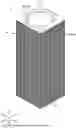
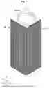
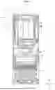
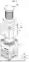
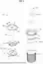
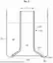
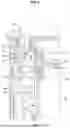
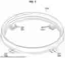
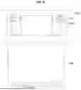
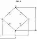
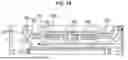
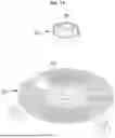

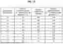

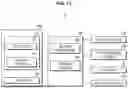
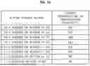
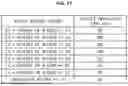


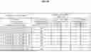

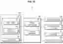
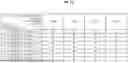

Sources:
- United States Patent and Trademark Office - verify current appl. status at the USPTO↗
Similar patent applications:
- » 20250012465
METHOD FOR CONTROLLING HUMIDIFIER, APPARATUS, HUMIDIFIER, AND STORAGE MEDIUM - » 20150330643
Evaporative humidifier and control method thereof - » 20180216839
Air humidifying device and method of moving the same, air humidifying system and control method thereof, and monitoring system - » 20230327151
HUMIDIFIER CONTROL APPARATUS AND METHOD AND FUEL CELL SYSTEM USING THE SAME - » 20190154286
Humidifier control systems and methods - » 20190154285
Humidifier control systems and methods - » 20190154287
Humidifier control systems and methods - » 20180252420
HUMIDIFIER AND METHOD FOR CONTROLLING SAME - » 20140060533
METHODS AND SYSTEM FOR HUMIDIFIER CONTROL USING ENTHALPY-BASED CALCULATION - » 20240230125
AIR-CONDITIONING SYSTEM FOR DATA COMPUTER ROOM AND METHOD FOR CONTROLLING OPERATION OF HUMIDIFYING APPARATUS THEREOF
Recent applications in this class:
- » 20260002692 2026-01-01
VENTILATION DEVICE AND AIR CONDITIONER COMPRISING SAME - » 20250354715 2025-11-20
WIRELESS REMOTE INDOOR SENSOR FOR HOME AUTOMATION - » 20250347435 2025-11-13
ENVIRONMENT CONTROL DEVICE - » 20250314393 2025-10-09
METHOD AND APPARATUS FOR OPTIMIZING HVAC CYCLING - » 20250290656 2025-09-18
MULTI-REGION TEMPERATURE MONITORING TECHNIQUES - » 20250137677 2025-05-01
AIR-CONDITIONING SYSTEM - » 20250085015 2025-03-13
HYDRONIC BUILDING SYSTEMS CONTROL - » 20250075933 2025-03-06
BUILDING CHILLER/HEAT PUMP SYSTEM CARBON EMISSION REDUCTION BY SHIFTING TEMPERATURE SETPOINT - » 20250067462 2025-02-27
CONTROLLING A HEATER ASSEMBLY FOR AN AIR CONDITIONER UNIT UTILIZING TEMPERATURE SENSORS - » 20250067461 2025-02-27
SINGLE BANK RESISTANCE HEATER FOR AN AIR CONDITIONER UNIT