FIXING MEMBER OF HEAT EXCHANGER
US20260132995A1
2026-05-14
19/251,893
2025-06-27
Smart Summary: A fixing member is designed to hold a heat exchanger in place on a vehicle. It is made from a type of plastic and has a base that attaches to the vehicle's body. Two legs extend from the base to grip the sides of the heat exchanger, and there are claws that fit into special grooves on the heat exchanger to secure it. The inner surfaces of the legs have an insulating material to help with heat management. The tips of the claws do not touch the bottom of the grooves, allowing for proper fitting when the fixing member is installed. 🚀 TL;DR
Abstract:
A fixing member includes a body made of a resin. The body includes a base portion that is fixed to the vehicle body, two legs that extends from the base portion to sandwich a side end portion of the heat exchanger, and two engagement claws that protrude inward from the two legs to be fitted into two engagement recessed portions provided in the side end portion of the heat exchanger. The fixing member is further provided with an insulating material disposed on inner surfaces of the two legs. The two engagement claws of the body have tip ends where the insulating material is not provided. The two engagement claws of the body have a length where the tip ends of the two engagement claws do not contact bottom surfaces of the two engagement recessed portions of the heat exchanger when the fixing member is mounted to the heat exchanger.
Assignee:
- TOYOTA JIDOSHA KABUSHIKI KAISHA 26,433 🇯🇵 Toyota-shi, Japan
Applicant:
Interested in similar patents?
Get notified when new applications in this technology area are published.
Classification:
F28F9/013 » CPC main
Casings; Header boxes; Auxiliary supports for elements; Auxiliary members within casings; Auxiliary supports for elements for tubes or tube-assemblies
Description
CROSS-REFERENCE TO RELATED APPLICATION
This application claims priority to Japanese Patent Application No. 2024-196461 filed on Nov. 11, 2024. The disclosure of the above-identified application, including the specification, drawings, and claims, is incorporated by reference herein in its entirety.
BACKGROUND
1. Technical Field
The present specification discloses a fixing member of a heat exchanger that fixes the heat exchanger to a vehicle body.
2. Description of Related Art
A vehicle is equipped with heat exchangers, such as a condenser of an air conditioner and a radiator used for cooling an engine. The heat exchangers are fixed to a vehicle body using fixing members.
Japanese Unexamined Patent Application Publication No. 2019-119997 (JP 2019-119997 A) discloses a fastener made of a resin for attaching a heat insulating material to a girder (a portion that supports a floor of a building).
SUMMARY
Fixing a heat exchanger, in which an outer surface is at a high temperature, to a vehicle body by using a fixing member made of a resin having relatively low heat resistance is desirable.
The present specification discloses a fixing member that includes a body made of a resin and fixes a heat exchanger to a vehicle body.
The fixing member of the heat exchanger disclosed in the present specification includes the body made of a resin. The body includes: a base portion that is fixed to the vehicle body; two legs that extend from the base portion to sandwich a side end portion of the heat exchanger; and two engagement claws, each protruding inward from a corresponding one of the two legs to be fitted into a corresponding one of two engagement recessed portions provided in the side end portion of the heat exchanger. The fixing member further includes insulating materials, each disposed on an inner surface of a corresponding one of the two legs and interposed between the inner surface and the side end portion of the heat exchanger. The two engagement claws of the body have respective tip ends where the insulating materials are not provided. The two engagement claws of the body have a length such that the tip ends of the two engagement claws do not contact bottom surfaces of the two engagement recessed portions of the heat exchanger when the fixing member is mounted to the heat exchanger.
With this configuration, since the two legs of the resin-made body of the fixing member are in contact with the heat exchanger through the insulating materials, the heat exchanger having the outer surface that becomes a high temperature can be held by the two legs.
In a process of mounting the fixing member to the heat exchanger, an operator spreads the two legs of the body and places the engagement claws of the two legs on the outer surface of the end portion of the heat exchanger. Then, the operator slides the fixing member to cause the two engagement claws to engage with the two engagement recessed portions of the heat exchanger. In the mounting process, in a case where the insulating materials are disposed at the tip ends of the engagement claws, when the fixing member slides, the insulating materials at the tip ends of the engagement claws may be dragged on the outer surface of the heat exchanger, and the insulating materials of other portions that are connected to the dragged portions may be peeled off from the body.
However, with the configuration, since the insulating materials are not provided at the tip ends of the engagement claws, it is possible to suppress peeling off of the insulating materials in the portions other than the tip ends of the engagement claws from the body. In a case where the fixing member is mounted to the heat exchanger, the tip ends of the engagement claws of the body do not contact the bottom surfaces of the engagement recessed portions of the heat exchanger. That is, there is a gap between the tip end of each of the engagement claws of the body and the bottom surface of each of the engagement recessed portions of the heat exchanger. Therefore, the deterioration of the engagement claws of the body (made of a resin) due to the heat of the outer surface of the heat exchanger can be suppressed.
In the fixing member of the heat exchanger according to the present disclosure, the body may include a crotch portion that connects the base portion and roots of the two legs, and a cutout may be provided in an inner surface of the crotch portion.
With this configuration, in the process of mounting the fixing member to the heat exchanger, the two legs of the body are easily spread by the operator when the engagement claws of the two legs are placed on the outer surface of the end portion of the heat exchanger.
In the fixing member of the heat exchanger according to the present disclosure, each of the two engagement claws of the body may have a right-angled triangular shape with an opposite side positioned on a base portion side in a sectional view along a direction in which the two legs extend.
With this configuration, the tip end of each of the engagement claws has a pointed shape. Therefore, in the process of mounting the fixing member to the heat exchanger, after the engagement claws of the two legs are placed on the outer surface of the heat exchanger and the fixing member slides on the outer surface of the heat exchanger, the frictional force between the fixing member and the heat exchanger can be reduced. In addition, after the engagement claws are engaged with the engagement recessed portions, the opposite side (vertical surface) of each of the engagement claws having a right-angled triangular-shape faces an inner surface of the engagement recessed portion, the inner surface being close to the base portion of the fixing member, so that the engagement claw is less likely to be disengaged from the engagement recessed portion. That is, the fixing member is less likely to be detached from the heat exchanger.
In the fixing member of the heat exchanger according to the present disclosure, the inner surfaces of the two legs of the body may have two jig receiving recessed portions facing each other; and a jig for widening a spacing between the two legs may be inserted into the two jig receiving recessed portions in the process of mounting the fixing member to the heat exchanger.
With this configuration, in the process of mounting the fixing member to the heat exchanger, the two legs of the body are easily spread by the operator when the engagement claws of the two legs are placed on the outer surface of the end portion of the heat exchanger.
In the fixing member of the heat exchanger according to the present disclosure, the heat exchanger may be a gas cooler of an air conditioner that uses carbon dioxide as a refrigerant.
According to the technique disclosed in the present specification, the heat exchanger can be fixed to the vehicle body by using the resin-made body of the fixing member.
BRIEF DESCRIPTION OF THE DRAWINGS
Features, advantages, and technical and industrial significance of exemplary embodiments of the disclosure will be described below with reference to the accompanying drawings, in which like signs denote like elements, and wherein:
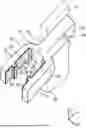
FIG. 1 is a perspective view showing a fixing member 30;
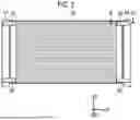
FIG. 2 is a front view schematically showing a fixed structure of a gas cooler 16;
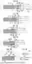
FIG. 3A is a diagram showing a process of mounting the fixing member 30 to the gas cooler 16;
FIG. 3B is a diagram showing a process of mounting the fixing member 30 to the gas cooler 16;
FIG. 3C is a diagram showing a process of mounting the fixing member 30 to the gas cooler 16;
FIG. 3D is a diagram showing a process of mounting the fixing member 30 to the gas cooler 16;
FIG. 3E is an enlarged view of a part of FIG. 3D;
FIG. 3F is a diagram showing a form of an engagement claw;
FIG. 4A is a diagram showing a process of mounting another fixing member 30a to the gas cooler 16;
FIG. 4B is a diagram showing a process of mounting the fixing member 30a to the gas cooler 16;
FIG. 4C is a diagram showing a process of mounting the fixing member 30a to the gas cooler 16;
FIG. 4D is a diagram showing a process of mounting the fixing member 30a to the gas cooler 16;
FIG. 4E is a diagram showing a process of mounting the fixing member 30a to the gas cooler 16;
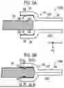
FIG. 5A is a diagram showing a process of mounting a fixing member 30b to the gas cooler 16; and
FIG. 5B is a diagram showing a process of mounting the fixing member 30b to the gas cooler 16.
DETAILED DESCRIPTION OF EMBODIMENTS
Hereinafter, embodiments will be described with reference to the drawings. The same reference numerals are given to the same elements in all the drawings, and the redundant description will be omitted. In the following description, unless otherwise specified, a term representing a direction and an orientation such as front, rear, left, right, up, and down represents a direction and an orientation with respect to a vehicle. In each drawing, an arrow FR represents a front direction, an arrow UP represents an upward direction, and an arrow LH represents a left direction.
FIG. 1 is a perspective view showing a fixing member 30. FIG. 2 is a front view schematically showing a fixed structure of a gas cooler 16. FIGS. 3A to 3F are diagrams showing a process of mounting the fixing member 30 to the gas cooler 16.
As shown in FIG. 2, the vehicle includes a gas cooler 16. The gas cooler 16 is an air-cooled condenser (radiator) that exchanges heat between a refrigerant and air in an air conditioner to dissipate the refrigerant. The gas cooler 16 constitutes a refrigeration cycle together with a compressor, an expansion valve, and an evaporator (not shown). The refrigeration cycle employs carbon dioxide as a refrigerant. In the refrigeration cycle of the carbon dioxide, the outer surface of the gas cooler 16 is at a high temperature. The fixing member 30 is used to fix the gas cooler 16 to a structure 14 of the vehicle body.
The gas cooler 16 is an example of a heat exchanger. The fixing member 30 may be used for a heat exchanger other than the gas cooler 16. The heat exchanger may be, for example, a condenser of a refrigeration cycle in which another refrigerant is used, a radiator used for cooling an engine, or the like.
As shown in FIG. 2, the fixing members 30 are disposed at the upper left, the lower left, the upper right, and the lower right end portions of the gas cooler 16. The fixing members 30 at the upper left end portion and the lower left end portion of the gas cooler 16 are fixed to the structure 14 on the left side of the vehicle. The fixing members 30 at the upper right end portion and the lower right end portion of the gas cooler 16 are fixed to a structure 14 on the right side of the vehicle. As described above, the gas cooler 16 is fixed to the two structures 14 by using the four fixing members 30.
FIG. 1 shows the fixing member 30 provided at an upper right end portion (upper left end portion in a direction related to the vehicle) of the gas cooler 16 of FIG. 2. In the following, the fixing member 30 at the upper right end portion (upper left end portion in the direction related to the vehicle) will be described, but the other fixing members 30 also have the same structure and the same mounting method is adopted. FIGS. 3A to 3F show cross sections of the gas cooler 16 and the fixing member 30 taken along the line III-III in FIG. 2. FIGS. 4A to 4E and FIGS. 5A and 5B to be described later also show cross sections of the same portions.
As shown in FIG. 1, the fixing member 30 includes a body 32 made of a resin. The body 32 includes a base portion 34, two legs 36, and two engagement claws 38. The base portion 34 is fixed to the structure 14 of the vehicle body. The base portion 34 has a through hole 35. The base portion 34 is bolted to the structure 14 by the bolt being inserted into the through hole 35. The base portion 34 may be fixed to the structure 14 using a member other than the bolt.
The two legs 36 extend from the base portion 34. As shown in FIG. 3D, the two legs 36 sandwich the side end portion of the gas cooler 16. The two engagement claws 38 protrude inward from the two legs 36. The two engagement claws 38 are fitted into two engagement recessed portions 18 provided in the side end portion of the gas cooler 16.
As shown in FIG. 1, the fixing member 30 includes an insulating material 60. The insulating material 60 is disposed on the inner surfaces 48 of the two legs 36. The insulating material is, for example, made of foamed ethylene propylene diene monomer (EPDM) and has a sheet shape. The material or the form of the insulating material is not limited. The insulating material 60 is attached to the inner surfaces 48 of the two legs 36. As shown in FIG. 3D, the insulating material 60 is interposed between the inner surfaces of the two legs 36 and the outer surface of the side end portion of the gas cooler 16.
As shown in FIG. 1, the two engagement claws 38 of the body 32 have a tip end 39 where the insulating material 60 is not provided. As shown in FIG. 3E, the two engagement claws 38 of the body 32 have a length where the tip ends 39 of the two engagement claws 38 do not contact the bottom surfaces 19 of the two engagement recessed portions 18 of the gas cooler 16 when the fixing member 30 is mounted to the gas cooler 16. As shown in FIG. 1, the body 32 includes a crotch portion 40 that connects the base portion 34 and the roots of two legs 36. A cutout 42 is provided on the inner surface of the crotch portion 40.
Next, a process of mounting the fixing member 30 to the gas cooler 16 will be described. FIGS. 3A to 3F show a process of mounting the fixing member 30 to the gas cooler 16. The operator brings the fixing member 30 close to the side end portion of the gas cooler 16 as shown in FIGS. 3A and 3B. Then, as shown in FIG. 3C, the operator spreads the two legs 36 of the body 32 and places the engagement claws 38 of the two legs 36 on the outer surface of the end portion of the gas cooler 16. Then, the operator slides the fixing member 30 to cause the two engagement claws 38 to engage with the two engagement recessed portions 18 of the gas cooler 16, as shown in FIG. 3D. In the engaged state, the front portion and the rear portion of the end surface 22 of the gas cooler 16 are in contact with the inner surfaces of the base portions of the two legs 36 through the insulating material 60.
An enlarged view of the region inside the broken line to which the reference numeral d1 is added in the upper portion of FIG. 3D is shown in FIG. 3E. FIG. 3E shows the engagement claw 38 and the engagement recessed portion 18 on the upper side (rear side in the direction related to the vehicle). The lower engagement claw 38 and the engagement recessed portion 18 (front side in the direction related to the vehicle) also have the same structure as the upper engagement claw 38 and the engagement recessed portion 18 in an up-down symmetric manner.
The embodiment described above has the configuration in which the two legs 36 of the body 32 made of a resin of the fixing member 30 are in contact with the gas cooler 16 through the insulating material 60. Therefore, the gas cooler 16 in which the outer surface is at a high temperature can be held by the two legs 36.
As described above, in the process of mounting the fixing member 30 to the gas cooler 16, the operator spreads the two legs 36 of the body 32 and places the engagement claws 38 of the two legs 36 on the outer surface of the end portion of the gas cooler 16 (see FIG. 3C). Then, the operator slides the fixing member 30 to cause the two engagement claws 38 to engage with the two engagement recessed portions 18 of the gas cooler 16 (see FIG. 3D). In the mounting process, in a case where the insulating material 60 is disposed on the tip end 39 of the engagement claw 38, there is a possibility that the insulating material 60 at the tip end 39 of the engagement claw 38 is dragged on the outer surface of the gas cooler 16 when the fixing member 30 slides. Further, when the fixing member 30 slides, there is a possibility that the insulating material 60 of another portion connected to the insulating material 60 is peeled off from the body 32.
However, according to the embodiment described above, since the insulating material 60 is not provided on the tip end 39 of the engagement claw 38, it is possible to suppress peeling off of the insulating material 60 of the portion other than the tip end 39 of the engagement claw 38 from the body 32. In a case where the fixing member 30 is mounted to the gas cooler 16, as shown in FIG. 3E, the tip end 39 of the engagement claw 38 does not contact the bottom surface 19 of the engagement recessed portion 18 of the gas cooler 16. That is, there is a gap between the tip end 39 of the engagement claw 38 and the bottom surface 19 of the engagement recessed portion 18 of the gas cooler 16. Therefore, the deterioration of the engagement claws 38 of the body 32 (made of a resin) due to the heat of the outer surface of the gas cooler 16 can be suppressed.
In the embodiment described above, the body 32 of the fixing member 30 has the cutout 42 in the inner surface of the crotch portion 40. Therefore, in a process of mounting the fixing member 30 to the gas cooler 16, the two legs 36 of the body 32 are easily spread by the operator when the engagement claws 38 of the two legs 36 are placed on the outer surface of the end portion of the gas cooler 16 (see FIG. 3C).
In the embodiment described above, the engagement claw 38 has a rectangular shape in a cross-sectional view. However, the engagement claw 38 may have a shape other than a rectangular shape in a cross-sectional view. Another form of the engagement claw 38 in the region inside the broken line to which the reference numeral d2 of FIG. 3E is added is shown in FIG. 3F.
FIG. 3F shows the engagement claw 38-1 on the upper side (rear side in the direction related to the vehicle). The lower engagement claw 38-1 (front side in the direction related to the vehicle) also has the same structure as the upper engagement claw 38-1 in an up-down symmetric manner. As shown in FIG. 3F, the engagement claw 38-1 has a right-angled triangular shape in a cross-sectional view along the direction in which the leg 36 extends, with the opposite side 45 positioned on the base portion 34 side.
With this configuration, the tip end 39 of the engagement claw 38-1 has a pointed shape. Therefore, in a process of mounting the fixing member 30-1 to the gas cooler 16, after the engagement claws 38-1 of the two legs 36 are placed on the outer surface of the gas cooler 16, when the fixing member 30-1 slides on the outer surface of the gas cooler 16, the frictional force between the fixing member 30-1 and the gas cooler 16 can be reduced. In addition, after the engagement claw 38-1 is engaged with the engagement recessed portion 18, opposite sides 45 (vertical surface) of the engagement claw 38-1 having a right-angled triangular-shape face the inner surface of the fixing member of the engagement recessed portion 18 on the base portion 34 side, so that the engagement claw 38-1 is hardly disengaged from the engagement recessed portion 18. That is, the fixing member 30-1 can be hardly detached from the gas cooler 16.
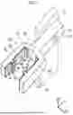
Next, another fixing member will be described. FIGS. 4A to 4E show a process of mounting another fixing member 30a to the gas cooler 16. The fixing member 30a (see FIGS. 4A to 4E) is further provided with two additional jig receiving recessed portions 52 with respect to the fixing member 30 (see FIGS. 3A to 3F) described above. Specifically, as shown in FIG. 4A, the inner surfaces of the two legs 36 of the body 32 have the jig receiving recessed portions 52 facing each other. The jig receiving recessed portion 52 may be a cutout that penetrates from the upper surface to the lower surface of the body 32. Alternatively, the jig receiving recessed portion 52 may be a cutout having a predetermined depth provided in the upper surface (or the lower surface) of the body 32. As shown in FIG. 4B, a tension bar 93 of a jig 90 that widens the spacing between the two legs 36 is inserted into the two jig receiving recessed portions 52.
The jig 90 includes a handle 91, a connecting portion 92, and a tension bar 93. The connecting portion 92 connects the handle 91 and the tension bar 93. The tension bar 93 may have a tapered shape in which the cross-sectional area gradually decreases from the upper portion to the lower portion.
The operator grips the handle 91 of the jig 90 and, as shown in FIG. 4B, inserts the tension bars 93 of the jig 90 into the two jig receiving recessed portions 52 of the fixing member 30a. As a result, the operator can easily spread the two legs 36 of the fixing member 30a.
As shown in FIG. 4C, the operator brings the fixing member 30a in which the two legs 36 are spread close to the side end portion of the gas cooler 16. The operator positions the side end portion of the gas cooler 16 between the two engagement claws 38 of the fixing member 30a. Then, the operator pulls the handle 91 of the jig 90 to remove the tension bars 93 of the jig 90 from the two jig receiving recessed portions 52. As a result, as shown in FIG. 4D, the engagement claws 38 of the two legs 36 are mounted to the outer surface of the end portion of the gas cooler 16. Then, the operator slides the fixing member 30 to cause the two engagement claws 38 to engage with the two engagement recessed portions 18 of the gas cooler 16 (see FIG. 4E).
In the fixing member 30a described above, the same effects as the fixing member 30 (see FIGS. 3A to 3F) described above can be obtained.
Next, still another fixing member will be described. FIGS. 5A and 5B show still another fixing member 30b. In the drawing, a process of mounting the fixing member 30b to the gas cooler 16 is shown. As shown in FIG. 5A, the fixing member 30b has a structure in which the fixing member 30 (see FIGS. 3A to 3F) described above is divided into two in the vertical direction (front-rear direction with respect to the vehicle). As shown in FIGS. 5A and 5B, the fixing member 30 b adopts a sandwich structure.
The fixing member 30b includes two fixing member pieces 301, 302. As shown in FIG. 5B, the operator sandwiches the side end portion of the gas cooler 16 with the two fixing member pieces 301, 302 to mount the fixing member 30b to the gas cooler 16. Then, the operator combines the two fixing member pieces 301, 302 at a portion of the base portion 34. The fastening may be performed using a bolt, a clip, a rivet, an adhesive, or the like. Then, the operator fixes the base portion 34 of the fixing member 30b to the structure 14 of the vehicle body.
The gas cooler 16 can be fixed to the structure 14 of the vehicle body by using the fixing member 30b.
Claims
What is claimed is:1. A fixing member of a heat exchanger that fixes the heat exchanger to a vehicle body, the fixing member comprising a body made of a resin, wherein:
the body includes
a base portion that is fixed to the vehicle body,
two legs that extend from the base portion to sandwich a side end portion of the heat exchanger, and
two engagement claws, each protruding inward from a corresponding one of the two legs to be fitted into a corresponding one of two engagement recessed portions provided in the side end portion of the heat exchanger,
the fixing member further includes insulating materials, each disposed on an inner surface of a corresponding one of the two legs and interposed between the inner surface and the side end portion of the heat exchanger,
the two engagement claws of the body have respective tip ends where the insulating materials are not provided, and
the two engagement claws of the body have a length such that the tip ends of the two engagement claws do not contact bottom surfaces of the two engagement recessed portions of the heat exchanger when the fixing member is mounted to the heat exchanger.
2. The fixing member according to claim 1, wherein:
the body includes a crotch portion that connects the base portion and roots of the two legs; and
a cutout is provided in an inner surface of the crotch portion.
3. The fixing member according to claim 1, wherein each of the two engagement claws of the body has a right-angled triangular shape with an opposite side positioned on a base portion side in a sectional view along a direction in which the two legs extend.
4. The fixing member according to claim 1, wherein:
the inner surfaces of the two legs of the body have two jig receiving recessed portions facing each other; and
a jig for widening a spacing between the two legs is inserted into the two jig receiving recessed portions in a process of mounting the fixing member to the heat exchanger.
5. The fixing member according to claim 1, wherein the heat exchanger is a gas cooler of an air conditioner that uses carbon dioxide as a refrigerant.
Images & Drawings included:

Sources:
- United States Patent and Trademark Office - verify current appl. status at the USPTO↗
Recent applications in this class:
- » 20260092748 2026-04-02
ADDITIVELY MANUFACTURED HEAT EXCHANGER SUPPORTS AND METHOD OF MANUFACTURE - » 20240271886 2024-08-15
Heat Exchanger - » 20240118043 2024-04-11
RADIATOR SUPPORT UPPER COVER - » 20230251046 2023-08-10
Header assembly and heat exchanger - » 20220205741 2022-06-30
FIXING DEVICE FOR HEAT EXCHANGERS OF A VEHICLE HEAT EXCHANGE SYSTEM - » 20220057150 2022-02-24
Portable Cooling Assembly - » 20220034604 2022-02-03
Submerged cooler arrangements - » 20210310753 2021-10-07
Support of heat exchangers made of wound tubes - » 20210123694 2021-04-29
Clamping system for a tube in a tube bundle - » 20200263937 2020-08-20
Bumper clip for tube type heat exchangers
Recent applications for this Assignee:
- » 20260136451 2026-05-14
POWER MODULE AND POWER CONVERSION DEVICE - » 20260136410 2026-05-14
VEHICLE PAIR SELECTION FOR EFFICIENT V2X WIRELESS COMMUNICATION AT TRAFFIC WAITING ZONES - » 20260135508 2026-05-14
ELECTRIC VEHICLE - » 20260135441 2026-05-14
DRIVING DEVICE FOR VEHICLE - » 20260135435 2026-05-14
ELECTRIC APPARATUS - » 20260135265 2026-05-14
POWER STORAGE DEVICE - » 20260135264 2026-05-14
ENERGY STORAGE DEVICE - » 20260135259 2026-05-14
BATTERY AND METHOD FOR MANUFACTURING THE SAME - » 20260135254 2026-05-14
SOLID-STATE BATTERY - » 20260135246 2026-05-14
POWER STORAGE DEVICE