DECORATIVE RING
US20260137151A1
2026-05-21
18/951,943
2024-11-19
Smart Summary: A decorative ring has a special frame that can be folded or put together in different ways. When it's unfolded, all the parts lie flat, but when it's folded, they stack in different layers. This design makes it easier and cheaper to transport because it takes up less space. People can quickly set it up at home since it comes pre-mounted and is easy to assemble. Overall, this compact design helps save money on shipping and installation. 🚀 TL;DR
Abstract:
The invention is an architectural decorative ring with a foldable or modular installation frame. It features an unfolded and folded state, with parts lying in the same plane when unfolded and in different planes when folded. This design reduces transportation space, lowering logistics costs. Consumers can easily assemble or unfold the pre-mounted decorative item, simplifying installation. The compact form during transport further minimizes expenses.
Applicant:
Interested in similar patents?
Get notified when new applications in this technology area are published.
Classification:
A41G1/04 » CPC main
Artificial flowers, fruit, leaves, or trees ; Garlands Garlands; Assembly of garlands
Description
TECHNICAL FIELD
The present invention belongs to the field of architectural decorations and relates to a decorative ring.
BACKGROUND
With the growing demand for Christmas and other festival decorations, a variety of decorative ring products have appeared on the market for use in homes, shopping malls, hotels, and other places. These decorative rings typically include a frame and decorative items for fixing and displaying festival decorations. However, despite the various design solutions for decorative rings provided by existing technologies, they still have some obvious pain points that affect the consumer experience and logistics costs. The specific issues are as follows:
-
- 1. High logistics costs: Most traditional Christmas decorative ring frames use a single fixed structure, which requires the decorative ring to occupy a large volume during transportation, leading to high logistics expenses. Especially during festival seasons, the surge in logistics demand makes transportation costs a significant issue for businesses. Moreover, the volume and weight of the decorative rings make bulk transportation more inconvenient, imposing a considerable burden on enterprises and consumers.
- 2. Complex installation process: Many existing decorative ring designs require consumers to undergo a complex installation process after receiving the product. For products with multiple components or those that require special fixation of decorative items, consumers often need to use tools for assembly or rely on complex interlocking structures. Especially for festival decorations, the complex installation process not only increases the difficulty of use for consumers but may also lead to improper installation, thus affecting the decorative effect or the safety of the decorations.
- 3. Storage space issues: Traditional decorative rings often cannot be folded or disassembled, occupying a large amount of storage space. After the festival, consumers may have difficulty storing them properly, leading to unnecessary waste of space. This issue is particularly evident for seasonal products; Christmas decorative rings are typically used only during the festival season, and the insufficient storage space causes consumers to face challenges in storing them after use.
Therefore, designing a decorative ring that is convenient for assembly and transportation has become an urgent problem to be solved.
SUMMARY
The objective of the present invention is to address the deficiencies of existing technologies by providing a decorative ring that can effectively reduce transportation costs and simplify the installation process of the decorative ring.
To achieve the aforementioned objective, the present invention adopts the following technical solution:
A decorative ring, including:
-
- an installation frame body, wherein the installation frame body has an unfolded position state and a folded position state;
- a decorative item, wherein the decorative item is mounted on the installation frame body;
- wherein, when the installation frame body is in the unfolded position state, the various parts of the installation frame body are located in the same plane; when the installation frame body is in the folded position state, the various parts of the installation frame body can be located in different planes.
Further, the installation frame body includes a first frame body and a second frame body, wherein the first frame body and the second frame body are hinged, and the first frame body and the second frame body can pivot around the hinged joint.
Further, a positioning arm is provided on the first frame body, which is used to interfere with the second frame body to thereby limit the unfolding angle of the installation frame body.
Further, the first frame body and the second frame body are provided with latching components, where the first frame body and the second frame body are fixed in place by the latching components when the installation frame body is in the unfolded position state.
Further, the latching components include a latching ball head and a latching frame body;
-
- the latching ball head is located on the positioning arm, and the second frame body is provided with a corresponding latching frame body that matches the latching ball head;
- the clearance of the latching frame body is less than the diameter of the latching ball head, and the latching frame body can undergo elastic deformation, automatically locking and preventing the latching ball head from falling off when it enters.
Further, the first frame body and the second frame body have a decorative front side and a back side with the decorative item fixed on one side;
-
- the hinge structure is installed on the back side, allowing the first frame body and the second frame body to pivot towards the back;
- the latching ball head is oriented towards the back, and the latching frame body is mounted on the back of the second frame.
Further, the installation frame body is assembled from a plurality of frame components.
Further, a connecting piece is provided at the end of each frame component, with a plurality of frame components connected end-to-end to form the installation frame body through the connecting pieces.
Further, the connecting piece is a tie strap or a buckle or a pin or a bolt or a quick-connect structure.
Further, the decorative item includes a multi-layer structure, with the inner decorative item being broken at the hinge or connection point spanning the installation frame body, and the outer decorative item covering the breakage point.
By applying the technical solution of the present invention, the decorative ring is designed with a foldable or modular installation frame body, which occupies less space during transportation and reduces logistics costs; at the same time, after consumers receive the product, the decorative item is already fixed on the installation frame body, and consumers only need to simply assemble or unfold it to use, avoiding complex installation processes. The volume of the product is greatly reduced during transportation due to the folding or modular design, thereby lowering logistics expenses. Consumers can easily assemble or unfold the decorative ring without the need for tools or complex assembly steps, enhancing the user experience. The folded decorative ring occupies minimal storage space, making it convenient for post-festival storage and reducing space waste.
The other features and advantages of the invention will be explained in the subsequent specification, and they become in part from the specification and are understood through the implementation of the present invention. The objectives and other advantages of the invention can be achieved and obtained by the structures specifically indicated in the written specification and the appended drawings.
BRIEF DESCRIPTION OF DRAWINGS
The following detailed description of the invention is provided in conjunction with the drawings, to make the aforementioned advantages of the invention more explicit.
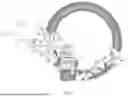
FIG. 1 is a schematic diagram of a decorative ring according to the present invention;
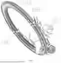
FIG. 2 is a schematic diagram of an embodiment of a decorative ring according to the present invention;
FIG. 3 is a folded schematic diagram of an embodiment a decorative ring according to the present invention;
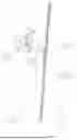
FIG. 4 is a side view of the folded embodiment of a decorative ring according to the present invention;
FIG. 5 is an unfolded schematic diagram of an embodiment of a decorative ring according to the present invention;
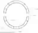
FIG. 6 is a schematic diagram of another embodiment of a decorative ring according to the present invention;
FIG. 7 is a schematic diagram of the decorative item of a decorative ring according to the present invention.
DETAILED DESCRIPTION OF THE EMBODIMENTS
The following provides a detailed description of the embodiments of the invention, as exemplified in the drawings, where identical or similar reference numerals throughout the drawings denote identical or similar components or components with identical or similar functions. The embodiments described with reference to the drawings are illustrative, intended to explain the invention, and should not be construed as limiting the invention.
In the description of the invention, it should be understood that terms such as “length,” “width,” “top,” “bottom,” “front,” “rear,” “left,” “right,” “vertical,” “horizontal,” “upper,” “lower,” “inner,” “outer,” etc., indicate positional or directional relationships based on the orientation or position shown in the drawings, solely for the purpose of describing the invention and simplifying the description. They are not intended to indicate or imply that the apparatus or component must have a particular orientation, be constructed in a particular orientation, or operate in a particular orientation, and should not be construed as limiting the invention.
Furthermore, the terms “first,” “second,” etc., are used for descriptive purposes only and are not intended to indicate or imply relative importance or to imply a specific number of the features indicated. Therefore, features limited by “first,” “second,” etc., may explicitly or implicitly include one or more of the features.
In the description of the invention, “multiple” refers to two or more unless otherwise explicitly limited.
In the embodiments of the present invention, unless otherwise specified and limited, the terms “install,” “connected,” “link,” “fixed,” and similar terms should be understood in a broad sense. For example, they can refer to fixed connections, detachable connections, or integral formations; they can be mechanical connections or electrical connections; they can be direct connections or indirect connections through intermediate media; they can also refer to the internal communication between two components or the interaction relationship between two components. For those skilled in the art, the specific meanings of the above terms in the present invention can be understood based on the specific context.
Reference to FIGS. 1-7, a decorative ring comprises:
-
- The installation frame body 100, as mentioned, features the capability to be in both an expanded and a folded state.
- The decoration 200, as referred to, is mounted onto the installation frame body 100.
Among its features, when the installation frame body 100 is in the expanded position, all parts of the installation frame body 100 lie within the same plane. Conversely, when the installation frame body 100 is in the folded position, its various parts may occupy different planes. This technical solution pertains to a decorative ring, particularly suited for festive decorations during Christmas or other holidays. It is primarily utilized for holiday decorations in domestic settings, shopping malls, hotels, and other commercial environments. By integrating a foldable design with a technology for securing decorative element 200, this solution addresses the pain points associated with transportation, installation, and storage of existing decorative rings.
Building upon existing decorative ring products, this invention offers a decorative ring that is easier to transport, simpler to install, and more space-efficient for storage. Specifically, the invention employs a foldable installation frame body 100 to reduce logistics and transportation costs, and streamlines the installation process to enhance the user experience for consumers. Furthermore, it also incorporates a design that securely fastens the decorative element 200, thereby preventing safety issues or suboptimal decorative effects that may arise from improper installation by consumers.
Traditional decorative rings typically employ a single fixed structure, which occupies a significant amount of volume and weight during transportation, resulting in high logistics costs. This invention adopts a foldable design for the installation frame main body 100, allowing the decorative ring to be folded into a smaller size, thereby saving space during transportation and reducing logistics expenses. Especially during holidays, when logistics demand surges, transportation costs become a major challenge for businesses. The foldable design not only helps alleviate the transportation burden but also improves transportation efficiency and enhances economy.
In traditional decorative rings, consumers often need to install or secure the decorative items 200 themselves, which may require tools or complex plug-in structures. These intricate installation steps often increase the difficulty for consumers, affecting the product's appeal. To address this issue, in this invention, the decorative items 200 are already fixed to the installation frame main body 100 upon delivery. Consumers can use the product directly after receiving it without any additional installation. This design greatly simplifies the installation process, saves time and effort, and reduces problems caused by improper installation.
Traditional Christmas decorative rings usually cannot be folded after the holiday season, taking up a significant amount of storage space. Due to their large size, consumers often face storage difficulties after use, leading to wasted space. By adopting a foldable design, the decorative ring of the present invention can be easily folded after the holiday season, reducing its occupied space, allowing consumers to conveniently store it during non-holiday periods, saving space and avoiding unnecessary waste.
Due to the application of the folding design and the fixing structure of the decorative object 200, the present invention can not only save costs in transportation but also reduce the complexity in the production process. Traditional decorative ring products may require cumbersome assembly processes or additional processing, while the decorative object 200 in the present invention is fixed onto the main body 100 of the mounting frame, simplifying the production process, reducing production costs, and improving production efficiency.
The mounting frame body 100 of the present invention has an expanded position state and a folded position state. When the decorative ring is in the expanded position state, the parts of the mounting frame body 100 are located on the same plane, forming a complete decorative ring structure; whereas when the decorative ring is in the folded position state, the parts of the mounting frame body 100 can be located on different planes, facilitating transportation and storage. By adopting hinge, splicing, or other foldable connection structures, consumers can conveniently expand or fold the decorative ring.
The decorative object 200 is already fixed onto the mounting frame body 100 when the product is shipped, eliminating the need for consumers to assemble or adjust it themselves. This design ensures the stability and safety of the decorative object 200 by avoiding complex fixing structures and tool requirements. After receiving the product, consumers can simply expand or splice the mounting frame body 100 to complete the display of the decorative object 200, avoiding potential operational errors or detachment issues of the decorative object 200 during the installation process.
In the first embodiment, the mounting frame body 100 includes a first frame 300 and a second frame 400, wherein the first frame 300 and the second frame 400 are hinged, and the first frame 300 and the second frame 400 can flip around the hinge.
The first frame 300 and the second frame 400 are connected through a hinge structure, allowing the two frames to freely flip around the hinging point, typically a hinge or hinge assembly. When the decorative ring is in the expanded position, the first frame 300 and the second frame 400 are located on the same plane, forming a complete decorative ring frame; when the decorative ring needs to be folded, through the flipping mechanism, the two frames will be located on different planes respectively, achieving convenience for storage and transportation. During transportation or storage, the first frame 300 and the second frame 400 can be flipped and folded into a compact state, thereby reducing space occupation and lowering logistics costs. After receiving the product, consumers can easily flip the two frame parts to fully expand them, forming the final shape of the decorative ring.
The core advantage of the hinge design lies in reducing the installation difficulty for consumers. Compared to traditional decorative rings that require multi-step assembly, the frames connected using hinges have already completed the initial structural assembly during production. Consumers only need to simply expand or fold the frames during use, greatly lowering the usage threshold. Through the hinge design, the transportation state of the decorative ring can greatly compress its volume and reduce the storage space required during the logistics process. This not only effectively lowers transportation costs but also allows consumers to conveniently fold it for storage after use, occupying minimal storage space.
Most traditional decorative ring designs feature a single fixed structure, requiring a significant amount of space. However, the hinge structure in the present invention enables the two frames to be folded, not only saving space for transportation and storage but also providing a more flexible assembly method. By fixing the decorative object 200 onto the frames, consumers are eliminated from the cumbersome installation steps of the decorative object 200. They only need to flip the frames to complete the assembly of the entire decorative ring, greatly enhancing the user-friendliness of the product.
In the first embodiment, a limiting support arm 310 is provided on the first frame 300, and the limiting support arm 310 is used to interfere with the second frame 400 to limit the expansion angle of the mounting frame body 100. The limiting support arm 310, serving as a physical interference device, is installed on the first frame 300 and interferes with the expansion process of the second frame 400. Specifically, the limiting support arm 310 will come into contact with or restrict the second frame 400 during flipping, thereby limiting the expansion angle of the second frame 400. The limiting support arm 310 functions to prevent over-expansion, which could otherwise affect the overall structural stability or aesthetics of the decorative ring frame due to excessive flipping.
The design of the limiting support arm 310 ensures that the mounting frame body 100 maintains a certain angle when in the expanded position, making the decorative ring stable and aesthetically pleasing. This design avoids the potential issue of over-expansion in traditional frames, ensuring that consumers can obtain a consistent and reasonable expansion angle, thereby optimizing the product's appearance and user experience. When consumers expand the decorative ring from its folded state, the limiting support arm 310 will come into contact with the second frame 400 during its flipping process and prevent it from further expanding. Typically, the limiting support arm 310 creates a “stop” effect through physical interference or contact, thereby limiting the expansion angle of the second frame 400 and ensuring that the decorative ring does not experience excessive stretching or an asymmetrical state when expanded.
The design of the limiting support arm 310 aims to ensure the stability of the decorative ring. In the expanded position, it ensures that the frame does not experience excessive flipping or tilting, preventing deformation of the decorative object 200 or compromising the overall structural stability of the product due to uneven expansion of the frame. This is particularly important for decorative rings with aesthetic requirements, as it avoids the issue of inconsistent angles caused by excessive frame flipping. By installing the limiting support arm 310 on the first frame 300, designers effectively control the expansion angle of the frame, avoiding potential operational errors by consumers during the expansion process. Consumers only need to expand the frame without worrying about angle issues caused by excessive force or improper operation, enhancing the convenience of use.
The limiting support arm 310 is a simple and cost-effective physical structure that can effectively control the expansion angle of the frame without relying on complex mechanical parts or additional fixing devices, thereby reducing production costs. Compared to using expensive locking devices or electric adjustment structures, the limiting support arm 310 provides a low-cost and reliable solution.
By incorporating the design of the limiting support arm 310 on the first frame 300, this embodiment effectively controls the expansion angle of the decorative ring frame. This design not only ensures the stability and aesthetics of the product but also simplifies the operation process for consumers, avoiding aesthetic deficiencies or functional impairments of the decorative ring due to improper expansion angles. Meanwhile, the limiting support arm 310, as a simple and low-cost design, reduces production and assembly costs, providing an efficient and economical solution. In summary, the innovative design of the limiting support arm 310 addresses the potential angle control issues during the expansion of traditional decorative rings, enhancing product stability, user experience, and market competitiveness.
As shown in FIGS. 1-6, in the first embodiment, latching components are provided on the first frame 300 and the second frame 400. When the mounting frame body 100 is in the expanded position state, the first frame 300 and the second frame 400 are fixed in position by the latching components. The primary purpose of the latching component design is to ensure that the first frame 300 and the second frame 400 remain securely fixed in the expanded position state, preventing looseness or displacement of the frames during use and ensuring the stability of the decorative object 200 and the frame. This is particularly important for the display of holiday decorations, as any unstable connections may lead to an uneven appearance and affect the overall effect.
With the latching components, consumers only need to expand the frame and ensure that the latching components are properly engaged after receiving the decorative ring, thereby completing the fixation of the frame and avoiding cumbersome installation steps. This design that simplifies operations enhances the user experience for consumers, especially during peak holiday seasons, as it reduces the complexity of installing the decorative object 200 and improves sales and market feedback. The latching components, through physical fixation, prevent the possibility of the frame becoming loose due to external forces or prolonged use. This not only improves the safety of the decorative ring but also ensures the fixation of the decorative object 200, thereby guaranteeing the long-term use safety for consumers.
In this embodiment, the latching components serve to fix the position of the frames. When the decorative ring is expanded from its folded state to the expanded position state, the latching components will automatically or manually engage with the joint between the first frame 300 and the second frame 400, fixing them together and preventing displacement or loosening of the frames during the expansion process. The latching components typically rely on elastic, latch, or slot structures to form a reliable fixed connection between the frames, ensuring that the decorative ring does not become detached or deformed during use.
The installation of the latching components ensures that the first frame 300 and the second frame 400 can remain fixed in the expanded state, ensuring that all parts of the frames are located on the same plane. In this way, consumers do not need additional operations or tools to keep the frames stable during installation and use, reducing complexity and increasing ease of use.
The use of latching components allows the frames to be immediately fixed after expansion, eliminating the need for complex plugging or locking procedures. Compared to traditional screws, buckles, or electric control locking devices, latching components represent an efficient and low-cost solution that provides sufficient stability while reducing the complexity of production and user operation. The design of latching components can be adjusted according to different product models, types of decorative objects 200, or consumer demands. For example, the elasticity of the latching pieces, the plugging depth, and the locking method can all be customized to provide different fixation effects. This enables the product to adapt to a wider range of market needs and different designs of decorative objects 200.
The innovative design of the latching components lies in providing a stable fixing structure through simple plugging or elastic slot mechanisms after the decorative ring is expanded, preventing looseness or displacement of the frames, and thereby ensuring the stability and neat appearance of the decorative object 200. This structural design allows consumers to easily expand the decorative ring and ensures its stability during use, simplifying the installation process and improving product operability.
In the first embodiment, the latching components include a latching ball head 311 and a latching frame 410.
The latching ball head 311 is located on the limiting support arm 310, and a latching frame 410 corresponding to the latching ball head 311 is provided on the second frame 400.
The clearance of the latching frame 410 is smaller than the diameter of the latching ball head 311, and the latching frame 410 can undergo elastic deformation. When the latching ball head 311 enters, it automatically locks in place and prevents detachment.
The latching ball head 311 is designed to be located on the limiting support arm 310 and corresponds to the latching frame 410 on the second frame 400. The diameter of the latching ball head 311 is larger than the clearance of the latching frame 410, but the latching frame 410 has a certain elasticity and can undergo deformation. When the first frame 300 and the second frame 400 are expanded and reach the set position, the latching ball head 311 will insert into the clearance of the latching frame 410. Since the clearance of the latching frame 410 is smaller than the diameter of the latching ball head 311, when the latching ball head 311 enters the latching frame 410, the latching frame 410 will undergo elastic deformation, allowing it to “enclose” the latching ball head 311 and form a secure lock. After the latching ball head 311 enters, the latching frame 410 will return to its original shape, automatically locking the latching ball head 311 and preventing the frames from loosening or falling off.
When the latching ball head 311 is connected to the latching frame 410, a stable locking structure is formed between the frames. During the use of the expanded decorative ring, the cooperation between the latching ball head 311 and the latching frame 410 prevents the frames from accidentally separating, avoiding inconvenience for consumers caused by frame looseness during use.
The design of the latching ball head 311 and the latching frame 410 not only simplifies the installation process of the frames but also enhances the consumer experience by avoiding complex assembly steps. Consumers can easily complete the assembly of the decorative ring by simply expanding the frames and ensuring proper engagement, without worrying about fixation issues.
In the first embodiment, the side where the decorative object 200 is fixed on the first frame 300 and the second frame 400 is defined as the decorative front 10, and the other side is defined as the back 20.
In the first embodiment, the side of the first frame 300 and the second frame 400 where the decorative object 200 is fixed serves as the decorative front 10, while the opposite side is designated as the back 20. The hinged structure, which enables the first frame 300 and the second frame 400 to flip towards the back 20, is installed on this back side.
The latching ball head 311 is oriented towards the back 20, and the latching frame 410 is installed on the back 20 of the second frame. When the product is folded, the decorative object 200 is located on the outer side of the frame, rather than the inner side. This avoids direct contact between the decorative object 200 and other components during the folding process, reducing compression and wear on the decorative object 200 during transportation and preserving its integrity. By installing the hinged structure on the back 20, the first frame 300 and the second frame 400 can flip towards the back 20. This structural design keeps the decorative object 200 facing outwards, effectively preventing it from being pressed or squeezed when folded inwards.
The latching ball head 311 is oriented towards the back 20, while the latching frame 410 is installed on the back 20 of the second frame. This design avoids the decorative object 200 from covering the latching frame 410, preventing interference with the fixation of the latching components, and ensures the stability of the decorative ring after it is expanded, avoiding insecure latching during the installation process. The folding structure on the back 20 reduces the possibility of the decorative object 200 being compressed during transportation, especially when the decorative ring is folded. If the decorative object 200 faces inwards, it is prone to contact and be squeezed by the frame. However, the current design keeps the decorative object 200 facing outwards, avoiding this issue.
As shown in FIG. 6, in the second embodiment, the installation frame body 100 is assembled from several frame components 500. By dividing the installation frame body 100 into multiple independent frame components 500, the size and shape of the decorative ring can be flexibly adjusted as needed. Consumers can select different frame components 500 for assembly according to their actual needs, or add or reduce frame components 500 as required
In the second embodiment, designing the decorative ring as multiple assemblable frame components 500 can significantly reduce the product's volume, minimizing space occupation during transportation and thereby lowering logistics costs. After receiving the product, consumers can easily assemble the individual frame components 500 into a complete decorative ring. This design offers significant advantages in saving transportation and storage space.
Modular design not only facilitates mass production but also allows for a certain degree of customization. Companies can produce frame components 500 of different sizes or shapes according to varying market demands, and consumers can also choose the assembly method based on their needs. This flexibility enables the realization of scale advantages in production while meeting diversified market demands. The decorative ring can be disassembled according to seasonal demands, and the frame components 500 can be broken down into smaller units after the festival for easier storage. The space occupied after disassembly is much smaller than that of traditional integral frame designs, which solves the problem of large storage space required for traditional decorative objects 200.
In the second embodiment, the ends of the dry frame components 500 are equipped with connectors 600, and several frame components 500 are connected end-to-end through the connectors 600 to form the installation frame body 100. The connectors 600 play a crucial role at the ends of the frame components 500, ensuring a tight connection between each frame component 500. The connectors 600 can be cable ties, buckles, latches, bolts, quick-connect structures, etc. Depending on the connection method, consumers can easily fix each frame component 500 together to ensure the stability of the overall structure.
Even during transportation, the connectors 600 can effectively prevent the frame components 500 from loosening or falling off, thereby maintaining the integrity of the decorative ring. By designing end connectors 600, consumers can quickly and easily assemble multiple frame components 500 together. Compared to traditional fixation methods such as screws or glue, the connectors 600 enable rapid installation and disassembly without the need for tools, greatly reducing the difficulty of installation. Additionally, the design of the connectors 600 ensures precise alignment between components, avoiding situations where assembly is not aligned.
Due to the use of connectors 600 for assembling the frame components 500, the product can be transported in a smaller volume. During transportation, the components can be disassembled and compactly packaged, reducing the occupied space and weight, and significantly lowering logistics costs. After consumers receive the product, they only need to assemble the individual components using the connectors 600, making it easy to use and also allowing for disassembly into smaller pieces for storage, reducing storage space occupation. The types of connectors 600, such as buckles, latches, etc., can be flexibly adjusted according to different needs. For example, buckles can achieve rapid installation, latches can provide stronger connecting force, and quick-connect structures are suitable for scenarios requiring frequent disassembly. Consumers can choose the appropriate connection method according to their needs, to adapt to different occasions and decorative ring usage requirements.
In the second embodiment, the connectors 600 can be cable ties, buckles, latches, bolts, or quick-connect structures. The diversity of these connectors 600 brings flexibility and convenience to the assembly, disassembly, and use of the product.
Cable ties are an economical, simple, and easy-to-operate connection method, typically suitable for quick and temporary fixation. Cable ties can be directly tightened for fixation, and the installation process does not require tools, making it easy for consumers to operate. Although cable ties offer high fixation strength, they are also very easy to remove, simply by cutting them off.
The buckle structure facilitates quick installation and disassembly without the need for additional tools. Consumers can complete the fixation simply by pressing or pushing the buckle. Compared to cable ties, buckles can provide stronger fixation force, ensuring that the frame components 500 are not easily loosened during transportation and use.
The latch can precisely fix the frame components 500 in the designated position, preventing positional errors. It is suitable for structures that need to bear greater pressure or loads.
Bolt connections can withstand significant tensile and compressive forces, making them suitable for frame components 500 that require long-term stable connections. The strength of bolt connections is much higher than that of buckles or cable ties, making them suitable for decorative ring structures that need to bear larger forces. Bolt connections require tools for installation and disassembly, and the installation time may be longer. However, they are a very reliable choice when high-strength connections are required.
The quick-connect structure usually completes installation through simple actions such as clipping, rotating, or sliding, greatly shortening the time required for assembly and disassembly. This structure allows for rapid disassembly and assembly between components, facilitating transportation, storage, and flexible adjustment of usage scenarios.
As shown in FIG. 7, in this embodiment, the decorative object 200 comprises a multi-layer structure, with the inner layer decorative object 210 being broken at the hinge or connection point across the installation frame body 100, and the outer layer decorative object 220 covering the break point 230.
The inner layer decorative object 210 is broken at the hinge or connection point, ensuring that the decorative ring is not obstructed by the decorative object during the folding process. This allows the decorative ring to fold smoothly, facilitating transportation, storage, and distribution. The design of the inner layer breaking at the folding point avoids folding difficulties caused by the solidity or integrity of the decorative object, thereby ensuring the convenience and practical use of the product. The designed inner layer decorative object 210, with precise breaking positions, enables the decorative ring to fold without any external resistance and can easily fold into a compact state. The breaking design of the inner layer eliminates excess tension or resistance during the folding process, enhancing the consumer's usage experience.
The outer layer decorative object 220 covers the breaking point of the inner layer, effectively hiding the seams or creases in the folded area and enhancing the overall aesthetics of the decorative ring. Even in its folded state, the outer layer decorative object 220 maintains the appearance integrity and attractiveness of the decorative ring, ensuring that the decorative effect of the product is not compromised by folding. Through this layered decorative design, the cooperation between the inner and outer layer decorative objects 220 not only improves the visual effect but also ensures that the folded area does not appear abrupt or damaged. When consumers unfold and use it, the outer layer decorative object 220 can conceal the hinges and folding lines, making the entire decorative ring visually maintain its integrity and elegance.
Lastly, it should be noted that: the above description is merely the preferred embodiments of the present invention and is not used to limit the present invention. Although the present invention has been described in detail with reference to the aforementioned embodiments, for those skilled in the art, they can still modify the technical solutions recorded in the aforementioned embodiments or perform equivalent substitutions on some technical features therein. Any modifications, equivalent substitutions, improvements, etc., made within the spirit and principles of the present invention, shall be included within the scope of protection of the present invention.
Claims
What is claimed is:1. A decorative ring, characterized by including:
an installation frame body (100), wherein the installation frame body (100) has an unfolded position state and a folded position state;
a decorative item (200), wherein the decorative item (200) is mounted on the installation frame body (100);
wherein, when the installation frame body (100) is in the unfolded position state, the various parts of the installation frame body (100) are located in the same plane; when the installation frame body (100) is in the folded position state, the various parts of the installation frame body (100) can be located in different planes.
2. According to claim 1, the decorative ring is characterized by the installation frame body (100) including a first frame body (300) and a second frame body (400), wherein the first frame body (300) and the second frame body (400) are hinged, and the first frame body (300) and the second frame body (400) can pivot around the hinged joint.
3. According to claim 2, the decorative ring is characterized by a positioning arm (310) provided on the first frame body (300), wherein the positioning arm (310) is used to interfere with the second frame body (400) to thereby limit the unfolding angle of the installation frame body (100).
4. According to claim 3, the decorative ring is characterized by latching components provided on the first frame body (300) and the second frame body (400), wherein when the installation frame body (100) is in the unfolded position state, the first frame body (300) and the second frame body (400) are fixed in place by the latching components.
5. According to claim 4, the decorative ring is characterized by the latching components including a latching ball head (311) and a latching frame body (410);
the latching ball head (311) is located on the positioning arm (310), and the second frame body (400) is provided with a corresponding latching frame body (410) that matches the latching ball head (311);
the clearance of the latching frame body (410) is less than the diameter of the latching ball head (311) and the latching frame body (410) can undergo elastic deformation, automatically locking and preventing the latching ball head (311) from falling off when it enters.
6. According to claim 5, the decorative ring is characterized by the first frame body (300) and the second frame body (400) having a decorative front (10) and a back (20) side with the decorative item (200) fixed on one side;
the hinge structure is installed on the back (20), allowing the first frame body (300) and the second frame body (400) to pivot towards the back (20);
the latching ball head (311) is oriented towards the back (20), and the latching frame body (410) is mounted on the back of the second frame (20).
7. According to claim 1, the decorative ring is characterized by the installation frame body (100) being assembled from a plurality of frame components (500).
8. According to claim 7, the decorative ring is characterized by a connecting piece (600) provided at the end of each frame component (500), with a plurality of frame components (500) connected end-to-end to form the installation frame body (100) through the connecting pieces (600).
9. According to claim 8, the decorative ring is characterized by the connecting piece (600) being a tie strap or a buckle or a pin or a bolt or a quick-connect structure.
10. According to claim 1, the decorative ring is characterized by the decorative item (200) including a multi-layer structure, with the inner decorative item (210) being broken at the hinge or connection point spanning the installation frame body (100), and the outer decorative item (220) covering the breakage point (230).
Images & Drawings included:


Sources:
- United States Patent and Trademark Office - verify current appl. status at the USPTO↗
Similar patent applications:
- » 20190112746
Washing machine door having decorative ring, washing machine, and laundry method - » 20180361921
Decorative ring pointer cap illumination - » 20140117160
Decorative ring device for free-floating interface of aircraft interior sidewall window lining - » 20060218969
Decorative ring and guard - » 20070278236
METHOD OF MANUFACTURING A THERMOPLASTIC CONTAINER WITH DECORATIVE RINGS - » 10965631
Knob with decorative ring and snap on cap - » 20060108715
Method for making a decorative ring of a ceiling fan - » 20050061934
Tree decorator ring kit - » 20120189296
Camera with easy mounting decoration ring assembly - » 20190387144
Camera assembly and electronic device using the same, both having a decorative member mounted on a shell and comprising a decorative ring and a flange
Recent applications in this class:
- » 20260101948 2026-04-16
SWITCHABLE WREATH SYSTEM HAVING MAGNETICALLY INTERCHANGEABLE DECORATIVE ATTACHMENTS, AND A KIT FOR MAKING SAME - » 20250261716 2025-08-21
SYSTEM AND METHOD FOR FORMING A GARLAND - » 20250031791 2025-01-30
Balloon Garland Assembly And Balloon Assemblies Therefor - » 20230404193 2023-12-21
System and method for forming a garland - » 20220338582 2022-10-27
Decorative systems that include an elongated decorative element and associated methods of manufacture and use - » 20110045315 2011-02-24
Method of making a decorative article