FOOTWEAR WITH AN INTEGRATED DISPLAY
US20260137161A1
2026-05-21
19/389,869
2025-11-14
Smart Summary: Footwear has been designed with a built-in display that shows images or information. This special shoe includes different layers, like an outsole and midsole, with the display placed between them. A clear window on the bottom of the shoe allows people to see the display from the outside. The display is protected in a sealed area to keep it safe. An electronic module inside the shoe powers the display and controls what is shown. 🚀 TL;DR
Abstract:
The present invention discloses a footwear with an integrated display. The footwear comprising an outsole, a midsole, an insole, and a display assembly disposed between the outsole and the midsole. The footwear further comprises a viewing window and an electronics module. The viewing window is formed in the outsole and aligned with the display assembly. At least a portion of the display assembly is viewable from outside the footwear through the viewing window. The display assembly and the viewing window define a sealed display cavity. The electronics module is operatively coupled to the display assembly. The electronic module comprises a controller and a power source configured to drive the display assembly for presentation of dynamic visual content.
Applicant:
Interested in similar patents?
Get notified when new applications in this technology area are published.
Classification:
A43B3/36 » CPC main
Footwear characterised by the shape or the use with electrical or electronic arrangements with light sources
A43B3/48 » CPC further
Footwear characterised by the shape or the use with electrical or electronic arrangements with transmitting devices, e.g. GSM or WiFi
A43B1/08 IPC
Footwear characterised by the material made of metal
Description
CROSS-REFERENCE TO RELATED APPLICATION
The present application claims the benefit of US provisional application 63/721,586 entitled, “Customizable Footwear with Embedded and Replaceable Art Display”, filed on 18 Nov. 2024, the contents of which are hereby incorporated by reference.
TECHNICAL FIELD
The present invention generally relates to a footwear. More particularly, the present invention related to the footwear with an integrated display for dynamic visual content presentation, including location-based advertising.
BACKGROUND
Conventional footwear has been primarily developed to enhance physical performance, provide comfort, and ensure durability during a wide range of physical activities. The footwear design is evolved largely centered on improving factors including visual representation, banding, cushioning, traction, support, breathability, and ergonomic fit. The visual representation and branding are important aspects of footwear design. Further, the visual features incorporated into traditional footwear remain predominantly static and non-interactive. The patterns, colors, and logos are typically fixed during manufacturing, resulting in a finished product that offers little opportunity for dynamic visual communication or post-production customization.
However, the static branding confines footwear to a single and unchanging aesthetic look. Further, static branding restricts creative flexibility and limits the manufacturer's ability to adapt the footwear design to evolving fashion trends. As the design becomes outdated or falls out of trend, the visual appeal of the product diminishes even if the footwear retains its structural integrity and functional performance. Further, a few patent references related to the footwear having a display system are discussed as follows.
US20240041155 of Markus BOCK et. al., entitled “Article of footwear having a display system” discloses a display system for an article of footwear includes a display device with an optoelectronic display, a control module that is configured to communicate with the display device, and a power source. The display device is configured to be removably received within a receptacle formed in the article of footwear such that the optoelectronic display is visible from an outside of the article of footwear when the display device is received within the receptacle.
U.S. Pat. No. 11,122,852 of Christopher Andon et. al., entitled “Intelligent electronic footwear and logic for navigation assistance by automated tactile, audio, and visual feedback” discloses a method for operating an intelligent electronic shoe (IES) includes receiving, e.g., via a controller through a wireless communications device from a GPS satellite service, location data of a user. The controller also receives, e.g., from a backend server-class computer or other remote computing node, location data for a target object or site, such as a virtual shoe hidden at a virtual spot. The controller retrieves or predicts path plan data including a derived route for traversing from the user's location to the target's location within a geographic area. The controller then transmits command signals to a navigation alert system mounted to the IES's shoe structure to output visual, audio, and/or tactile cues that guide the user along the derived route.
Despite the extensive range of footwear with the display system in the market, there exists a need to provide continued improvements and alternative designs that enhance user comfort and eliminate the reliance on static designs and representations completely.
SUMMARY
The present invention discloses a footwear with an integrated display. The footwear comprising an outsole, a midsole, an insole, a display assembly, a viewing window, and an electronics module. The display assembly is disposed between the outsole and the midsole. The display assembly comprises a flexible organic light-emitting diode (OLED) panel and being located immediately above the outsole. The display assembly is encapsulated in an optically clear urethane encapsulant. The display assembly further includes strain-relief features including structural regions or materials to accommodate bending during gait. The display assembly further includes at least one of optical diffuser and anti-glare layer to improve perceived uniformity and visibility under ambient lighting. The outsole comprises discrete traction islands forming a ring surrounding the viewing window. The ring having a width and a height relative to the window surface, and flex groove patterns positioned to preserve gait flexibility while mechanically shielding edges of the viewing window from direct ground contact.
The footwear further comprises a sealing interface, one or more routing channels, a plurality of conductors, and a thermal management layer. The sealing interface comprises an overmoulded lip or a gasket extending around a perimeter of the viewing window and the encapsulated display assembly to seal the viewing window to the display assembly and define the sealed display cavity. The sealed display cavity is fluidly isolated from the electronics cavity. The routing channels in at least one of the outsoles or the midsole conveying electrical conductors between the electronics module and the display assembly. The plurality of conductors extending from the electronics module to the display assembly via sealed feed-throughs or overmoulded channel seals to maintain the fluidic isolation between the sealed display cavity and the electronics cavity.
The thermal management layer is positioned between the display assembly and the outsole to distribute heat generated during operation. The footwear further comprises a thermal spreader positioned adjacent to the display assembly to distribute heat generated during operation of the display assembly. In one embodiment, the thermal spreader is formed of at least one of graphite and aluminium. The viewing window formed in the outsole and aligned with the display assembly. At least a portion of the display assembly is viewable from outside the footwear through the viewing window. The display assembly and the viewing window define a sealed display cavity. The viewing window comprises a transparent or translucent window formed of an elastomer, polymer, or glassy material, optionally with an abrasion-resistant layer, and exhibiting visible-light transmittance and haze compatible with viewing the display during normal use.
The electronics module is operatively coupled to the display assembly. The electronics module comprises a wireless interface configured to receive image data or control information from an external device and to update content on the display assembly. The wireless interface comprises at least one of a Bluetooth® Low Energy (BLE) link, Wi-Fi connection, cellular communication link, or other short-range or wide-area wireless protocol. The external device comprises a mobile device or network-connected computing device. The electronics module is configured to receive location data from a paired mobile device and to select content for display based at least in part on the location data. The content comprises an advertisement selected according to one or more of: (i) membership of the mobile device within a geofenced area; (ii) proximity to a point of interest; and (iii) identification of a venue. The selection of the advertisement further depends on time-of-day or scheduled event metadata associated with the location.
The electronics module caches multiple advertisements and automatically switches the displayed advertisement upon detecting that the mobile device has crossed a geofence boundary. The electronics module receives campaign updates from a remote server via the paired mobile device and selects advertisements based on advertiser campaign parameters resolved using the location data. The electronic module comprises a controller and a power source configured to drive the display assembly.
The controller is configured to render images and animations on the display assembly. The controller is configured to map uploaded images to pixel coordinates of the flexible OLED panel, including scaling and dithering appropriate to the panel. The controller and one or more program modules executed in the mobile device or the controller are configured such that an average radio duty cycle during execution of a location-based content campaign does not exceed 5% over a 10-minute interval, by employing on-device caching and scheduled content updates
The power source is rechargeable via a wireless inductive charging interface comprising a receiver coil disposed within a sole stack and configured to couple through the outsole to an external charging pad placed beneath the footwear. The power source is rechargeable via a wireless inductive charging interface comprising a receiver coil located beneath or within the insole and configured to couple to an external charging pad placed on top of the insole when the insole is exposed. The inductive charging interface further comprises a ferrite backing layer and alignment configurations configured to improve coupling efficiency and reduce stray heating during charging of the footwear.
In another embodiment, the footwear comprises an outsole, a midsole, an insole, and a display assembly integrated within the footwear. The display assembly comprises a flexible display panel and being positioned in or adjacent to at least one of the outsole, midsole, or upper portions of the footwear. Further, a viewing window is formed in an exterior surface of the footwear and aligned with the display assembly. Further, at least a portion of the display assembly is viewable from outside the footwear through the viewing window. The display assembly and the viewing window defining a sealed display cavity. Further, an electronics module is operatively coupled to the display assembly. The electronics module comprising a controller and a power source configured to drive the display assembly for presentation of dynamic visual content.
In one embodiment, the dynamic visual content presented on the display assembly may comprise any type of digital content, including but not limited to digital artworks, non-fungible tokens (NFTs), animations, images, text, patterns, icons, logos, video content, or other forms of digital media. The content may be pre-stored in the electronics module or received from an external device or network via wired or wireless communication interfaces. In some examples, the displayed content may be personalized, updated, or dynamically changed based on user input, environmental conditions, or data received from external sources.
The above summary contains simplifications, generalizations and omissions of detail and is not intended as a comprehensive description of the claimed subject matter but, rather, is intended to provide a brief overview of some of the functionality associated therewith. Other systems, methods, functionality, features and advantages of the claimed subject matter will be or will become apparent to one with skill in the art upon examination of the following figures and detailed written description.
BRIEF DESCRIPTION OF THE DRAWINGS
The description of the illustrative embodiments can be read in conjunction with the accompanying figures. It will be appreciated that for simplicity and clarity of illustration, elements illustrated in the figures have not necessarily been drawn to scale. For example, the dimensions of some of the elements are exaggerated relative to other elements. Embodiments incorporating teachings of the present disclosure are shown and described with respect to the figures presented herein, in which:
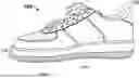
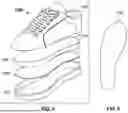
FIG. 1 exemplarily illustrates a side perspective view of a footwear, in which at least a portion of the footwear is configured to present dynamic visual content or advertisements, according to an embodiment of the present invention.
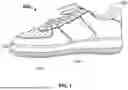
FIG. 2 exemplarily illustrates another side perspective view of the footwear, according to an embodiment of the present invention.
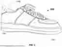
FIG. 3 exemplarily illustrates a bottom view of the footwear, in which the display assembly is presenting visual content, according to an embodiment of the present invention
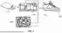
FIG. 4 exemplarily illustrates an exploded view of the footwear, according to an embodiment of the present invention.
FIG. 5 exemplarily illustrates the display assembly of the footwear, according to an embodiment of the present invention.
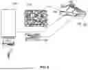
FIG. 6 exemplarily illustrates the display assembly, and an electronics module within the footwear, according to an embodiment of the present invention.
FIG. 7 exemplarily illustrates the electronics module within the footwear and external device configured to connect with the electronic module, according to an embodiment of the present invention.
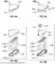
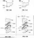
FIG. 8A exemplarily illustrates a footwear with a screw-based fastening mechanism, according to an embodiment of the present invention.
FIG. 8B exemplarily illustrates an exploded view of the footwear with the screw-based fastening mechanism, according to an embodiment of the present invention.
FIG. 9A exemplarily illustrates a footwear with a clip-based fastening mechanism, according to an embodiment of the present invention.
FIG. 9B exemplarily illustrates an exploded view of the footwear with the clip-based fastening mechanism, according to an embodiment of the present invention.
FIG. 10A exemplarily illustrates a footwear with a magnet-based fastening mechanism, according to an embodiment of the present invention.
FIG. 10B exemplarily illustrates an exploded view of the footwear with the magnet-based fastening mechanism, according to an embodiment of the present invention.
FIG. 11A exemplarily illustrates a footwear with a clip-based fastening mechanism, according to another embodiment of the present invention.
FIG. 11B exemplarily illustrates an exploded view of the footwear with the clip-based fastening mechanism, according to another embodiment of the present invention.
DETAILED DESCRIPTION OF EXAMPLE EMBODIMENTS
A description of embodiments of the present invention will now be given with reference to the Figures. It is expected that the present invention may be embodied in other specific forms without departing from its spirit or essential characteristics. The described embodiments are to be considered in all respects only as illustrative and not restrictive.
Referring to FIG. 1 to FIG. 7, a footwear 100 comprises an outsole 102, a midsole 104, an insole 106, a display assembly 108, a viewing window 110, and an electronics module. Referring to FIG. 3 to FIG. 5, the display assembly 108 is disposed between the outsole 102 and the midsole 104. The display assembly 108 comprises a flexible organic light-emitting diode (OLED) panel and being located immediately above the outsole 102. The display assembly 108 is encapsulated in an optically clear urethane encapsulant. In one embodiment, the clear urethane could be smooth-on clear flex 95. In one embodiment, the display assembly 108 is encapsulated in an optically clear adhesive with silicone fillets at transitions. In embodiments, the display assembly 108 extends across substantially a full planform area of the sole, or occupies only a region of the sole, for example, heel, midfoot, or forefoot region.
The display assembly 108 is encapsulated to maintain display performance during flexing of footwear 100 associated with physical activity. Further, the display assembly 108 is over moulded to avoid exposure of the display assembly 108 to liquids and debris. The over moulded of the display assembly 108 reduces strain at transition zones of the footwear 100 during flexing associated with physical activity. The display assembly 108 is the flexible OLED panel laminated within the multi-layer optically clear elastomeric stack. The stack is configured to position the neutral bending region proximate the OLED plane. In one embodiment, the display assembly 108 extends across at least 80% of a planform area of the sole. In another embodiment, the display assembly 108 occupies at most 40% of a planform area of the sole. In one embodiment, the display assembly 108 is located in at least one of a heel region, a midfoot region, or a forefoot region of the sole.
The display assembly 108 further includes strain-relief features to accommodate bending during gait. The display assembly 108 further includes at least one of optical diffuser and anti-glare layer to improve perceived uniformity and visibility under ambient lighting. The outsole 102 comprises discrete traction islands forming a ring surrounding the viewing window 110. The ring having a width and a height relative to the window surface, and flex groove patterns positioned to preserve gait flexibility while mechanically shielding edges of the viewing window 110 from direct ground contact. The ring surrounding the viewing window 110 is an abrasion shield comprising a thermoplastic polyurethane (TPU). In one embodiment, the ring comprises a thickness ranging from 0.4 to 0.8 mm, a width ranging from 6 to 12 mm, and a height of 3 mm. The assembled outsole-window specimen, after 1,000 abrasion cycles conducted in accordance with discrete traction islands form a ring surrounding the viewing window 110 with a width of 6-12 mm and a height of at least 3 mm relative to the window surface.
The footwear 100 further comprises a sealing interface, one or more routing channels, a plurality of conductors, and a thermal management layer. The sealing interface comprises an overmoulded lip or a gasket extending around a perimeter of the viewing window 110 and the encapsulated display assembly 108 to seal the viewing window 110 to the display assembly 108 and define the sealed display cavity. The sealed display cavity is fluidly isolated from the electronics cavity. The routing channels in at least one of the outsoles 102 or the midsole 104 conveying electrical conductors between the electronics module and the display assembly 108. The plurality of conductors extending from the electronics module to the display assembly 108 via sealed feed-throughs or overmoulded channel seals configured to maintain the fluidic isolation between the sealed display cavity and the electronics cavity.
The thermal management layer is positioned between the display assembly 108 and the outsole 102 to distribute heat generated during operation. The footwear 100 further comprises a thermal spreader positioned adjacent to the display assembly 108 to distribute heat generated during operation of the display. The thermal spreader is formed of at least one of graphite and aluminium.
The viewing window 110 is formed in the outsole 102 and aligned with the display assembly 108. At least a portion of the display assembly 108 is viewable from outside the footwear 100 through the viewing window 110. The display assembly 108 and the viewing window 110 define a sealed display cavity. The viewing window 110 comprises a transparent or translucent window formed of an elastomer, polymer, or glassy material, optionally with an abrasion-resistant layer, and exhibiting visible-light transmittance and haze compatible with viewing the display during normal use. The viewing window 110 is made up of a polymer material. In one embodiment, the polymer material comprises a thickness ranging from 1.5 millimeter (mm) to 2.0 mm and a hardness ranging from 85 to 92 on a shore A hardness scale. In one embodiment, the polymer material could be a polyurethane. In another embodiment, the polymer material could be a thermoplastic elastomer. In one embodiment, the viewing window 110 renders at least 25% of a platform area of the display assembly 108 viewable from outside the footwear 100. Referring to FIG. 3 to FIG. 5, the display assembly 108 comprises a shape complementary to the sole portion, such that substantially the entire sole portion of the footwear 100 is capable of displaying visual content 146 through the translucent window in the outsole 102.
The electronics module is operatively coupled to the display assembly 108. In one embodiment, the electronics module is configured to connected to an external device 114. The external device 114, for example, includes external computing device. The electronics module comprises a wireless interface configured to receive image data or control information from the external device 114 and to update content on the display assembly 108. The wireless interface comprises at least one of a Bluetooth® Low Energy (BLE) link, Wi-Fi connection, cellular communication link, or other short-range or wide-area wireless protocol. The external device 114 comprises a mobile device or network-connected computing device.
For an example, the electronics module configured to receive image data over a Bluetooth Low Energy link from an external computing device or external device 114 and to update content on the display assembly 108. The external computing device could be a mobile device. The electronics module further comprises a Mobile Industry Processor Interface (MIPI) connector, an earphone connector, a Mini High-Definition Multimedia Interface (Mini HDMI) compatible interface, a Universal Serial Bus (USB) interface, and a Flexible Printed Circuit (FPC) connector. In one embodiment, the earphone connector could be 3.5 mm. In one embodiment, the USB interface includes Type-C. The electronics module further comprises one or more connectors configured to transmit and receive data to and from one or more external devices. The electronics module is located between the footwear bed and the outsole, for example, within the cavity beneath the insole and above the midsole, the cavity being covered by the insole and serviceable by removing the insole. In other embodiment, the electronics module is embedded within the insole as a laminated assembly.
The electronics module is configured to receive location data from a paired mobile device and to select content for display based at least in part on the location data. The mobile device is configured to obtain location data from an operating system including location service via a mobile application. The content comprises an advertisement selected according to one or more of: (i) membership of the mobile device within a geofenced area; (ii) proximity to a point of interest; and (iii) identification of a venue. The selection of the advertisement further depends on time-of-day or scheduled event metadata associated with the location. The content includes, but not limited to, one or more venue messages, at least a branding, and advertisement. The mobile device is further configured to query a remote content service that resolves advertiser campaign parameters against location and profile inputs to return content for display, and to cache multiple items and automatically switch content when a geofence boundary is crossed, thereby preserving operation when connectivity is interrupted. Referring to FIG. 1 and FIG. 3, a portion of the footwear 100 is provided with patterns 144 indicating that the area is illuminated and configured to display dynamic visual content 146, for example, advertisements through the display assembly 108.
In some embodiments, the dynamic visual content 146 presented on the display assembly 108 may comprise any type of digital content, including but not limited to digital artworks, non-fungible tokens (NFTs), animations, images, text, patterns, icons, logos, video content, or other forms of digital media. The content 146 may be pre-stored in the electronics module or received from an external device 114 or network via wired or wireless communication interfaces. In some examples, the displayed content 146 may be personalized, updated, or dynamically changed based on user input, environmental conditions, or data received from external sources.
The electronics module caches multiple advertisements and automatically switches the displayed advertisement upon detecting that the mobile device has crossed a geofence boundary. The caching process is configured to temporarily retain the input data within the electronics module to facilitate efficient processing, and support operations during interruptions of the communication module. The electronics module receives campaign updates from a remote server via the paired mobile device and selects advertisements based on advertiser campaign parameters resolved using the location data. Referring to FIG. 6 and FIG. 7, the electronics module comprises one or more electronic components (112A, 112B, 112C). The electronics module comprises a controller. The electronic module further comprises aa power source. The power source and the controller is configured to drive the display assembly 108 is disposed within the sole of the footwear 100. The controller could be a Microcontroller Unit (MCU). The controller is configured to employ on-device caching and scheduled content updates such that the average radio duty cycle during execution of a location-based content campaign does not exceed 5% over a 10-minute interval. The controller is further configured to perform cache eviction and geofence transition handling to ensure timely content changes with reduced radio usage when connectivity is intermittent.
The controller is configured to render images and animations on the display assembly 108. The controller is configured to map uploaded images to pixel coordinates of the flexible OLED panel, including scaling and dithering appropriate to the panel. The controller and one or more program modules executed in the mobile device or the controller are configured such that an average radio duty cycle during execution of a location-based content campaign does not exceed 5% over a 10-minute interval, by employing on-device caching and scheduled content updates. The mobile application obtains content from local storage or from a remote content service, converts the content to a format suitable for the selected display type and transmits the formatted content to the controller. The display type includes the Organic Light Emitting Diode (OLED) display type for pixel-mapped display and a Light Emitting Diode (LED) display type for address-mapped display.
The power source is rechargeable via a wireless inductive charging interface comprising a receiver coil disposed within a sole stack and configured to couple through the outsole 102 to an external charging pad placed beneath the footwear 100. The power source is rechargeable via a wireless inductive charging interface comprising a receiver coil located beneath or within the insole 106 and configured to couple to an external charging pad placed on top of the insole 106 when the insole 106 is exposed. In one embodiment, the external charger comprises the wireless charging pad with a Qi-compatible wireless inductive interface. The inductive charging interface further comprises a ferrite backing layer and alignment features configured to improve coupling efficiency and reduce stray heating during charging of the footwear 100.
In some embodiments, the replaceable insole access mechanism is configured to selectively secure and release the insole from the footwear 100. The replaceable insole access mechanism comprises one or more fastening elements such as, screw-based, clip-based, or magnet-based connectors or fastening mechanism. Referring to FIG. 8A and FIG. 8B, in another embodiment, the present invention discloses the footwear 100 with a screw-based fastening mechanism. The footwear 100 comprises the insole 106, and one or more layers (118A, 118B, 118C, 118D) and a sidewall 120 defining the outsole 102 and midsole 104. The layers (118A, 118B, 118C, 118D) include at least three protective layers (118B, 118C, 118D). The footwear 100 further comprises one or more screw sockets 122 positioned on the sidewall 120, and one or more screws 124 configured to engage with the screw sockets 122, thereby fastening the different portions of the footwear 100.
Referring to FIG. 9A and FIG. 9B, in another embodiment, the present invention discloses the footwear 100 with a clip-based fastening mechanism. The footwear 100 comprises the insole 106, and one or more layers (126A, 126B, 126C, 126D) and the sidewall 120 defining the outsole 102 and midsole 104. The footwear 100 comprises at least one clip member 128 and a clip socket 130. The clip member 128 is attached at the rear portion of the insole 106 engages with the clip socket 130 positioned at the rear portion of the sidewall 120. The engagement between the clip member 128 and the clip socket 130 securely fasten different portions of the footwear 100. The clip socket 130 further comprises a releasing member configured to detach the clip member 128 from the clip socket 130.
Referring to FIG. 10A and FIG. 10B, in another embodiment, the present invention discloses the footwear 100 with a magnet-based fastening mechanism. The footwear 100 comprises the insole 106, and one or more layers and the sidewall 120 defining the outsole 102 and midsole 104. The layers are magnetic layers (132A, 132B). The layers include one or more magnetic portions. The magnetic layers (132A, 132B) are configured to securely fasten the insole to the outsole, thereby fastening the different portions of the footwear 100. The footwear 100 further comprises at least one release button 134 positioned on the sidewall 120. The button 134 is configured to detach the magnetic layers (132A, 132B).
Referring to FIG. 11A and FIG. 11B, in another embodiment, the present invention discloses the footwear 100 with a clip-based fastening mechanism. The footwear 100 comprises the insole 106, and one or more layer (136A, 136B) and the sidewall 120 defining the outsole 102 and midsole 104. The layer 136A include a thick material configured to provide support. The footwear 100 further comprises one or more adjustable clip members 138 and one or more clip sockets 140. The adjustable clip members 138 are positioned along an inner portion of the side wall 120, and the clip sockets 140 are positioned at the edges of the layer 136B. The adjustable clip members 138 are configured to engage with the clip sockets 140, thereby fastening the different portions of the footwear 100. The footwear 100 further comprises the button 142 positioned on the rear portion of the side wall 120. The button 142 is configured to detach the layer 136B by unlocking the adjustable clip members, thereby allowing separation of different portions of the footwear 100.
In some embodiments, the footwear 100 further comprises different groove patterns. The groove patterns are on a rear portion of the outsole 102, configured to preserve gait flexibility. As used herein, the term “groove patterns” refers to one or more recessed channels, contours, or indentations formed on a surface of the footwear 100. The groove patterns may include linear, curved, or multi-directional geometries and are configured to facilitate controlled flexing of the sole, enhance traction, and manage deformation during gait or ground contact.
In one embodiment, at least one receiver coil is positioned within the sole stack of the footwear 100 and configured to receive the power from the external charging pad positioned beneath the outsole 102. In another embodiment, at least one receiver coil is positioned within the insole 106 and configured to receive the power from the external charging pad positioned on top of the insole 106 in an exposed state. In one prototype, the controller is positioned along with the battery above and under the insole 106. The footwear 100 further comprises a charging interface accessible from the interior by lifting the insole 106.
In one embodiment, a method to manufacture the footwear 100 with integrated display assembly 108. At one step, the display assembly 108 is positioned between the outsole 102 and the midsole 104 of the footwear 100. At another step, the display assembly 108 is encapsulated in the multi-layer optically clear elastomeric stack. At yet another step, the routing channels are formed in the soles of the footwear 100. At yet another step, the electronics module is positioned beneath or within the insole 106. At yet another step, the viewing window 110 is formed in the outsole 102 aligned with the display assembly 108. For example, the prototype is further configured to demonstrate encapsulated OLED and LED display assemblies integrated within the sole having the viewing window 110 in the outsole 102, Bluetooth Low Energy (BLE) connectivity to the mobile device, and location-triggered geofence content switching with cached fallback operation. Advantageously, the footwear 100 is designed to provide comfort across a wide range of users, including performance footwear, lifestyle sneakers, and promotional and brand activation products. The footwear 100 is durable and has fully integrated display systems that are capable of presenting context-aware content based on proximity of location detected.
While the disclosure has been described with reference to exemplary embodiments, it will be understood by those skilled in the art that various changes may be made and equivalents may be substituted for elements thereof without departing from the scope of the disclosure. In addition, many modifications may be made to adapt a particular system, device or component thereof to the teachings of the disclosure without departing from the essential scope thereof. Therefore, it is intended that the disclosure not be limited to the particular embodiments disclosed for carrying out this disclosure, but that the disclosure will include all embodiments falling within the scope of the appended claims. Moreover, the use of the terms first, second, etc. do not denote any order or importance, but rather the terms first, second, etc. are used to distinguish one element from another.
The terminology used herein is for the purpose of describing particular embodiments only and is not intended to be limiting of the disclosure. As used herein, the singular forms “a”, “an” and “the” are intended to include the plural forms as well, unless the context clearly indicates otherwise. It will be further understood that the terms “comprises” and/or “comprising,” when used in this specification, specify the presence of stated features, integers, steps, operations, elements, and/or components, but do not preclude the presence or addition of one or more other features, integers, steps, operations, elements, components, and/or groups thereof.
The description of the present disclosure has been presented for purposes of illustration and description, but is not intended to be exhaustive or limited to the disclosure in the form disclosed. Many modifications and variations will be apparent to those of ordinary skill in the art without departing from the scope of the disclosure. The described embodiments were chosen and described in order to best explain the principles of the disclosure and the practical application, and to enable others of ordinary skill in the art to understand the disclosure for various embodiments with various modifications as are suited to the particular use contemplated.
Claims
What is claimed is:1. A footwear, comprising:
an outsole;
a midsole;
an insole, and a replaceable insole access mechanism configured to selectively permit removal and replacement of the insole;
a display assembly disposed between the outsole and the midsole;
a viewing window formed in the outsole and aligned with the display assembly, wherein at least a portion of the display assembly is viewable from outside the footwear through the viewing window, wherein the display assembly and the viewing window define a sealed display cavity, and an electronics module operatively coupled to the display assembly, wherein the electronics module comprises a controller and a power source configured to drive the display assembly.
2. The footwear of claim 1, wherein the display assembly comprises a flexible organic light-emitting diode (OLED) panel and being located immediately above the outsole, wherein the display assembly is encapsulated in an optically clear urethane encapsulant.
3. The footwear of claim 1, further comprising:
a sealing interface comprising an overmoulded lip or a gasket extending around a perimeter of the viewing window and the encapsulated display assembly to seal the viewing window to the display assembly and define the sealed display cavity, wherein the sealed display cavity is fluidly isolated from the electronics cavity;
one or more routing channels in at least one of the outsoles or the midsole conveying electrical conductors between the electronics module and the display assembly;
a plurality of conductors extending from the electronics module to the display assembly via sealed feed-throughs or overmoulded channel seals configured to maintain the fluidic isolation between the sealed display cavity and the electronics cavity, and a thermal management layer positioned between the display assembly and the outsole to distribute heat generated during operation.
4. The footwear of claim 1, wherein the controller is configured to render images and animations on the display assembly.
5. The footwear of claim 1, wherein the electronics module comprises a wireless interface configured to receive image data or control information from an external device and to update content on the display assembly, wherein the wireless interface comprises at least one of a Bluetooth® Low Energy (BLE) link, Wi-Fi connection, cellular communication link, or other short-range or wide-area wireless protocol, and wherein the external device comprises a mobile device or network-connected computing device.
6. The footwear of claim 1, wherein the display assembly further includes strain-relief features including structural regions or materials to accommodate bending during gait.
7. The footwear of claim 1, wherein the display assembly further includes at least one of optical diffuser and anti-glare layer to improve perceived uniformity and visibility under ambient lighting, and wherein the display assembly comprises a flexible display panel having a shape complementary to a sole portion of the footwear.
8. The footwear of claim 1, wherein the controller is configured to map uploaded images to pixel coordinates of the flexible OLED panel, including scaling and dithering appropriate to the panel.
9. The footwear of claim 1, wherein the electronics module is configured to receive location data from a paired mobile device and to select content for display based at least in part on the location data.
10. The footwear of claim 9, wherein the content comprises an advertisement selected according to one or more of: (i) membership of the mobile device within a geofenced area; (ii) proximity to a point of interest; and (iii) identification of a venue.
11. The footwear of claim 10, wherein selection of the advertisement further depends on time-of-day or scheduled event metadata associated with the location.
12. The footwear of claim 9, wherein the electronics module caches multiple advertisements and automatically switches the displayed advertisement upon detecting that the mobile device has crossed a geofence boundary.
13. The footwear of claim 10, wherein the electronics module receives campaign updates from a remote server via the paired mobile device and selects advertisements based on advertiser campaign parameters resolved using the location data.
14. The footwear of claim 1, wherein the power source is rechargeable via a wireless inductive charging interface comprising a receiver coil disposed within a sole stack and configured to couple through the outsole to an external charging pad placed beneath the footwear.
15. The footwear of claim 1, wherein the power source is rechargeable via a wireless inductive charging interface comprising a receiver coil located beneath or within the insole and configured to couple to an external charging pad placed on top of the insole when the insole is exposed.
16. The footwear of claim 15, wherein the wireless inductive charging interface further comprises a ferrite backing layer and alignment configurations configured to improve coupling efficiency and reduce stray heating during charging of the footwear.
17. The footwear of claim 1, wherein the controller and one or more program modules executed in the mobile device or the controller are configured such that an average radio duty cycle during execution of a location-based content campaign does not exceed 5% over a 10-minute interval, by employing on-device caching and scheduled content updates, and wherein the viewing window comprises a transparent or translucent window formed of an elastomer, polymer, or glassy material, optionally with an abrasion-resistant layer, and exhibiting visible-light transmittance and haze compatible with viewing the display during normal use.
18. The footwear of claim 1, wherein the outsole comprises discrete traction islands forming a ring surrounding the viewing window, the ring having a width and a height relative to the window surface, and flex groove patterns positioned to preserve gait flexibility while mechanically shielding edges of the viewing window from direct ground contact.
19. The footwear of claim 1, further comprises a thermal spreader positioned adjacent to the display assembly to distribute heat generated during operation of the display, wherein the thermal spreader is formed of at least one of graphite and aluminium.
20. A footwear, comprising:
an outsole;
a midsole;
an insole, and a replaceable insole access mechanism configured to selectively permit removal and replacement of the insole;
a display assembly integrated within the footwear, the display assembly comprising a flexible display panel and being positioned in or adjacent to at least one of the outsole, midsole, or upper portions of the footwear;
a viewing window formed in an exterior surface of the footwear and aligned with the display assembly, wherein at least a portion of the display assembly is viewable from outside the footwear through the viewing window, the display assembly and the viewing window defining a sealed display cavity, and
an electronics module operatively coupled to the display assembly, the electronics module comprising a controller and a power source configured to drive the display assembly for presentation of dynamic visual content.
Images & Drawings included:
Sources:
- United States Patent and Trademark Office - verify current appl. status at the USPTO↗
Similar patent applications:
- » 20100223815
Footwear with integrated display - » 20230189919
Integrated Electronic Touchscreen Display Footwear
Recent applications in this class:
- » 20250359619 2025-11-27
ARTICLES OF FOOTWEAR HAVING THERAPEUTIC ASSEMBLIES - » 20250204633 2025-06-26
LIGHTING ASSEMBLY FOR ARTICLES OF FOOTWEAR - » 20240415226 2024-12-19
ARTICLES OF FOOTWEAR HAVING THERAPEUTIC ASSEMBLIES - » 20240315386 2024-09-26
SHOE LIGHT SYSTME FOR SHOES AND SHOE SOLE MATCHED THEREWITH - » 20240306760 2024-09-19
LIGHT-EMITTING HOLE SHOE - » 20240306759 2024-09-19
Illuminant shoe - » 20240008585 2024-01-11
Article of footwear having a textile display system - » 20230255307 2023-08-17
FOOTWEAR AND INSERT HAVING THERAPEUTIC LIGHT SOURCE - » 20230200482 2023-06-29
LED-BASED CONFIGURATIONS FOR CHANGEABLE COLOR FOOTWEAR - » 20230053583 2023-02-23
Kit for enhancing a pointe shoe including a pointe shoe cover with sensors for activating a light when standing en pointe