ARTICLE OF FOOTWEAR HAVING A SOLE STRUCTURE
US20260137166A1
2026-05-21
19/388,597
2025-11-13
Smart Summary: A new type of footwear has a special sole structure that connects different parts together. It features a top midsole that is attached to the upper part of the shoe and has a lip around its edge. Below this midsole, there are several recesses and an opening that goes from the top to the bottom. The sole structure also includes a sole plate, a front midsole, a rear midsole, and an outsole, all working together for support and comfort. This design aims to improve the fit and feel of the shoe while walking or running. 🚀 TL;DR
Abstract:
An article of footwear having a sole structure and an upper and defining a widest section, a narrowest section, a toe end, a heel end, a lateral side, and a medial side. The sole structure includes a top midsole directly coupled to the upper, a sole plate directly coupled to the top midsole, a front midsole directly coupled to the top midsole and the sole plate, a rear midsole directly coupled to the top midsole and the sole plate, and an outsole directly coupled to the front midsole and the rear midsole. The top midsole includes an upper side and an underside, and the upper side of the top midsole includes a lip around an outer edge of the upper side. Further, the underside of the top midsole includes a plurality of recesses, and the top midsole includes an aperture that extends from the upper side to the underside.
Inventors:
- Romain GIRARD 44 🇩🇪 Lauf an der Pegnitz, Germany
- Mauro Bonin 29 🇩🇪 Nuremberg, Germany
- Laura Healey 5 🇺🇸 Boston, MA, United States
- Maximilian Gruettner 5 🇩🇪 Nuremberg, Germany
- Jesus Marini Parissi 5 🇮🇹 Milano, Italy
Applicant:
Interested in similar patents?
Get notified when new applications in this technology area are published.
Classification:
A43B13/18 » CPC main
Soles; Sole-and-heel integral units characterised by the constructive form Resilient soles
Description
CROSS REFERENCE TO RELATED APPLICATIONS
This application claims the benefit of U.S. application Ser. No. 63/721,846, filed on Nov. 18, 2024, and entitled “ARTICLE OF FOOTWEAR HAVING A SOLE STRUCTURE,” which is incorporated herein by reference in its entirety.
REFERENCE REGARDING FEDERALLY SPONSORED RESEARCH OR DEVELOPMENT
Not applicable
SEQUENCE LISTING
Not applicable
BACKGROUND
1. Field of Disclosure
The present disclosure relates generally to an article of footwear including a sole structure.
2. Description of the Background
Many conventional shoes or other articles of footwear generally comprise an upper and a sole attached to a lower end of the upper. Conventional shoes further include an internal space, i.e., a void or cavity, which is created by interior surfaces of the upper and sole, that receives a foot of a user before securing the shoe to the foot. The sole attaches to a lower surface or boundary of the upper and positions itself between the upper and the ground. As a result, the sole typically provides stability and cushioning to the user when the shoe is being worn. In some instances, the sole may include multiple components, such as an outsole, a midsole, and an insole. The outsole may provide traction to a bottom surface of the sole, and the midsole may be attached to an inner surface of the outsole, and may provide cushioning or added stability to the sole. For example, a sole may include a particular foam material that may increase stability at one or more desired locations along the sole, or a foam material that may reduce stress or impact energy on the foot or leg when a user is running, walking, or engaged in another activity. The sole may also include additional components, such as plates, embedded with the sole to increase the overall stiffness of the sole and reduce energy loss during use.
The upper generally extends upward from the sole and defines an interior cavity that completely or partially encases a foot. In most cases, the upper extends over the instep and toe regions of the foot, and across medial and lateral sides thereof. Many articles of footwear may also include a tongue that extends across the instep region to bridge a gap between edges of medial and lateral sides of the upper, which define an opening into the cavity. The tongue may also be disposed below a lacing system and between medial and lateral sides of the upper, to allow for adjustment of shoe tightness. The tongue may further be manipulable by a user to permit entry or exit of a foot from the internal space or cavity. In addition, the lacing system may allow a user to adjust certain dimensions of the upper or the sole, thereby allowing the upper to accommodate a wide variety of foot types having varying sizes and shapes.
However, in many cases, articles of footwear having uppers with an increased comfort and better fit are desired, along with soles having improved cushioning systems or structural characteristics.
SUMMARY
An article of footwear includes a sole structure and an upper and defines a widest section, a narrowest section, a toe end, a heel end, a lateral side, and a medial side. The sole structure comprises a top midsole directly coupled to the upper, a sole plate directly coupled to the top midsole, a front midsole directly coupled to the top midsole and the sole plate between the toe end of the sole structure and the widest section of the sole structure, a rear midsole directly coupled to the top midsole and the sole plate between the heel end of the sole structure and the narrowest section of the sole structure, and an outsole defining a ground engaging surface and directly coupled to the front midsole and the rear midsole. The top midsole includes an upper side and an underside, and the upper side of the top midsole includes a lip around an outer edge of the upper side. Further, the underside of the top midsole includes a plurality of recesses, and the top midsole includes an aperture that extends from the upper side to the underside.
In some embodiments, an article of footwear includes a sole structure and an upper and defines a widest section, a narrowest section, a toe end, a heel end, a lateral side, and a medial side. The sole structure comprises a top midsole directly coupled to the upper, a sole plate directly coupled to the top midsole, a front midsole directly coupled to the top midsole and the sole plate between the toe end of the sole structure and the widest section of the sole structure, a rear midsole directly coupled to the top midsole and the sole plate between the heel end of the sole structure and the narrowest section of the sole structure, and an outsole defining a ground engaging surface and directly coupled to the front midsole and the rear midsole. The front midsole includes an upper side, an underside, a center longitudinal plane, a toe end, and a rear end that is disposed on a side opposite to the toe end. The front midsole further includes a notch that extends from the rear end of the front midsole toward the toe end of the front midsole, and the notch extends substantially along the center longitudinal plane of the front midsole. The notch defines a curved upper profile that curves toward a medial side of the front midsole, such that a front end of the notch is disposed closer to the medial side of the front midsole than a lateral side of the front midsole.
In some embodiments, an article of footwear includes a sole structure and an upper and defines a widest section, a narrowest section, a toe end, a heel end, a lateral side, and a medial side. The sole structure comprises a top midsole directly coupled to the upper, a sole plate directly coupled to the top midsole, a front midsole directly coupled to the top midsole and the sole plate between the toe end of the sole structure and the widest section of the sole structure, a rear midsole directly coupled to the top midsole and the sole plate between the heel end of the sole structure and the narrowest section of the sole structure, and an outsole defining a ground engaging surface and directly coupled to the front midsole and the rear midsole. The rear midsole includes an upper side, an underside, a heel end, a front end disposed on a side opposite the heel end, a center longitudinal plane, a lateral side, and a medial side. The front end includes a pointed section that extends farther toward the toe end of the sole structure than the rest of the rear midsole. The pointed section extends along the center longitudinal plane, and an aperture is partially disposed within the pointed section and extends from an upper side of the rear midsole to an underside of the rear midsole.
In some embodiments, the top midsole further includes a side wall that extends along the outer edge of the top midsole and that extends between the upper side and the underside of the top midsole. In some embodiments, the side wall is substantially smooth. In some embodiments, the plurality of recesses of the top midsole are disposed between a toe end of the top midsole and the aperture of the top midsole. In some embodiments, a height of the lip of the top midsole is greater at the widest section of the sole structure than the height of the lip of the top midsole at the narrowest section of the sole structure. In some embodiments, the plurality of recesses includes a first recess and a second recess. In some embodiments, the first recess is disposed between a toe end of the top midsole and the second recess. In some embodiments, the plurality of recesses includes a third recess, and the third recess is substantially the same shape as the second recess. In some embodiments, the aperture of the top midsole defines a cylindrical shape. In some embodiments, the outsole includes a plurality of sections.
In some embodiments, the front midsole is spaced apart from the rear midsole. In some embodiments, the front midsole is spaced laterally forward from the rear midsole resulting in a void between the front midsole and the rear midsole, and an underside of the sole plate is exposed in the void between the front midsole and the rear midsole. In some embodiments, the upper side of the front midsole includes a first depression, a second depression, and a third depression, and the second depression and the third depression are disposed within the first depression. In some embodiments, a lateral side of an outer edge of the first depression defines a plurality of peaks and a plurality of valleys. In some embodiments, the second depression is disposed between the center longitudinal plane and a medial side of the front midsole, and the third depression is disposed between the center longitudinal plane and a lateral side of the front midsole. In some embodiments, an outer edge of the front midsole defines a lip that extends upward from the upper side of the front midsole.
In some embodiments, the aperture of the rear midsole is partially disposed rearward of the pointed section. In some embodiments, the rear midsole further includes a first depression, a second depression, and a third depression, and the second depression and the third depression are disposed within the first depression. In some embodiments, the aperture of the rear midsole is disposed between the second depression and the third depression, and the aperture of the rear midsole is disposed within the first depression. In some embodiments, the underside of the rear midsole includes a gap that extends from the heel end of the rear midsole to the front end of the rear midsole, and the aperture is disposed within the gap.
BRIEF DESCRIPTION OF THE DRAWINGS
FIG. 1 is a front isometric view of an article of footwear shown as a sports shoe that includes an upper and a sole structure attached thereto;
FIG. 2 is an exploded view of the shoe of FIG. 1 including a top midsole, a plate, a front midsole, a rear midsole, and an outsole;
FIG. 3 is a top isometric view of a first embodiment of the top midsole of FIG. 2;
FIG. 4 is a bottom isometric view of the first embodiment of the top midsole of FIG. 3;
FIG. 5 is a bottom plan view of the first embodiment of the top midsole of FIG. 3;
FIG. 6 is a bottom isometric view of a second embodiment of the top midsole of FIG. 2;
FIG. 7 is a top isometric view of the second embodiment of the top midsole of FIG. 6;
FIG. 8 is a top isometric view of the plate of FIG. 2;
FIG. 9 is a bottom isometric view of the plate of FIG. 8;
FIG. 10 is a side elevational view of the plate of FIG. 8;
FIG. 11 is a bottom elevational view of the plate of FIG. 8;
FIG. 12 is a top elevational view of the plate of FIG. 8;
FIG. 13 is a top isometric view of a first embodiment of the front midsole of FIG. 2;
FIG. 14 is a bottom isometric view of the front midsole of FIG. 13;
FIG. 15 is a top view of the front midsole of FIG. 13;
FIG. 16 is a top isometric view of a second embodiment of the front midsole of FIG. 2;
FIG. 17 is a bottom isometric view of the front midsole of FIG. 16;
FIG. 18 is a top view of the front midsole of FIG. 16;
FIG. 19 is a top isometric view of a first embodiment of the rear midsole of FIG. 2;
FIG. 20 is a bottom isometric view of the rear midsole of FIG. 19;
FIG. 21 is a top view of the rear midsole of FIG. 19;
FIG. 22 is a bottom view of the rear midsole of FIG. 19;
FIG. 23 is a front elevational view of the rear midsole of FIG. 19;
FIG. 24 is a rear elevational view of the rear midsole of FIG. 19;
FIG. 25 is a top isometric view of a second embodiment of the rear midsole of FIG. 2;
FIG. 26 is a bottom isometric view of the rear midsole of FIG. 25;
FIG. 27 is a top plan view of the rear midsole of FIG. 25;
FIG. 28 is a bottom plan view of the rear midsole of FIG. 25;
FIG. 29 is a front elevational view of the rear midsole of FIG. 25;
FIG. 30 is a rear elevational view of the rear midsole of FIG. 25;
FIG. 31 is a top isometric view of a first embodiment of the outsole of the sole structure of FIG. 2;
FIG. 32 is a top plan view of the outsole of FIG. 31;
FIG. 33 is a top isometric view of a second embodiment of the outsole of the sole structure of FIG. 2;
FIG. 34 is a top plan view of the outsole of FIG. 33;
FIG. 35 is a top isometric view of the sole structure of FIG. 1 in an assembled configuration;
FIG. 36 is a bottom isometric view of the sole structure of FIG. 35;
FIG. 37 is a medial side elevational view of the sole structure of FIG. 33;
FIG. 38 is a lateral side elevational view of the sole structure of FIG. 33;
FIG. 39 is a front elevational view of the sole structure of FIG. 35;
FIG. 40 is a rear elevational view of the sole structure of FIG. 35;
FIG. 41 is a bottom plan view of the sole structure of FIG. 35;
FIG. 42 is a top plan view of the sole structure of FIG. 35;
FIG. 43 is a side cross-sectional view of the sole structure taken through line 43-43 of FIG. 41;
FIG. 44 is a rear cross-sectional view of the sole structure taken through line 44-44 of FIG. 41;
FIG. 45 is a rear cross-sectional view of the sole structure taken through line 45-45 of FIG. 41; and
FIG. 46 is a rear cross-sectional view of the sole structure taken through line 46-46 of FIG. 41.
DETAILED DESCRIPTION OF THE DRAWINGS
The following discussion and accompanying figures disclose various embodiments or configurations of a shoe and a sole structure. Although embodiments of a shoe or sole structure are disclosed with reference to a sports shoe, such as a running shoe, tennis shoe, basketball shoe, etc., concepts associated with embodiments of the shoe or the sole structure may be applied to a wide range of footwear and footwear styles, including cross-training shoes, football shoes, golf shoes, hiking shoes, hiking boots, ski and snowboard boots, soccer shoes and cleats, walking shoes, and track cleats, for example. Concepts of the shoe or the sole structure may also be applied to articles of footwear that are considered non-athletic, including dress shoes, sandals, loafers, slippers, and heels. In addition to footwear, particular concepts described herein may also be applied and incorporated in other types of apparel or other athletic equipment, including helmets, padding or protective pads, shin guards, and gloves. Even further, particular concepts described herein may be incorporated in cushions, backpack straps, golf clubs, or other consumer or industrial products. Accordingly, concepts described herein may be utilized in a variety of products.
The term “about,” as used herein, refers to variation in the numerical quantity that may occur, for example, through typical measuring and manufacturing procedures used for articles of footwear or other articles of manufacture that may include embodiments of the disclosure herein; through inadvertent error in these procedures; through differences in the manufacture, source, or purity of the ingredients used to make the compositions or mixtures or carry out the methods; and the like. Throughout the disclosure, the terms “about” and “approximately” refer to a range of values ±5% of the numeric value that the term precedes.
The present disclosure is directed to an article of footwear and/or specific components of the article of footwear, such as an upper, a sole or sole structure, and/or a sole plate. The upper may comprise a knitted component, a woven textile, and/or a non-woven textile. The knitted component may be made by knitting of yarn, the woven textile by weaving of yarn, and the non-woven textile by manufacture of a unitary non-woven web. Knitted textiles include textiles formed by way of warp knitting, weft knitting, flat knitting, circular knitting, and/or other suitable knitting operations. The knit textile may have a plain knit structure, a mesh knit structure, and/or a rib knit structure, for example. Woven textiles include, but are not limited to, textiles formed by way of any of the numerous weave forms, such as plain weave, twill weave, satin weave, dobbin weave, jacquard weave, double weaves, and/or double cloth weaves, for example. Non-woven textiles include textiles made by air-laid and/or spun-laid methods, for example. The upper may comprise a variety of materials, such as a first yarn, a second yarn, and/or a third yarn, which may have varying properties or varying visual characteristics.
FIG. 1 depicts an exemplary embodiment of an article of footwear 60 including an upper 62 and a sole structure 64. The upper 62 is attached to the sole structure 64 and together define an interior cavity into which a foot may be inserted. The sole structure 64 is connected or secured to the upper 62 and extends between a foot of a user and the ground when the article of footwear 60 is worn by the user. The sole structure 64 may include one or more components, which may include a top midsole, a sole plate, a front midsole, a rear midsole, and an outsole. For example, in some embodiments, a sole structure 64 may include an outsole that provides structural integrity to the sole structure, along with providing traction for a user, one or more midsoles that provides a cushioning system, and a sole plate that provides additional durability, stability, and propulsion. As will be further discussed herein, the sole structure 64 of the present embodiment of the disclosure includes one or more components that provide the sole structure 64 with preferable spring and damping properties.
Referring to FIG. 2, the sole structure 64 includes a first or top midsole 70, a sole plate 72, a second or front midsole 74, a third or rear midsole 76, and an outsole 78. The top midsole 70 is directly coupled to and disposed below the upper 62, and is further directly coupled to and disposed on top of the sole plate 72. The sole plate 72 is directly coupled to and disposed on top of each of the front midsole 74 and the rear midsole 76. The front midsole 74 is disposed laterally forward and spaced from the rear midsole 76. The front midsole 74 and the rear midsole 76 are also each directly coupled to and disposed on top of spaced portions of the outsole 78. In some embodiments, the outsole 78 includes a plurality of sections or portions that are spaced from one another. In some embodiments, the front midsole 74 and the rear midsole 76 are directly coupled to different sections of the outsole 78.
In some embodiments, the top midsole 70, the front midsole 74, and the rear midsole 76 are individually constructed from a thermoplastic material, such as polyurethane (PU), for example, and/or an ethylene-vinyl acetate (EVA), copolymers thereof, or a similar type of material. In other embodiments, the top midsole 70, the front midsole 74, and/or the rear midsole 76 are an EVA-Solid-Sponge (“ESS”) material, an EVA foam (e.g., PUMA® ProFoam Lite™, IGNITE Foam), polyurethane, polyether, an olefin block copolymer, a thermoplastic material (e.g., a thermoplastic polyurethane, a thermoplastic elastomer, a thermoplastic polyolefin, etc.), or a supercritical foam. In some embodiments, the top midsole 70, the front midsole 74, and/or the rear midsole 76 are a single polymeric material. In some embodiments, the top midsole 70, the front midsole 74, and/or the rear midsole 76 are a blend of materials, such as an EVA copolymer, a thermoplastic polyurethane, a polyether block amide (PEBA) copolymer, and/or an olefin block copolymer. One example of a PEBA material is PEBAX®.
In embodiments where the top midsole 70, the front midsole 74, and/or the rear midsole 76 are formed from a supercritical foaming process, the supercritical foam may comprise micropore foams or particle foams, such as a TPU, EVA, PEBAX®, or mixtures thereof, manufactured using a process that is performed within an autoclave, an injection molding apparatus, or any sufficiently heated/pressurized container that can process the mixing of a supercritical fluid (e.g., CO2, N2, or mixtures thereof) with a material (e.g., TPU, EVA, polyolefin elastomer, or mixtures thereof) that is preferably molten. During an exemplary process, a solution of supercritical fluid and molten material is pumped into a pressurized container, after which the pressure within the container is released, such that the molecules of the supercritical fluid rapidly convert to gas to form small pockets within the material and cause the material to expand into a foam, which is used as the top midsole 70, the front midsole 74, and the rear midsole 76. In further embodiments, the top midsole 70, the front midsole 74, and the rear midsole 76 are formed using alternative methods known in the art, including the use of an expansion press, an injection machine, a pellet expansion process, a cold foaming process, a compression molding technique, die cutting, or any combination thereof. For example, the top midsole 70, the front midsole 74, and/or the rear midsole 76 are formed using a process that involves an initial foaming step in which supercritical gas is used to foam a material and then compression molded or die cut to a particular shape.
In some embodiments, the sole plate 72 comprises a PU plastic, such as a thermoplastic polyurethane (TPU) material, for example. Other thermoplastic elastomers consisting of block copolymers are also possible. In some embodiments, the sole plate 72 can include carbon fiber, for example. In some embodiments, the outsole 78 defines a bottom end or surface of the sole structure 64. Further, in some embodiments, the outsole 78 is a ground-engaging portion or includes a ground-engaging surface of the sole structure 64 and is opposite of an insole (not pictured) thereof. The outsole 78 is formed from one or more materials to impart durability, wear-resistance, abrasion resistance, or traction to the sole structure 64, and the outsole 78 of the sole structure 64 can include a plurality of sections in some embodiments.
As shown in FIG. 2, the article of footwear 60 defines a forefoot region 90, a midfoot region 92, and a heel region 94. The forefoot region 90 generally corresponds with portions of the article of footwear 60 that encase portions of the foot that include the toes, the ball of the foot, and joints connecting the metatarsals with the toes or phalanges. The midfoot region 92 is proximate and adjoining the forefoot region 90, and generally corresponds with portions of the article of footwear 60 that encase the arch of foot, along with the bridge of the foot. The heel region 94 is proximate and adjoining the midfoot region 92 and generally corresponds with portions of the article of footwear 60 that encase rear portions of the foot, including the heel or calcaneus bone, the ankle, and/or the Achilles tendon.
The article of footwear 60 also includes a medial side 96 and a lateral side 98. In particular, the lateral side 98 corresponds to an outside portion of the article of footwear 60 and the medial side 96 corresponds to an inside portion of the article of footwear 60. As such, left and right articles of footwear have opposing lateral sides and medial sides, such that the medial sides are closest to one another when a user is wearing the articles of footwear, while the lateral sides are defined as the sides that are farthest from one another while being worn. The medial side 96 and the lateral side 98 adjoin one another at opposing, distal ends of the article of footwear 60.
Unless otherwise specified, the forefoot region 90, the midfoot region 92, the heel region 94, the medial side 96, and the lateral side 98 are intended to define boundaries or areas of the article of footwear 60. To that end, the forefoot region 90, the midfoot region 92, the heel region 94, the medial side 96, and the lateral side 98 generally characterize sections of the article of footwear 60. Further, both the upper 62 and the sole structure 64 are characterized as having portions within the forefoot region 90, the midfoot region 92, the heel region 94, and on the medial side 96 and the lateral side 98. Therefore, the upper 62 and the sole structure 64, and/or individual portions of the upper 62 and the sole structure 64, can include portions thereof that are disposed within the forefoot region 90, the midfoot region 92, the heel region 94, and on the medial side 96 and the lateral side 98. Further, the distal end of the article of footwear 60 in the forefoot region 90 intends to define a toe end of the article of footwear 60, and the distal end of the article of footwear 60 in the heel region 94 intends to define a heel end of the article of footwear 60.
The upper 62 and the sole structure 64, and/or individual portions of the upper 62 and the sole structure 64, can include portions thereof that are defined as the toe end or the heel end of said component. Still further, a central longitudinal plane runs from the toe end of the article of footwear 60 to the heel end of the article of footwear 60. A widest section of the article of footwear 60 is defined or measured along a first line that is perpendicular with respect to the central longitudinal plane. Additionally, a narrowest section of the article of footwear 60 is defined as the narrowest section, i.e., least wide section, of the article of footwear 60 when viewing the article of footwear 60 from the top or bottom. The narrowest section is measured across a second line that is perpendicular with respect to the central longitudinal plane. The upper 62 and the sole structure 64, and/or individual portions of the upper 62 and the sole structure 64, also define a central longitudinal plane, a widest section, and a narrowest section. Finally, “upward,” “above,” “downward,” and “below” refer to the direction that would be observed when the article of footwear 60 is assembled and resting in a use position on a surface, wherein “upward” indicates a direction away from the surface and “downward” indicates a direction toward the surface. To that end, “above” means relatively farther from the surface, and “below” means relatively closer to the surface. Further, an upper side of the upper 62 and the sole structure 64, and/or individual portions of the upper 62 and the sole structure 64, is defined as the face of the component that is farthest from the surface, and the underside of the component is a face of the component that is closest to the surface.
Turning to FIG. 3, a first embodiment of the top midsole 70, or first top midsole 70, of the sole structure 64 is illustrated in detail. In the illustrated embodiment, a widest section of the first top midsole 70 is measured across a first top midsole line 120 and a narrowest section of the first top midsole 70 is measured across a second top midsole line 122. An outer edge 124 of the first top midsole 70 extends farther upward than the rest of the first top midsole 70, creating a lip 126 on the outside of the first top midsole 70. The lip 126 of the first top midsole 70 is tallest, i.e., extends the greatest amount upward, at a heel end 128 of the first top midsole 70. The height of the lip 126 of the first top midsole 70 generally reduces from the heel end 128 toward the midfoot region 92 of the first top midsole 70 and has a height of zero along the second top midsole line 122. The lip 126 of the first top midsole 70 at a toe end 130 of the first top midsole 70 defines a non-zero height. Further, the lip 126 is less tall at the toe end 130 of the first top midsole 70 than at the heel end 128 of the first top midsole 70. The height of the lip 126 of the first top midsole 70 generally reduces from the toe end 130 toward the midfoot region 92 of the first top midsole 70 and has a height of zero along the second top midsole line 122.
Still referring to FIG. 3, an upper side 136 of the first top midsole 70 is relatively flat except for the lip 126 of the first top midsole 70. The lateral side 98 of the first top midsole 70 includes a plurality of ridges 138 that run from the toe end 130 of the first top midsole 70 toward the second top midsole line 122. In some embodiments, the ridges 138 do not extend entirely to the toe end 130 of the first top midsole 70. Further, in some embodiments, the ridges 138 do not extend entirely to the second top midsole line 122. Further, in some embodiments, the ridges 138 extend from a point between the toe end 130 of the first top midsole 70 and the first top midsole line 120 to a point between the first top midsole line 120 and the second top midsole line 122. In some embodiments, the lateral side 98 of the first top midsole 70 in the heel region 94 includes a lateral side depression 140. The lateral side depression 140 is a consistent depth throughout and is relatively triangular. The lateral side depression 140 is disposed entirely between the second top midsole line 122 and the heel end 128 of the first top midsole 70.
With continued reference to FIG. 3, the first top midsole 70 has a varying thickness. More specifically, the thickness of the first top midsole 70 reduces between the first top midsole line 120 and the toe end 130 of the first top midsole 70. The first top midsole 70 is thickest between the first top midsole line 120 and the second top midsole line 122. More specifically, the thickest section of the first top midsole 70 is disposed closer to the first top midsole line 120 than the second top midsole line 122. The thickness of the first top midsole 70 is substantially constant between the second top midsole line 122 and the heel end 128 of the first top midsole 70.
FIG. 4 illustrates an underside 142 of the first top midsole 70. The underside 142 of the first top midsole 70 of the sole structure 64 includes a first rib 144, a second rib 146, and a third rib 148. The first rib 144 and the second rib 146 extend from the forefoot region 90, through the midfoot region 92, and into the heel region 94. The first rib 144 and the second rib 146 do not extend entirely to the toe end 130 of the first top midsole 70. The first rib 144 and the second rib 146 extend to a point between first top midsole line 120 and the toe end 130 of the first top midsole 70 on one end. The first rib 144 and the second rib 146 extend to a point between the second top midsole line 122 and the heel end 128 of the first top midsole 70 on the other end. The third rib 148 is disposed primarily in the forefoot region 90. In some embodiments, the third rib 148 is disposed entirely between the first top midsole line 120 and the toe end 130 of the first top midsole 70. In some embodiments, the first rib 144, the second rib 146, and the third rib 148 are generally curved in shape. The first rib 144, the second rib 146, and the third rib 148 extend downward and outward from the underside 142 of the first top midsole 70.
Like the lateral side 98 of the first top midsole 70, the medial side 96 of the first top midsole 70 (not pictured) includes a plurality of ridges that run from the toe end 130 of the first top midsole 70 toward the second top midsole line 122. In some embodiments, the medial side ridges do not extend entirely to the toe end 130 of the first top midsole 70. In some embodiments, the medial side ridges do not extend entirely to the second top midsole line 122. Further, in some embodiments, the medial side ridges extend from a point between the toe end 130 of the first top midsole 70 and the first top midsole line 120 to a point between the first top midsole line 120 and the second top midsole line 122. In some embodiments, the medial side 96 of the first top midsole 70 in the heel region 94 includes a depression. The depression is a consistent depth throughout and is relatively triangular. The depression is disposed entirely between the second top midsole line 122 and the heel end 128 of the first top midsole 70. In some embodiments, the medial side 96 ridges of the first top midsole 70 are substantially the same as the lateral side 98 ridges of the first top midsole 70. Further, in some embodiments, the medial side depression is substantially the same as the lateral side depression 140.
Turning to FIG. 5, a central longitudinal plane 152 of the first top midsole 70 is illustrated. The central longitudinal plane 152 goes into the page. Further, the first rib 144, the second rib 146, and the third rib 148 of the first top midsole 70 are illustrated in more detail. In some embodiments, the first rib 144 and the second rib 146 are the same shape. In some embodiments, the first rib 144 and the second rib 146 are different shapes. Further, as shown in FIG. 5, a lower profile of the heel end 128 of the first top midsole 70 includes a first heel peak 154 and a second heel peak 156 that are separated by a heel valley 158. Further, the lip 126 of the first top midsole 70 extends upward and outward at the heel end 128, resulting in a protrusion 160 at the heel end 128 of the first top midsole 70.
Now referring to FIG. 6, a second embodiment of the top midsole 180, also referred to as a second top midsole 180, is illustrated. Similar to the first top midsole 70, a widest section of the second top midsole 180 is measured across a first top midsole line 182 and a narrowest section of the second top midsole 180 is measured across a second top midsole line 184. The second top midsole 180 includes a plurality of recesses 186 and an aperture 188. In some embodiments, the second top midsole 180 includes a plurality of apertures. In some embodiments, the plurality of recesses are disposed on an underside 190 of the second top midsole 180. More specifically, in the illustrated embodiment, the second top midsole 180 includes a first recess 192 that is disposed proximate to a toe end 194 of the second top midsole 180. In some embodiments, the first recess 192 has a rounded, triangular shape. In some embodiments, the first recess 192 is circular, oval, rectangular, or otherwise shaped. In the illustrated embodiment, the second top midsole 180 further includes a second recess 196 and a third recess 198 that are disposed rearward of the first recess 192. The second recess 196 and the third recess 198 are generally oval in shape. In some embodiments, the second recess 196 and the third recess 198 are the exact same shape, and in some embodiments, the second recess 196 and the third recess 198 are differently shaped. Further, in some embodiments, the second recess 196 and/or the third recess are circular, rectangular, triangular, or otherwise shaped. Turning back to the illustrated embodiment, the second recess 196 and the third recess 198 are disposed such that a longer axis of each of the second recess 196 and the third recess 198 are disposed along the longitudinal direction of the second top midsole 180. In some embodiments, the second recess 196 and the third recess 198 are disposed forward of the aperture 188 and rearward of the first recess 192, such that the second recess 196 and the third recess 198 are disposed between the aperture 188 and the first recess 192. In some embodiments, the second recess 196 and the third recess 198 are adjacent. In some embodiments, the second recess 196 and the third recess 198 each have a larger area than the first recess 192. In some embodiments, the second recess 196 and the third recess 198 have about the same area. In some embodiments, the plurality of recesses 186 extend from the underside 190 toward an upper side 200 (see FIG. 7) of the second top midsole 180. In some embodiments, the first recess 192, the second recess 196, and/or the third recess 198 have an uneven depth, such that portions of each recess 192, 196, 198 extend farther toward the upper side 200 of the second top midsole 180 than other portions of each recess 192, 196, 198.
With continued reference to FIG. 6, in some embodiments the aperture 188 is disposed near the second top midsole line 184 of the second top midsole 180. In some embodiment, the aperture 188 is cylindrical in shape, such that the aperture defines a circular cross-section, and extends from the underside 190 of the second top midsole 180 to the upper side 200 of the second top midsole 180. In some embodiments, the aperture 188 is a different shape. For example, in some embodiments, the aperture 188 has a cross-section that is a polygon, oval, or irregular shape. In some embodiments, the aperture 188 includes an outer rim 206 surrounding an underside 208 of the aperture 188. In some embodiments, the outer rim 206 extends outward from the underside 190 of the second top midsole 180. In some embodiments, the outer rim 206 is generally circular in shape. In some embodiments, the outer rim 206 is a different shape, such as, for example, a polygon, oval, or irregular shape.
Still referring to FIG. 6, in some embodiments a region between the second top midsole line 184 and a heel end 209 is the heel region 94 of the second top midsole 180. The heel region 94 of the second top midsole 180 includes an outer rim 210 that is taller, i.e., extends farther downward, than the rest of the top midsole. More specifically, in some embodiments, the outer rim 210 of the heel region 94 extends outward from the underside 190 of the second top midsole 180, forming a lip or protrusion around the heel region 94 of the second top midsole 180. In some embodiments, the outer rim 210 is generally U-shaped. In some embodiments, the outer rim 210 defines an inner wall 212, wherein the inner wall 212 is disposed generally perpendicular to the underside 190 of the second top midsole 180. In some embodiments, the outer rim 210 tapers in height as the outer rim 210 extends from the heel end 209 toward the second top midsole line 184. In some embodiments, the outer rim 210 tapers to a height of zero.
As illustrated in FIGS. 6 and 7, the second top midsole 180 defines a side wall 214 that is generally smooth and free of ribs or undulations. The side wall 214 extends between and connects the underside 190 and the upper side 200 of the second top midsole 180. In some embodiments, the side wall 214 includes horizontal ridges, vertical ridges, horizontal undulations, vertical undulations, or otherwise defines an uneven surface.
Now with reference to FIG. 7, in some embodiments, the upper side 200 of the second top midsole 180 includes an outer edge 216 of the second top midsole 180 that extends farther upward than the rest of the upper side 200 of the second top midsole 180, creating a lip 218 on the outside of the second top midsole 180. The lip 218 of the second top midsole 180 is tallest, i.e., extends the largest amount upward, at the heel end 209 of the second top midsole 180. The height of the lip 218 of the second top midsole 180 generally reduces from the heel end 220 toward the second top midsole line 184, and has a height of zero along the second top midsole line 184. The lip 218 of the second top midsole 180 at the toe end 194 of the second top midsole 180 defines a non-zero height, but the lip 218 is not as tall at the toe end 194 of the second top midsole 180 as the lip 218 is at the heel end 220 of the second top midsole 180. The height of the lip 218 of the second top midsole 180 generally reduces from the toe end 194 toward the midfoot region 92 of the second top midsole 180. The upper side 200 of the second top midsole 180 is relatively flat except for the lip 218 of the second top midsole 180.
Referring to FIG. 8, the sole plate 72 is illustrated in more detail. The sole plate 72 includes a plurality of ribs 280 and a plurality of apertures 282. The plurality of ribs 280 runs longitudinally along the sole plate 72 from the forefoot region 90 to the heel region 94. In the illustrated embodiment, the plurality of ribs 280 does not extend entirely to a toe end 284 of the sole plate 72 or to a heel end 286 of the sole plate 72. However, in some embodiments, the plurality of ribs 280 extends entirely to the toe end 284 and/or to the heel end 286. In the illustrated embodiment, the plurality of ribs 280 extends radially downward. In some embodiments, the plurality of ribs 280 extends radially upward. In the illustrated embodiments, the sole plate 72 includes a first rib 288 and a second rib 290. In some embodiments, the sole plate 72 has more or fewer ribs. In some embodiments, the ribs 280 are different in length or shape, the ribs 280 are placed differently, or the ribs 280 are sized differently.
Still referring to FIG. 8, a first aperture 296 of the plurality of apertures 282 is disposed partially in the forefoot region 90 and partially in the midfoot region 92. The first aperture 296 is generally rounded and tapers at a forward end 298 of the first aperture 296. A second aperture 300 of the plurality of apertures 282 is generally disposed within the midfoot region 92 and the heel region 94. The second aperture 300 is irregularly shaped. In some embodiments, the first aperture 296 and the second aperture 300 are the same shape, are positioned differently, or are sized differently. In some embodiments, there are more or fewer apertures. The apertures 282 are advantageous to allow a medial side 96 and a lateral side 98 of the sole plate 72 to flex independent of one another.
Referring now to FIG. 9, the plurality of ribs 280 of the sole plate 72 includes a third rib 304 disposed along the lateral side 98 of the sole plate 72. The third rib 304 runs longitudinally along a portion of the lateral side 98 of the forefoot region 90 of the sole plate 72. The third rib 304 is slightly curved in shape, having a concave portion closer to the toe end 284 of the sole plate 72, and a convex portion closer to the heel end 286 of the sole plate 72. The third rib 304 generally follows the shape of an outer edge 308 of the sole plate 72 on the lateral side 98 of the forefoot region 90 of the sole plate 72. In some embodiments, the third rib 304 extends radially downward, i.e., by defining a generally cylindrical or spherical profile. In some embodiments, the third rib 304 extends radially downward by the same amount that the first rib 288 and the second rib 290 extend radially downward. In some embodiments, the third rib 304 extends radially downward a different distance than the first rib 288 and the second rib 290. In some embodiments, the third rib 304 is not included on the sole plate 72.
Referring now to FIG. 10, the sole plate 72 includes a curved portion 312 and a rear portion 314. The rear portion 314 is relatively flat. The curved portion 312 is an anterior curved portion and includes one or more radii of curvature. The toe end 284 of the sole plate 72 curves upward, and a vertex 316 of the curved portion 312 is disposed in the forefoot region 90. The midfoot region 92 includes a transition point 318. The transition point 318 defines the point at which the sole plate 72 transitions from the curved portion 312 to the rear portion 314. In some embodiments, the sole plate 72 has a uniform thickness.
Turning to FIG. 11, a bottom elevational view of the sole plate 72 is shown. The sole plate 72 generally widens in the forefoot region 90, narrows in the midfoot region 92, and remains a consistent width in the heel region 94. A first sole plate line 322 defines the widest section of the sole plate 72. In some embodiments, the first sole plate line 322 is disposed within the forefoot region 90. A second sole plate line 324 defines the narrowest section of the sole plate 72. In some embodiments, the second sole plate line 324 is disposed within the midfoot region 92.
Still referring to FIG. 11, the sole plate 72 defines the outer edge 308. The outer edge 308 of the sole plate 72 in the forefoot region 90 on the lateral side 98 defines a plurality of peaks 330 and a plurality of valleys 332. In the illustrated embodiment, the outer edge 308 defines three peaks and two valleys on the lateral side 98 of the forefoot region 90, but in some embodiments, there are more or fewer peaks and valleys. A first peak 334 of the plurality of peaks 330 is located at the toe end 284 of the sole plate 72. A second peak 336 of the plurality of peaks 330 is located on the lateral side 98 of the forefoot region 90. A first valley 338 separates the first peak 334 and the second peak 336. The first valley 338 defines a first radius of curvature. A third peak 340 is located on the lateral side 98 of the forefoot region 90. The third peak 340 is farther from the toe end 284 than the second peak 336. A second valley 342 separates the second peak 336 and the third peak 340. The second valley 342 defines a second radius of curvature. In some embodiments, the second radius of curvature is smaller than the first radius of curvature. In some embodiments, the second radius of curvature is the same as the first radius of curvature. In some embodiments, the second radius of curvature is larger than the first radius of curvature. The first peak 334, second peak 336, third peak 340, first valley 338, and second valley 342 are disposed on the lateral side 98 of the sole plate 72 between the toe end 284 of the sole plate 72 and the first sole plate line 322, i.e., the first peak 334, second peak 336, third peak 340, first valley 338, and second valley 342 are disposed on the lateral side 98 of the sole plate 72 between the toe end 284 of the sole plate 72 and the first sole plate line 322.
Still referring to the lateral side 98 of the sole plate 72 as shown in FIG. 11, the outer edge 308 of the sole plate 72 generally curves toward a central longitudinal plane 320, which goes into the page, between the third peak 340 and the midfoot region 92. As such, the sole plate 72 narrows between the forefoot region 90 and the midfoot region 92. The outer edge 308 is generally straight through the midfoot region 92 and the heel region 94. At the heel end 286 of the sole plate 72, the outer edge 308 defines a first heel peak 344 and a second heel peak 346. The first heel peak 344 is on the lateral side 98 of the sole plate 72. The second heel peak 346 is on the medial side 96 of the sole plate 72. A first heel valley 348 separates the first heel peak 344 and the second heel peak 346. The first heel valley 348 defines a heel radius of curvature. In some embodiments, the heel radius of curvature is larger than the first radius of curvature and the second radius of curvature of the first valley 338 and the second valley 342 respectively. The outer edge 308 of the medial side 96 of the sole plate 72 is generally straight through the heel region 94. The outer edge 308 of the medial side 96 of the sole plate 72 generally curves toward the central longitudinal plane 320 in the midfoot region 92. As such, the sole plate 72 narrows in the midfoot region 92. The outer edge 308 of the medial side 96 of the sole plate 72 curves away from the central longitudinal plane 320 as the outer edge 308 extends from the midfoot region 92 to the forefoot region 90 on the medial side 96. As such, the outer edge 308 of the medial side 96 defines a medial side valley 350 in the midfoot region 92.
In some embodiments, the medial side valley 350 is disposed entirely between the heel end 286 of the sole plate 72 and the first sole plate line 322. In some embodiments, the medial side valley 350 is disposed between the first sole plate line 322 and the second sole plate line 324. In some embodiments, the medial side valley 350 is disposed on the second sole plate line 324. Further, the sole plate 72 widens between the midfoot region 92 and the forefoot region 90. Within the forefoot region 90, the outer edge 308 switches from curving away from the central longitudinal plane 320 to curving toward the central longitudinal plane 320. As such, the outer edge 308 of the medial side 96 defines a medial side peak 354. The medial side peak 354 is substantially disposed in the forefoot region 90. In some embodiments, the medial side peak 354 is disposed on the first sole plate line 322. In some embodiments, the medial side peak 354 is located between the toe end 284 of the sole plate 72 and the first sole plate line 322.
As shown in FIG. 11, the first rib 288 and the second rib 290 extend from the forefoot region 90, through the midfoot region 92, and into the heel region 94. In some embodiments, the first rib 288 and the second rib 290 do not extend entirely to the toe end 284 of the sole plate 72. The first rib 288 and the second rib 290 extend to a point between the first sole plate line 322 and the toe end 284 of the sole plate 72 on one end. The first rib 288 and the second rib 290 extend to a point between the second sole plate line 324 and the heel end 286 of the sole plate 72 on the other end. The first rib 288 and the second rib 290 do not extend entirely to the heel end 286 of the sole plate 72. The third rib 304 is illustrated primarily in the forefoot region 90. In some embodiments, the third rib 304 is entirely disposed between the first sole plate line 322 and the toe end 284 of the sole plate 72. In some embodiments, the third rib 304 follows the shape of the outer edge 308 of the sole plate 72. More specifically, the third rib 304 follows the first radius of curvature of the first valley 338 and the second radius of curvature of the second valley 342.
As shown in FIG. 11, the first aperture 296 is substantially disposed within the forefoot region 90 of the sole plate 72. In some embodiments, a majority of the first aperture 296 is disposed between the first sole plate line 322 and the heel end 286 of the sole plate 72. In some embodiments, the first aperture 296 is disposed entirely between the first sole plate line 322 and the heel end 286 of the sole plate 72. In some embodiments, a section that is not a majority of the first aperture 296 is disposed between the first sole plate line 322 and the second sole plate line 324. The second aperture 300 is disposed within the midfoot region 92 and the heel region 94. In some embodiments, the second aperture 300 is disposed entirely between the first sole plate line 322 and the heel end 286 of the sole plate 72. In some embodiments, a majority of the second aperture 300 is disposed between the second sole plate line 324 and the heel end 286 of the sole plate 72. In some embodiments, the first aperture 296 is disposed between the first rib 288 and the second rib 290. In some embodiments, the second aperture 300 is disposed between the first rib 288 and the second rib 290. In some embodiments, the first aperture 296 and the second aperture 300 are disposed substantially forward of a rearmost point 356 of the first rib 288, wherein forward is defined as closer to the toe end 284 of the sole plate 72. In some embodiments, the first aperture 296 and the second aperture 300 are substantially disposed forward of a rearmost point 358 of the second rib 290. In some embodiments, the first rib 288 and the second rib 290 are generally curved. In some embodiments, the first rib 288 and the second rib 290 are generally straight. In some embodiments, the first rib 288 and the second rib 290 are positioned differently relative to the first aperture 296 and the second aperture 300. Turning to FIG. 12, a top view of the sole plate 72 is illustrated. Similar to FIG. 11, the outer edge 308, the first rib 288, the second rib 290, the third rib 304, the first aperture 296, and the second aperture 300 of the sole plate 72 are illustrated.
As shown in FIG. 13, an upper side 400 of the first front midsole 74 includes a plurality of depressions 402. A first depression 404 of the first front midsole 74 has a depth that is substantially equivalent to the thickness of the sole plate 72. A second depression 406 has a depth that is substantially equivalent to the depth of the first rib 288 of the sole plate 72. Similarly, a third depression 408 has a depth that is substantially equivalent to the depth of the second rib 290 of the sole plate 72. The first depression 404 and the second depression 406 extend from a rear end 410 of the first front midsole 74 toward a toe end 412 of the first front midsole 74. The second depression 406 and the third depression 408 have profiles that are generally curved in shape, and the front midsole depressions 406, 408 do not have a constant depth throughout. An outer edge 414 of the first front midsole 74 extends upward from the upper side 400 of the first front midsole 74, creating a front midsole lip 416. The front midsole lip 416 is only disposed on the lateral side 98, medial side 96, and toe end 412 of the first front midsole 74. The rear end 410 of the first front midsole 74 does not include the front midsole lip 416.
Turning to FIG. 14, an underside 420 of the first front midsole 74 is generally smooth. The underside 420 of the first front midsole 74 is slightly thicker at a medial side section 422 and a lateral side section 424. In some embodiments, the first front midsole 74 does not have any ridges on the lateral side 98 or the medial side 96. Referring to FIG. 15, the first front midsole 74 includes a notch 426. The notch 426 extends from the rear end 410 of the first front midsole 74 toward the toe end 412 of the first front midsole 74. The notch 426 runs generally along a central longitudinal plane 428, which goes into the page, and runs between the second depression 406 of the first front midsole 74 and the third depression 408 of the first front midsole 74. The notch 426 is widest at the rear end 410 of the first front midsole 74, and tapers as it extends toward the toe end 412. Additionally, an outer edge 429 of the first depression 404 includes a plurality of peaks 430 and a plurality of valleys 432 on the lateral side 98 of the first depression 404. The plurality of peaks 430 and the plurality of valleys 432 of the first depression 404 are generally the same shape as the plurality of peaks 330 (see FIG. 9) and the plurality of valleys 332 (see FIG. 9) of the sole plate 72.
Now referring to FIG. 16, a second embodiment of the front midsole 500, or a second front midsole 500 is illustrated. Similar to the first front midsole 74, an upper side 502 of the second front midsole 500 includes a plurality of depressions 504. A first depression 506 of the second front midsole 500 has a depth that is substantially equivalent to the thickness of the sole plate 72. A second depression 508 has a depth that is substantially equivalent to the depth of the first rib 288 of the sole plate 72. Similarly, a third depression 510 has a depth that is substantially equivalent to the depth of the second rib 290 of the sole plate 72. The first depression 506, the second depression 508, and the third depression 510 extend from a rear end 512 of the second front midsole 500 toward a toe end 514 of the second front midsole 500. The second depression 508 and the third depression 510 are generally curved in shape, and the front midsole depressions 508, 510 do not have a constant depth throughout. An outer edge 516 of the second front midsole 500 extends upward from the upper side 502 of the second front midsole 500, creating a front midsole lip 520. The front midsole lip 520 is only disposed on the lateral side 98, medial side 96, and toe end 514 of the second front midsole 500. The rear end 512 of the second front midsole 500 does not include the front midsole lip 520.
Turning to FIG. 17, an underside 530 of the second front midsole 500 is generally smooth. In some embodiments, the second front midsole 500 does not have any ridges on the lateral side 98 or the medial side 96. Referring to FIG. 18, the second front midsole 500 includes a notch 534. The notch 534 extends from the rear end 512 of the second front midsole 500 toward the toe end 514 of the second front midsole 500. The notch 534 runs generally along a central longitudinal plane 538, which goes into the page, and runs between the second depression 508 of the second front midsole 500 and the third depression 510 of the second front midsole 500. The notch 534 is widest at the rear end 512 of the second front midsole 500, and tapers as it extends toward the toe end 514. An inner end 542 of the notch 534 curves toward the medial side 96 of the second front midsole 500. The inner end 542 of the notch 534 is disposed closer to the medial side 96 of the second front midsole 500 than the lateral side 98 of the second front midsole 500. Additionally, an outer edge 546 of the first depression 506 includes a plurality of peaks 550 and a plurality of valleys 554 on the lateral side 98 of the first depression 506. The plurality of peaks 550 and the plurality of valleys 554 of the first depression 506 are generally the same shape as the plurality of peaks 330 (see FIG. 11) and the plurality of valleys 332 (see FIG. 11) of the sole plate 72.
Referring now to FIG. 19, a first embodiment of the rear midsole 76, or first rear midsole 76, is shown in detail. The first rear midsole 76 includes a plurality of medial side ridges 600 on the medial side 96. The medial side ridges 600 run generally from a heel end 602 of the first rear midsole 76 toward a front end 604 of the first rear midsole 76, such that the front end 604 of the first rear midsole 76 is defined as the distal end opposite the heel end 602 of the first rear midsole 76. In some embodiments, the medial side ridges 600 do not extend entirely to the heel end 602 of the first rear midsole 76. In some embodiments, the medial side ridges 600 do not extend entirely to the front end 604 of the first rear midsole 76. In some embodiments, the medial side ridges 600 are different shapes and lengths from one another.
Still referring to FIG. 19, an outer edge 606 of the first rear midsole 76 on the medial side 96, heel end 602, and lateral side 98 is raised upward relative to the rest of an upper side 608 of the first rear midsole 76, resulting in a lip 610 on the medial side 96, heel end 602, and lateral side 98 of the first rear midsole 76. The front end 604 of the first rear midsole 76 does not include the lip 610 of the first rear midsole 76. The lip 610 of the first rear midsole 76 is tallest on the lateral side 98 and medial side 96 of the first rear midsole 76. In some embodiments, a medial side section 612 of the rear midsole lip 610 is about the same as a lateral side section 614 of the rear midsole lip 610.
Now referring to FIG. 20, an underside 620 of the first rear midsole 76 is illustrated. The underside 620 of the first rear midsole 76 defines a gap 622. The gap 622 runs substantially along a central longitudinal plane 630, which goes into the page, and extends upward and inward from the underside 620 of the first rear midsole 76. The gap 622 of the first rear midsole 76 extends entirely from the heel end 602 of the first rear midsole 76 to the front end 604 of the first rear midsole 76. In some embodiments, the depth and width of the gap 622 varies. In some embodiments, the gap 622 is widest at the front end 604 and generally narrows toward the heel end 602. The underside 620 of the first rear midsole 76 includes a first recess 624 on the medial side 96 of the gap 622 and a second recess 626 on the lateral side 98 of the gap 622.
As shown in FIG. 21, the underside 620 (see FIG. 20) of the first rear midsole 76 is wider than the upper side 608 of the first rear midsole 76, because the lateral side 98 of the lip 610 of the first rear midsole 76 and the medial side 96 of the lip 610 of the first rear midsole 76 taper inward as the lip 610 extends upward. The upper side 608 of the first top midsole 70 includes a first depression 632, a second depression 634, and a third depression 636. The first depression 632 runs from the front end 604 of the first rear midsole 76 toward the heel end 602 of the first rear midsole 76, but does not extend entirely to the heel end 602 of the first rear midsole 76. A rear end 638 of the first depression 632 curves forward. The second depression 634 of the first rear midsole 76 also runs from the front end 604 of the first rear midsole 76 toward the heel end 602 of the first rear midsole 76, but does not extend entirely to the heel end 602 of the first rear midsole 76. Further, a rear end 640 of the second depression 634 does not extend past the rear end 638 of the first depression 632. The second depression 634 is deeper than the first depression 632, and is generally curved in shape. The third depression 636 extends from the front end 604 of the first rear midsole 76 toward the heel end 602. The third depression 636 does not extend as far as the first depression 632 or the second depression 634. Further, the third depression 636 is deeper than the first depression 632, but shallower than the second depression 634. Both the second depression 634 and the third depression 636 are disposed within the first depression 632, and both the second depression 634 and the third depression 636 have varying depths.
Still referring to FIG. 21, the front end 604 of the first rear midsole 76 tapers inward and extends forward to create a forward protrusion 646. The forward protrusion 646 is disposed proximate the lateral side 98 of the first rear midsole 76. The lateral side 98 of the first rear midsole 76 is defined by a convex curve 648, and the medial side 96 of the first rear midsole 76 is defined by a convex curve 650 and a concave curve 652. The point at which the convex curve 650 of the medial side 96 meets the concave curve 652 of the medial side 96 defines a point of inflection 654 of the first rear midsole 76. Further, the point at which the convex curve 648 of the lateral side 98 meets the concave curve 652 of the medial side 96 defines the forward protrusion 646 of the front end 604 of the first rear midsole 76. In some embodiments, the forward protrusion 646 of the first rear midsole 76 defines the forwardmost point of the first rear midsole 76. The heel end 602 of the first rear midsole 76 includes a first heel peak 656, a second heel peak 658, and a heel valley 660 disposed between the first heel peak 656 and the second heel peak 658. The first heel peak 656 and the second heel peak 658 are generally the same shape. The radius of curvature of the first heel peak 656 and the radius of curvature of the second heel peak 658 are generally the same. The radius of curvature of the heel valley 660 is generally larger than the radius of curvature of the first heel peak 656 and the radius of curvature of the second heel peak 658.
FIG. 22 illustrates the underside 620 of the first rear midsole 76. As previously mentioned, the underside 620 of the first rear midsole 76 includes two recesses, i.e., the first recess 624 and the second recess 626. The first recess 624 and the second recess 626 are generally crescent shaped. The first recess 624 curves toward the lateral side 98 of the sole structure 64, and the second recess 626 curves toward the medial side 96 of the sole structure 64. In some embodiments, the second recess 626 is more curved than the first recess 624, i.e., the radius of curvature defined by a medial side corner of the second recess 626 is smaller than the radius of curvature defined by a lateral side corner of the first recess 624. In some embodiments, the first recess 624 is longer than the second recess 626, such that the length is a maximum distance measured linearly from a first corner of the recess to a second corner of the recess, wherein the first corner is the corner disposed closest to the front end 604 of the first rear midsole 76 and the second corner is the corner disposed closest to the heel end 602 of the first rear midsole 76. The first recess 624 is disposed between the gap 622 and the lateral side 98 of the first rear midsole 76, and the second recess 626 is disposed between the gap 622 and the medial side 96 of the first rear midsole 76. The first recess 624 and the second recess 626 do not extend all the way to the heel end 602 of the first rear midsole 76 or all the way to the front end 604 of the first rear midsole 76.
Turning to FIG. 23, a front view of the first rear midsole 76 is illustrated. As discussed previously, the medial side 96 of the first rear midsole 76 includes the plurality of medial side ridges 600. Similarly, the lateral side 98 of the first rear midsole 76 also includes a plurality of lateral side ridges 666. The plurality of medial side ridges 600 on the medial side 96 are substantially the same as the plurality of lateral side ridges 666 on the lateral side 98. However, in some embodiments, the medial side ridges 600 are different from the lateral side ridges 666. Further, in some embodiments, the lateral side ridges 666 and the medial side ridges 600 of the first rear midsole 76 do not extend all the way to the front end 604 or the heel end 602 of the first rear midsole 76. The lip 610, the gap 622, the first recess 624, and the second recess 626 of the first rear midsole 76 are illustrated in more detail as well. As previously mentioned, in some embodiments, the lip 610 of the first rear midsole 76 curves inward, toward the central longitudinal plane 630 as the lip 610 extends upward. FIG. 24 illustrates a rear view of the first rear midsole 76. Similar to FIG. 23, FIG. 24 illustrates the medial side ridges 600, the lateral side ridges 666, the gap 622, the first recess 624, the second recess 626, the first depression 632, and the lip 610 of the first rear midsole 76 in more detail.
Referring now to FIG. 25, a second embodiment of the rear midsole 700, or a second rear midsole 700, is shown in detail. Unlike the first rear midsole 76, the second rear midsole 700 includes a sidewall 704 that is substantially smooth. Further, an outer edge 708 of the second rear midsole 700 on the medial side 96, a heel end 710, and the lateral side 98 is raised upward relative to the rest of an upper side 712 of the second rear midsole 700, resulting in a lip 714 on the medial side 96, heel end 710, and lateral side 98 of the second rear midsole 700. A front end 718 of the second rear midsole 700 does not include the lip 714 of the second rear midsole 700. The lip 714 of the second rear midsole 700 is tallest on the lateral side 98 and medial side 96 of the second rear midsole 700. In some embodiments, a medial side section 722 of the lip 714 of the second rear midsole 700 is similar in shape and size to a lateral side section 726 of the lip 714 of the second rear midsole 700.
Now referring to FIG. 26, an underside 730 of the second rear midsole 700 is illustrated. The underside 730 of the second rear midsole 700 defines a gap 734. The gap 734 of the second rear midsole 700 extends entirely from the heel end 710 of the second rear midsole 700 to the front end 718 of the second rear midsole 700. In some embodiments, the depth and width of the gap 734 varies. For example, in some embodiments, the gap 734 is widest at the front end 718 and generally narrows toward the heel end 710. The underside 730 of the second rear midsole 700 further includes a first recess 740 on the medial side 96 of the gap 734 and a second recess 742 on the lateral side 98 of the gap 734.
As shown in FIG. 27, the second rear midsole 700 includes a central longitudinal plane 741, which goes into the page. Further, the underside 730 (see FIG. 26) of the second rear midsole 700 is wider than the upper side 712 of the second rear midsole 700. In some embodiments, the underside 730 is wider than the upper side 712, because the lateral side 98 and the medial side 96 of the lip 714 of the second rear midsole 700 each taper inward as the lip 714 extends upward. The upper side 712 of the second rear midsole 700 includes a first depression 746, a second depression 750, and a third depression 754. The first depression 746 runs from the front end 718 of the second rear midsole 700 toward the heel end 710 of the second rear midsole 700 but does not extend entirely to the heel end 710 of the second rear midsole 700. A rear end 758 of the first depression 746 curves forward. The second depression 750 of the second rear midsole 700 also runs from the front end 718 of the second rear midsole 700 toward the heel end 710 of the second rear midsole 700 but does not extend entirely to the heel end 710 of the second rear midsole 700. Further, a rear end 760 of the second depression 750 does not extend past the rear end 758 of the first depression 746. The second depression 750 is deeper than the first depression 746, and generally curved in shape. The third depression 754 extends from the front end 718 of the second rear midsole 700 toward the heel end 710. The third depression 754 does not extend as far as the first depression 746 or the second depression 750. Further, the third depression 754 is deeper than the first depression 746, but shallower than the second depression 750. Both the second depression 750 and the third depression 754 are disposed within the first depression 746, and both the second depression 750 and the third depression 754 have varying depths.
Still referring to FIG. 27, the front end 718 of the second rear midsole 700 tapers inward and extends forward to create a forward protrusion 764. The forward protrusion 764 is disposed generally along the central longitudinal plane 741 of the second rear midsole 700. The lateral side 98 and the medial side 96 of the second rear midsole 700 are each defined by a convex curve and a concave curve. The point at which the concave curve of the lateral side meets the concave curve of the medial side defines the forward protrusion 764 of the front end 718 of the second rear midsole 700. In some embodiments, the forward protrusion 764 of the second rear midsole 700 defines the forwardmost point of the second rear midsole 700. Further, the point includes a through hole 768 that is disposed substantially within the forward protrusion 764 of the second rear midsole 700. The through hole 768 is generally oval in shape and is disposed between the second depression 750 and the third depression 754. The through hole 768 extends from the upper side 712 of the second rear midsole 700 to the underside 730 of the second rear midsole 700. In some embodiments, the through hole 768 is disposed along the central longitudinal plane 741. In some embodiments, the through hole 768 has a width that is smaller than its length. In some embodiments, the through hole 768 is a different shape. In some embodiments, the through hole 768 is not included in the second rear midsole 700. In some embodiments, the through hole 768 is replaced by a blind hole or a recess.
FIG. 28 illustrates the underside 730 of the second rear midsole 700. The gap 734 runs substantially along the central longitudinal plane 741 and extends upward and inward from the underside 730 of the second rear midsole 700. As previously mentioned, the underside 730 of the second rear midsole 700 includes two recesses, i.e., the first recess 740 and the second recess 742. The first recess 740 and the second recess 742 are generally trapezoidal shaped. The first recess 740 curves toward the medial side 96 of the sole structure 64, and the second recess 742 curves toward the lateral side 98 of the sole structure 64. In some embodiments, the first recess 740 is generally the same shape and size as the second recess 742. The first recess 740 is disposed between the gap 734 and the lateral side 98 of the second rear midsole 700, and the second recess 742 is disposed between the gap 734 and the medial side 96 of the second rear midsole 700. The first recess 740 and the second recess 742 do not extend all the way to the heel end 710 of the second rear midsole 700 or all the way to the front end 718 of the second rear midsole 700.
Turning to FIG. 29, a front view of the second rear midsole 700 is illustrated. The lip 714, the gap 734, the first recess 740, the second recess 742, the first depression 746, and the second depression 750 of the second rear midsole 700 are illustrated in more detail. As previously mentioned, in some embodiments, the lip 714 of the second rear midsole 700 curves inward, toward the central longitudinal plane 741 as the lip 714 extends upward. FIG. 30 illustrates a rear view of the second rear midsole 700. Similar to FIG. 29, FIG. 30 illustrates the gap 734, the first recess 740, the second recess 742, the first depression 746, and the lip 714 of the second rear midsole 700 in more detail.
As shown in FIG. 31, a first embodiment of the outsole 78, or a first outsole 78 is shown. The first outsole 78 includes a plurality of sections 800. A first section 802 of the first outsole 78, a second section 804 of the first outsole 78, and a third section 806 of the first outsole 78 are spaced apart from each other. Each of the sections 800 includes a plurality of apertures 808. In some embodiments, the first section 802 of the first outsole 78 is larger than the second section 804 of the first outsole 78 and the third section 806 of the first outsole 78. In some embodiments, the first section 802 of the first outsole 78 includes more apertures than the second section 804 of the first outsole 78 and the third section 806 of the first outsole 78. A toe end 810 of the first outsole 78 curves upward, and a top of the toe end 810 of the first outsole 78 curves rearward, such that the toe end 810 of the first outsole 78 curves over itself.
FIG. 32 illustrates a bottom plan view of the first outsole 78. The first outsole section 802, second outsole section 804, and third outsole section 806 are illustrated in more detail. Further, a central longitudinal plane 822 of the first outsole 78, which goes into the page, is illustrated. The second outsole section 804 is disposed entirely on the lateral side 98 of the central longitudinal plane 822, and the third outsole section 806 is disposed entirely on the medial side 96 of the central longitudinal plane 822. Further, the first section 802 of the first outsole 78 includes a notch 824 that extend generally along the central longitudinal plane 822 of the first outsole 78. The notch 824 of the first section 802 extends from a rear end 826 of the first section 802 toward a toe end 828 of the first section 802, which is the same as the toe end 810 of the first outsole 78. The notch 824 does not extend entirely to the toe end 828 of the first section 802. The notch 824 is widest toward the rear end 826 of the first section 802 and tapers down as it extends toward the toe end 828. In some embodiments, the notch 824 of the first section 802 of the first outsole 78 is the same shape as the notch 426 of the first front midsole 74.
Still referring to FIG. 32, the apertures 808 on the first outsole section 802 are generally the same shape as the apertures 808 on the second outsole section 804 and the third outsole section 806. In some embodiments, the apertures 808 are a three-pronged shape. In some embodiments, the apertures 808 are not evenly distributed throughout the outsole sections 802, 804, 806. In some embodiments, the second outsole section 804 and the third outsole section 806 include a single row of apertures 808. The second outsole section 804 includes more apertures 808 than the third outsole section 806. The second outsole section 804 is larger than the third outsole section 806. A front end 818 of the second outsole section 804 is closer to the first outsole section 802 than a front end 820 of the third outsole section 806. The second outsole section 804 and the third outsole section 806 are generally crescent shapes.
As shown in FIG. 33, a second embodiment of the outsole 900, or a second outsole 900, also includes a plurality of sections 901. A first section 902 of the second outsole 900, a second section 904 of the second outsole 900, and a third section 906 of the second outsole 900 are spaced apart from each other. Each of the sections 901 includes a plurality of apertures 908. In some embodiments, the first section 902 of the second outsole 900 is larger than the second section 904 of the second outsole 900 and the third section 906 of the second outsole 900. In some embodiments, the first section 902 of the second outsole 900 includes more apertures than the second section 904 of the second outsole 900 and the third section 906 of the second outsole 900. A toe end 910 of the second outsole 900 curves upward, and the top of the toe end 910 of the second outsole 900 curves rearward, such that the toe end 910 of the second outsole 900 curves over itself.
Still referring to FIG. 33, the apertures 908 on the first outsole section 902 are generally the same shape as the apertures 908 on the second outsole section 904 and the third outsole section 906. In some embodiments, the apertures 908 are a three-pronged shape. In some embodiments, the apertures 908 are not evenly distributed throughout the outsole sections 902, 904, 906. In some embodiments, the second outsole section 904 and the third outsole section 906 include a single row of apertures 908. The second outsole section 904 includes about the same number of apertures 908 as the third outsole section 906. The second outsole section 904 is about the same size as the third outsole section 906. A front end 918 of the second outsole section 904 is spaced about the same distance from the first outsole section 902 as a front end 920 of the third outsole section 906. The second outsole section 904 and the third outsole section 906 are generally trapezoidal shapes.
FIG. 34 illustrates a bottom plan view of the second outsole 900. The first outsole section 902, second outsole section 904, and third outsole section 906 are illustrated in more detail. Further, a central longitudinal plane 922 of the second outsole 900, which goes into the page, is illustrated. The second outsole section 904 is disposed entirely on the lateral side 98 of the central longitudinal plane 922, and the third outsole section 906 is disposed entirely on the medial side 96 of the central longitudinal plane 922. Further, the first section 902 of the second outsole 900 includes a notch 924 that extends generally along the central longitudinal plane 922 of the second outsole 900. The notch 924 is widest at a rear end 926 of the first section 902, and tapers as it extends toward the toe end 910. An inner end 928 of the notch 924 curves toward the medial side 96 of the first section 902. The inner end 928 of the notch 924 is disposed closer to the medial side 96 of the first section 902 than the lateral side 98 of the first section 902. In some embodiments, the notch 924 of the first section 902 of the second outsole 900 is the same shape as the notch 534 of the second front midsole 500.
Referring now to FIG. 35, the entire sole structure 64 is depicted. In the illustrated embodiment, the first top midsole 70, the sole plate 72, the first front midsole 74, the first rear midsole 76, and the first outsole 78 are illustrated. However, in some embodiments, the first top midsole 70 is replaced by the second top midsole 180. In some embodiments, the first front midsole 74 is replaced by the second front midsole 500. In some embodiments, the first rear midsole 76 is replaced by the second rear midsole 700. In some embodiments, the first outsole 78 is replaced by the second outsole 900. It will be appreciated by one skilled in the art that any one component may be replaced by an alternative embodiment of the same component.
Still referring to FIG. 35, the first top midsole 70 is positioned above the first front midsole 74, and the toe end 412 of the first front midsole 74 extends beyond the toe end 130 of the first top midsole 70. The first front midsole 74 is positioned above the first outsole 78, and the toe end 810 of the first outsole 78 extends farther than the toe end 412 of the first front midsole 74. Additionally, as previously mentioned, the toe end 810 of the first outsole 78, which is the same as the toe end 828 of the first section 802 of the first outsole 78, extends upward and rearward, resulting in the toe end 810 of the first outsole 78 surrounding the toe end 412 of the first front midsole 74. The first top midsole 70 is positioned above the first rear midsole 76. The lateral side 98 of the first rear midsole 76 extends upward and surrounds some, but not all, of the lateral side 98 of the first top midsole 70. More specifically, the lateral side depression 140 of the first top midsole 70 receives the lateral side section 614 of the lip 610 of the first rear midsole 76.
As shown in FIG. 36, and as discussed above, the first outsole 78 includes a plurality of sections 800. The sections 800 of the first outsole 78 are directly coupled to the first front midsole 74 and the first rear midsole 76. More specifically, the first section 802 of the first outsole 78 is coupled to the first front midsole 74, and the second section 804 and the third section 806 of the first outsole 78 are coupled to the first rear midsole 76. In some embodiments, the second outsole 900, second front midsole 500, and second rear midsole 700 are used. In these embodiments, the first section 902 of the second outsole 900 is coupled to the second front midsole 500, and the second section 904 and the third section 906 of the second outsole 900 are coupled to the second rear midsole 700.
With continued reference to FIG. 36, the medial side 96 of the first rear midsole 76, which is substantially the same as the lateral side 98 of the first rear midsole 76, extends upward and surrounds some, but not all, of the medial side 96 of the first top midsole 70. More specifically, a medial side depression of the first top midsole 70 receives the medial side section 612 of the lip 610 of the first rear midsole 76. Further, the upper side 608 of the heel end 602 of the first rear midsole 76 and the underside 142 of the heel end 128 of the first top midsole 70 are substantially aligned with each other. However, as mentioned above, the upper side 136 of the heel end 128 of the first top midsole 70 extends upward and outward from the underside 142 of the heel end 128 of the first top midsole 70. As such, the upper side 136 of the heel end 128 of the first top midsole 70 is not aligned with the heel end 128 of the underside 142 of the first top midsole 70 or the heel end 602 of the upper side 608 of the first rear midsole 76.
Still referring to FIG. 36, the sole plate 72 is directly coupled to the first rear midsole 76 and the first front midsole 74. Further, the first front midsole 74 is spaced apart from the first rear midsole 76, creating a void 1000 between the first front midsole 74 and the first rear midsole 76. An underside 1002 of the sole plate 72 is exposed in the void 1000 between the first front midsole 74 and the first rear midsole 76. In some embodiments, the sole plate 72 is directly coupled to the second rear midsole 700 and the second front midsole 500. Further, in some embodiments, the second front midsole 500 is spaced apart from the second rear midsole 700, creating a void between the second front midsole 500 and the second rear midsole 700.
FIG. 37 further illustrates the medial side 96 of the sole structure 64. The ridges 150 of the first top midsole 70 and the medial side ridges 600 of the first rear midsole 76 are shown in more detail. Further, the toe end 810 of the first outsole 78 is shown surrounding the toe end 412 of the first front midsole 74. The first outsole 78 is shown interfacing with the first front midsole 74 and the first rear midsole 76, and the sole plate 72 extends between the first front midsole 74 and the first rear midsole 76. Similar to FIG. 37, FIG. 38 illustrates the lateral side 98 of the sole structure 64. The lateral side 98 of the sole structure 64 is substantially the same as the medial side 96 of the sole structure 64. In some embodiments, the second top midsole 180 and the second rear midsole 700 are included in the sole structure 64, causing a sidewall of the sole structure 64 to be relatively smooth and free of ridges and/or undulations.
Referring to FIG. 39, a front elevational view of the sole structure 64 is illustrated. An outer portion of the first front midsole 74 is directly coupled to the underside 142 of the first top midsole 70. Further, as mentioned previously, the first section 802 of the first outsole 78 is coupled to the underside 420 of the first front midsole 74. In some embodiments, the first section 802 of the first outsole 78 does not cover the medial side section 422 and the lateral side section 424 of the first front midsole 74. In some embodiments, the first front midsole 74 includes two exposed sections. In some embodiments, the sections 422, 424 of the first front midsole 74 are disposed toward the toe end 412 of the first front midsole 74. The exposed sections 422, 424 of the first front midsole 74 are disposed on the medial side 96 and the lateral side 98 of the first front midsole 74, respectively.
Turning to FIG. 40, the first top midsole 70 is directly coupled to the first rear midsole 76. As previously discussed, the second outsole section 804 and the third outsole section 806 are directly coupled to the underside 620 of the first rear midsole 76. In some embodiments, the second section 804 of the first outsole 78 is disposed between the gap 622 and the lateral side 98 of the first rear midsole 76, and the third section 806 of the first outsole 78 is disposed between the gap 622 and the medial side 96 of the first rear midsole 76. The second section 804 of the first outsole 78 and the third section 806 of the first outsole 78 do not cover all of the underside 620 of the first rear midsole 76. The second section 804 of the first outsole 78 and the third section 806 of the first outsole 78 do not extend all the way to the heel end 602 of the first rear midsole 76. In some embodiments, the first recess 624 of the first rear midsole 76 receives the second section 804 of the first outsole 78, and the second recess 626 of the first rear midsole 76 receives the third section 806 of the first outsole 78. In some embodiments, at some points in the heel region 94, the width of the first top midsole 70 is smaller than the width of the first rear midsole 76.
Referring now to FIG. 41, the notch 426 of the first front midsole 74 is the same as the notch 824 of the first section 802 of the first outsole 78. Moreover, apart from the exposed sections 422, 424 of the first front midsole 74, the first section 802 of the first outsole 78 and the first front midsole 74 have substantially the same profile. Still referring to FIG. 41, the sole plate 72 is disposed in the forefoot region 90, the midfoot region 92, and the heel region 94 of the sole structure 64. The first aperture 296 of the sole plate 72 is disposed entirely within and has the same shape as the notch 824 of the first section 802 of the first outsole 78 and the notch 426 of the first front midsole 74. The first aperture 296 of the sole plate 72 exposes the underside 142 of the first top midsole 70. In some embodiments, the second aperture 300 of the sole plate 72 is disposed near the forward protrusion 646 of the first rear midsole 76.
In some embodiments, a vertical line extending orthogonal to a ground plane extends through the second aperture 300 of the sole plate 72 and through the forward protrusion 646 of the first rear midsole 76. In some embodiments, a vertical line extending orthogonal to a ground plane that extends through the second aperture 300 of the sole plate 72 does not extend through the forward protrusion 646 of the first rear midsole 76. The second aperture 300 is disposed closer to a toe end 1006 of the sole structure 64 than any portion of the second section 804 of the first outsole 78 and any portion of the third section 806 of the first outsole 78. A forwardmost end 1008 of the second aperture 300 of the sole plate 72 is disposed closer to the toe end 1006 of the sole structure 64 than a forwardmost end of the forward protrusion 646 of the first rear midsole 76. The heel end 286 of the sole plate 72 extends generally as far toward a heel end 1012 of the sole structure 64 as a heel end 914 of the second section 804 of the first outsole 78 and a heel end 916 of the third section 806 of the first outsole 78. The toe end 284 of the sole plate 72 does not extend all the way to the toe end 810 of the first outsole 78. To that end, the toe end 284 of the sole plate 72 does not extend as far as the toe end 828 of the first section 802 of the first outsole 78 and the toe end 412 of the first front midsole 74. The underside 1002 of the sole plate 72 is exposed between the rear end 410 of the first front midsole 74 and the front end 604 of the first rear midsole 76.
With continued reference to FIG. 41, the first top midsole 70 is disposed within the forefoot region 90, the midfoot region 92, and the heel region 94 of the sole structure 64. The second top midsole line 122 defines a narrowest section 1020 of the sole structure 64. The narrowest section 1020 of the sole structure 64 is disposed within the midfoot region 92. In some embodiments, the first top midsole 70 is generally the same shape as the first front midsole 74 in the forefoot region 90, except for the notch 426 of the first front midsole 74. In the midfoot region 92, the first top midsole 70 generally defines the profile of the sole structure 64. To that end, the first top midsole 70 is wider than the sole plate 72 in the midfoot region 92. At some points along the region where the first top midsole 70 is coupled to the first rear midsole 76, the first top midsole 70 is also wider than the first rear midsole 76. At such points, the first top midsole 70 defines the profile of the sole structure 64. At other points along the region where the first top midsole 70 is coupled to the first rear midsole 76, the first rear midsole 76 is wider than the first top midsole 70, and the first top midsole 70 does not define the profile of the sole structure 64 at those points. Accordingly, the first top midsole 70 does not define the profile of the sole structure 64 throughout the entirety of the heel region 94. Further, the first top midsole 70 does not define the profile of the sole structure 64 throughout the entirety of the region between the narrowest section 1020 of the sole structure 64 and the heel end 1012 of the sole structure 64.
Still referring to FIG. 41, the second section 804 of the first outsole 78 is directly coupled to the first rear midsole 76. The second section 804 of the first outsole 78 is disposed on the lateral side 98 of the sole structure 64 and is disposed primarily in the heel region 94 of the sole structure 64. In some embodiments, the second section 804 of the first outsole 78 is disposed between the narrowest section 1020 of the sole structure 64 and the heel end 1012 of the sole structure 64. The third section 806 of the first outsole 78 is also directly coupled to the first rear midsole 76. Further, the third section 806 of the first outsole 78 is disposed primarily on the medial side 96 of the sole structure 64, and in the heel region 94 of the sole structure 64. In some embodiments, the third section 806 of the first outsole 78 is disposed between the narrowest section 1020 of the sole structure 64 and the heel end 1012 of the sole structure 64. The first recess 624 of the first rear midsole 76 receives the second section 804 of the first outsole 78 and the second recess 626 of the first rear midsole 76 receives the third section 806 of the first outsole 78. To that end, the first recess 624 of the first rear midsole 76 and the second section 804 of the first outsole 78 are substantially the same shape. Similarly, the second recess 626 of the first rear midsole 76 and the third section 806 of first outsole 78 are substantially the same shape. As shown in FIG. 41, the third section 806 of the first outsole 78 generally follows the convex curve 650 of the medial side 96 of the first rear midsole 76. Further, in some embodiments, the third section 806 of the first outsole 78 is disposed entirely rearward of the point of inflection 654 of the medial side 96 of the first rear midsole 76.
In some embodiments, the second section 904 of the second outsole 900 is directly coupled to the second rear midsole 700. The second section 904 of the second outsole 900 is disposed on the lateral side of the sole structure 64 and is disposed primarily in the heel region of the sole structure 64. In some embodiments, the third section 906 of the second outsole 900 is also directly coupled to the second rear midsole 700. Further, the third section 906 of the second outsole 900 is disposed primarily on the medial side of the sole structure 64. In some embodiments, the first recess 740 of the second rear midsole 700 receives the second section 904 of the second outsole 900, and the second recess 742 of the second rear midsole 700 receives the third section 906 of the second outsole 900. To that end, the first recess 740 of the second rear midsole 700 and the second section 904 of the second outsole 900 are substantially the same shape. Similarly, the second recess 742 of the second rear midsole 700 and the third section 906 of the second outsole 900 are substantially the same shape.
Referring now to FIG. 42, a profile of the upper side 136 of the first top midsole 70 is illustrated. As discussed previously, the first top midsole 70 has the same outer profile as the first front midsole 74 in the forefoot region 90. The first top midsole 70 is the widest component in portions of the midfoot region 92, resulting in the first top midsole 70 defining the profile of the sole structure 64 in those portions. At some points, the first rear midsole 76 is wider than the first top midsole 70. At those points, the first rear midsole 76 defines the profile of the sole structure 64. In some embodiments, most of the profile of the sole structure 64 between the narrowest section 1020 of the sole structure 64 and the heel end 1012 of the sole structure 64 is defined by the first rear midsole 76. Finally, as discussed above, the profile of the upper side 136 of the first top midsole 70 is disposed closer to a central longitudinal plane 1030 of the sole structure 64 than a profile of the underside 142 of the first top midsole 70. In the illustrated embodiment, the central longitudinal plane 1030 goes into the page.
FIG. 43 illustrates a side cross-sectional view of the sole structure 64 along the central longitudinal plane 1030, i.e., along line 43-43 of FIG. 41. As discussed previously, the upper 62 is directly coupled to the upper side 136 of the first top midsole 70. The lip 126 of the first top midsole 70 surrounds a toe end 1040 of the upper 62 and a heel end 1042 of the upper 62. The sole plate 72 is shown coupled to the underside 142 of the first top midsole 70. The toe end 284 of the sole plate 72 extends past the toe end 130 of the first top midsole 70. The heel end 286 of the sole plate 72 does not extend as far as the heel end 128 of the first top midsole 70. Further, the toe end 412 of the first front midsole 74 extends farther than the toe end 284 of the sole plate 72 and the toe end 130 of the first top midsole 70. Finally, the toe end 828 of the first section 802 of the first outsole 78 extends farther than the toe end 412 of the first front midsole 74, the toe end 284 of the sole plate 72, and the toe end 130 of the first top midsole 70. Additionally, the sole plate 72 is disposed substantially within the first front midsole 74 in the forefoot region 90, and the sole plate 72 is disposed substantially within the first rear midsole 76 in the heel region 94. Accordingly, the first depression 404 of the first front midsole 74 receives the sole plate 72, and the first depression 632 of the first rear midsole 76 receives the sole plate 72.
FIG. 44 illustrates a rear cross-sectional view of the sole structure 64 in the forefoot region 90. Along the line 44-44 of FIG. 41, the sole plate 72 is disposed substantially within the first front midsole 74. In some embodiments, the sole plate 72 is disposed off-center toward the medial side 96 of the sole structure 64. The first top midsole 70 is generally flat but includes the first rib 144 and the second rib 146 that result in a plurality of top midsole curved sections 1044. Similarly, the sole plate 72 is generally flat, and the sole structure 64 includes the plurality of ribs 280 that result in a plurality of sole plate curved sections 1046. To that end, the first rib 288 of the sole plate 72 receives the first rib 144 of the first top midsole 70, and the second rib 290 of the sole plate 72 receives the second rib 146 of the first top midsole 70. Additionally, not illustrated, the third rib 304 of the sole plate 72 receives the third rib 148 of the first top midsole 70. Moreover, the second depression 406 of the first front midsole 74 and the third depression 408 of the first front midsole 74 create a plurality of front midsole curved sections 1048 that align with the sole plate curved sections 1046 of the sole plate 72 and the top midsole curved sections 1044 of the first top midsole 70. Accordingly, the second depression 406 of the first front midsole 74 receives the first rib 288 of the sole plate 72, and the third depression 408 of the first front midsole 74 receives the second rib 290 of the sole plate 72. The first top midsole 70, the first front midsole 74, and the first section 802 of the first outsole 78 extend from the medial side 96 to the lateral side 98 of the sole structure 64.
FIG. 45 illustrates another rear cross-sectional view of the sole structure 64 in the forefoot region 90. Along the line 45-45 of FIG. 41, the first top midsole 70 extends from the medial side 96 to the lateral side 98. The sole plate 72 is disposed within the first front midsole 74. The first top midsole 70 is generally flat but includes the first rib 144 and the second rib 146 that result in a plurality of top midsole curved sections 1050. Similarly, the sole plate 72 is generally flat, but includes a plurality of sole plate curved sections 1052 formed by the first rib 288 and the second rib 290 of the sole plate 72. Also, the first front midsole 74 is generally flat, but includes a plurality of front midsole curved sections 1054 formed by the second depression 406 and the third depression 408. The sole plate 72 and the first front midsole 74 are discontinuous along the central longitudinal plane 1030 of the sole structure 64.
A depth of the plurality of top midsole ribs 144, 146 of the first top midsole 70 along line 45-45 of FIG. 41 is larger than a depth of the plurality of top midsole ribs 144, 146 of the first top midsole 70 along line 44-44 of FIG. 41. As a result, the plurality of top midsole curved sections 1050 of the first top midsole 70 caused by the plurality of top midsole ribs 144, 146 along line 45-45 has a smaller radius of curvature than the plurality of top midsole curved sections 1044 of the first top midsole 70 along line 44-44 (see FIG. 44). Accordingly, a depth of the plurality of sole plate ribs 280 along line 45-45 of FIG. 41 is larger than a depth of the plurality of sole plate ribs 280 along line 44-44 of FIG. 41. Similarly, a depth of the plurality of front midsole depressions 406, 408 along line 45-45 of FIG. 41 is larger than a depth of the plurality of front midsole depressions 406, 408 along line 44-44 of FIG. 41. To that end, the plurality of sole plate curved sections 1052 of the sole plate 72 and the plurality of front midsole curved sections 1054 of the first front midsole 74 along line 45-45 of FIG. 41 define a smaller radius of curvature than the plurality of sole plate curved sections 1046 of the sole plate 72 and the plurality of front midsole curved sections 1048 of the first front midsole 74 along line 44-44 (see FIG. 44).
Still referring to FIG. 45, the sole plate 72 is substantially centered within the first front midsole 74 along line 45-45. The first front midsole 74 is discontinuous along the central longitudinal plane 1030, and the first outsole 78 is discontinuous along the central longitudinal plane 1030. The underside 142 of the first top midsole 70 is the bottom-most surface of the sole structure 64 at some points along the line 45-45 of FIG. 41.
FIG. 46 illustrates another rear cross-sectional view of the sole structure 64 in the midfoot region 92. Along the line 46-46 of FIG. 41, the first top midsole 70 extends from the medial side 96 to the lateral side 98. The sole plate 72 is substantially disposed within the first front midsole 74. The first top midsole 70, the sole plate 72, and the first front midsole 74 are generally flat. A depth of the plurality of top midsole ribs 144, 146, a depth of the plurality of sole plate ribs 280, and a depth of the plurality of front midsole depressions 406, 408 along line 46-46 of FIG. 41 are larger than the depth of the plurality of top midsole ribs 144, 146, the depth of the plurality of sole plate ribs 280, and the depth of the plurality of front midsole depressions 406, 408 along line 45-45 and the depth of the plurality of top midsole ribs 144, 146, the depth of the plurality of sole plate ribs 280, and the depth of the plurality of front midsole depressions 406, 408 along line 44-44 respectively. As a result, a plurality of top midsole curved sections 1056 caused by the plurality of top midsole ribs 144, 146 along line 46-46 has a smaller radius of curvature than the plurality of top midsole curved sections 1050 along line 45-45 (see FIG. 45) and the plurality of top midsole curved sections 1044 along line 44-44 (see FIG. 44). Similarly, a plurality of sole plate curved sections 1058 caused by the plurality of sole plate ribs 280 along line 46-46 has a smaller radius of curvature than the plurality of sole plate curved sections 1052 along line 45-45 (see FIG. 45) and the plurality of sole plate curved sections 1046 along line 44-44 (see FIG. 44). Finally, a plurality of front midsole curved sections 1060 caused by the plurality of front midsole depressions 406, 408 along line 46-46 has a smaller radius of curvature than the plurality of front midsole curved sections 1054 along line 45-45 (see FIG. 45) and the plurality of front midsole curved sections 1048 along line 44-44 (see FIG. 44).
Still referring to FIG. 46, the sole plate 72 is substantially centered within the first front midsole 74 along line 46-46. The first front midsole 74 is discontinuous along the central longitudinal plane 1030 of the sole structure 64. The first outsole 78 is discontinuous along the central longitudinal plane 1030 of the sole structure 64. Because the first front midsole 74 and the first outsole 78 are discontinuous along the central longitudinal plane 1030, the underside 1002 of the sole plate 72 is the bottom plane of the sole structure 64 along the central longitudinal plane 1030 of the sole structure 64.
Any of the first top midsole 70, the second top midsole 180, the first front midsole 74, the second front midsole 500, the first rear midsole 76, or the second rear midsole 700 may be referred to as a first midsole, a second midsole, or a third midsole. In some embodiments, the first top midsole 70, the second top midsole 180, the first front midsole 74, the second front midsole 500, the first rear midsole 76, and the second rear midsole 700 are made of the same material. In some embodiments, any of the first top midsole 70, the second top midsole 180, the first front midsole 74, the second front midsole 500, the first rear midsole 76, or the second rear midsole 700 are made of different materials, such that any of the first top midsole 70, the second top midsole 180, the first front midsole 74, the second front midsole 500, the first rear midsole 76, or the second rear midsole 700 are made from any of a first material, a second material, or a third material.
Any of the embodiments described herein may be modified to include any of the structures or methodologies disclosed in connection with different embodiments. Further, the present disclosure is not limited to articles of footwear of the type specifically shown. Still further, aspects of the articles of footwear of any of the embodiments disclosed herein may be modified to work with any type of footwear, apparel, or other athletic equipment.
As noted previously, it will be appreciated by those skilled in the art that while the disclosure has been described above in connection with particular embodiments and examples, the disclosure is not necessarily so limited, and that numerous other embodiments, examples, uses, modifications and departures from the embodiments, examples and uses are intended to be encompassed by the claims attached hereto. The entire disclosure of each patent and publication cited herein is incorporated by reference, as if each such patent or publication were individually incorporated by reference herein. Various features and advantages of the disclosure are set forth in the following claims.
INDUSTRIAL APPLICABILITY
Numerous modifications to the present disclosure will be apparent to those skilled in the art in view of the foregoing description. Accordingly, this description is to be construed as illustrative only and is presented for the purpose of enabling those skilled in the art to make and use the disclosure. The exclusive rights to all modifications which come within the scope of the appended claims are reserved.
Claims
We claim:1. An article of footwear having a sole structure and an upper and defining a widest section, a narrowest section, a toe end, a heel end, a lateral side, and a medial side, the sole structure comprising:
a top midsole directly coupled to the upper;
a sole plate directly coupled to the top midsole;
a front midsole directly coupled to the top midsole and the sole plate between the toe end of the sole structure and the widest section of the sole structure;
a rear midsole directly coupled to the top midsole and the sole plate between the heel end of the sole structure and the narrowest section of the sole structure; and
an outsole defining a ground engaging surface and directly coupled to the front midsole and the rear midsole,
wherein the top midsole includes an upper side and an underside,
wherein the upper side of the top midsole includes a lip around an outer edge of the upper side,
wherein the underside of the top midsole includes a plurality of recesses, and
wherein the top midsole includes an aperture that extends from the upper side to the underside.
2. The article of footwear of claim 1, wherein the top midsole further includes a side wall that extends along the outer edge of the top midsole and that extends between the upper side and the underside of the top midsole, and
wherein the side wall is substantially smooth.
3. The article of footwear of claim 1, wherein the plurality of recesses of the top midsole are disposed between a toe end of the top midsole and the aperture of the top midsole.
4. The article of footwear of claim 1, wherein a height of the lip of the top midsole is greater at the widest section of the sole structure than the height of the lip of the top midsole at the narrowest section of the sole structure.
5. The article of footwear of claim 1, wherein the plurality of recesses includes a first recess and a second recess, and wherein the first recess is disposed between a toe end of the top midsole and the second recess.
6. The article of footwear of claim 5, wherein the plurality of recesses includes a third recess, and
wherein the third recess is substantially the same shape as the second recess.
7. The article of footwear of claim 1, wherein the aperture of the top midsole defines a cylindrical shape.
8. The article of footwear of claim 1, wherein the outsole includes a plurality of sections.
9. The article of footwear in claim 1, wherein the front midsole is spaced apart from the rear midsole.
10. An article of footwear having a sole structure and an upper and defining a widest
section, a narrowest section, a toe end, a heel end, a lateral side, and a medial side, the sole structure comprising:
a top midsole directly coupled to the upper;
a sole plate directly coupled to the top midsole;
a front midsole directly coupled to the top midsole and the sole plate between the toe end of the sole structure and the widest section of the sole structure;
a rear midsole directly coupled to the top midsole and the sole plate between the heel end of the sole structure and the narrowest section of the sole structure; and
an outsole defining a ground engaging surface and directly coupled to the front midsole and the rear midsole,
wherein the front midsole includes an upper side, an underside, a center longitudinal plane, a toe end, and a rear end that is disposed on a side opposite to the toe end,
wherein the front midsole further includes a notch that extends from the rear end of the front midsole toward the toe end of the front midsole,
wherein the notch extends substantially along the center longitudinal plane of the front midsole, and
wherein the notch defines a curved profile that curves toward a medial side of the front midsole, such that a front end of the notch is disposed closer to the medial side of the front midsole than a lateral side of the front midsole.
11. The article of footwear of claim 10, wherein the front midsole is spaced laterally forward from the rear midsole resulting in a void between the front midsole and the rear midsole, and
wherein an underside of the sole plate is exposed in the void between the front midsole and the rear midsole.
12. The article of footwear of claim 10, wherein the upper side of the front midsole includes a first depression, a second depression, and a third depression, and
wherein the second depression and the third depression are disposed within the first depression.
13. The article of footwear of claim 12, wherein a lateral side of an outer edge of the first depression defines a plurality of peaks and a plurality of valleys.
14. The article of footwear of claim 12, wherein the second depression is disposed between the center longitudinal plane and a medial side of the front midsole, and
wherein the third depression is disposed between the center longitudinal plane and a lateral side of the front midsole.
15. The article of footwear of claim 10, wherein an outer edge of the front midsole defines a lip that extends upward from the upper side of the front midsole.
16. An article of footwear having a sole structure and an upper and defining a widest
section, a narrowest section, a toe end, a heel end, a lateral side, and a medial side, the sole structure comprising:
a top midsole directly coupled to the upper;
a sole plate directly coupled to the top midsole;
a front midsole directly coupled to the top midsole and the sole plate between the toe end of the sole structure and the widest section of the sole structure;
a rear midsole directly coupled to the top midsole and the sole plate between the heel end of the sole structure and the narrowest section of the sole structure; and
an outsole defining a ground engaging surface and directly coupled to the front midsole and the rear midsole,
wherein the rear midsole includes an upper side, an underside, a heel end, a front end disposed on a side opposite the heel end, a center longitudinal plane, a lateral side, and a medial side,
wherein the front end includes a pointed section that extends farther toward the toe end of the sole structure than the rest of the rear midsole,
wherein the pointed section extends along the center longitudinal plane, and
wherein an aperture is partially disposed within the pointed section and extends from an upper side of the rear midsole to an underside of the rear midsole.
17. The article of footwear of claim 16, wherein the aperture is partially disposed rearward of the pointed section.
18. The article of footwear of claim 16, wherein the rear midsole further includes a first depression, a second depression, and a third depression, and
wherein the second depression and the third depression are disposed within the first depression.
19. The article of footwear of claim 18, wherein the aperture of the rear midsole is disposed between the second depression and the third depression, and
wherein the aperture of the rear midsole is disposed within the first depression.
20. The article of footwear of claim 18, wherein the underside of the rear midsole includes a gap that extends from the heel end of the rear midsole to the front end of the rear midsole, and
wherein the aperture is disposed within the gap.
Images & Drawings included:
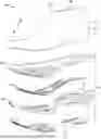
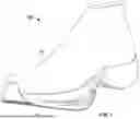


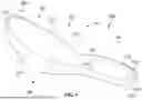
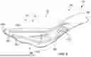
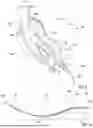
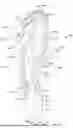


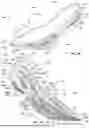


Sources:
- United States Patent and Trademark Office - verify current appl. status at the USPTO↗
Similar patent applications:
- » 20170150777
Articles of footwear and sole structures for articles of footwear - » 20170150778
Articles of Footwear and Sole Structures for Articles of Footwear - » 20210177092
Articles of footwear and sole structures for articles of footwear - » 20190142108
Articles of footwear and sole structures for articles of footwear - » 20090272008
Sole structures and articles of footwear including such sole structures - » 20250074036
POLYPROPYLENE-BASED OUTSOLE MATERIAL, FOOTWEAR SOLE STRUCTURE INCLUDING THE SAME, AND FOOTWAER ARTICLE INCLUDING THE FOOTWEAR SOLE STRUCTURE - » 20200229537
Sole structure for an article of footwear with undulating sole plate - » 20220117354
Sole structure for an article of footwear with undulating sole plate - » 20180338568
Sole structure for an article of footwear with undulating sole plate - » 20230309651
Sole structure for an article of footwear with undulating sole plate
Recent applications in this class:
- » 20250380769 2025-12-18
ARTICLE OF FOOTWEAR HAVING A SOLE PLATE - » 20250366566 2025-12-04
ADDITIVELY MANUFACTURED FOOTWEAR SOLES - » 20250359624 2025-11-27
ENERGY STORAGE AND RELEASE SOLE STRUCTURE - » 20250212993 2025-07-03
ADDITIVELY MANUFACTURED FOOTWEAR SOLES - » 20250204640 2025-06-26
SUPPORT ELEMENT FOR IMPROVED FOOT SHANK ALIGNMENT - » 20250127262 2025-04-24
SOLE FOR A SHOE - » 20250057280 2025-02-20
Exercise Shoes - » 20240215681 2024-07-04
ARTICLE OF FOOTWEAR INCLUDING AN INTEGRATED STABILITY MEMBER - » 20240188679 2024-06-13
FOOTWEAR INCLUDING A STABILIZING SOLE - » 20240164477 2024-05-23
Sole for a shoe