WIRE ROLLER, AND WIRE ROLLER ASSEMBLY
US20260138166A1
2026-05-21
18/949,131
2024-11-15
Smart Summary: A wire roller assembly is designed to help manage wire more easily. It has a central part called a hub that connects to a rotating device. The wire roller has a circular shape with a groove on the outside to hold the wire in place. There is also a hole in the roller that fits over the hub. This setup allows the wire roller to spin along with the device, making it simpler to use the wire. 🚀 TL;DR
Abstract:
A wire roller assembly is provided with a hub adapted to be mounted to a rotor of a rotary device. A wire roller is provided with an annular body with an outer surface, wherein a groove is formed in the outer surface sized to receive a wire, and wherein an aperture is formed in the body, sized to receive the hub mounted to the rotor of the rotary device. The wire roller is mounted to the hub.
Inventors:
- Scott DONALDSON 1 🇺🇸 Mundelein, IL, United States
- Guy BENNETT 1 🇺🇸 Mundelein, IL, United States
- Richard CLOR 1 🇺🇸 Mundelein, IL, United States
Applicant:
Interested in similar patents?
Get notified when new applications in this technology area are published.
Classification:
B21B1/18 » CPC main
Metal-rolling methods or mills for making semi-finished products of solid or profiled cross-section ; Sequence of operations in milling trains; Layout of rolling-mill plant, e.g. grouping of stands; Succession of passes or of sectional pass alternations for rolling wire rods, bars, merchant bars, rounds wire or material of like small cross-section in a continuous process
B21B27/024 » CPC further
Rolls, roll alloys or roll fabrication ; Lubricating, cooling or heating rolls while in use; Shape or construction of rolls Rolls for bars, rods, rounds, tubes, wire or the like
B21B27/02 IPC
Rolls, roll alloys or roll fabrication ; Lubricating, cooling or heating rolls while in use Shape or construction of rolls
Description
TECHNICAL FIELD
Various embodiments relate to wire rollers for manufacturing processes associated with wire.
BACKGROUND
The prior art has provided unitary, or one-piece, wire rollers that are mounted to rotors of rotary devices.
SUMMARY
According to an embodiment, a wire roller is provided with an annular body with an outer surface, wherein a groove is formed in the outer surface sized to receive a wire, and wherein an aperture is formed in the body, sized to receive a hub mounted to a rotor of a rotary device.
According to a further embodiment, the outer surface has an outer diameter.
According to another further embodiment, the aperture is a central aperture formed through the body.
According to an even further embodiment, the central aperture has an inner diameter sized to receive the hub.
According to another further embodiment, a fastener pattern is formed in the body to fasten the body to the hub.
According to another embodiment, a wire roller assembly is provided with a hub adapted to be mounted to a rotor of a rotary device. A wire roller is provided with an annular body with an outer surface, wherein a groove is formed in the outer surface sized to receive a wire, and wherein an aperture is formed in the body, sized to receive the hub mounted to the rotor of the rotary device. The wire roller is mounted to the hub.
According to a further embodiment, the wire roller is further defined as a first wire roller. The groove is further defined as a first groove sized to receive a first wire gauge. The wire roller assembly is further provided with a second roller with an annular body with an outer surface. A groove is formed in the outer surface, and is sized to receive a second wire gauge. An aperture is formed in the body, sized to receive the hub. The second wire gauge is different than the first wire gauge.
According to another further embodiment, the aperture is a central aperture formed through the body. The central aperture has an inner diameter sized to receive the hub. The hub has an outer diameter sized to be received in the inner diameter.
According to another further embodiment, a keyway is formed in the hub, sized to receive a key for alignment with the rotor.
According to another further embodiment, a fastener pattern is formed in the hub. The wire roller assembly is further provided with a plurality of fasteners sized to be received in the fastener pattern in the hub to fasten the hub to the rotor.
According to another further embodiment, an aperture is formed in the hub, sized to receive a portion of the rotor.
According to another further embodiment, a flange extends radially outward from the hub. A fastener pattern is formed in the flange, and a corresponding fastener pattern is formed in the body of the wire roller. A plurality of fasteners cooperates with the fastener pattern of the wire roller body and the flange to fasten the wire roller body to the flange of the hub.
According to another embodiment, a method is provided that installs an aperture of a wire roller onto a hub on a rotor of a rotary device. The wire roller is fastened to the hub.
According to a further embodiment, an aperture of the hub is installed on a portion of the rotor. The hub is fastened to the rotor.
According to an even further embodiment, a wire roller is removed from the rotor before installing the hub on the rotor.
According to another further embodiment, the wire roller is unfastened from the hub. The wire roller is removed from the hub. An aperture of a second wire roller is installed onto the hub. The wire roller is fastened to the hub.
According to another further embodiment, the wire roller is removed from a stored plurality of wire rollers upon shelving before installing the wire roller onto the hub.
According to another further embodiment, the rotor is rotated, and consequently, the hub, and the wire roller to feed wire to or from a machine.
According to another embodiment, a wire is formed from a method that installs an aperture of a wire roller onto a hub on a rotor of a rotary device. The wire roller is fastened to the hub. The rotor is rotated, and consequently, the hub and the wire roller are rotated to feed wire to or from the machine.
According to another embodiment, a wire roller assembly is provided with a hub with a body with an aperture sized to receive a distal end of a rotor of a rotary device. The hub has an outer diameter. The hub has a fastener pattern. A first plurality of fasteners is sized to be received in the fastener pattern in the hub to fasten the hub to the rotor. A flange extends radially outward from the hub for rotation with the hub. A fastener pattern is formed in the flange. A wire roller is provided with an annular body with an outer surface with an outer diameter. A groove is formed in the outer surface sized to receive a wire. A central aperture is formed through the body, with an inner diameter sized to receive the hub. A fastener pattern is formed in the body corresponding to the fastener pattern in the flange. A second plurality of fasteners is sized to be received in the fastener pattern in the wire roller to fasten the wire roller to the flange of the hub.
A system of one or more computers can be configured to perform particular operations or actions by virtue of having software, firmware, hardware, or a combination of them installed on the system that in operation causes or cause the system to perform the actions. One or more computer programs can be configured to perform particular operations or actions by virtue of including instructions that, when executed by data processing apparatus, cause the apparatus to perform the actions. One general embodiment includes a wire roller may include an annular body with an outer surface. Other embodiments include corresponding computer systems, apparatus, and computer programs recorded on one or more computer storage devices, each configured to perform the actions of the methods.
Various embodiments may include one or more of the following features. The wire roller may be embodied where the outer surface has an outer diameter. The aperture is a central aperture formed through the body. The central aperture has an inner diameter sized to receive the hub. A fastener pattern is formed in the body to fasten the body to the hub. A wire roller assembly may include: a hub adapted to be mounted to a rotor of a rotary device; and the wire roller mounted to the hub. The wire roller is further defined as a first wire roller; where the groove is further defined as a first groove sized to receive a first wire gauge; and where the wire roller assembly further may include a second roller may include an annular body with an outer surface, where a groove is formed in the outer surface sized to receive a second wire gauge, where an aperture is formed in the body, sized to receive the hub, and where the second wire gauge is different than the first wire gauge. The aperture is a central aperture formed through the body; where the central aperture has an inner diameter sized to receive the hub; and where the hub has an outer diameter sized to be received in the inner diameter. A keyway is formed in the hub, sized to receive a key for alignment with the rotor. A fastener pattern is formed in the hub; and where the wire roller assembly further may include a plurality of fasteners sized to be received in the fastener pattern in the hub to fasten the hub to the rotor. An aperture is formed in the hub, sized to receive a portion of the rotor. A fastener pattern is formed in the flange, and where a corresponding fastener pattern is formed in the body of the wire roller; and a plurality of fasteners cooperating with the fastener pattern of the wire roller body and the flange to fasten the wire roller body to the flange of the hub. Implementations of the described techniques may include hardware, a method or process, or computer software on a computer-accessible medium.
One general embodiment includes a method that includes installing an aperture of a wire roller onto a hub on a rotor of a rotary device. The method also includes fastening the wire roller to the hub. Other embodiments of this aspect include corresponding computer systems, apparatus, and computer programs recorded on one or more computer storage devices, each configured to perform the actions of the methods.
Implementations may include one or more of the following features. The method may include: installing an aperture of the hub on a portion of the rotor, and fastening the hub to the rotor. The method may include: removing a wire roller from the rotor before installing the hub on the rotor. The method may include: unfastening the wire roller from the hub, removing the wire roller from the hub, installing an aperture of a second wire roller onto the hub, and fastening the wire roller to the hub. The method may include: removing the wire roller from a stored plurality of wire rollers upon shelving before installing the wire roller onto the hub. The method may include: rotating the rotor, and consequently, the hub, and the wire roller to feed wire to or from a machine. A wire manufactured from the method. Implementations of the described techniques may include hardware, a method or process, or computer software on a computer-accessible medium.
One general embodiment provides the wire roller assembly, also including a hub that may include a body with an aperture sized to receive a distal end of a rotor of a rotary device, the hub having an outer diameter, the hub having a fastener pattern. The assembly also includes a first plurality of fasteners sized to be received in the fastener pattern in the hub to fasten the hub to the rotor. The assembly also includes a flange extending radially outward from the hub for rotation with the hub, where a fastener pattern is formed in the flange. The assembly also includes a wire roller may include an annular body with an outer surface with an outer diameter, where a groove is formed in the outer surface sized to receive a wire, and where a central aperture is formed through the body, with an inner diameter sized to receive the hub, where a fastener pattern is formed in the body corresponding to the fastener pattern in the flange. The assembly also includes a second plurality of fasteners sized to be received in the fastener pattern in the wire roller to fasten the wire roller to the flange of the hub. Other embodiments of this aspect include corresponding computer systems, apparatus, and computer programs recorded on one or more computer storage devices, each configured to perform the actions of the methods.
BRIEF DESCRIPTION OF THE DRAWINGS
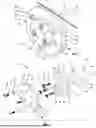
FIG. 1 is a perspective view of a wire roller assembly according to an embodiment;
FIG. 2 is an exploded perspective view of the wire roller assembly of FIG. 1;
FIG. 3 is a perspective view of a wire roller assembly according to another embodiment;
FIG. 4 is an exploded perspective view of the wire roller assembly of FIG. 3;
FIG. 5 is a flowchart of a method according to another embodiment; and
FIG. 6 is a flowchart of a method according to another embodiment.
DETAILED DESCRIPTION
As required, detailed embodiments of the present invention are disclosed herein; however, it is to be understood that the disclosed embodiments are merely exemplary of the invention that may be embodied in various and alternative forms. The figures are not necessarily to scale; some features may be exaggerated or minimized to show details of particular components. Therefore, specific structural and functional details disclosed herein are not to be interpreted as limiting, but merely as a representative basis for teaching one skilled in the art to variously employ embodiments according to the disclosure.
It will also be understood that, although the terms first, second, etc. are, in some instances, used herein to describe various elements in order of introduction, these elements should not be limited by these terms. These terms are only used to distinguish one element from another. For example, a first roller could be termed a second roller, and, similarly, a second roller could be termed a first roller, without departing from the scope of the various described embodiments. The first roller and the second roller are both rollers, but they are not the same roller.
The terminology used in the description of the various described embodiments herein is for the purpose of describing particular embodiments only and is not intended to be limiting. As used in the description of the various described embodiments and the appended claims, the singular forms “a”, “an” and “the” are intended to include the plural forms as well, unless the context clearly indicates otherwise. It will also be understood that the term “and/or” as used herein refers to and encompasses any and all possible combinations of one or more of the associated listed items. It will be further understood that the terms “includes,” “including,” “comprises,” and/or “comprising,” when used in this specification, specify the presence of stated features, integers, steps, operations, elements, and/or components, but do not preclude the presence or addition of one or more other features, integers, steps, operations, elements, components, and/or groups thereof.
As used herein, the term “if” is, optionally, construed to mean “when” or “upon” or “in response to determining” or “in response to detecting,” depending on the context. Similarly, the phrase “if it is determined” or “if [a stated condition or event] is detected” is, optionally, construed to mean “upon determining” or “in response to determining” or “upon detecting [the stated condition or event]” or “in response to detecting [the stated condition or event],” depending on the context.
Wires are conductive materials used to transmit electrical power or signals. Wires come in various types, each designed for specific functions. One such example is copper wire, which is commonly used for electrical wiring due to its high conductivity. Copper wire is utilized for grounding an electrical circuit. Enamel-coated copper wire is used in electromagnets and motors.
Another example is aluminum wire, which is used in overhead power lines and some residential wiring. Aluminum wire is lightweight and cost-effective, but less conductive than copper.
Another wire example is twisted pair wire, which is primarily used in telecommunications and networking. A further example includes unshielded twisted pair (UTP) wire, which is common in local area networks (LANs). Another further example is shielded twisted pair (STP) wire, which offers protection against electromagnetic interference.
Yet another wire example is coaxial cable, often used for cable television and internet connections. Coaxial cable consists of a central conductor, an insulating layer, a metallic shield, and an outer insulating layer.
Fiber optic cable is yet another example, which is utilized to transmit data as light signals over long distances. Single-mode fiber is employed for long-distance communication. Multi-mode fiber is useful for shorter distances with higher data rates.
Speaker wire is another wire example to connect speakers to amplifiers or receivers in audio systems. Speaker wire is typically made of copper with varying gauges depending on distance and power needs.
Yet another example includes electrical wiring, which is often used in residential wiring for powering household applications. Electrical wiring may also be used in conduit and for higher temperature applications.
Another example includes thermocouple wire that is employed to measure temperature by producing a voltage based on temperature differences. Different alloys of thermocouple wire are provided for various temperature ranges and environments.
Another wire example includes ground wire, which provides a safe path for electricity to ground, to mitigate inadvertent shorts or high thermal events. Ground wire is often manufactured of copper or aluminum.
Magnet wire is a wire example that is employed in motors and transformers, and is typically enamel-coated to insulate the wire.
When selecting a wire, application of the wire is one consideration, as discussed above with examples of wires and associated applications. Conductor material is another consideration. For example, copper and aluminum can be compared and contrasted for conductivity and weight. Gauge selection is another consideration; thickness of the wire affects current capacity and resistance. Insulation type is another consideration, which is relevant for avoiding shorted circuits and often selected by application (e.g., temperature, moisture resistance).
Structural wire refers to a type of wire that is specifically designed and engineered for use in structural applications, providing support and stability in various construction and engineering projects. It is commonly used in reinforcement, suspension systems, and other load-bearing applications. Structural wire is typically made from high-strength steel, though it can also be made from other materials like stainless steel or aluminum, depending on the application and environmental conditions. Structural wire is designed to have high tensile strength to withstand significant loads and stresses, making it suitable for structural applications. Structural wire is manufactured in various diameters and gauges, allowing it to be tailored for specific uses, from fine wire used in detailed applications to thicker wire for heavy-duty support. Structural wire may have various surface treatments (like galvanization or coating) to enhance corrosion resistance and durability in harsh environments.
Structural wire is often used for reinforcement, for example, use in concrete structures, such as beams, slabs, and foundations, to provide additional tensile strength. Structural wire may be utilized as suspension cables, which may be employed in bridges and other structures where high tensile strength is useful for stability and load distribution. Another use of structural wire is fencing, wherein the wire is used in structural fencing applications where durability and strength are optimized. Industrial applications of structural wire are common in machinery, scaffolding, and other construction-related uses. Structural wire is also utilized in architectural features, such as design elements like cable-stayed structures and artistic installations, providing both support and aesthetic appeal.
Structural wire is a useful component in various engineering and construction applications, known for its strength and versatility. Its ability to provide support and reinforcement makes it applicable for stability and safety of structures.
A wire roller machine is equipment used to process and shape wire for various applications. These machines can perform different functions, including rolling, bending, coiling, straightening, or conveying wire. Wire roller machines can flatten or roll wire into various shapes and sizes, making it easier to work with in subsequent manufacturing processes. These machines can bend wire at precise angles, which is advantageous for creating components in construction, automotive, and manufacturing sectors. Some wire roller machines are designed to coil wire into specific diameters for storage or transport, which is common in electrical and industrial applications. Wire roller machines can also straighten coiled or bent wire to ensure uniformity and ease of use in fabrication. Many models of wire roller machines come equipped with cutting capabilities, allowing for quick and accurate lengths to be achieved during processing.
Wire roller machines include manual wire rollers, which are operated by hand, and are suitable for small-scale operations or crafts. Electric wire roller machines are automated and are designed for larger-scale production, providing faster and more consistent results. Computer Numerical Control (CNC) wire bending machines offer high precision for complex bending and shaping tasks.
Wire roller machines are often utilized in manufacturing, wherein these machines are used in producing wire components for various industries, including automotive, aerospace, and electronics. These machines are also employed in construction, wherein wire roller machine are employed to create reinforcing rods and mesh for concrete. Wire roller machines are also employed for jewelry making, wherein smaller wire rollers are used in crafting and shaping wire for artistic applications.
Wire roller machines are versatile tools for shaping and processing wire in numerous industries. The ability of these machines to perform multiple functions enhances efficiency and precision in wire manufacturing and fabrication.
FIG. 1 illustrates a roller assembly 20 installed on a rotor 22 of a rotary device 24, according to an embodiment. The rotary device 24 includes a source of rotary motion to rotate the rotor 22, such as a motor and a power source, as is known in the art. The depicted roller assembly 20 is utilized to feed wire 26 into a cold forming machine, such as a cold header machine, or a hemming machine. The roller assembly 20 may be employed alone, as illustrated in FIG. 1, according to some embodiments. The roller assembly 20 may be employed in combination with one or more roller assemblies 20, according to other embodiments. According to another embodiment, the roller assembly 20 may cooperate with a second roller assembly 20 (not shown) to collectively rotate, in counter rotation, and to collectively cooperate with the wire 26. The rotary device 24 may be a separate device from the associated machine, or may be a subassembly of the associated machine. Any variation of wire 26 and any rotary device 24 may be utilized according to various embodiments.
FIG. 2 is an exploded view of the roller assembly 20 and the rotor 22 of the rotary device 24. In FIG. 2, the rotor 22 includes a shaft 28 which is driven by the rotary device 24 for rotation. A distal end 30 of the rotor 22 provides a hub 30 for installation of the roller assembly 20. A portion 32 of the rotor 22 is provided for positioning of the wire roller assembly 20. In the depicted embodiment, the hub 30 includes a pin or a pilot 32 extending from a mounting surface 34 on the distal end 30 of the rotor 22. The mounting surface 34 provides a contact surface for the wire roller assembly 20 for positioning of the wire roller assembly 20 in an axial direction of the rotor 22. The pilot 32 provides for positioning of the wire roller assembly 20 for concentricity with the rotor 22 within suitable manufacturing tolerances. A fastener pattern 36 is formed into the mounting surface 34 of the rotor 22. According to some embodiments, the fastener pattern 36 is a hole pattern 36, or an aperture array 36. According to the depicted embodiment, the fastener pattern 36 is an array of threaded apertures 36 for receipt of threaded fasteners.
The prior art provided unitary, or one-piece, wire rollers that are mounted directly on the pilot 32 and fastened to the mounting surface 34 with fasteners in the apertures 36. In larger applications where steel rollers are warranted, such wire rollers exceed twelve and a half pounds, and in some applications, the prior art wire rollers obtain weights of thirty-six pounds, or greater.
Wire rollers are changed often. For example, wire rollers may be changed due to wear. Additionally, wire rollers may be sized for wire of various gauges or diameters, and may be changed out for handling, forming, or feeding wires of various gauges. Such changeovers may require significant effort due to the weight of the rollers.
Due to frequent changeover of the wire rollers, an inventory of the wire rollers is often stored to support replacement or variations of wire gauges. Such storage requires significant volume and structure, such as shelving to store and organize the wire rollers.
The wire roller assembly 20 includes an adaptor hub 38 that is installed directly to the rotor 22, and a separate wire roller 40 that is installed to the hub 38. By providing the wire roller assembly 20 with multiple components 38, 40, the weight of the assembly 20 is divided between the multiple components 38, 40, thereby reducing the effort associated with installation or removal of each component 38, 40. In other words, a reduced weight of individual components 38, 40, reduces an effort on an operator during installation in comparison to installation of a unitary wire roller of the prior art.
Additionally, the adaptor hub 38 is designed as universal to a variety of applicable wire rollers 40. Therefore, the adaptor hub 38 can be installed on the rotor 22 and maintained on the rotor 22, while various wire rollers 40 are installed and removed from the adaptor hub 38. Therefore, a significant weight reduction is provided when changing out the wire roller 40 to install another wire roller 40. Additionally, by reusing the adaptor hub 38, less material is scrapped or recycled when a wire roller 40 is removed due to wear. Likewise, less material is required when manufacturing a replacement wire roller 40. The material reduction consequently provides a cost reduction for each wire roller 40 replacement.
The adaptor hub 38 includes a first mating surface 42 to engage the rotor mounting surface 34. The adaptor hub 38 includes a hub body 44 extending axially away from the first mating surface 42. An aperture 46 is formed into, and through the hub body 44. The aperture 46 is formed centrally through the hub body 44 and is sized to receive the rotor pilot 32 for positioning of the hub 38 centrally relative to an axis of rotation of the rotor 22. The aperture 46 may be sized to receive the pilot 32 as a slip fit, an interference fit, or a press fit, depending on the permissible manufacturing tolerances of the application.
A first fastener pattern 48 is provided in the hub body 44 and aligned with the rotor fastener pattern 36. In the depicted embodiment, the fastener pattern 48 includes an array of apertures 48 formed through the hub body 44 and spaced about the central aperture 46. According to one embodiment, the hub first fastener pattern 48 includes a plurality of counterbored apertures 48. The wire roller assembly 20 is provided with a plurality of first fasteners 50 that are sized to be received in the hub first fastener pattern 48 and extend through the hub body 44 into threaded engagement with the rotor fastener pattern 36 to fasten the hub adaptor 38 to the rotor 22. According to an embodiment, the first fasteners 50 are an array of socket head cap screws 50, each with a socket head 52 sized to be received within the counterbored holes 48 to a limited depth. The socket head cap screws 50 each include a threaded shank 54 sized to extend through the counterbored holes 48 and into threaded engagement with the threaded apertures 36 in the rotor 22.
The adaptor hub body 44 includes an outer diameter that is sized to receive the wire roller 40. The hub body 44 is also sized to position the wire roller 40 for concentricity within manufacturing tolerances with the adaptor hub 38 and the rotor 22 for rotation with the adaptor hub 38 and the rotor 22.
The adaptor hub 38 includes an annular flange 56 provided at a proximal end of the hub 38 and extending radially outward from the hub body 44. The flange 56 may provide at least a portion of the first mounting surface 42. The flange 56 also provides a second mating surface 58 of the hub 38. The second mating surface 58 is opposed from the first mating surface 42 and spaced axially from the first mating surface 42. The second mating surface 58 is sized to receive the wire roller 40 for axial positioning of the wire roller 40.
A second fastener pattern 60 of the adaptor hub 38 is provided on the flange 56 about the hub body 44. According to some embodiments, the fastener pattern 60 is a fastener array, and according to the depicted embodiment, the fastener pattern 60 is an array of apertures 60. According to at least one embodiment, each aperture 60 of the array 60 is threaded.
With reference again to FIGS. 1 and 2, the wire roller 40 is provided with an annular, or disc-shaped, body 62. The annular body 62 includes a mating surface 64 to engage the second hub mating surface 58 for axial positioning of the wire roller 40 relative to the hub 38, and consequently, the rotor 22. An aperture 66 is formed in, or through the body 62, and is sized to receive the hub body 44. The aperture 66 is positioned as a central aperture 66, and is sized with an inner diameter that is sized relative to the hub body 62 for a slip fit, press fit, or interference fit upon the hub body 62. The hub body 62 positions the wire roller 40 radially for concentric rotation with the adaptor hub 38 and the rotor 22.
A fastener pattern 68 is provided on the roller body 62. In one embodiment, the fastener pattern 68 is an array of apertures 68 formed through the body 62, and oriented about the central aperture 66. The array of apertures 68 are provided as through holes 68. The array of apertures 68 is positioned to align with the second fastener pattern 60 of the adaptor hub 38. In the depicted embodiment, the array of apertures 68 includes a greater quantity (nine, for example) of apertures 68 than a quantity (three, for another example) of the apertures 60 of the adaptor hub 38 to permit the wire roller 40 to align with the second fastener pattern 60 of the adaptor hub 38 at various incremental rotary positions.
A second plurality of fasteners 70 is provided to fasten the wire roller 40 to the adaptor hub 38. According to an embodiment, the fasteners 70 are socket head cap screws 70. A plurality of washers 72 are provided to be received upon shanks 74 of the cap screws 70. The washers 72 limit friction between heads 76 of the screws 70 and the body 62 of the wire roller 40. The shanks 74 of the screws 70 extend through the apertures 68 of the wire roller 40 and are received in threaded engagement in the threaded apertures 60 of the flange 56 of the adaptor hub 38.
The wire roller 40 includes an outer surface 78 with an outer diameter to operate as the roller 40. A peripheral groove 80 is formed into the outer surface 78 to a limited depth to receive the wire 26 and to guide the wire 26 for translation relative to the wire roller 40. Rotation of the rotor 22, rotates the adaptor hub 38 and the wire roller 40 to convey the wire 26 along the groove 80 in the wire roller 40. Although one groove 80 is depicted, any suitable number of grooves 80 may be employed for one or more wires 26. The groove 80 is sized for the applicable wire 26. Various wire rollers 40 are interchangeable with the wire roller 40 for replacement due to wear. Various wire rollers 40 are interchangeable with the wire roller 40 with grooves 80 of varying sizes to roll wires 26 of various diameters or gauges.
According to another embodiment, a second roller assembly 20 (not shown) is provided with the outer surface 78 spaced apart from the outer surface 78 of the depicted roller assembly 20, such that the peripheral groove 80 of the second roller assembly 20 cooperates with the peripheral groove 80 of the depicted roller assembly 20. The depicted roller assembly 20 and the second roller assembly 20 may be spaced such that the cooperating peripheral grooves 80 provide compression to the wire 26 to grip and translate the wire 26. Under this cooperation, the roller assemblies 120 are counter-rotated such that if the depicted roller assembly 20 is rotated clockwise, then the second roller assembly 20 is rotated counter-clockwise. According to another embodiment, the roller assemblies 20 may be spaced a distance to collectively perform a shaping or forming operation upon the wire 26 as the wire 26 is translated by the roller assemblies 20.
By reducing the weight and size of the interchangeable wire rollers 40, ease in installation and removal is provided. Additionally, costs in replacement are minimized. Additionally, less material is scrapped or recycled. The reduced weight and overall size optimize storage of the replacement wire rollers 40. For example, existing shelving can be utilized to store more wire rollers 40 in comparison to the prior art due to reduced weight and volume.
The wire roller assembly 20 reduces volume in comparison to prior art wire rollers due to a reduced thickness of the wire roller 40. Consequently, the wire roller assembly 20 reduces weight in comparison to a convention wire roller. The reduction in the overall weight reduces energy consumed by the wire roller machine when driving the wire roller assembly 20 to feed the wire 26.
FIG. 3 illustrates a roller assembly 120 installed on a rotor 122 of a rotary device 124, according to an embodiment. FIG. 4 is an exploded view of the roller assembly 120 and reveals the rotor 122 of the rotary device 124. The rotary device 124 includes a source of rotary motion to rotate the rotor 122. The depicted roller assembly 120 is utilized to feed wire 126 into a cold forming machine, such as a cold header machine. The roller assembly 120 may be employed alone, as illustrated in FIG. 3, according to some embodiments. The roller assembly 120 may be employed in combination with one or more roller assemblies 120, according to other embodiments. According to another embodiment, the roller assembly 120 may cooperate with a second roller assembly 120 (not shown) to collectively rotate, in counter rotation, and to collectively cooperate with the wire 126. The rotary device 124 may be a separate device from the associated machine, or may be a subassembly of the associated machine. Any variation of wire 126 and any rotary device 124 may be utilized according to various embodiments.
In FIG. 4, the rotor 122 includes a shaft 128 which is driven by the rotary device 124 for rotation. A distal end 130 of the rotor 122 provides a hub 132 for installation of the roller assembly 120. The hub 132 of the rotor 122 is provided for positioning of the wire roller assembly 120. In the depicted embodiment, the hub 132 extends from a mounting surface 134 of the rotor 122. The mounting surface 134 is provided on the hub 132 to provide a contact surface for the wire roller assembly 120 for positioning of the wire roller assembly 120 in an axial direction of the rotor 122. The hub 132 provides for positioning of the wire roller assembly 120 for concentricity with the rotor 122 within suitable manufacturing tolerances.
A first fastener pattern 136 is formed into the hub 132 of the rotor 122. According to some embodiments, the first fastener pattern 136 is a hole pattern 136, or an aperture array 136. According to the depicted embodiment, the first fastener pattern 136 is an array of threaded apertures 136 for receipt of threaded fasteners. A keyway 138 is formed in the hub 132 and the rotor 122 for receipt of a key 142 for angular position of the wire roller assembly 120. A second fastener pattern 140 is formed into the hub 132 of the rotor 122. According to some embodiments, the second fastener pattern 140 is a hole pattern 140, or an aperture array 140. According to the depicted embodiment, the second fastener pattern 140 is a central threaded aperture 140 for receipt of a threaded fastener.
The wire roller assembly 120 includes an adaptor hub 144 that is installed directly to the rotor 122, and a separate wire roller 146 that is installed to the hub 144. By providing the wire roller assembly 120 with multiple components 144, 146, the weight of the assembly 120 is divided between the multiple components 144, 146, thereby reducing the effort associated with installation or removal of each component 144, 146. In other words, a reduced weight of individual components 144, 146, reduces an effort on an operator during installation in comparison to installation of a unitary wire roller of the prior art.
Additionally, the adaptor hub 144 is designed as universal to a variety of applicable wire rollers 146. Therefore, the adaptor hub 144 can be installed on the rotor 122 and maintained on the rotor 122, while various wire rollers 146 are installed and removed from the adaptor hub 144. Therefore, a significant weight reduction is provided when changing out the wire roller 146 to install another wire roller 146. Additionally, by reusing the adaptor hub 144, less material is scrapped or recycled when a wire roller 146 is removed due to wear. Likewise, less material is required when manufacturing a replacement wire roller 146. The material reduction consequently provides a cost reduction for each wire roller 146 replacement.
The adaptor hub 144 includes a first mating surface 148 to engage the rotor mounting surface 134. The adaptor hub 144 includes a hub body 150 extending axially away from the rotor 122. An aperture 152 is formed into the hub body 150 to a blind depth. The aperture 152 is formed centrally into the hub body 150 and is sized to receive the rotor hub 132 for positioning of the hub 144 centrally relative to an axis of rotation of the rotor 122. The aperture 152 may be sized to receive the hub 132 as a slip fit, an interference fit, or a press fit, depending on the permissible manufacturing tolerances of the application. Additionally, a keyway 154 is formed into the hub body 150. The keyway 154 is sized to receive the key 142. The keyway 154 is also formed to a blind depth to retain the key 142 within the keyways 138, 154 of the rotor 122 and the adaptor hub 144. The key 142 and keyways 138, 154 cooperate for alignment of a rotary position of the adaptor hub 150 relative to the rotor 122.
A first fastener pattern 156 is provided in the hub body 150 and aligned with the rotor first fastener pattern 136. In the depicted embodiment, the fastener pattern 156 includes an array of apertures 156 formed through the hub body 150 and aligned to intersect the central aperture 152. According to one embodiment, the hub first fastener pattern 156 includes a plurality of counterbored apertures 156. The wire roller assembly 120 is provided with a plurality of first fasteners 158 that are sized to be received in the hub first fastener pattern 156 and extend through the hub body 150 and the central aperture 152 into threaded engagement with the rotor fastener pattern 136 to fasten the hub adaptor 144 to the rotor 122. According to an embodiment, the first fasteners 158 are an array of socket head cap screws 158, each with a socket head 160 sized to be received within the counterbored holes 156 to a limited depth. The socket head cap screws 158 each include a threaded shank 162 sized to extend through the counterbored holes 156, through the central aperture 152 and into threaded engagement with the threaded apertures 136 in the rotor 122.
A second fastener pattern 164 is formed in the hub body 150 and spaced about the central aperture 152 for alignment with the rotor mounting surface 134. In the depicted embodiment, the second fastener pattern 164 includes an array of apertures 164 formed through the hub body 150. According to one embodiment, the second fastener pattern 164 includes a plurality of threaded apertures 164. The wire roller assembly 120 is provided with a plurality of second threaded fasteners 166 sized to be received within the plurality of threaded apertures 164. According to the depicted embodiment, the second threaded fasteners 166 are set screws 166 sized to be installed in the threaded apertures 164 to extend through the threaded apertures 164. The set screws 166 are employed to adjust a position of the adaptor plate 144 relative to the mounting surface 134 to space the mounting surface 148 of the adaptor plate 144 away from the mounting surface 134 for axial adjustment of the adaptor hub 144 relative to the rotor 122.
A third fastener pattern 168 is formed in the hub body 150 and oriented centrally in the hub body 150. In the depicted embodiment, the third fastener pattern 168 includes a through aperture 168 formed through the hub body 150 intersecting the central aperture 152 and aligned with the central threaded aperture 140 in the hub 132 of the rotor 122. The wire roller assembly 120 includes a third fastener 170. The third fastener 170, in one embodiment, is provided as a hex head bolt 170 with a threaded shank 172 sized to extend through the hub central aperture 168 and into threaded engagement with the central threaded aperture 140 in the hub 132 of the rotor 122. The third fastener 170 extends through a biasing member, such as a compression spring 174, oriented between a pair of washers 176. A fastener head 178 of the hex bolt 170 engages one of the washers 176 to compress the spring 174 against the other washer 176 upon the hub body 150. Tightening of the hex bolt 170 compresses the spring 174 to apply a force upon the hub body 150 to bias the hub body 150, and consequently, the set screws 166 into engagement with the mounting surface 134 of the rotor 122.
The adaptor hub body 150 includes an outer diameter that is sized to receive the wire roller 146. The hub body 150 is also sized to position the wire roller 146 for concentricity within manufacturing tolerances with the adaptor hub 144 and the rotor 122 for rotation with the adaptor hub 144 and the rotor 122.
The adaptor hub 144 includes an annular flange 180 provided at a proximal end of the hub 144 and extending radially outward from the hub body 150. The flange 180 may provide at least a portion of the first mounting surface 148. The flange 180 also provides a second mating surface 182 of the hub 144. The second mating surface 182 is opposed from the first mating surface 148 and spaced axially from the first mating surface 148. The second mating surface 182 is sized to receive the wire roller 146 for axial positioning of the wire roller 146.
A fourth fastener pattern 184 of the adaptor hub 144 is provided on the flange 180 about the hub body 150. According to some embodiments, the fastener pattern 184 is a fastener array, and according to the depicted embodiment, the fastener pattern 184 is an array of apertures 184. According to at least one embodiment, each aperture 184 of the array 184 is threaded.
With reference again to FIGS. 3 and 4, the wire roller 146 is provided with an annular, or disc-shaped, body 186. The annular body 186 includes a mating surface 188 to engage the hub second mating surface 182 for axial positioning of the wire roller 146 relative to the hub 144, and consequently, the rotor 122. An aperture 190 is formed in, or through the body 186, and is sized to receive the hub body 150. The aperture 190 is positioned as a central aperture 190, and is sized with an inner diameter that is sized relative to the hub body 186 for a slip fit, press fit, or interference fit upon the hub body 186. The hub body 186 positions the wire roller 146 radially for concentric rotation with the adaptor hub 144 and the rotor 122.
A fastener pattern 192 is provided on the roller body 186. In one embodiment, the fastener pattern 192 is an array of apertures 192 formed through the body 186, and oriented about the central aperture 190. The array of apertures 192 are provided as through holes 192. The array of apertures 192 is positioned to align with the fourth fastener pattern 184 of the adaptor hub 144. In the depicted embodiment, the array of apertures 192 includes a greater quantity (nine, for example) of apertures 192 than a quantity (three, for another example) of the apertures 184 of the adaptor hub 144 to permit the wire roller 146 to align with the fourth fastener pattern 184 of the adaptor hub 144 at various incremental rotary positions.
A second plurality of fasteners 194 is provided to fasten the wire roller 146 to the adaptor hub 144. According to an embodiment, the fasteners 194 are socket head cap screws 194. A plurality of washers 196 are provided to be received upon shanks 198 of the cap screws 194. The washers 196 limit friction between heads 200 of the screws 194 and the body 186 of the wire roller 146. The shanks 198 of the screws 194 extend through the apertures 192 of the wire roller 146 and are received in threaded engagement in the threaded apertures 184 of the flange 180 of the adaptor hub 144.
The wire roller 146 includes an outer surface 202 with an outer diameter to operate as the roller 146. A peripheral groove 204 is formed into the outer surface 202 to a limited depth to receive the wire 126 and to guide the wire 126 for translation relative to the wire roller 146. Rotation of the rotor 122, rotates the adaptor hub 144 and the wire roller 146 to convey the wire 126 along the groove 204 in the wire roller 146. Although one groove 204 is depicted, any suitable number of grooves 204 may be employed for one or more wires 126. The groove 204 is sized for the applicable wire 126. Various wire rollers 146 are interchangeable with the wire roller 146 for replacement due to wear. Various wire rollers 146 are interchangeable with the wire roller 146 with grooves 204 of varying sizes to roll wires 126 of various diameters or gauges.
According to another embodiment, a second roller assembly 120 (not shown) is provided with the outer surface 202 spaced apart from the outer surface 202 of the depicted roller assembly 120, such that the peripheral groove 204 of the second roller assembly 120 cooperates with the peripheral groove 204 of the depicted roller assembly 120. The depicted roller assembly 120 and the second roller assembly 120 may be spaced such that the cooperating peripheral grooves 204 provide compression to the wire 126 to grip and translate the wire 126. Under this cooperation, the roller assemblies 120 are counter-rotated such that if the depicted roller assembly 120 is rotated clockwise, then the second roller assembly 120 is rotated counter-clockwise. According to another embodiment, the roller assemblies 120 may be spaced a distance to collectively perform a shaping or forming operation upon the wire 126 as the wire 126 is translated by the roller assemblies 120.
By reducing the weight and size of the interchangeable wire rollers 146, ease in installation and removal is provided. Additionally, costs in replacement are minimized. Additionally, less material is scrapped or recycled. The reduced weight and overall size optimize storage of the replacement wire rollers 146. For example, existing shelving can be utilized to store more wire rollers 146 in comparison to the prior art due to reduced weight and volume.
The wire roller assembly 120 reduces volume in comparison to prior art wire rollers due to a reduced thickness of the wire roller 146. Consequently, the wire roller assembly 120 reduces weight in comparison to a convention wire roller. The reduction in the overall weight reduces energy consumed by the wire roller machine when driving the wire roller assembly 120 to feed the wire 126.
FIG. 5 illustrates a method for installing a roller assembly 20, 120 is provided, according to an embodiment. At step 302, a wire roller is removed from a rotor 22, 122 of a rotary device 24, 124. According to an embodiment, the removed wire roller is a prior art unitary wire roller. Under this example, the method of FIG. 5 is a method for retrofitting prior art equipment with the roller assembly 20, 120.
At step 304, an aperture 46, 152 of a hub 38, 144 is installed on a portion 32, 132 of the rotor 22, 122. At step 306, the hub 38, 144 is fastened to the rotor 22, 122. At step 308, a wire roller 40, 146 is removed from storage with a plurality of other wire rollers 40, 146. At step 310, an aperture 66, 190 of the wire roller 40, 146 is installed onto the hub 38, 144. At step 312, the wire roller 40, 146 is fastened to the hub 38, 144. After step 312, the rotary device 24, 124 is retrofitted with the wire roller assembly 20, 120. Next, at step 314, the rotor 22, 122 is rotated by the rotary device 24, 124, thereby rotating the hub 38, 144 and the wire roller 40, 146, to feed wire 26, 126 to or from a machine.
FIG. 6 illustrates a method for changing one of the wire rollers 40, 146 due to wear, or to roll a wire 26, 126 of a different gauge. In step 402, the wire roller 40, 146 is unfastened from the hub 38, 144. Then, at step 404, the wire roller 40, 146 is removed from the hub 38, 144. At step 406, an aperture 66, 190 of the wire roller 40, 146 is installed onto the hub 38, 144. At step 408, the wire roller 40, 146 is fastened to the hub 38, 144. Next, at step 410, the rotor 22, 122 is rotated by the rotary device 24, 124, thereby rotating the hub 38, 144 and the wire roller 40, 146, to feed wire 26, 126 to or from the machine.
While various embodiments are described above, it is not intended that these embodiments describe all possible forms of the invention. Rather, the words used in the specification are words of description rather than limitation, and it is understood that various changes may be made without departing from the spirit and scope of the invention. Additionally, the features of various implementing embodiments may be combined to form further embodiments of the invention.
Claims
What is claimed is:1. A wire roller comprising an annular body with an outer surface, wherein a groove is formed in the outer surface sized to receive a wire, and wherein an aperture is formed in the body, sized to receive a hub mounted to a rotor of a rotary device.
2. The wire roller of claim 1, wherein the outer surface has an outer diameter.
3. The wire roller of claim 1, wherein the aperture is a central aperture formed through the body.
4. The wire roller of claim 3, wherein the central aperture has an inner diameter sized to receive the hub.
5. The wire roller of claim 1, wherein a fastener pattern is formed in the body to fasten the body to the hub.
6. A wire roller assembly comprising:
a hub adapted to be mounted to a rotor of a rotary device; and
the wire roller according to claim 1, mounted to the hub.
7. The wire roller assembly of claim 6, wherein the wire roller is further defined as a first wire roller;
wherein the groove is further defined as a first groove sized to receive a first wire gauge; and
wherein the wire roller assembly further comprises a second roller comprising an annular body with an outer surface, wherein a groove is formed in the outer surface sized to receive a second wire gauge, wherein an aperture is formed in the body, sized to receive the hub, and wherein the second wire gauge is different than the first wire gauge.
8. The wire roller assembly of claim 6, wherein the aperture is a central aperture formed through the body;
wherein the central aperture has an inner diameter sized to receive the hub; and
wherein the hub has an outer diameter sized to be received in the inner diameter.
9. The wire roller assembly of claim 6, wherein a keyway is formed in the hub, sized to receive a key for alignment with the rotor.
10. The wire roller assembly of claim 6, wherein a fastener pattern is formed in the hub; and
wherein the wire roller assembly further comprises a plurality of fasteners sized to be received in the fastener pattern in the hub to fasten the hub to the rotor.
11. The wire roller assembly of claim 6, wherein an aperture is formed in the hub, sized to receive a portion of the rotor.
12. The wire roller assembly of claim 6, further comprising:
a flange extending radially outward from the hub, wherein a fastener pattern is formed in the flange, and wherein a corresponding fastener pattern is formed in the body of the wire roller; and
a plurality of fasteners cooperating with the fastener pattern of the wire roller body and the flange to fasten the wire roller body to the flange of the hub.
13. A method comprising:
installing an aperture of a wire roller onto a hub on a rotor of a rotary device; and
fastening the wire roller to the hub.
14. The method of claim 13, further comprising:
installing an aperture of the hub on a portion of the rotor; and
fastening the hub to the rotor.
15. The method of claim 14, further comprising:
removing a wire roller from the rotor before installing the hub on the rotor.
16. The method of claim 13, further comprising:
unfastening the wire roller from the hub;
removing the wire roller from the hub;
installing an aperture of a second wire roller onto the hub; and
fastening the wire roller to the hub.
17. The method of claim 13, further comprising:
removing the wire roller from a stored plurality of wire rollers upon shelving before installing the wire roller onto the hub.
18. The method of claim 13, further comprising:
rotating the rotor, and consequently, the hub and the wire roller, to feed wire to or from a machine.
19. A wire manufactured from the method of claim 18.
20. A wire roller assembly comprising:
a hub comprising a body with an aperture sized to receive a distal end of a rotor of a rotary device, the hub having an outer diameter, the hub having a fastener pattern;
a first plurality of fasteners sized to be received in the fastener pattern in the hub to fasten the hub to the rotor;
a flange extending radially outward from the hub for rotation with the hub, wherein a fastener pattern is formed in the flange;
a wire roller comprising an annular body with an outer surface with an outer diameter, wherein a groove is formed in the outer surface sized to receive a wire, and wherein a central aperture is formed through the body, with an inner diameter sized to receive the hub, wherein a fastener pattern is formed in the body corresponding to the fastener pattern in the flange; and
a second plurality of fasteners sized to be received in the fastener pattern in the wire roller to fasten the wire roller to the flange of the hub.
Images & Drawings included:


Sources:
- United States Patent and Trademark Office - verify current appl. status at the USPTO↗
Recent applications in this class:
- » 20250178052 2025-06-05
ROLL BENDING MACHINE AND ROLL BENDING METHOD - » 20240390962 2024-11-28
ROLLING APPARATUS, PLANT AND METHOD - » 20240299996 2024-09-12
METHOD FOR SHAPING WIRE MATERIAL AND WIRE MATERIAL SHAPING DEVICE - » 20230201898 2023-06-29
Metal material processing machine - » 20220324003 2022-10-13
Apparatus and methods using the apparatus for treating metal wire - » 20210229146 2021-07-29
Frequency-dependent distribution of manipulated variables for changing the rolling stock cross section in a roll train - » 20200282439 2020-09-10
Method to adjust the drawing action on a bar and corresponding device - » 20180200767 2018-07-19
Method for rolling metal wire or rod with assistance of combined static magnetic field - » 20140338413 2014-11-20
WIRE-ROD AND THE LIKE HOT-ROLLING MACHINE - » 20140041432 2014-02-13
HOT-ROLLING MACHINE FOR WIRE-ROD AND THE LIKE