PHOTOVOLTAIC SOLAR TRACKER ASSEMBLY
US20260142476A1
2026-05-21
18/280,263
2023-08-09
Smart Summary: A photovoltaic solar tracker assembly helps collect solar energy more efficiently. It has solar trackers that follow the sun, a rechargeable power supply to keep them running, and a system to recharge the power supply. Supercapacitors are used as part of the power supply, which allows for better performance in cold temperatures without needing heaters. This design increases the lifespan of the components and makes them smaller. Overall, it improves the effectiveness of solar energy collection. 🚀 TL;DR
Abstract:
An assembly includes one or more photovoltaic solar trackers; a rechargeable power supply system, including power supply elements to power the tracker or trackers; a charging system, to recharge the power elements; and a tracker controller. The assembly stands out for including one or more supercapacitors as power supply elements. The invention makes it possible to arrange the power supply elements at low temperatures without the need for heaters, increase their useful life and reduce their size.
Inventors:
- Samir CHAOUKI ALMAGRO 3 🇪🇸 Molina de Segura, Spain
- Alejandro CARDONA VÉLEZ 1 🇪🇸 Molina de Segura, Spain
- Ignacio MELÓN MENÉNDEZ 1 🇪🇸 Molina de Segura, Spain
- Juan José PUERTA MUÑOZ 1 🇪🇸 Molina de Segura, Spain
- Francisco Javier TORRANO CARRILLO 1
- Marta GARCÍA VIVANCOS 1 🇪🇸 Molina de Segura, Spain
Assignee:
- SOLTEC INNOVATIONS, S.L. 25 🇪🇸 Molina de Segura, Spain
Applicant:
Interested in similar patents?
Get notified when new applications in this technology area are published.
Classification:
G05D3/105 » CPC further
Control of position or direction without using feedback Solar tracker
H02J7/345 » CPC further
Circuit arrangements for charging or depolarising batteries or for supplying loads from batteries; Parallel operation in networks using both storage and other dc sources, e.g. providing buffering using capacitors as storage or buffering devices
H02S10/20 » CPC further
PV power plants; Combinations of PV energy systems with other systems for the generation of electric power Systems characterised by their energy storage means
H02S20/32 » CPC further
Supporting structures for PV modules; Supporting structures being movable or adjustable, e.g. for angle adjustment specially adapted for solar tracking
H02J2207/50 » CPC further
Indexing scheme relating to details of circuit arrangements for charging or depolarising batteries or for supplying loads from batteries Charging of capacitors, supercapacitors, ultra-capacitors or double layer capacitors
H02J7/35 » CPC main
Circuit arrangements for charging or depolarising batteries or for supplying loads from batteries; Parallel operation in networks using both storage and other dc sources, e.g. providing buffering with light sensitive cells
G05D3/10 IPC
Control of position or direction without using feedback
H02J7/00 IPC
Circuit arrangements for charging or depolarising batteries or for supplying loads from batteries
H02J7/34 IPC
Circuit arrangements for charging or depolarising batteries or for supplying loads from batteries Parallel operation in networks using both storage and other dc sources, e.g. providing buffering
Description
CROSS REFERENCE TO RELATED APPLICATION
This application is a national stage under 35 U.S.C. § 371 of PCT patent application PCT/ES2023/070506 filed on 9 Aug. 2023, which is pending and which is hereby incorporated by reference in its entirety for all purposes.
FIELD OF THE INVENTION
The invention is directed to solar energy, in particular, in that of photovoltaic solar trackers. More specifically, the invention is directed to a photovoltaic solar tracker assembly that allows the operation of the tracker at low temperatures, in particular, below 0° C., as well as a method of controlling the tracker assembly.
BACKGROUND OF THE INVENTION
In the current state of the art, so-called “self-powered” solar trackers are powered by one or more rechargeable batteries, mainly Lithium-based, such as LiFePO4 technology. These batteries act as an energy reservoir that provides enough energy for the movement and control of the trackers. In turn, these batteries are generally charged with energy from solar panels arranged on the tracker itself, which can have different configurations: one or more solar panels dedicated exclusively to powering the tracker control electronics, or several solar panels forming a generation string from which a portion of energy is extracted to power the tracker control electronics.
The use of batteries, specifically (although not exclusively), of the LiFePO4 type, presents a series of drawbacks, among which are:
-
- The process of charging and discharging the batteries must be limited at temperatures below 0° C., being disabled at temperatures below −10° C. if auxiliary heating elements are not available;
- The useful life of the batteries is mainly influenced by the charging time, depth of discharge and the temperature of use, such that very deep discharges reduce the useful life, which oversizes the number of batteries required and/or increases the time required to charge the batteries.
SUMMARY OF THE INVENTION
The present invention presents a solar tracker assembly.
The solar tracker assembly according to the present invention is based on the use, as a rechargeable power supply system, of supercapacitors, i.e., capacitors with high or very high energy density compared to conventional capacitors, such as supercapacitors with Electrolytic Double Layer Capacitor or EDLC technology and supercapacitors with lithium hybrid technology (Li—C), not being restricted to these technologies. These supercapacitors allow charges or discharges with currents of 200 A or even higher, or capacities between 300 F and 3000 F per cell, even higher.
The following advantages of the assembly of the invention are highlighted.
-
- It allows working below 0° C., for example, in a temperature range from −40° C. to +55° C., without requiring the use of heating means to heat the power supply system. Therefore, the use of supercapacitors eliminates, at least mitigates, the limitations presented by the batteries, particularly LiFePO4 batteries, which require temperatures above 0° C., or said heating means to work in optimal conditions.
- Moreover, supercapacitors allow charge and discharge cycles of the order of a million cycles, not being as affected by deep discharges, even 100% discharges, as is the case with batteries, such as LiFePO4 batteries. This allows a theoretical use of 100% of the energy of the supercapacitors in each discharge, although in practice it can be reduced, for example, to 90%, depending on the limitations established by the power electronics.
BRIEF DESCRIPTION OF THE FIGURES
The advantages mentioned above, as well as other advantages and features of the present invention, will be better understood with reference to the following detailed description of preferred embodiments with reference to the attached figures, which must be considered as illustrative, not limiting, and in which:
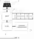
FIG. 1 shows a schematic view of the assembly of the invention, in a more general embodiment.
FIG. 2 shows a schematic view of an embodiment of the assembly of FIG. 1, where the recharge is in parallel and the discharge is in series.
LIST OF REFERENCES
-
- 1 Supercapacitors
- 2 Generation panels
- 3 Dedicated charging panels
- 4 Tracker controller
- 5 Maximum Power Point Tracking (MPPT) system
- 6 DCDC Regulators
- 7 Charge management systems
DETAILED DESCRIPTION OF A PREFERRED EXEMPLARY EMBODIMENT OF THE INVENTION
A detailed description of a preferred embodiment of the present invention is given below, with the aid of the aforementioned attached FIGS. 1-2.
The invention relates to a photovoltaic solar tracker assembly. The assembly of the invention comprises: one or more photovoltaic solar trackers; a rechargeable power supply system, including energy storage elements (1), to power the functions of the tracker (such as control and rotation); a charging system, to recharge the energy storage elements (1); and a tracker controller (4).
Each of the trackers comprises photovoltaic panels, in turn including one or more dedicated charging panels (3), which are part of the charging system, since they are intended to charge the energy storage elements (1); in addition to generation panels (2), intended for electricity generation from the photovoltaic plant.
The power system includes, as energy storage elements (1), one or more supercapacitors (1), although optionally a hybrid solution can be considered further including one or more rechargeable batteries (not shown), such as LiFePO4. Through the hybrid solution, for example, with one or two supercapacitors (1) and one or more batteries, the total cost is optimised, being able to use the supercapacitors (1) in normal operation, including absorption of current peaks, and the batteries remain in floating mode to serve as support when it is required to adopt the defence position, which increases the useful life of the batteries.
The charging system includes charging sources, such as, preferably, the dedicated charging panels (3) referred to above, although, additionally, even alternatively, it may include other charging sources, such as charging through extraction of energy from one or more strings of the generation panels, both in series and, where appropriate, in parallel. In the photovoltaic sector, “string” is understood as an assembly of photovoltaic solar panels that are connected in series to jointly provide energy.
The charging system can additionally include a maximum power point tracking system (5) (MPPT).
Also, optionally, mainly in the event that the power system does not incorporate batteries, but only supercapacitors (1), the charging system can include, additionally or alternatively, one or more DC/DC regulators (6), which adapt the voltage of the supercapacitor (1), which tends to vary significantly as it discharges, to provide the controller (4) with voltage within predetermined acceptable limits.
Preferably, the supercapacitor (1), or each one of the supercapacitors (1), is connected to the charging system and, where appropriate, some supercapacitors (1) are connected to others, so that the recharge of the supercapacitors (1) can be a recharge in series. Likewise, also preferably, the supercapacitors (1) are connected to the charging system, as well as, where appropriate, some supercapacitors (1) are connected with others, so that the recharge of the capacitors (1) is a recharge in parallel. Even more preferably, the connections allow the recharge to be selectable between a recharge in series or a recharge in parallel.
In the cases in which recharging in series is selected, i.e., with the supercapacitors (1) connected in series with one another, the MPPT system (5) acts to make the charging system work (for example, the corresponding dedicated panel or panels), at maximum power and, therefore, inject the supercapacitor (1) with maximum current, which allows a recharge of the supercapacitor (1) in a short time. More specifically, depending on the voltage of the dedicated charging panel (or panels) (3), the charging current can be in an approximate range of between 25 A if the supercapacitors (1) are fully discharged, and 3.5 A if they are fully charged.
For the cases in which a recharge in parallel is chosen, the supercapacitors (1) are connected such that they can be independently recharged; each one, or each group of them, with its charging source, such as its dedicated charging panel (3), for example. In this way, it is also possible to inject maximum current to each supercapacitor (1) in the case of using a power source other than dedicated charging panels (3).
In order for the voltage in the supercapacitors (1) not to exceed a predetermined upper limit during recharging, particularly in the case of recharging in series, one or more charge management systems can also be included in the charging system (7), which act as protection for the supercapacitors (1) that are placed in series.
In view of the foregoing, according to a preferred embodiment of the invention, the discharge of the supercapacitors (1) occurs in series and the recharge in parallel, so that the recharge in parallel has the advantage of acting as a charge management system (7). More specifically, the isolated DC/DC regulators (6) can be arranged powering each supercapacitor (1) with the required current and voltage, and with the ability to detect voltage values greater than a predetermined threshold value.
In normal operation and preferably, the tracker is powered by the dedicated charging panel or panels (3), together with the supercapacitors (1). In this way, ideally, the supercapacitors (1) hardly discharge and are always in a state of charge close to 100%.
Claims
1.-11. (canceled)
12. A photovoltaic solar tracker assembly comprising:
one or several photovoltaic solar trackers;
a rechargeable power supply system, which includes energy storage elements to power the tracker or trackers;
a charging system, to recharge the energy storage elements; and
a tracker controller;
wherein the energy storage elements comprise one or more supercapacitors.
13. The photovoltaic solar tracker assembly according to claim 12, wherein the energy storage elements consist of one or more supercapacitors.
14. The photovoltaic solar tracker assembly according to claim 12, wherein the energy storage elements comprise one or more supercapacitors and one or more rechargeable batteries,
wherein the rechargeable batteries are LiFePO4 batteries.
15. The photovoltaic solar tracker assembly according to claim 12, wherein the charging system includes a maximum power point tracking system, MPPT, to bring the charging system to operation at maximum available recharge power, injecting the energy storage elements with maximum available power.
16. The photovoltaic solar tracker assembly according to claim 12, wherein the supercapacitor or the supercapacitors are connected to the charging system and, where appropriate, some supercapacitors are connected to others, to be recharged in series.
17. The photovoltaic solar tracker assembly according to claim 12, wherein the supercapacitor or the supercapacitors are connected to the charging system and, where appropriate, some supercapacitors are connected to others, to be recharged in parallel.
18. The photovoltaic solar tracker assembly according to claim 17, wherein the recharge is carried out in parallel, the supercapacitor or the supercapacitors are connected to be independently recharged, allowing injection of maximum current to each supercapacitor.
19. The photovoltaic solar tracker assembly according to claims 17, wherein the supercapacitor or the supercapacitors can be connected to be discharged in series and charged in parallel.
20. The photovoltaic solar tracker assembly according to claim 19, which additionally includes isolated DC/DC regulators powering each supercapacitor with the required current and voltage, and with the ability to detect voltage values greater than a predetermined threshold value.
21. The photovoltaic solar tracker assembly according to claim 15, wherein the supercapacitor or the supercapacitors are connected to the charging system and, where appropriate, some supercapacitors are connected to others, to be recharged selectively in series or in parallel.
22. The photovoltaic solar tracker assembly according to claim 12, which additionally includes, for each supercapacitor or group of supercapacitors, a charge management system, so that, during recharging, each supercapacitor does not exceed a predetermined upper limit voltage value.
Images & Drawings included:


Sources:
- United States Patent and Trademark Office - verify current appl. status at the USPTO↗
Similar patent applications:
- » 20230174324
TOOL FOR SECURING AND TURNING OVER FOR ASSEMBLING PHOTOVOLTAIC SOLAR TRACKER SECTIONS, SYSTEM AND ASSOCIATED ASSEMBLY METHOD - » 20210218363
PRE-ASSEMBLY PLANT FOR PHOTOVOLTAIC SOLAR TRACKERS AND PRE-ASSEMBLY METHOD ASSOCIATED WITH SAID PLANT - » 20260128709
COUNTERBALANCE ASSEMBLIES IN PHOTOVOLTAIC SOLAR TRACKERS - » 20230030803
Locking assembly for a solar photovoltaic array tracker - » 20170294870
Pre-assembled nesting photovoltaic module bracket for solar tracker - » 20120152310
STRUCTURALLY BREAKING UP A SOLAR ARRAY OF A TWO-AXIS TRACKER ASSEMBLY IN A CONCENTRATED PHOTOVOLTAIC SYSTEM
Recent applications in this class:
- » 20260142477 2026-05-21
INFORMATION HANDLING SYSTEM RECHARGEABLE MOUSE - » 20260128601 2026-05-07
SOLAR-POWERED PORTABLE ELECTRONIC SYSTEMS WITH INTEGRATED, ARTICULATED, AND DOCK-BASED ENERGY MANAGEMENT ARCHITECTURES - » 20260128600 2026-05-07
NEONATAL POD WITH CHARGER - » 20260121421 2026-04-30
Modular Storage Unit with Electricity Generating Panel - » 20260121420 2026-04-30
SYSTEM AND METHOD OF BATTERY PACK CONFIGURATION - » 20260121419 2026-04-30
GREEN POWER-CONSUMPTION FOR EDGE DEVICES - » 20260106466 2026-04-16
SYSTEMS, APPARATUS, AND METHODS FOR UTILIZING SOLAR ENERGY AND OTHER TYPES OF RENEWABLE ENERGY - » 20260106465 2026-04-16
STANDALONE MOBILE DEVICE CHARGING AND SPEAKER DEVICE - » 20260100594 2026-04-09
POWER GENERATION SYSTEM - » 20260081434 2026-03-19
STORAGE BATTERY CONTROL DEVICE, ELECTRICITY STORAGE SYSTEM, AND STORAGE BATTERY CONTROL METHOD
Recent applications for this Assignee:
- » 20260051843 2026-02-19
SOLAR TRACKER WITH ORIENTATION CORRECTOR - » 20250202418 2025-06-19
METHOD FOR ENHANCING ENERGY PRODUCTION IN BIFACIAL SOLAR PANEL MODULES - » 20250088142 2025-03-13
SOLAR TRACKING SYSTEM WITH A MECHANICAL DRIVE MECHANISM USING A FLEXIBLE TRANSMISSION SHAFT - » 20240283401 2024-08-22
COOLING SYSTEM FOR A PHOTOVOLTAIC SOLAR PANEL - » 20240243693 2024-07-18
PHOTOVOLTAIC SOLAR TRACKER WITH OPTIMIZED WEAR AND SYNCHRONOUS TRANSMISSION - » 20240128925 2024-04-18
HIGH POWER PHOTOVOLTAIC CONNECTOR - » 20240056018 2024-02-15
SYSTEM AND METHOD FOR MAXIMIZING POWER OUTPUT IN A SOLAR PLANT AND SOLAR TRACKER THEREOF - » 20240007044 2024-01-04
BIFACIAL PHOTOVOLTAIC MODULE, SINGLE AXIS SOLAR TRACKER AND OPERATING METHOD THEREOF - » 20230421093 2023-12-28
TRACKER CONTROLLER FOR A PHOTOVOLTAIC INSTALLATION - » 20230370012 2023-11-16
Support connector, solar panel connector attachable to the support connector, and attaching system comprising said support connector and said solar panel connector