COSMETIC CONTAINER
US20260144352A1
2026-05-28
19/126,197
2023-12-12
Smart Summary: A new type of cosmetic container has been designed to make applying makeup easier. It has a cap that can rotate to cover an opening and a base that holds the cosmetic liquid. Inside, there is a connecting rod and an inner stopper that helps control the flow of the liquid. When the user shakes the container, the inner stopper moves, which compresses the storage space and allows the liquid to flow out through small openings. This design helps users control how much product they use, making it simple and effective. 🚀 TL;DR
Abstract:
The present utility model discloses a cosmetic container, comprising a cap assembly, a base assembly, a connecting rod, an inner stopper, a push block, an open head portion, and an applicator; wherein the cap assembly is configured to be rotatably connected to the base assembly to cover an opening of the base assembly, one end of the connecting rod is configured to be fixedly arranged at a bottom of the base assembly, and the other end of the connecting rod is configured to be fixedly connected to the open head portion; the applicator is configured to be fixedly arranged on and fluidly connected to the open head portion, and the inner stopper is configured to be movably arranged on the connecting rod; a circumferential side of the inner stopper is configured to be pressed against an inner wall of the base assembly, and a lower end surface of the inner stopper and the base assembly are configured to form a movable chamber; the push block is configured to be movably arranged within the movable chamber, and an upper end surface of the inner stopper, the open head portion, and the base assembly are configured to form a storage chamber for storing cosmetic liquid. During use, the user only needs to shake the base assembly of the utility model to strike the inner stopper to cause it move toward the open head portion. This, in turn, compresses the space of the storage chamber, allowing the cosmetic liquid to flow from the first through hole to the second through hole via the slit. The present utility model promotes precise control of the amount of cosmetic liquid extruded, thus facilitating ease of use and simplicity in structure.
Assignee:
- Shantou Kinhwa Plastic Industry Co., Ltd. 2 🇨🇳 Shantou, China
Applicant:
Interested in similar patents?
Get notified when new applications in this technology area are published.
Classification:
A45D34/04 » CPC main
Containers or accessories specially adapted for handling liquid toilet or cosmetic substances, e.g. perfumes Appliances specially adapted for applying liquid, e.g. using roller or ball
A45D2200/05 » CPC further
Details not otherwise provided for in Details of containers
Description
TECHNICAL FIELD
The present utility model relates to the technical field of cosmetics, particularly to a cosmetic container.
BACKGROUND
Cosmetic containers generally refer to containers used for holding cosmetic products such as creams, lotions, perfumes, and lip glosses. Examples of these cosmetic containers include cosmetic bottles and cosmetic tubes. Some of these cosmetic containers are used for strong-sealing viscous cosmetics such as creams, face creams, and lip glosses.
Cosmetics play a crucial role in the enhancement of personal appearance. Lip make-up is of particular importance in accentuating and completing the effect of facial make-up. The color and smoothness of lipstick on the lips is influenced by the condition of the lips. Therefore, lip gloss is an ideal choice for hydrating the lips. In contrast to conventional lipsticks, a relatively newer form of cosmetic, lip gloss can leave the lips moisturized and lustrous after application, and is widely embraced by modern, beauty-conscious women. Currently, lip gloss packaging bottles on the market often comprise a cylindrical bottle body, with an applicator wand attached to the bottle cap and configured to be extended into the bottle body. The applicator wand is designed to be dipped into the lip gloss material contained in the bottle body. However, as the lip gloss contained in the packaging bottle is gradually consumed, the lip gloss dipped by the applicator wand is concomitantly reduced. The above-mentioned structure of lip gloss packaging bottles and the method of use lead to a variation in the amount of lip gloss applied each time. This has the potential to have a significant impact on the user comfort and the final make-up result. In addition, since it is necessary for a user to repeatedly dip the lip gloss material with the applicator wand during use, the lip gloss material is prone to exposure to the air, which can cause the lip gloss material in the bottle to rapidly deteriorate. While there are various structural designs for lip gloss pens in the prior art, some of them are unable to contain liquid make-up dyes due to design defects. Whilst it is possible to contain them within the pens, there is still a possibility of overflow when they are being carried. This could result in defects such as inconvenience in use and reduced portability.
In view of this, there is an urgent need to improve the structure of the cosmetic containers in the prior art to facilitate operation, enhance precise control over the amount extruded during use, and prevent overflow when being carried.
SUMMARY
The technical problem addressed by the embodiments of the present utility model is to provide a cosmetic container that enables users to better control the amount of lip gloss applied with each use, thereby improving user comfort and facilitating ideal make-up results.
To address the above technical problem, the embodiments of the present utility model provide a cosmetic container, comprising a cap assembly, a base assembly, a connecting rod, an inner stopper, a push block, an open head portion, and an applicator; wherein the cap assembly is configured to be rotatably connected to the base assembly to cover an opening of the base assembly, one end of the connecting rod is configured to be fixedly arranged at a bottom of the base assembly, and the other end of the connecting rod is configured to be fixedly connected to the open head portion; the applicator is configured to be fixedly arranged on the open head portion, and the inner stopper is configured to be movably arranged on the connecting rod; a circumferential side of the inner stopper is configured to be pressed against an inner wall of the base assembly, and a lower end surface of the inner stopper and the base assembly are configured to form a movable chamber; the push block is configured to be movably arranged within the movable chamber, and an upper end surface of the inner stopper, the open head portion, and the base assembly are configured to form a storage chamber for storing cosmetic liquid, the open head portion is configured to comprise a first through-hole, and the applicator is configured to be fluidly connected to the storage chamber via the first through-hole in the open head portion; the push block is operable to strike the inner stopper to compress space of the storage chamber, and the cosmetic liquid is operable to be flown out from the applicator through the open head portion.
Preferably, a plurality of annular teeth is configured to be arranged on the connecting rod along a length direction of the connecting rod; and the inner stopper is configured to be fastened to a gap between the annular teeth.
Preferably, the base assembly is configured to comprise a tube body and a base, and the base is configured to be fitted over a bottom of the tube body.
Preferably, the applicator is configured to comprise a second through-hole, the first through-hole is configured to be fluidly connected to the second through-hole, and the connecting rod is configured to be inserted into the first through-hole.
Preferably, an opening of the tube body is configured to be fitted over a lower part of the open head portion.
Preferably, a slit is configured to be arranged on a contact portion between a circumferential wall of the first through-hole and the connecting rod.
Preferably, the cap assembly is configured to comprise a top cap and an inner cap, the top cap is configured to be fitted over the inner cap, and the top cap is configured to be rotatably connected to the tube body to cover an upper part of the tube body; the inner cap is configured to comprise an extension portion, and the extension portion is configured to be inserted into the first through-hole through the second through-hole.
Preferably, a buffer block is configured to be fixedly arranged at the bottom of the tube body.
The beneficial effects of implementing the embodiments of the present utility model are as follows:
During use, the user only needs to shake the base assembly of the utility model to make the push block move up or down, striking the inner stopper to cause it move toward the open head portion. This, in turn, compresses the space of the storage chamber, allowing the cosmetic liquid to flow from the first through hole to the second through hole via the slit. The present utility model promotes precise control of the amount of cosmetic liquid extruded, thus facilitating ease of use and simplicity in structure.
The gap between the annular teeth may be adjusted based on actual production requirements and user feedback to further ensure the controlled extrusion of the cosmetic liquid.
The present utility model makes the storage chamber into a sealed space by inserting the extension portion into the first through hole and the second through hole. Consequently, the present utility model is easy to carry, thereby ensuring that the cosmetic liquid will not overflow while being carried by the user in an outdoor setting.
BRIEF DESCRIPTION OF THE DRAWINGS
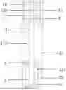
FIG. 1 is an external schematic diagram of the present utility model;
FIG. 2 is a schematic diagram of the internal overall structure of the present utility model;
FIG. 3 is a schematic diagram of the connecting rod and inner stopper of the present utility model;
FIG. 4 is a schematic diagram of the connecting rod and open head portion of the present utility model;
FIG. 5 is a schematic diagram of the open head portion of the present utility model;
FIG. 6 is a schematic diagram of the open head portion and applicator of the present utility model.
In the figures: 1. cap assembly, 11. top cap, 12. inner cap, 121. extension portion, 2. base assembly, 21. tube body, 211. movable chamber, 212. storage chamber, 22. base, 3. connecting rod, 31. annular tooth, 4. inner stopper, 5. push block, 6. open head portion, 61. first through-hole, 62. slit, 7. applicator, 72. second through-hole, 8. buffer block.
DETAILED DESCRIPTION
To make the objectives, technical solutions, and advantages of the present utility model clearer, the following provides a more detailed description of the present utility model in conjunction with the accompanying drawings.
As shown in FIGS. 1-6, a cosmetic container comprises a cap assembly 1, a base assembly 2, a connecting rod 3, an inner stopper 4, a push block 5, an open head portion 6, and an applicator 7. The cap assembly 1 is configured to be rotatably connected to the base assembly 2 to cover an opening of the base assembly 2. Specifically, the cap assembly 1 is configured to comprise a top cap 11 and an inner cap 12. The top cap 11 is configured to be fitted over the inner cap 12, and the top cap 11 is configured to be rotatably connected to a tube body 21 to cover an upper part of the tube body 21. An extension portion 121 is configured to be arranged in the inner cap 12. The base assembly 2 is configured to comprise a tube body 21 and a base 22, and the base 22 is configured to be fitted over a bottom of the tube body 21. One end of the connecting rod 3 is configured to be fixedly arranged at a bottom of the base assembly 2, and the other end of the connecting rod 3 is fixedly connected to the open head portion 6. The applicator 7 is configured to be fixedly arranged on and be fluidly connected to the open head portion 6. The open head portion 6 is configured to comprise a first through-hole 61, and the applicator 7 is configured to comprise a second through-hole 72. The first through-hole 61 is configured to be fluidly connected to the second through-hole 72, and the extension portion 121 is configured to be inserted into the first through-hole 61 via the second through-hole 72. The connecting rod 3 is configured to be inserted into the first through-hole 61, and a slit 62 is configured to be arranged on a contact portion between a circumferential wall of the first through-hole 61 and the connecting rod 3. An inner stopper 4 is configured to be movably arranged on the connecting rod 3. A plurality of annular teeth 31 are configured to be arranged on the connecting rod 3 along a length direction of the connecting rod 3, and the inner stopper 4 is configured to be fastened to a gap between the annular teeth 31. The gap of the annular teeth 31 may be adjusted according to actual production requirements and user feedback to ensure the controlled extrusion of the cosmetic liquid. A circumferential side of the inner stopper 4 is configured to be pressed against an inner wall of the base assembly 2, and a lower end surface of the inner stopper 4 and the base assembly 2 are configured to form a movable chamber 211. The push block 5 is configured to be movably arranged within the movable chamber 211. A buffer block 8 is configured to be fixedly arranged at the bottom of the tube body 21. An opening of the tube body 21 is configured to be fitted over a lower part of the open head portion 6. An upper end surface of the inner stopper 4, the open head portion 6, and the base assembly 2 are configured to form a storage chamber 212 for storing cosmetic liquid. The extension portion 121 is configured to be inserted into the first through-hole 61 and the second through-hole 72, making the storage chamber 212 into a sealed space. This makes the present utility model easy to carry and prevents the cosmetic liquid from leaking. The push block 5 is operable to strike the inner stopper 4 to compress space of the storage chamber 212, and the cosmetic liquid is operable to be flown out from the applicator 7 through the open head portion 6. During use, the user only needs to shake the base assembly 2 to make the push block 5 move up or down, striking the inner stopper 4 to cause it move toward the open head portion 6. This, in turn, compresses the space of the storage chamber 212, allowing the cosmetic liquid to flow from the first through hole 61 to the second through hole 72 via the slit 62. This promotes precise control of the amount of the cosmetic liquid extruded, thus facilitating ease of use and simplicity in structure.
Of course, the above embodiment is only intended to explain the technical concepts and features of the present utility model, and its purpose is to enable those skilled in the art to understand the content of the utility model and implement it accordingly. It should not be construed as limiting the scope of protection of the utility model. Any modifications based on the main technical spirit of the utility model should fall within the scope of protection.
Claims
1. A cosmetic container, wherein comprising:
a cap assembly (1), a base assembly (2), a connecting rod (3), an inner stopper (4), a push block (5), an open head portion (6), and an applicator (7);
wherein the cap assembly (1) is configured to be rotatably connected to the base assembly (2) to cover an opening of the base assembly (2), one end of the connecting rod (3) is configured to be fixedly arranged at a bottom of the base assembly (2), and the other end of the connecting rod (3) is configured to be fixedly connected to the open head portion (6); the applicator (7) is configured to be fixedly arranged on the open head portion (6), and the inner stopper (4) is configured to be movably arranged on the connecting rod (3); a circumferential side of the inner stopper (4) is configured to be pressed against an inner wall of the base assembly (2), and a lower end surface of the inner stopper (4) and the base assembly (2) are configured to form a movable chamber (211); the push block (5) is configured to be movably arranged within the movable chamber (211), and an upper end surface of the inner stopper (4), the open head portion (6), and the base assembly (2) are configured to form a storage chamber (212) for storing cosmetic liquid, the open head portion (6) is configured to comprise a first through-hole (61), and the applicator (7) is configured to be fluidly connected to the storage chamber (212) via the first through-hole (61) in the open head portion (6); the push block (5) is operable to strike the inner stopper (4) to compress space of the storage chamber (212), and the cosmetic liquid is operable to be flown out from the applicator (7) through the open head portion (6).
2. The cosmetic container according to claim 1, wherein a plurality of annular teeth (31) are configured to be arranged on the connecting rod (3) along a length direction of the connecting rod (3); and the inner stopper (4) is configured to be fastened to a gap between the annular teeth (31).
3. The cosmetic container according to claim 1, wherein the base assembly (2) is configured to comprise a tube body (21) and a base (22), and the base (22) is configured to be fitted over a bottom of the tube body (21).
4. The cosmetic container according to claim 3, wherein the applicator (7) is configured to comprise a second through-hole (72), the first through-hole (61) is configured to be fluidly connected to the second through-hole (72), and the connecting rod (3) is configured to be inserted into the first through-hole (61).
5. The cosmetic container according to claim 3, wherein an opening of the tube body (21) is configured to be fitted over a lower part of the open head portion (6).
6. The cosmetic container according to claim 4, wherein a slit (62) is configured to be arranged on a contact portion between a circumferential wall of the first through-hole (61) and the connecting rod (3).
7. The cosmetic container according to claim 4, wherein the cap assembly (1) is configured to comprise a top cap (11) and an inner cap (12), the top cap (11) is configured to be fitted over the inner cap (12), and the top cap (11) is configured to be rotatably connected to the tube body (21) to cover an upper part of the tube body (21); the inner cap (12) is configured to comprise an extension portion (121), and the extension portion (121) is configured to be inserted into the first through-hole (61) through the second through-hole (72).
8. The cosmetic container according to claim 1 wherein a buffer block (8) is configured to be fixedly arranged at the bottom of the tube body (21).
Images & Drawings included:


Sources:
- United States Patent and Trademark Office - verify current appl. status at the USPTO↗
Similar patent applications:
- » 20220387267
FINE BUBBLE-CONTAINING COSMETIC FOR IMPROVING DERMAL PENETRATION, MANUFACTURING SYSTEM OF FINE BUBBLE-CONTAINING COSMETIC FOR IMPROVING DERMAL PENETRATION, AND MANUFACTURING METHOD OF FINE BUBBLE-CONTAINING COSMETIC FOR IMPROVING DERMAL PENETRATION - » 20200214422
GASKET FOR COSMETIC CONTAINER AND COSMETIC CONTAINER - » 20170119129
Cosmetic container incorporating rod-shaped cosmetic container - » 17725681
Cosmetic container and pumping member for cosmetic container - » 20240172857
COSMETIC REFILL CONTAINER AND COSMETIC CONTAINER HAVING THE SAME - » 20090272400
Cosmetics Container for Containing Cosmetics - » 20060137999
Cosmetic container, cosmetic applicatior, and methods of making the same - » 20220062149
SURFACE-HYDROPHOBICIZED CELLULOSE NANOFIBERS FOR OILY THICKENER, OILY THICKENER COMPOSITION CONTAINING SAME, COSMETICS AND HYDROPHOBICIZED CELLULOSE NANOFIBER COMPLEX FOR OILY THICKENER CONTAINING SAME, OILY THICKENER COMPOSITION CONTAINING SAME, AND COSMETICS CONTAINING SAME - » 20250248908
COSMETIC COMPOSITION CONTAINING A VESICULAR CONCENTRATE CONSISTING OF A WATER SOLUTION OF LIPID VESICLES FOR COSMETIC PRODUCTS, COSMETIC PRODUCTS CONTAINING SAID COSMETIC COMPOSITION AND METHOD FOR THEIR PRODUCTION - » 20120183592
Cosmetic pigments, their production method, and cosmetics containing the cosmetic pigments
Recent applications in this class:
- » 20260144353 2026-05-28
DEVICE, SYSTEM, METHOD AND KIT FOR IMPROVED SKIN CARE PRODUCT APPLICATION - » 20260137193 2026-05-21
MULTI-MODAL THERAPEUTIC CAP ASSEMBLY FOR COSMETIC CONTAINERS - » 20260123733 2026-05-07
BEAUTY EQUIPMENT - » 20260108044 2026-04-23
COSMETIC CONTAINER TUBE WITH CHARGING ELECTRODES - » 20260083231 2026-03-26
DISPENSING HEAD FOR FLUID PRODUCT DISPENSER AND ASSOCIATED DISPENSER - » 20260013619 2026-01-15
MULTIFUNCTIONAL BOTTLE CAP WITH INTEGRATED PHYSIOTHERAPY AND SKINCARE TREATMENT ELEMENTS - » 20250386917 2025-12-25
Skin Treatment Applicator Device - » 20250380788 2025-12-18
APPARATUSES AND METHODS FOR SUNSCREEN APPLICATION - » 20250366593 2025-12-04
COSMETIC APPLICATION DEVICE - » 20250344830 2025-11-13
SUBSTANCE APPLICATOR
Recent applications for this Assignee:
- » 20180014625 2018-01-18
Cosmetic container