HARNESS SYSTEMS HAVING ADJUSTABLE SPINES
US20260144357A1
2026-05-28
18/957,273
2024-11-22
Smart Summary: A harness system features a spine that can be adjusted for different lengths. It has an inner plate with notches and a rail, along with an outer plate that includes a channel and a locking element. This locking element has a tab that fits into the notches to hold the spine in place. By changing which notch the tab engages, the length of the spine can be modified. This adjustment allows for changing the distance between the shoulder and belt parts of the harness. 🚀 TL;DR
Abstract:
According to examples, a spine for a harness system may include an inner plate having a set of locking notches arranged along a first direction and a rail extending in the first direction. The spine may also include an outer plate having a channel and a hinged locking element having a tab to selectively engage the set of locking notches. The length of the spine may be varied by varying the locking notch into which the tab of the hinged locking element is engaged. By varying the length of the spine, the distance between a shoulder member and a belt member of the harness system may be changed.
Inventors:
- Justin COOPER 6 🇺🇸 Shrewsbury, PA, United States
- Marina Rubanchenko 4 🇺🇸 Bel Air, MD, United States
- Matthew Michael Rosenthal 2 🇺🇸 Parkville, MD, United States
- Daniel MCGUINNESS 1 🇺🇸 Parkton, MD, United States
- YiCai WEI 1 🇨🇳 Suzhou, China
- Randall J. PUZZITIELLO 1 🇺🇸 Idlewylde, MD, United States
- Samantha LAWSON 1 🇺🇸 Frederick, MD, United States
Assignee:
- Black & Decker, Inc. 949 🇺🇸 New Britain, CT, United States
Applicant:
Interested in similar patents?
Get notified when new applications in this technology area are published.
Classification:
A45F3/14 » CPC main
Travelling or camp articles ; Sacks or packs carried on the body Carrying-straps; Pack-carrying harnesses
A45F2003/001 » CPC further
Travelling or camp articles ; Sacks or packs carried on the body Accessories
A45F3/00 IPC
Travelling or camp articles ; Sacks or packs carried on the body
Description
FIELD
The present disclosure is directed to harness systems for power equipment. Particularly, the present disclosure is directed to an adjustable spine for a harness system that is extendable to multiple positions to vary a distance between a belt member and a shoulder member of the harness system.
BACKGROUND
Power equipment, such as garden machines, include a motor or an engine powered by electricity or fossil fuels. The power equipment include brush cutters, blowers, string trimmers, edgers, and the like. As battery and engine sizes have increased, so too has the weight of many of these power equipment. The increased weight also resulted in increased arm stress and fatigue on a user of the power equipment. Harness systems that are to sit on a user's shoulders that help to distribute the weight of the power equipment have been employed to alleviate some of the arm stress and fatigue on the user.
SUMMARY
This section provides a general summary of the disclosure, and is not a comprehensive disclosure of its full scope or all of its features.
According to embodiments disclosed herein, a spine for a harness system may include an inner plate having a set of locking notches arranged along a first direction and a rail extending in the first direction. The spine may also include an outer plate having a channel, in which the rail of the inner plate is to rest within the channel and enable sliding movement between the inner plate and the outer plate. The outer plate may also have a hinged locking element having a tab to selectively engage the set of locking notches. The length of the spine may be varied by varying the locking notch into which the tab of the hinged locking element is engaged.
According to embodiments disclosed herein, a harness system may include a shoulder member, a belt member; and a spine. The spine may include an inner plate connected to the shoulder member, in which the inner plate may include a plurality of locking notches arranged in a direction from the belt member to the shoulder member. The spine may also include an outer plate connected to the belt member, in which the outer plate may include a pair of hinged locking elements having tabs to selective engage the locking notches. The inner plate may be in sliding engagement with the outer plate and the inner plate is lockable into a plurality of positions with respect to the outer plate based on the locking notches to which the tabs of the pair of hinged locking elements are engaged.
According to embodiments disclosed herein, a clamping system for a bull handle of a power equipment may include an upper clamp member, a rotational position locking member, and a lower clamp member. The rotation position locking member may have a plurality of first mating elements, in which some of the plurality of first mating elements are arc segments and some of the plurality of first mating elements are line segments that extend from a center of the rotational position locking member to edges of the rotational position locking member. The lower clamp member may be positioned between the upper clamp member and the rotational position locking member. In addition, the lower clamp member may include a plurality of second mating elements that are to mate with the plurality of first mating elements, in which some of the plurality of second mating elements are arc segments and some of the plurality of second mating elements are line segments that extend from a center of the lower clamp member to edges of the lower clamp member. The bull handle is to be held between the upper clamp member and the lower clamp member and the plurality of first mating elements and the plurality of second mating elements are arranged to enable the bull handle to be securely held in either a storage position or usage position while preventing the bull handle from being securely held when in a position between the storage position and the usage position.
BRIEF DESCRIPTION OF THE DRAWINGS
Features of the present disclosure are illustrated by way of example and not limited in the following figure(s), in which like numerals indicate like elements, in which:
FIG. 1A shows a rear view of a harness system to be worn on a user's back, in accordance with an embodiment of the present disclosure;
FIG. 1B shows a rear view of the harness system shown in FIG. 1A worn on a user's back, in accordance with an embodiment of the present disclosure;
FIG. 1C shows a front view of the harness system shown in FIGS. 1A and 1B worn on a user's back with a power equipment supported on the harness system, in accordance with an embodiment of the present disclosure;
FIG. 1D shows a side view of a hip pad of the harness system shown in FIGS. 1A-1C on which a power equipment is supported, in accordance with an embodiment of the present disclosure;
FIGS. 2A and 2B, respectively, show front perspective views of the spine shown in FIG. 1A, in accordance with an embodiment of the present disclosure;
FIG. 2C shows a top view of the spine shown in FIG. 1A, according to an embodiment of the present disclosure;
FIG. 3A shows a rear view of the inner plate shown in FIGS. 2A and 2B, in accordance with an embodiment of the present disclosure;
FIGS. 3B and 3C, respectively, show a rear view of a section of the spine shown in FIGS. 2A and 2B, in which a first hinged locking element and a second hinged locking element are in various positions, in accordance with an embodiment of the present disclosure;
FIG. 4A shows a diagram of an inner plate connection system for connecting the spine shown in FIGS. 2A-2B to a shoulder member, in accordance with an embodiment of the present disclosure;
FIG. 4B shows a diagram of an outer plate connection system for connecting the spine shown in FIGS. 2A-2B to a belt member, in accordance with an embodiment of the present disclosure;
FIG. 5A shows a diagram of the harness system shown in FIG. 1A and a power equipment supported on the harness system, in accordance with an embodiment of the present disclosure;
FIG. 5B shows a diagram of the power equipment shown in FIG. 5A, in which a bull handle of the power equipment is in a storage position, in accordance with an embodiment of the present disclosure;
FIG. 6A shows an exploded view of the clamping system shown in FIGS. 5A and 5B, in accordance with an embodiment of the present disclosure;
FIG. 6B shows a bottom perspective view of the lower clamp member shown in FIG. 6A, in accordance with an embodiment of the present disclosure;
FIG. 6C shows a top perspective view of the rotational position locking member shown in FIG. 6A, in accordance with an embodiment of the present disclosure; and
FIG. 6D shows a side view of the lower clamp member and the rotational position locking member in an unlocked position, i.e., prior to or after the bull handle is in one of the usage position or the storage position, in accordance with an embodiment of the present disclosure.
DETAILED DESCRIPTION
Harness systems for supporting power equipment have gained in popularity because the harness systems make it relatively easier for operators of the power equipment to carry and use the power equipment. Particularly, for instance, the harness systems may support some or all of the weight of the power equipment during use of the power equipment. By supporting most or all of the weight of the power equipment on an operator's shoulders through use of the harness systems, stress and fatigue on the operator's arms may be reduced.
Disclosed herein are harness systems that include a shoulder member, a belt member, and a spine having an adjustable length. The spine may include an inner plate that is removably mounted to the shoulder member and an outer plate that is removably mounted to the belt member. The inner plate may be in slidable engagement with the outer plate to adjust the distance between the belt member and the shoulder member. The relative positions of the inner plate and the outer plate may be locked through selective engagement of at least one tab on the outer plate and locking notches on the inner plate. Particularly, the at least one tab may be connected to a living hinge that biases the position of the tab toward the notches.
Through implementation of the harness systems and the spine disclosed herein, the distance between the shoulder member and the belt member may easily be varied. In one regard, varying the distance may enable operators having different heights and/or different length torsos to adjust the harness systems to better fit their bodies. The operators may thus adjust the harness systems to improve ergonomics in using the harness systems.
Also disclosed herein are clamping systems for a bull handle of a power equipment that enable the bull handle to securely be held in a storage position or a usage position. While in the usage position, an operator of the power equipment may readily grasp the bull handle to maneuver its position during use of the power equipment. While in the storage position, the bull handle may be rotated from the usage position. As a result, the width of the power equipment may be reduced, which may make storage or transport of the power equipment simpler.
The clamping systems disclosed herein may include an upper clamp member, a rotational position locking member, and a lower clamp member. The rotational position locking member has a plurality of first mating elements, in which some of the plurality of first mating elements are arc segments and some of the plurality of first mating elements are line segments that extend from a center of the rotational position locking member to edges of the rotational position locking member. The lower clamp member may be positioned between the upper clamp member and the rotational position locking member.
In addition, the lower clamp member may include a plurality of second mating elements that are to mate with the plurality of first mating elements. Some of the plurality of second mating elements are arc segments and some of the plurality of second mating elements are line segments that extend from a center of the lower clamp member to edges of the lower clamp member. In addition, a bull handle is to be held between the upper clamp member and the lower clamp member. The plurality of first mating elements and the plurality of second mating elements are arranged to enable the bull handle to be securely held in either a storage position or usage position while preventing the bull handle from being securely held when in a position between the storage position and the usage position.
Through implementation of the clamping systems disclosed herein, the bull handle may not be securely held in a position with respect to a pole of the power equipment when the bull handle is positioned between the usage position and the storage position. Particularly, the plurality of first mating elements may not securely mate with the plurality of second mating elements unless the bull handle is in one of the storage position and the usage position. As a result, an operator of the power equipment immediately recognizes that the bull handle is not in one of the storage position or the usage position, and can take necessary steps accordingly.
Before continuing, it is noted that as used herein, the terms “includes” and “including” mean, but are not limited to, “includes” or “including” and “includes at least” or “including at least.” The term “based on” means, but is not limited to, “based on” and “based at least in part on.”
FIG. 1A shows a rear view of a harness system 100 to be worn on a user's back, in accordance with an embodiment of the present disclosure. FIG. 1B shows a rear view of the harness system 100 shown in FIG. 1A worn on a user's back, in accordance with an embodiment of the present disclosure. FIG. 1C shows a front view of the harness system 100 shown in FIGS. 1A and 1B worn on a user's back with a power equipment 104 supported on the harness system 100, in accordance with an embodiment of the present disclosure. FIG. 1D shows a side view of a hip pad 102 of the harness system 100 shown in FIGS. 1A-1C on which a power equipment 104 is supported, in accordance with an embodiment of the present disclosure. It should be understood that the harness system 100 depicted in FIGS. 1A-1D may include additional components and that some of the components described herein may be removed and/or modified without departing from the scope of the harness system 100 disclosed herein.
As shown in FIGS. 1A-1D, the harness system 100 may include a hip pad 102 onto which a power equipment 104 (shown in FIGS. 1B-1D) may be supported or attached. The harness system 100 may also include a shoulder member 110 onto which the hip pad 102 is connected. Particularly, the shoulder member 110 may include a first side adjustment strap 112a, a second side adjustment strap 112b, a third side adjustment strap 112c, a pair of shoulder pads 114, and a side strap 115. A first end of the first side adjustment strap 112a may be connected to one of the shoulder pads 114 and a second end of the first side adjustment strap 112a may be releasably attached to the spine 130. In addition, the hip pad 102 may include an opening through which the first side adjustment strap 112a may be inserted to support the hip pad 102. The second side adjustment strap 112b may be connected to the other one of the shoulder pads 114 (e.g., via a clip 116) and the side strap 115. The third side adjustment strap 112c may be connected to the side strap 115 and the spine 130. The side strap 115 may hug a user's rib cage while in use and may help give lateral support as the weight of the power equipment 104 pulls on the hip pad 102.
As shown in FIGS. 1A and 1C, a user may secure the shoulder member 110 of the harness system 100 on the user's body by clipping together a pair of mating clips 116. In some examples, the lengths of the first, second, and third side adjustment straps 112a-112c may be adjustable such that a user may adjust the fit of the shoulder member 110 on the user's body. Additionally, the position of the side strap 115 may adjusted to fit comfortably on the user's body.
The harness system 100 may also include a belt member 120 that a user may position around the user's waist or hip during use as shown in FIGS. 1B and 1C. The belt member 120 may better hold the harness system 100 on the user's body by clipping together a pair of mating clips 106. In addition, the belt member 120 may be adjustable such that the user may adjust the fit of the belt member 120 on the user's hip or waist. At least a portion of the belt member 120 may be padded to increase the user's comfort.
As shown in FIGS. 1A and 1B, the spine 130 may include a number of open loops 132 along both sides of the spine 130 into which the first side adjustment strap 112a and the third side adjustment strap 112c may be inserted and strapped. The side adjustment straps 112a and 112c may be strapped to respective ones of the open loops 132 to enable the adjustments of locations of the hip pad 102 and the side strap 115 on a user's body.
As discussed herein, the length of the spine 130 is adjustable to enable the distance between the belt member 120 and the shoulder member 110 to be adjustable. By adjusting the distance between the shoulder member 110 and the belt member 120 by adjusting the length of the spine 130, the harness system 100 may be adjusted to comfortably fit users who have different heights and/or different length torsos.
According to examples, the power equipment 104 is a brush cutter, trimmer, edger, or the like, having a bull handle, as shown in FIG. 1C. In addition, the harness system 100 supports at least part of the weight of the power equipment 104. Particularly, the hip pad 102 may include a clip 108 that is mounted to the hip pad 102, in which the clip 108 may be inserted into an opening 105 of the power equipment 104. In use, some or all of the weight of the power equipment 104 may be supported on the user's shoulders through the harness system 100.
FIGS. 2A and 2B, respectively, show front perspective views of the spine 130 shown in FIG. 1A, in accordance with an embodiment of the present disclosure. FIG. 2C shows a top view of the spine 130 shown in FIG. 1A, according to an embodiment of the present disclosure. FIG. 2A shows the spine 130 in a collapsed position and FIG. 2B shows the spine 130 in an extended position. As shown in FIGS. 2A-2C, the spine 130 includes an inner plate 200 and an outer plate 202, in which the inner plate 200 is in sliding arrangement with the outer plate 202. As the inner plate 200 may be attached to the shoulder member 110 and the outer plate 202 may be attached to the belt member 120, the distance between the belt member 120 and the shoulder member 110 may be varied by varying the position of the inner plate 200 with respect to the outer plate 202 as discussed herein.
As shown in FIG. 2C, the inner plate 200 may include a pair of rails 210 that extend along the longitudinal direction of the inner plate 200. In other words, the pair of rails 210 extend in the same direction as the direction in which the inner plate 200 is movable with respect to the outer plate 202. In addition, the outer plate 202 may include a pair of channels 220 in which the channels 220 extend in the same direction as the rails 210. As shown, the pair of rails 210 of the inner plate 200 rest within the channels 220 and enable sliding movement between the inner plate 200 and the outer plate 202. That is, the channels 220 may limit lateral movement of the inner plate 200 with respect to the outer plate 202 as the inner plate 200 slides with respect to the outer plate 202 along the channels 220.
With reference to FIGS. 2A-2C, the outer plate 202 may also include a first hinged locking element 230 and a second hinged locking element 232 positioned within an opening 234 of the outer plate 202. The first hinged locking element 230 may include a first living hinge 236 that is resiliently connected to a body 238 of the outer plate 202. The first hinged locking element 230 may also include a first lever element 240 at a free end of the first living hinge 236, and a first tab 242 extending outwardly from the first lever element 240 (see FIGS. 2C and 3B).
The second hinged locking element 232 may include a second living hinge 244 that is resiliently connected to the body 238. The second hinged locking element 232 may also include a second lever element 246 positioned at a free end of the second living hinge 244, and a second tab 248 extending outwardly from the second lever element 246.
FIG. 3A shows a rear view of the inner plate 200, in accordance with an embodiment of the present disclosure. FIGS. 3B and 3C, respectively, show a rear view of a section of the spine 130 in which the first hinged locking element 230 and the second hinged locking element 232 are in various positions, in accordance with an embodiment of the present disclosure. As shown in FIGS. 3A-3C, the inner plate 200 may include a first set of locking notches 300 arranged along a first direction, e.g., the direction in which the rails 210 and the channels 220 extend. The inner plate 200 may also include a second set of locking notches 302 arranged along the first direction. In addition, the inner plate 200 may include a slot 304 positioned between the first set of locking notches 300 and the second set of locking notches 302. As shown, for instance, in FIG. 3B, the hinged locking elements 230, 232 may be positioned within the slot 304 when the inner plate 200 is slidably engaged with the outer plate 202.
As shown in FIG. 3B, the first tab 242 may be engaged with, e.g., seated within, one of the locking notches in the first set of locking notches 300. Likewise, the second tab 248 may be engaged with, e.g., seated within, one of the locking notches in the second set of locking notches 302. In this regard, the first tab 242 and the second tab 248 may have complementary sizes and shapes as the locking notches 300, 302.
According to examples, the first living hinge 236 and the second living hinge 244 may be biased toward the outer edges of the body 238 such that the first tab 242 and the second tab 248 may be held within respective notches 300, 302 of the inner plate 200. That is, the first tab 242 may remain seated within one of the notches 300 and the second tab 248 may remain seated within another one of the notches 302 when external pressure is not applied to the first hinged locking element 230 and the second hinged locking element 232.
However, when sufficient pressure is applied to move the first lever element 240 and the second lever element 246 toward each other at least a certain distance, for instance, as shown in FIG. 3C, the first and second tabs 242, 248 may be moved away from their respective locking notches 300, 302 such that they may clear the edges of the locking notches 300. When the first and second tabs 242, 248 are in the positions shown in FIG. 3C, the inner plate 200 may be movable with respect to the outer plate 202. In addition, the inner plate 200 may be locked into another position with respect to the outer plate 202 by releasing the pressure being applied to the first lever element 240 and the second lever element 246. That is, release of the pressure may cause the first and second living hinges 236, 244 to move the first and second tabs 242, 248 into respective notches 300, 302 on the inner plate 200 depending upon the position of the inner plate 200 with respect to the outer plate 202. In this manner, the length of the spine 130 may be adjusted.
According to examples, the inner plate 200 and the outer plate 202 may be formed of a substantially rigid material, such as a hard plastic, a composite material, a metal, and/or the like. When in the collapsed position (FIG. 2A), the spine 130 may have a length of between around 12-16 inches in a collapsed position. In addition, when in the extended position (FG. 2B), the spine 130 may have a length of between around 18-24 inches.
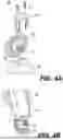
FIG. 4A shows a diagram of an inner plate connection system 400 for connecting the spine 130 to the shoulder member 110, in accordance with an embodiment of the present disclosure. FIG. 4B shows a diagram of an outer plate connection system 420 for connecting the spine 130 to the belt member 120, in accordance with an embodiment of the present disclosure. It should be understood that the inner plate and the outer plate connection systems 400, 420 shown in FIGS. 4A and 4B are shown for purposes of illustration and that the spine 130 may be connected to the shoulder member 110 and the belt member 120 using other types of connection systems without departing from a scope of the present disclosure.
FIG. 4A shows a top portion of the inner plate 200 and FIG. 4B shows a bottom portion of the outer plate 202. As shown in FIG. 4A, the inner plate 200 includes an upper slot 402 into which a pin 404 of a connecting member 406 may be inserted. The connecting member 406 may be mounted to the shoulder member 110 through any suitable fastening device. For instance, the connecting member 406 may be sewn, riveted, or the like, onto the shoulder member 110. In addition, a top cover piece 408 may be inserted into the top of the inner plate 200, in which the top cover piece 408 may hold down the pin 404 of the connecting member 406. The top cover piece 408 may also be fastened in place through use of multiple screws 410.
As shown in FIG. 4B, the outer plate 202 includes a lower slot 422 into which a pin 424 of a connecting member 426 may be inserted. The connecting member 426 may be mounted to the belt member 120 through any suitable fastening device. For instance, the connecting member 426 may be sewn, riveted, or the like, onto the belt member 120. In addition, a bottom cover piece (not shown), which may be similar to the top cover piece 408, may be inserted into the bottom of the outer plate 202, in which the bottom cover piece may hold down the pin 424 of the connecting member 426. The bottom cover piece may also be fastened in place through use of multiple screws (not shown), in a similar manner to the top cover piece 408.
In some examples, the top cover piece 408 may hold the pin 404 in a manner that enables the pin 404 to be rotated with respect to the spine 130. Likewise, the bottom cover piece may hold the pin 424 in a manner that enables the pin 424 to be rotated with respect to the spine 130. In this regard, the shoulder member 110 and the belt member 120 may be rotated, at least partially, with respect to the spine 130. The ability to rotate the shoulder member 110 and the belt member 120 with respect to the spine 130 may enhance comfort of the harness system 100 to a user.
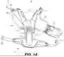
As discussed herein, and as shown in FIG. 5A, the hip pad 102 of the harness system 100 may support a power equipment 500. In the example shown in FIG. 5A, the power equipment 500 may be a brush cutter, although in other examples, the power equipment 500 may be another type of equipment. The power equipment 500 is depicted as including a bull handle 502 mounted to a pole 504 of the power equipment 500. The bull handle 502 may be mounted to the pole 504 through use of a clamping system 506 that enables the bull handle 502 to be rotated between a usage position as shown in FIG. 5A and a storage position as shown in FIG. 5B.
In the usage position shown in FIG. 5A, the bull handle 502 may be substantially perpendicular to the pole 504, while in the storage position as shown in FIG. 5B, the bull handle 502 may be substantially parallel to the pole 504. In this regard, the power equipment 500 may occupy a substantially smaller amount of space while in the storage position than while in the usage position.
As shown in FIGS. 5A and 5B, the bull handle 502 may include a pair of handles 508 and a trigger 510. While in the usage position, a user may readily grasp the handles 508 to maneuver the power equipment 500. However, while in the storage position, it may be relatively difficult or uncomfortable for a user to grasp the handles 508 and maneuver the power equipment 500 for use. In some examples, while in the storage position, the trigger 510 may be disabled, e.g., depression of the trigger 510 may not cause a motor (not shown) of the power equipment 500 to be enabled. As a result, the power equipment 500 may not be operable when the bull handle 502 is in the storage position.
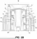
FIG. 6A shows an exploded view of the clamping system 506 shown in FIGS. 5A and 5B, in accordance with an embodiment of the present disclosure. As shown in FIG. 6A, the clamping system 506 may include an upper clamp member 600 and a lower clamp member 602. The upper clamp member 600 and the lower clamp member 602 may include respective U-shaped sections 604, 606 into which a portion of the bull handle 502 may be supported. The clamping system 506 may also include a bolt 608, a spring 610, rotational position locking member 612, and a nut 614. The clamping system 506 may further include a pole clamp member 616, in which the pole clamp member 616 and the rotational position locking member 612 may support the pole 504 through use of fasteners 618.
In use, the bolt 608 may be rotated in a first direction, e.g., clockwise, to tighten the upper clamp member 600 onto the lower clamp member 602 and the rotational position locking member 612 onto the lower clamp member 602. Likewise, the bolt 608 may be rotated in a second direction, e.g., counter-clockwise, to loosen the upper clamp member 600 from the lower clamp member 602 and the rotational position locking member 612 from the lower clamp member 602.
While the clamping system 506 is in the tightened position, the bull handle 502 may be held in position and may be prevented from rotating about a lateral axis of the bull handle 502, for instance, through friction. In addition, the bull handle 502 may be held in one of the usage position and the storage position. While the clamping system 506 is in the loosened position, the bull handle 502 may be free to rotate within the U-shaped sections 604, 606. Particularly, the bull handle 502 may rotate about the y-axis as shown in FIG. 6A. In addition, the bull handle 502 may be rotated into or out of one of the usage position and the storage position, e.g., about the z-axis as shown in FIG. 6A. The spring 610 may help disengage the rotational position locking member 612 from the lower clamp member 602 as the bolt 608 is turned counter-clockwise.
According to examples, the clamping system 506 may prevent the bull handle 502 from being securely held in a position between the usage position and the storage position. That is, the rotational position locking member 612 and the lower clamp member 602 may include mating elements that may prevent proper seating when the bull handle 502 is in a position between the usage position and the storage position. As shown in FIGS. 6B and 6C, the features may enable proper seating between the rotational position locking member 612 and the lower clamp member 602 when the bull handle 502 is in either of the usage position or the storage position.
FIG. 6B shows a bottom perspective view of the lower clamp member 602 shown in FIG. 6A, in accordance with an embodiment of the present disclosure. FIG. 6C shows a top perspective view of the rotational position locking member 612 shown in FIG. 6A, in accordance with an embodiment of the present disclosure. FIG. 6D shows a side view of the lower clamp member 602 and the rotational position locking member 612 in an unlocked position, i.e., prior to or after the bull handle 502 is in one of the usage position or the storage position, in accordance with an embodiment of the present disclosure.
As shown in FIG. 6B, the lower clamp member 602 may include a first set of channels 630 that are arranged as arc segments and a second set of channels 632 arranged as line segments that extend in directions from a center of the lower clamp member 602 to edges of the lower clamp member 602. According to examples, the second set of channels 632 may be deeper than the first set of channels 630. The lower clamp member 602 may also include an inner ring opening 634. The inner ring opening 534 may be significantly deeper than the first set of channels 630.
As shown in FIG. 6C, the rotational position locking member 612 may include a first set of protrusions 640 that are arranged as arc segments and a second set of protrusions 642 arranged as line segments that extend in directions from a center of the rotational position locking member 612 toward edges of the rotational position locking member 612. According to examples, the second set of protrusions 642 may be taller than the first set of protrusions 640. By being taller than the first set of protrusions 640, the second set of protrusions 642 may act as a guide as the bolt 608 tightens the lower clamp member 602 and the rotational position locking member 612 together when the bull handle 502 is in one of the usage position and the storage position.
In addition, the rotational position locking member 612 may include an inner ring column 644, in which the inner ring column 644 may be significantly taller than the second set of protrusions 642. According to examples, the inner ring column 644 may be inserted into the inner ring opening 634, which may enable the lower clamp member 602 to rotate smoothly with respect to the rotational position locking member 612 when the clamping system 506 is in a loosened position. In addition, the first set of protrusions 640 and the second set of protrusions 642 may function in concert with the first set of channels 630 and the second set of channels 632 to provide discreet intervals at which the bull handle 502 may be securely positioned with respect to the pole 504.
When the bull handle 502 is in the usage position (as shown in FIG. 5A) or in the storage position (as shown in FIG. 6B), the first set of protrusions 640 may be seated within the first set of channels 630. In addition, the second set of protrusions 642 may be seated within the second set of channels 632. However, when the bull handle 502 is between the usage position and the storage position, the first set of protrusions 640 may not be properly seated within the first set of channels 630 and the second set of protrusions 642 may not be properly seated within the second set of channels 632. As a result, tightening of the bolt 608 may not result in a secure mating between the lower clamp member 602 and the rotational position locking member 612. In other words, when the bull handle 502 is not in the usage position or the storage position, the clamping system 506 may not be tightened completely and the bull handle 502 may be securely connected to the pole 504.
Although the lower clamp member 602 has been described herein as having channels 630, 632, and an inner ring opening 634 and the rotational position locking member 612 has been described herein as having protrusions 640, 642, and an inner ring column 644, it should be understood that the lower clamp member 602 may instead have the protrusions and the rotational position locking member 612 may instead have channels in some examples. In other examples, the lower clamp member 602 may have a set of first mating elements and the rotational position locking member 612 may have a set of second mating elements, in which the first mating elements and the second mating elements may include combinations of the channels and the protrusions. In these examples, the lower clamp member 602 and the rotational position locking member 612 may each have some channels and some protrusions. In addition, the channels and the protrusions in the lower clamp member 602 may mate with the channels and the protrusions in the rotational position locking member 612 when the bull handle 502 is in the usage position or the storage position.
Although described specifically throughout the entirety of the instant disclosure, representative examples of the present disclosure have utility over a wide range of applications, and the above discussion is not intended and should not be construed to be limiting, but is offered as an illustrative discussion of aspects of the disclosure.
What has been described and illustrated herein is an example of the disclosure along with some of its variations. The terms, descriptions and figures used herein are set forth by way of illustration only and are not meant as limitations. Many variations are possible within the spirit and scope of the disclosure, which is intended to be defined by the following claims—and their equivalents—in which all terms are meant in their broadest reasonable sense unless otherwise indicated.
Claims
What is claimed is:1. A spine for a harness system, the spine comprising:
an inner plate comprising:
a set of locking notches arranged along a first direction; and
a rail extending in the first direction;
an outer plate comprising:
a channel, wherein the rail of the inner plate is to rest within the channel and enable sliding movement between the inner plate and the outer plate; and
a hinged locking element having a tab to selectively engage the set of locking notches, wherein a length of the spine is varied by varying the locking notch of the set of locking notches into which the tab of the hinged locking element is engaged.
2. The spine of claim 1, wherein:
the inner plate further comprises:
a second set of locking notches arranged along the first direction; and
a second rail extending in the first direction;
the outer plate further comprises:
a second channel, wherein the second rail of the inner plate is to slidably engage the second channel; and
a second hinged locking element having a second tab to selectively engage the second set of locking notches.
3. The spine of claim 2, wherein the inner plate further comprises a slot positioned between the set of locking notches and the second set of locking notches, and wherein the hinged locking element and the second hinged locking element are to be positioned within the slot when the inner plate is slidably engaged with the outer plate.
4. The spine of claim 1, wherein the inner plate further comprises an inner plate connection mechanism to removably connect the inner plate with a shoulder member of the harness system, and wherein the inner plate connection mechanism comprises a top cover piece that is to be fastened to the inner plate and securely hold a connecting member that is to be mounted to a shoulder member of the harness system.
5. The spine of claim 4, wherein the connecting member comprises a pin, and wherein the inner plate is to be rotatably mounted on the pin to enable the spine to be rotatable relative to the shoulder member.
6. The spine of claim 2, wherein the outer plate comprises a body having an opening into which the hinged locking element and the second hinged locking element extend, and wherein the hinged locking element and the second hinged locking element are resiliently mounted to the body and are biased toward opposite sides of the body.
7. The spine of claim 6, wherein the hinged locking element further comprises:
a first living hinge connecting the tab of the hinged locking element to the body, wherein the tab extends away from the first living hinge toward a first edge of the body; and
wherein the second hinged locking element further comprises:
a second living hinge connecting the second tab of the second hinged locking element to the body; and
wherein the second tab extends away from the second living hinge toward a second edge of the body.
8. The spine of claim 1, wherein the outer plate further comprises an outer plate connection mechanism to removably and rotatably connect the outer plate with a belt member of the harness system.
9. A harness system comprising:
a shoulder member;
a belt member; and
a spine comprising:
an inner plate connected to the shoulder member, the inner plate comprising:
a plurality of locking notches arranged in a direction from the belt member to the shoulder member; and
an outer plate connected to the belt member, the outer plate comprising:
a pair of hinged locking elements having tabs to selective engage the locking notches, wherein the inner plate is in sliding engagement with the outer plate and the inner plate is lockable into a plurality of positions with respect to the outer plate based on the locking notches to which the tabs of the pair of hinged locking elements are engaged.
10. The harness system of claim 9, wherein the inner plate comprises a pair of rails and the outer plate comprises a pair of channels, and wherein the pair of rails of the inner plate are to sit within the pair of channels and enable sliding movement between the inner plate and the outer plate.
11. The harness system of claim 9, wherein the inner plate further comprises a slot positioned between a first set of the plurality of locking notches and a second set of the plurality of locking notches, and wherein the pair of hinged locking elements are positioned within the slot.
12. The harness system of claim 9, wherein the inner plate comprises an inner plate connection mechanism to removably and rotatably connect the inner plate with the shoulder member and the outer plate comprises an outer plate connection mechanism to removably and rotatably connect the outer plate with the belt member.
13. The harness system of claim 9, wherein the outer plate comprises a body having an opening into which the pair of hinged locking elements extend.
14. The harness system of claim 13, wherein each of the pair of hinged locking elements comprises a first living hinge that connects a first tab of a first hinged locking element to the body and a second living hinge that connects a second tab of a second hinged locking element to the body.
15. The harness system of claim 14, wherein the first hinged locking element comprises a first lever element at a free end of the first living hinge and the second hinged locking element comprises a second lever element at a free end of the second living hinge.
16. A clamping system for a bull handle of a power equipment, the clamping system comprising:
an upper clamp member;
a rotational position locking member having a plurality of first mating elements, wherein some of the plurality of first mating elements are arc segments and some of the plurality of first mating elements are line segments that extend from a center of the rotational position locking member to edges of the rotational position locking member; and
a lower clamp member positioned between the upper clamp member and the rotational position locking member, the lower clamp member comprising:
a plurality of second mating elements that are to mate with the plurality of first mating elements, wherein some of the plurality of second mating elements are arc segments and some of the plurality of second mating elements are line segments that extend from a center of the lower clamp member to edges of the lower clamp member; and
wherein the bull handle is to be held between the upper clamp member and the lower clamp member and wherein the plurality of first mating elements and the plurality of second mating elements are arranged to enable the bull handle to be securely held in either a storage position or usage position while preventing the bull handle from being securely held when in a position between the storage position and the usage position.
17. The clamping system of claim 16, wherein the line segments of the first mating elements and the line segments of the second mating elements have higher heights or deeper depths than the arc segments of the first mating elements the arc segments of the second mating elements.
18. The clamping system of claim 16, wherein the line segments and the arc segments of the first mating elements have heights and wherein the heights of the line segments are higher than the heights of the arc segments of the first mating elements.
19. The clamping system of claim 16, wherein the line segments and the arc segments of the second mating elements have depths and wherein the depths of the line segments of the second mating elements are deeper than the depths of the line segments of the second mating elements.
20. The clamping system of claim 16, wherein the rotational position locking member comprises an inner ring column and the lower clamp member comprises an inner ring opening, and wherein the inner ring column is inserted within the inner ring opening to enable smooth rotation between the lower clamp member and the rotational position locking member when the bull handle is between the storage position and the usage position.
Images & Drawings included:


Sources:
- United States Patent and Trademark Office - verify current appl. status at the USPTO↗
Recent applications in this class:
- » 20260137200 2026-05-21
TACTICAL TORSO TOOL CARRIER AND NETWORKED CONTROL AND COMMUNICATION SYSTEM - » 20260137199 2026-05-21
Hands Free Shoe Carrier - » 20260090626 2026-04-02
TOOL CARRYING HARNESS AND STRAP ASSEMBLY FOR ADJUSTING THE SAME - » 20260083236 2026-03-26
BACKPACK INCLUDING SUSPENSION STRAP - » 20260069023 2026-03-12
MULTIFUNCTIONAL CARRYING STRAP SYSTEM - » 20260033617 2026-02-05
APPARATUS FOR STABILIZING THE CORE OF A PERSON - » 20250380790 2025-12-18
ATTACHMENT DEVICE TO AN ANCHOR POINT AND METHOD FOR RELEASING ONE SUCH DEVICE - » 20250375021 2025-12-11
Adjustable Harness Device for Carrying Personal Items - » 20250338949 2025-11-06
ATTACHMENT PANEL AND RECEIVER SYSTEM FOR TACTICAL VESTS - » 20250325092 2025-10-23
CARRIER
Recent applications for this Assignee:
- » 20260145311 2026-05-28
High Inertia Driver System - » 20260145208 2026-05-28
PRESSURE WASHER WITH A MOVABLE CROSSBAR - » 20260138300 2026-05-21
CHAIN SAW - » 20260097412 2026-04-09
PRESSURE WASHER WITH ROLL CAGE - » 20260055669 2026-02-26
HAND-HELD POWER TOOL - » 20260051788 2026-02-19
Powered Fastening Tool Including Driver Directly Coupled To Electric Motor - » 20260027673 2026-01-29
SHIELD ASSEMBLY FOR POWER TOOL - » 20260025090 2026-01-22
MOTOR DRIVE CONTROL SCHEME FOR REDUCING NEGATIVE CURRENTS - » 20260019018 2026-01-15
VARIABLE CURRENT CLIP CONTROL IN POWER TOOL - » 20250357873 2025-11-20
STALL DETECTION IN FIELD-ORIENTED SENSORLESS MOTOR CONTROL