FOLDABLE TABLE
US20260144360A1
2026-05-28
19/200,231
2025-05-06
Smart Summary: A foldable table has a bracket that holds the table surface. It features a base that can rotate around a fixed point, allowing the table to fold up. There is a locking system in the base that keeps the table at a certain angle when it is set up. An adjustment mechanism lets users change the angle of the table surface if needed. This design makes it easy to store and adjust the table for different uses. 🚀 TL;DR
Abstract:
A foldable table includes a table bracket to which a table plate is coupled, a base having a first end hinge-coupled to the table bracket and being configured to rotate about a bracket fixing body that is coupled inside a second end of the base, a locking module that is disposed in the base and includes a first locking member that sets an angle of the table bracket by engaging with the bracket fixing body based on rotation of the table bracket, and an angle adjustment module disposed in the locking module and configured to separate the first locking member from the bracket fixing body such that the tilt angle of the table bracket can be adjusted when an external force is applied to the angle adjustment module.
Inventors:
- Won Sang CHO 8 🇰🇷 Asan-si, South Korea
- Kyu Rok Kim 5 🇰🇷 Hwaseong-si, South Korea
- Hyo Jin Shin 2 🇰🇷 Hwaseong-si, South Korea
- Young Tack LEE 1 🇰🇷 Hwaseong-si, South Korea
- Mun Ryeong CHANG 1 🇰🇷 Hwaseong-si, South Korea
Applicant:
Interested in similar patents?
Get notified when new applications in this technology area are published.
Classification:
A47B5/006 » CPC main
Suspended or hinged panels forming a table; Wall tables brought into operative position through a combination of translational and rotational movement
A47B5/00 IPC
Suspended or hinged panels forming a table; Wall tables
Description
CROSS REFERENCE TO RELATED APPLICATION
The present application claims priority to Korean Patent Applications No. 10-2024-0173991, filed on Nov. 28, 2024, the entire contents of which are incorporated herein for all purposes by this reference.
TECHNICAL FIELD
The present disclosure relates to a foldable table.
BACKGROUND
Furniture may efficiently utilize spaces. For example, compact furniture may be used in various spaces such as homes, offices, vehicles, and airplanes. Accordingly, furniture such as a table may have forms that occupy minimal spaces when not in use while being easy to use when needed.
In some cases, a foldable table may provide the function of table in limited spaces. Foldable tables may be folded and stored in a specific space to save space in daily life and may be converted into a table through simple operations.
The foldable table may be used in confined spaces such as vehicles or in environments for multifunctional use.
SUMMARY
The present disclosure describes a foldable table that is convenient to operate.
According to one aspect of the subject matter described in this application, a foldable table includes a table plate, a table bracket coupled to the table plate, a base having a first end that is hinge-coupled to the table bracket, the base being configured to rotate about a second end of the base and including a bracket fixing body disposed inside the base and coupled to the second end of base, a locking module disposed in the base, the locking module including a first locking member configured to set a tilt angle of the table bracket by engaging with the bracket fixing body based on rotation of the table bracket, and an angle adjustment module disposed in the locking module and configured to separate the first locking member from the bracket fixing body to thereby adjust the tilt angle of the table bracket in response to an external force being applied to the angle adjustment module.
Implementations according to this aspect can include one or more of the following features. For example, the locking module can further include a second locking member configured to fix the table bracket in a deployed state by engaging with an end of the table bracket in response to the table bracket rotating to a deployment direction. In some examples, the second locking member can be connected with the first locking member, and the first locking member can be configured to set the tilt angle of the table bracket by engaging with the bracket fixing body at a time point at which the second locking member fixes the table bracket in the deployed state by engaging with the end of the table bracket.
In some implementations, the angle adjustment module can include a guide configured to guide the second locking member to move upward in response to the external force, where the first locking member is configured to move upward the bracket fixing body in response to the second locking member moving upward such that the first locking member is separated from the bracket fixing body to thereby allow the tilt angle of the table bracket to be adjusted.
In some implementations, the first locking member can include a locking plate configured to slide upward based on rotation of the table bracket, and a first locking gear defined at a lower end of the locking plate. The bracket fixing body can defines a second locking gear at an upper end thereof, where the first locking gear and the second locking gear are configured to engage with each other based on rotation of the table bracket in the deployment direction to thereby set the tilt angle of the table bracket.
In some implementations, the locking module can further include a locking link configured to move inside the locking module in response to rotation of the table bracket, and a first elastic member disposed at a lower end of the locking link, wherein the locking plate is coupled to the locking link through the first elastic member. The table bracket can include a bracket link having (i) a first end coupled to a lower end of the table bracket and (ii) a second end supported by a middle portion of the locking link, where the bracket link is configured to, in response to rotation of the table bracket in the deployment direction, press the locking link downward to thereby move the locking plate downward.
In some examples, the second locking member cab have (i) a first end that defines a locking latch configured to engage with the end of the table bracket and (ii) a second end that defines a connecting portion configured to connect to the locking plate. In some examples, the locking latch can be configured to, in response to the locking plate moving downward, engage with the end of the table bracket and fix the table bracket in the deployed state.
In some implementations, the locking module can further include a housing that defines an external shape of the locking module and is fixed in the base, and a second elastic member, where the locking link is coupled through the second elastic member and configured to be slidable in the housing. In some examples, the second elastic member can be configured to, in response to the table bracket rotating in the deployment direction, be compressed between the housing and the locking link in a state in which the first elastic member is maintained in an expanded state.
In some examples, the angle adjustment module can include a guide configured to guide the second locking member to move upward in response to the external force, where the locking plate is configured to, in response to the second locking member moving upward, move upward while compressing the first elastic member to thereby allow the first locking gear and the second locking gear to be disengaged from each other.
In some implementations, the base can include a link rail disposed therein and configured to guide the second end of the bracket link to move up and down.
In some implementations, the bracket fixing body is coupled to a table housing, where the base and the table bracket are configured to be stored in the table housing. For instance, the foldable table can be configured to (i) be deployed from the table housing based on the base rotating about the bracket fixing body in an upward direction, and (ii) be folded into the table housing based on the base rotating about the bracket fixing body in a downward direction.
BRIEF DESCRIPTION OF THE DRAWINGS
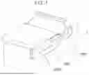
FIG. 1 shows a stored state of an example of a foldable table.
FIG. 2 shows a deployed state of the foldable table.
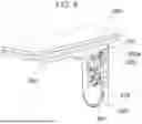
FIG. 3 is an exploded view of an example of a base of the foldable table.
FIG. 4 is a perspective view of the base of the foldable table.
FIG. 5 shows an example of a table bracket.
FIGS. 6 to 8 sequentially show an example of deployment of the table bracket.
FIG. 9 shows an example of a locking plate and a second locking member.
FIGS. 10 and 11 are diagrams illustrating an example of angle adjustment of the table bracket when the table bracket is in a fixed state.
DETAILED DESCRIPTION
Hereafter, one or more implementations of the present disclosure will be described in detail with reference to the accompanying drawings and the same or similar components are given the same reference numerals regardless of the numbers of figures and are not repeatedly described.
FIG. 1 shows a stored state of an example of a foldable table, and FIG. 2 shows a deployed state of the foldable table. FIG. 3 is an exploded view of an example of a base of the foldable table. FIG. 4 is a perspective view of the base of the foldable table. FIG. 5 shows an example of a table bracket. FIGS. 6 to 8 sequentially show deployment of the table bracket. FIG. 9 shows a locking plate and a second locking member. FIG. 10 and FIG. 11 are diagrams illustrating angle adjustment of the table bracket when the table bracket is in a fixed state.
In some implementations, referring to FIG. 1 to FIG. 5, the foldable table of the present disclosure can include a table bracket 100 on which a table plate 200 is mounted. The table plate 200 is connected with a base 300 and is hinged to be rotatable in a first direction on the base 300. The table plate 200 can be coupled to be rotatable in a second direction around the table bracket 100. In some examples, the range of use of the table plate 200 can be expanded through rotation in the second direction. The table plate 200 can be fully deployed by further rotating in a third direction. For example, in an XYZ coordinate system, FIG. 2 shows the table bracket 100 extending in the X axis and the base extending in the Z axis. The rotation of the table bracket 100 from the base 300 in the first direction can be a rotation about the Y axis orthogonal to the X and Z axes. The rotation of the table plate 200 in the second direction from the table bracket 100 can be a rotation about the Z axis perpendicular to the table plate 200. The rotation in the third direction of the table plate 200 can be a folding/unfolding of the table plate 200 about the X axis. In addition, the base 300 can rotate about the X axis.
In some examples, the table bracket 100 is rotatably hinged to a first end of the base 300 and a bracket fixing body 310 is coupled to a second end of the base 300. The base 300 provides a deployed or stored state of the table plate 200 by rotating on the bracket fixing body 310. Though will be described below, the bracket fixing body 310 is a component that cannot be moved or rotated and only the base 300 can be rotated on the bracket fixing body 310.
In some implementations, the entire foldable table including the base 300 can be stored in a table housing T and the bracket fixing body 310 can be coupled to be fixed in the table housing T.
A locking module 500 is installed in the base 300 and is engaged with the bracket fixing body 310 by rotation of the table bracket 100, thereby serving to set and fix the angle of the table bracket 100. In detail, the locking module 500 includes a first locking member 510, and when the table bracket 100 is deployed by rotating in the first direction, the first locking member 510 engages with the bracket fixing body 310 and the base 300 can no longer be rotated, whereby the angle of the table bracket 100 is also fixed.
An angle adjustment module 600 is disposed in the locking module 500, and when an external force is applied to the angle adjustment module 600, the first locking member 510 can be disengaged from the bracket fixing body 310. When the first locking member 510 is disengaged from the bracket fixing body 410, the base 300 becomes capable of rotating in the third direction, so a user can adjust the angle of the table plate 200 by adjusting the angle of the table bracket 100 in the third direction. The angle adjustment module 600 is designed to be able to be simply operated even while the table is used. This is because the portion of the angle adjustment module 600 to which an external force is applied protrudes out of the base 300, so a user can easily reach it and apply external force.
In some implementations, the locking module 500 can further include a second locking member 521 that fixes the table bracket 100 in a deployed state by engaging with the end of the table bracket 100 when the table bracket 100 is rotated in a deployment direction. The second locking member 521 is configured to engage with the end of the table bracket 100 and serves to fix the table bracket 100 when the table bracket 100 is fully deployed. In detail, when the table bracket 100 is deployed to a target angle, the second locking member 521 engages with the end of the table bracket 100, thereby maintaining the deployed state. Accordingly, the table bracket 100 is not easily moved or folded by a force applied from the outside and maintains a stable deployed state. The second locking member 521 cooperates with the first locking member 510, so when the table plate 200 is fully deployed, the two locking member 510 and 521 enhance the fixed state of the table plate 200. That is, the first locking member 510 prevents rotation of the base 300 by engaging with the bracket fixing body 310 and the second locking member 521 engages with the end of the table bracket 100, thereby increasing the stability of the entire table plate 200.
FIG. 6 to FIG. 8 sequentially shows deployment of the table bracket. Referring to FIG. to FIG. 8, it can be seen that the first locking member 510 and the second locking member 521 fix the angle and position of the table through interlinked operation. In detail, the second locking member 521 is connected with the first locking member 510, and the first locking member 510 can fix the angle of the table bracket 100 by engaging with the bracket fixing body 310 and simultaneously the second locking member 521 can fix the table bracket 100 in the deployed state by engaging with the end of the table bracket 100. That is, the first locking member 510 is moved down and engaged with the bracket fixing body 310 by rotation of the table bracket 100 in the first direction, and the second locking member 521 is connected with the first locking member 510 and is moved down and fastened to the end of the table bracket 100, that is, a locking portion 121 by rotation of the table bracket 100 in the first direction, thereby fixing the table bracket 100 in the deployed state.
As described above, the first locking member 510 and the second locking member 521 hold the table bracket at different positions, so a double locking mechanism is applied and stability is further enhanced. For example, the second locking member 521 is additionally engaged with the locking portion 121 of the table bracket 100 with the first locking member 510 engaged with the bracket fixing body 310, where it is possible to achieve firmness at a high level that cannot be ensured through single locking. Such a double fixing system prevents the table plate 200 from easily loosening under unexpected impact or overload situations and ensures safety of a user and durability of the apparatus.
In detail, locking mechanisms of the related art are unlocked and can be unexpectedly moved when strong impacts (acceleration/deceleration) are applied, but, according to the present disclosure, the table bracket is strongly restricted by the first locking member, the second locking member, and the bracket fixing body, so the table can be maintained in the fixed state even though strong impacts are applied.
In some implementations, the angle adjustment module 600 includes a guide 610 that slides and moves up the second locking member 521 when an external force is applied, and when the second locking member 521 is moved up, the first locking member 510 is also moved up, so the first locking member 510 is separated from the bracket fixing body 310 and the angle of the table bracket 100 can be adjusted.
In detail, the guide 610 is configured to slide when an external force is applied, so the guide helps mechanical operation when a user tries to change the table angle. For example, the guide 610 can include a projection 620 and projection grooves 360 and 560 are formed at the base 300 and the locking module 500, respectively, to allow the projection 620 to protrude out of the base 300. A user can apply an external force to the guide 610 through the projection 620 protruding out of the base 300. The guide 610 has a slope 630 on the side, so when the guide 610 slides, the second locking member 521 moves up along the slope 630 of the guide 610 and the first locking member 510 connected with the second locking member 521 also moves up along the second locking member 521, whereby the first locking member 510 and the bracket fixing body 310 are disengaged. Accordingly, the base 300 becomes capable of rotating in the third direction and the table bracket 100 also becomes capable of rotating in the third direction.
Though will be described below, even though the table bracket 100 has been rotated in the deployment direction, the first locking member 510 can be temporarily separated from the bracket fixing body 310. That is, the first locking member 510 is temporarily separated from the bracket fixing body 310, so the table bracket 100 can enter the state in which the angle thereof can be adjusted, and when adjustment of the angle of the table bracket 100 is finished, the first locking member 510 is fastened back to the bracket fixing body 310, whereby the base 300 and the table bracket 100 are fixed.
In more detail, the first locking member 510 and the second locking member 521 included in the locking module 500 are described.
The first locking member 510, which is a mechanism designed to fix the table angle when the table bracket 100 is deployed, includes a locking plate 511. The first locking member 510 includes the locking plate 511 that slides upward inside the locking module 500 by rotation of the table bracket 100, and a first locking gear 511a is formed at the lower end of the locking plate 511. A second locking gear 310b is formed at the upper end of the bracket fixing body 310, so the angle of the table bracket 100 is fixed by engaging the two gears 511a and 310b. That is, when the table bracket 100 is rotated in the deployment direction, the locking plate 511 of the first locking member 510 slides downward, whereby the first locking gear 511a and the second locking gear 310b of the bracket fixing body 310 are engaged and the table bracket 100 is fixed. On the contrary, when the table bracket 100 is rotated in the folding direction, the first locking member 510 is disengaged from the second locking gear 310b, and the base 300 and the table bracket 100 become capable of rotating.
The locking module 500 further includes a locking link 530 that slides inside the locking module 500 when the table bracket 100 is rotated, and the locking plate 511 is coupled to the locking link 530 through a first elastic member 512 at the lower end 530b of the locking link 530. A first end 150a of the bracket link 150 is coupled to the lower end of the table bracket 100 and a second end 150b of the bracket link 150 is supported by the middle portion 530c of the locking link 530. When the table bracket 100 is rotated in the deployment direction, the bracket link 150 presses the locking link 530 downward, whereby the locking plate 511 can be slid downward. For example, the first elastic member 512 can include a spring.
In some examples, the first end 150a of the bracket link 150 is coupled to the lower end of the table bracket 100 and the second end 150b of the bracket link 150 is supported by the middle portion 530c of the locking link 530. That is, the foldable table is designed in a structure in which when the table bracket 100 is rotated, the bracket link 150 can press the locking link 530 downward. This operation helps the locking plate 511 slide to an exact position by pushing the locking link 530 downward when the table bracket 100 is rotated in the deployment direction. In this process, the first elastic member 512 absorbs shock so that the locking link 530 smoothly slide, and helps the locking plate 511 be firmly fixed at a target position. The first elastic member 512 can partially contract and expand, but the first elastic member 512 maintains an expanded state when the locking plate 511 and the bracket fixing body 310 are coupled to each other. Further, the table bracket 100 is fixed.
It is possible to apply an external force to the angle adjustment module 600 to adjust the angle of the table bracket 100. That is, referring to FIG. 10 to FIG. 11, when an external force is applied to the guide 610 of the angle adjustment module 600 and the guide 610 moves up the second locking member 521, the locking plate 511 is moved up while contracting the first elastic member 512 because the locking plate 511 is connected to the second locking member 521, and the locking plate 511 and the bracket fixing body 310 are disengaged, whereby the base 300 and the table bracket 100 become capable of rotating in the third direction.
In some implementations, a link rail 700 is disposed in the base 300 to enable upward sliding of the second end 150b of the bracket link 150. The link rail 700 guides movement of the bracket link 150 and serves to provide stability and precision in the processes of deploying and folding of the table plate 200. The link rail 700 makes up-down movement of the bracket link 150 smooth so that a user can feel smooth operation when deploying or folding the table plate 200. Since the bracket link 150 stably slides along the link rail 700, the table plate 200 is moved smoothly and stably, whereby a user can more easily operate the table plate 200.
Since the second end 150b of the bracket link 150 slides along the link rail 700, horizontal and vertical stability of the table plate 200 can be ensured. That is, the link rail 700 provides a supporting force so that the position of the table is not changed even though the table vibrates or external impacts are applied thereto during use. This is an important function when the table plate 200 is used particularly in a narrow space or a space that is moving, and increase stability in the deployed state of the table plate 200.
In some implementations, the second locking member 521 can have a locking latch 521a formed at a first end to be engaged with the end of the table bracket 100 and a connecting portion 521b formed at a second end to be connected with the locking plate 511.
Referring to FIG. 9, a locking latch 521a that is engaged with the end of the table bracket 100 is formed at the first end of the second locking member 521. The locking latch 521a is stably engaged with the locking portion 121 of the table bracket 100 with the table bracket 100 deployed and serves to fix the table plate 200 such that the table plate 200 is not unexpectedly moved. This engagement maintains the table plate 200 in the fixed state even under vibration or external impacts that can be generated during use, thereby providing stability to a user.
A connecting portion 521b is formed at the second end of the second locking member 521 and is connected with the locking plate 511. Accordingly, the second locking member 521 performs an operation linked to movement of the locking plate 511. For example, when the locking plate 511 is slid up or down by an external force, the second locking member 521 is also moved up or down with the locking plate 511, thereby helping the table bracket 100 be fixed or released.
The second locking member 521 is linked with the locking plate 511, thereby providing an advantage of more firmly fixing the table bracket 100 in the deployed state. That is, when the table bracket 100 is deployed, the first locking member 510 fixes the angle of the table plate 200 and the locking latch 521a of the second locking member 521 is engaged with the locking portion 121 of the table bracket 100, thereby providing additional fixing. Accordingly, a double fixing structure is implemented, so a user can stably use the table plate 200.
In some implementations, the locking module 500 additionally includes a housing 540 and the housing 540 forms the external shape of the locking module 500 and is installed in a fixed state in the base 300. The housing 540 serves to protect and support the components disposed inside the locking module 500. The housing 540 is coupled not to be moved in the base 300 by bolts B.
The locking link 530 is coupled through a second elastic member 522 to be slidable in the housing 540. The second elastic member 522 is coupled to a projection formed at the upper end 530a of the locking link 530. The second elastic member 522 absorbs shock so that the locking link 530 can flexibly move by a certain amount in the housing 540. Further, the second elastic member 522 provides a force so that the locking link 530 can return to the exact position. Accordingly, the locking link 530 can stably slide up and down every time a user deploys or folds the table plate 200, and can return to the exact position when the table plate 200 is fixed or released.
That is, the second elastic member 522 can protect the locking link 530 by absorbing pressure that is applied to the locking link 530 by rotation of the table bracket 100 and the bracket link 150, and when the table bracket 100 is rotated back in the folding direction, the second elastic member 522 provides elasticity so that the locking link 530 returns to the initial position.
When the table bracket 100 is rotated in the deployment direction, the locking link 530 is pressed by the second end of the bracket link 150 and slides downward, whereby the second elastic member 522 is compressed between the housing 540 and the locking link 530. In this process, the first elastic member 512 is maintained in the expanded state. For example, the second elastic member 522 can include a spring.
It is possible to apply an external force to the angle adjustment module 600 to adjust the angle of the table bracket 100. That is, when an external force is applied to the guide 610 of the angle adjustment module 600 and the guide 610 moves up the second locking member 521, the locking plate 511 is moved up while contracting the first elastic member 512 because the locking plate 511 is connected to the second locking member 521, and the locking plate 511 and the bracket fixing body 310 are disengaged, whereby the base 300 and the table bracket 100 become capable of rotating in the third direction.
Although the present disclosure was described with reference to specific implementations shown in the drawings, it is apparent to those skilled in the art that the present disclosure can be changed and modified in various ways without departing from the scope of the present disclosure which is described in the following claims.
Claims
What is claimed is:1. A foldable table comprising:
a table plate;
a table bracket coupled to the table plate;
a base having a first end that is hinge-coupled to the table bracket, the base being configured to rotate about a second end of the base and comprising a bracket fixing body disposed inside the base and coupled to the second end of base;
a locking module disposed in the base, the locking module comprising a first locking member configured to set a tilt angle of the table bracket relative to the base by engaging with the bracket fixing body based on rotation of the table bracket relative to the base; and
an angle adjustment module disposed in the locking module and configured to separate the first locking member from the bracket fixing body to thereby adjust the tilt angle of the table bracket in response to an external force being applied to the angle adjustment module.
2. The foldable table of claim 1, wherein the locking module further comprises a second locking member configured to fix the table bracket in a deployed state by engaging with an end of the table bracket in response to the table bracket rotating to a deployment direction.
3. The foldable table of claim 2, wherein the second locking member is connected with the first locking member, and
wherein the first locking member is configured to set the tilt angle of the table bracket by engaging with the bracket fixing body at a time point at which the second locking member fixes the table bracket in the deployed state by engaging with the end of the table bracket.
4. The foldable table of claim 3, wherein the angle adjustment module comprises a guide configured to guide the second locking member to move upward in response to the external force, and
wherein the first locking member is configured to move upward the bracket fixing body in response to the second locking member moving upward such that the first locking member is separated from the bracket fixing body to thereby allow the tilt angle of the table bracket to be adjusted.
5. The foldable table of claim 2, wherein the first locking member comprises:
a locking plate configured to slide upward based on rotation of the table bracket; and
a first locking gear defined at a lower end of the locking plate,
wherein the bracket fixing body defines a second locking gear at an upper end thereof, and
wherein the first locking gear and the second locking gear are configured to engage with each other based on rotation of the table bracket in the deployment direction to thereby set the tilt angle of the table bracket.
6. The foldable table of claim 5, wherein the locking module further comprises:
a locking link configured to move inside the locking module in response to rotation of the table bracket; and
a first elastic member disposed at a lower end of the locking link, wherein the locking plate is coupled to the locking link through the first elastic member,
wherein the table bracket comprises a bracket link having (i) a first end coupled to a lower end of the table bracket and (ii) a second end supported by a middle portion of the locking link, and
wherein the bracket link is configured to, in response to rotation of the table bracket in the deployment direction, press the locking link downward to thereby move the locking plate downward.
7. The foldable table of claim 5, wherein the second locking member has (i) a first end that defines a locking latch configured to engage with the end of the table bracket and (ii) a second end that defines a connecting portion configured to connect to the locking plate.
8. The foldable table of claim 7, wherein the locking latch is configured to, in response to the locking plate moving downward, engage with the end of the table bracket and fix the table bracket in the deployed state.
9. The foldable table of claim 6, wherein the locking module further comprises:
a housing that defines an external shape of the locking module and is fixed in the base; and
a second elastic member,
wherein the locking link is coupled through the second elastic member and configured to be slidable in the housing.
10. The foldable table of claim 9, wherein the second elastic member is configured to, in response to the table bracket rotating in the deployment direction, be compressed between the housing and the locking link in a state in which the first elastic member is maintained in an expanded state.
11. The foldable table of claim 10, wherein the angle adjustment module comprises a guide configured to guide the second locking member to move upward in response to the external force, and
wherein the locking plate is configured to, in response to the second locking member moving upward, move upward while compressing the first elastic member to thereby allow the first locking gear and the second locking gear to be disengaged from each other.
12. The foldable table of claim 6, wherein the base comprises a link rail disposed therein and configured to guide the second end of the bracket link to move up and down.
13. The foldable table of claim 1, wherein the bracket fixing body is coupled to a table housing, and
wherein the base and the table bracket are configured to be stored in the table housing.
14. The foldable table of claim 13, wherein the foldable table is configured to (i) be deployed from the table housing based on the base rotating about the bracket fixing body in an upward direction, and (ii) be folded into the table housing based on the base rotating about the bracket fixing body in a downward direction.
Images & Drawings included:


Sources:
- United States Patent and Trademark Office - verify current appl. status at the USPTO↗
Similar patent applications:
- » 20100175594
Foldable table and a foldable bench - » 20210345785
Foldable side table for a collapsible chair and a combination collapsible chair with a foldable side table - » 16029268
Apparatuses and methods for creating foldable tables for ready assembly - » 13694182
Foldable table - » 10434720
Foldable table - » 14155326
Foldable table with stacking arrangement - » 15223425
Seat with integrated foldable table - » 15062600
Foldable table - » 15833872
Integrated foldable table and bench assembly - » 10434698
Foldable table with four bar link
Recent applications in this class:
- » 20220117389 2022-04-21
Multi-place dining table for a vehicle - » 20220095785 2022-03-31
SLIDE-OUT TRAY TABLE WITH INTERLOCK ASSEMBLY - » 20200345132 2020-11-05
Utility table apparatus and method - » 20200237092 2020-07-30
Inner organ for a vehicle, having a retractable shelf - » 20190320791 2019-10-24
Multifunctional folding table - » 20180110323 2018-04-26
Folding table - » 20160331125 2016-11-17
Wall Mounted Deployable Furniture Piece - » 20150351528 2015-12-10
Table arrangement - » 20150282608 2015-10-08
Folding table - » 20120199051 2012-08-09
Self-tensioning drive belt system