COLLAPSIBLE CHAISE
US20260144375A1
2026-05-28
18/961,920
2024-11-27
Smart Summary: A collapsible chaise is a type of lounge chair that can be easily folded up. It has two long legs that are connected by special hinges that lock in place. A cross-member helps keep the legs open when in use. When it's time to pack it away, the hinges can be released, allowing the legs to fold in. This design makes it simple to transport, store, and ship the chaise. 🚀 TL;DR
Abstract:
A collapsible chaise is disclosed. The collapsible chaise includes two elongated legs attached via at least one locking hinge on each side of the chaise. In addition, a collapsible, transverse cross-member secures the legs in an open position. When the locking hinges are disengaged and the collapsible transverse cross-member is disengaged, the two elongated legs can collapse inward toward the underside of the chaise on a plurality of hinges to enable the chaise to collapse for easier transport, storage, and shipping.
Applicant:
Interested in similar patents?
Get notified when new applications in this technology area are published.
Classification:
A47C1/143 » CPC main
Chairs adapted for special purposes; Beach chairs ; Chairs for outdoor use, e.g. chairs for relaxation or sun-tanning Chaise lounges
A47C1/14 IPC
Chairs adapted for special purposes Beach chairs ; Chairs for outdoor use, e.g. chairs for relaxation or sun-tanning
Description
NOTICE OF COPYRIGHTS AND TRADE DRESS
A portion of the disclosure of this patent document contains material which is subject to copyright protection. This patent document may show and/or describe matter which is or may become trade dress of the owner. The copyright and trade dress owner has no objection to the facsimile reproduction by anyone of the patent disclosure as it appears in the Patent and Trademark Office patent files or records, but otherwise reserves all copyright and trade dress rights whatsoever.
BACKGROUND
Field
The field of the invention is chairs and recliners.
This disclosure relates to a collapsible chaise chair that may fold flat by folding legs from the sides. For stability, the chaise may include a separate rigid transverse support structure between the legs and/or locking hinges to ensure the legs stay perpendicular to the chaise body. The chaise may include an integrated side table.
Description of the Related Art
Chaises and chaise chairs exist. Common chaises have an extended leg-support area to support the extended legs of the user and an adjustable back-support area to support the back and head of the user. The back-support area is commonly adjustable to allow a seated position with the back vertical or nearly vertical, a fully reclined position, or a number of positions in between. Some of these chaises have fixed lower portions while others are entirely collapsible.
Common outdoor chaises also have a number of legs to support the leg-support area and back-support area off the ground. Some outdoor chaises may have legs that fold to flatten the chaise for storage or transport. Generally, each of the legs fold independently, or from front-to-back to maintain a rigid transverse support structure between the legs. Commonly, these type chaises have a tri-fold upper structure with two or three independent legs underneath, each typically at a pivot point (e.g. the pivot for the head and upper body, the pivot for the lower legs area). However, as most have experienced, these types of portable or collapsible chaises tend to be very unstable, rickety and prone to breaking. They are also often quite heavy and bulky in transport, either in shipping or in the back of a car for a weekend getaway.
Most outdoor chaises do not have integrated side tables. Instead, if the user of a chaise wants a table upon which to place a drink, book, or other paraphernalia, a separate side table must be used.
THE DRAWINGS
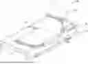
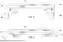
FIG. 1 is a top, perspective view of the chaise.
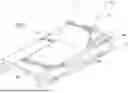
FIG. 2 is a bottom, perspective view of the chaise.
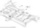
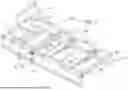
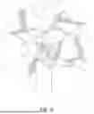
FIG. 3 is a bottom, perspective view of the chaise showing movement of a collapsible cross-member.
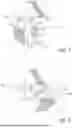
FIG. 4 is an elevation view of the chaise from a distal end showing the elongated legs in an extended position.
FIG. 5 is an elevation view of the chaise from a distal end showing the elongated legs collapsed.
FIG. 6 is a detailed perspective view of a locking hinge.
FIG. 7 is a detailed side view of the locking hinge with the elongated legs in the extended position.
FIG. 8 is a detailed side view of the locking hinge with the elongated legs in the collapsed position.
DETAILED DESCRIPTION
The collapsible chaise described herein solves numerous problems with the prior art. The collapsible chaise disclosed herein is extremely strong and sturdy, yet light. The frame and collapsible legs are typically manufactured from extruded aluminum (steel or other materials may be used). The cross members are therefore very light, and very strong. However, these members are almost entirely hollow, and therefore do not use much material, are not heavy, and do not need significant reinforcing structure.
The collapsible chaise is stable and sturdy through the use of locking hinges on the collapsible legs and a transverse collapsible cross-member that both ensure that the legs of the chaise cannot inadvertently collapse inward, potentially injuring someone. Significant, intentional effort is required to collapse the chaise as shown below.
Finally, because the legs collapse inward, the collapsible chaise, when in a collapsed position, has a very limited top-to-bottom cross section. It can fold down to less than four inches in thickness from top to bottom. This is significant in that these chaises may be shipped in flatpack containers with very highly efficient use of space in containers. In addition, after purchase, a user may store many of these chaises (e.g. for winter or when not in use) in a much more compact overall space by collapsing them, and then stacking them one on another.
This is accomplished without the overall flimsiness and instability present in many other collapsible chaise chairs. The rigid, locking hinges and transverse cross-member provide a user with a sense of strength and stability in the design, while still enabling the very efficient use of space.
Wheels are provided to enable easy movement of the chaise when not collapsed and tilted, but the wheels are positioned such that the chaise will not inadvertently move when in use.
Accordingly, the addition of collapsible legs that fold in from the side, a separate rigid transverse support structure and an integrated side table, are new advances in chaises and the subject of considerable innovation.
Description of Apparatus
A collapsible chaise particularly useful for outdoor use and subsequent storage is described herein. The chaise may include legs that fold in from the side to fold the chaise flat, it may include a separate rigid transverse cross-member and locking hinges for stability, and it may include an integrated side table for convenience.
Turning to FIG. 1, a top, perspective view of the chaise 100 is shown. The chaise is composed of several components. Shown are fixed lower portion 102, adjustable upper portion 104, a frame 106, a pair of elongated legs 108 (only one visible from this angle), each made up of three legs 112, 112′, 112″ and an elongated leg base 113, a transverse, collapsible cross-member 110, an angle adjustment mechanism 114 for the adjustable upper portion 104, and a table portion 116.
The lower portion 102 and adjustable upper portion 104 form the chaise, with the lower portion 102 forming a plane upon which a human may be supported. The lower portion 102 may be made of any fabric, metal, rattan, plastic, or other material sufficiently supportive to ensure a typical human body may be supported.
The adjustable upper portion 104 is movable along an arc using the adjustment mechanism 114. These types of mechanisms, typically with a series of catches at regular intervals, may hold the adjustable upper portion 104 in place at various angles from co-planar with the lower portion 102 to nearly or actually perpendicular to the lower portion 102. Other types of adjustment mechanism 114 may be mechanical, electrical, or pneumatic.
A lower portion 102 and adjustable upper portion 104 may be composed of fabric, however, other suitable materials known in the art, such as mesh fabric, or plastic mesh, may be used. The adjustable upper portion 104 may be supported by two arms with a cross bar to form the adjustment mechanism 114. The arms may swing freely and the cross bar may engage with a number of stops arranged below the adjustable upper portion 104 (when the adjustable upper portion 104 is in a reclined position.), thereby supporting the adjustable upper portion 104 at a variety of angles, depending on which stops the cross bar engages with. In this figure an integrated side table is disposed to the left of the lower portion 102 and adjustable upper portion 104.
The frame 106 is a rectangular portion of the chaise that surrounds the lower portion 102 and upper portion 104 and provides a base structure to support the table portion 116 as well. In some embodiments, the table portion 116 may not be present or may take a wider or narrower shape or not take up the entirety of the chaise 100 length. The frame 106 is preferably manufactured of extruded aluminum, but other metals, plastics, wood or other materials may be used. The frame 106 also supports the adjustment mechanism 114.
The elongated leg 108 (another is present on the non-visible side) is made up of three legs 112, 112′, and 112″ and an elongated leg base 113. More or fewer than three legs 112, 112′, and 112″ could be used. And, the elongated leg base 113 may be made up of one or more portions or sub-components. However, the single-piece construction does add strength and ease of manufacture to the design. Each of the elongated legs 108 is preferably manufactured of extruded aluminum that is hollow. But, other materials such as various plastics, metals, or wood may likewise be used.
The table 116 supports the overall rigidity of the chaise 100 and provides a location to support a drink, a book, or other object desirable to be kept near to a user of the chaise 100. The integrated table 116 may run the length of the chaise 100. However, in other embodiments the integrated table 116 may be disposed to the right of the lower portion 102 and adjustable upper portion 104. Furthermore, in some embodiments the table 116 may not run the entire length of the chaise 100. The integrated side table may be composed of metal, wood, plastic, fabric, mesh, plastic mesh, or another material known in the art. Furthermore, the integrated table 116 may be divided into two or more sections, and each section may be composed of the same or different materials. Yet additional embodiments may omit an integrated table 116.
Shown attached between the elongated legs 108 is a transverse, collapsible cross-member 110 that connects legs 112′ on each side. As will be described more fully in subsequent views, the transverse, collapsible cross-member 110 may be capable of disengaging from a middle right leg and middle left leg, swinging freely to either the front or back of the chaise 100. In so doing, the two elongated legs 108 can fold in from the sides to collapse and flatten the chaise 100. Although shown at ground level and even with legs 112′, the transverse, collapsible cross-member 110 may connect the elongated legs 108 at any height or other location along the elongated legs 108. Furthermore, although the collapsible cross-member 110 is shown connecting the pair of legs 112′, it may connect any or all other legs 112, 112″ present in a particular chaise 100. Furthermore, a chaise 100 may have multiple collapsible cross-members 110 connecting multiple of the legs 112, 112′, and 112″.
In some cases, an additional reclining chaise may be joined to the overall chase 100 across the table 116 such that two chases are side-by-side with the table 116 therebetween. In such a case, one or more transverse, collapsible cross-members 110 may be present to provide additional horizontal structural integrity. One may be placed in substantially the same location as the one shown in FIG. 1, perpendicular to leg 112′. But, another may be placed closer to the foot of the chaise at a regular interval in the same general location, perpendicular to the elongated legs 108. An additional leg 112″′ (not shown) may be present at a location between the leg 112′ and 112″ to provide further vertical support for such a double-chaise. Each collapsible cross-member 110 may be collapsible in much the same way, by rotating it toward the foot or head of the chaise 100 to thereby cause it to rest flush against a plane formed by the frame 106.
Turning to FIG. 2, a bottom, perspective view of the chaise 100 is shown. The table 116 shown is divided into two sections, one adjacent to the lower portion 102, another adjacent to the upper portion 104, with each section is composed of a different material. Visible from this perspective are one of the arms and cross bar that form the adjustment mechanism 114 that supports the adjustable upper portion 104. The cross bar is engaged with two stops to support the adjustable upper portion 104 in a semi-reclined position. Shown are a plurality of stops, however, other embodiments may use any number of stops to enable various inclinations of recline for the adjustable upper portion. Yet other embodiments may use other technologies known in the art to provide support for the back-support area in at least one inclination. The stops are connected to stop-support bars connected to the frame 108. Each of the legs 112, 112′ and 112″ are shown along with an elongated leg base 113 to form the elongated legs 108.
Visible in this view are the transverse, collapsible cross-member 110, a locking hinge 118, and a clip 120 with which the collapsible cross-member 110 may engage. The collapsible cross-member 110 engages with both of the elongated legs 108 to ensure that neither of the elongated legs 108 may collapse inward while the cross-member 110 is engaged with the clip 120. This clip may frictionally engage each end of the collapsible, cross-member 110 to retain it in position until affirmatively removed by a person. Other attachment mechanisms may be used, other than the clip 120, including spring-mounted pins, channels into which portions of the cross-member 120 may sit unless disengaged, and other locking or semi-locking mechanisms known in the art. The cross-member 110 provides structural support and rigidity to the overall chaise 100 when in place like this.
The cross-member 110 is further comprised of two (or more) arms which are connected to the bottom of the frame using a hinge such that the transverse, collapsing cross-member 110 structure may rotate about the connection points when it is unclipped or otherwise disengaged from the elongated legs. When pivoted (or rotated), the cross-member 110 enables the chaise 100 to be collapsed for storage and transport. The cross-member 110 may be mounted to a fixed cross member above (not numbered) within the plane of the lower portion 104. The cross-member 110 is preferably made of aluminum as well, but may be made of steel or other suitably strong material to provide structural rigidity and resist inadvertent collapse of the chaise 100.
Likewise, though not visible in this view, the hinges 118 are locking hinges that must be disengaged. In this way, two systems for ensuring that the chaise 100 does not collapse unless a user engages in that process are provided. The locking hinges 118 must be disengaged, preferably with a lever, before the elongated legs 108 may be collapsed inward.
FIG. 3 is a bottom, perspective view of the chaise 100 showing movement of the collapsible, cross-member 110. The discussion provided with respect to elements present in prior figures will not be repeated here. In FIG. 3, the collapsible, cross-member 110 has been disengaged (e.g. unclipped) and pivoted forward and toward the front of the chaise 100. It may be mounted with a friction-based hinge such that it remains in this position unless acted upon by an outside force to enable a user to easily fold the chaise 100. This folding creates sufficient space for the elongated legs, particularly legs 112′ to collapse inward from each side of the chaise and to flatten against the bottom of the chaise 110 substantially parallel to a plane formed by the frame 106 and/or the lower portion 104. In other embodiments the collapsible, cross-member 110 may pivot up and to the front of the chaise. In addition, in other embodiments there may be a plurality of rigid transverse support structures connecting a plurality of pairs of legs 112, 112′, and 112″. In other cases, the transverse, collapsible cross-member 110 may pivot forward or backward relative to the front or back of the chaise 100.
FIG. 4 is an elevation view of the chaise from a distal end showing elongated legs 108, 108′ in an extended position. In this view the collapsible, cross-member 110 has rotated up and to the back of the chaise. The elongated legs 108 and 108′ are therefore free to collapse inward from each side and flatten against the bottom of the chaise 100. Locking hinges 118, and 118′ are visible in this figure as well.
FIG. 5 is an elevation view of the chaise 100 from a distal end showing the elongated legs 108, 108′ collapsed. In this view the collapsible, cross-member 110 has pivoted up and to the back of the chaise 100. In addition, the elongated legs 108 and 108′ and legs 112, 112′ and 112″ (not visible) have rotated in from the sides to flatten against the bottom of the chaise. Locking hinges 118, and 118′ are visible in this figure as well.
FIG. 6 is a detailed perspective view of a locking hinge 118. The locking hinge 118 has an upper portion 120 and a lower portion 122 along with a lever 124 to disengage the locking portion. The lever 124 is preferably spring-loaded such that inadvertent release of the locking hinge 118 is very unlikely. The operation of the locking hinge 118 will be discussed more fully with respect to FIGS. 7 and 8 below.
FIGS. 7 and 8 are detailed side view of the locking hinge 118 with the elongated legs 108 in the extended position and in the collapsed position. Both figures will be referred to simultaneously herein below. The locking hinge 118 is capable of locking at least one of the legs 112, 112′, and 112″ (see FIG. 2) into a vertical position when the chaise 100 is in use or ready for use. The locking hinge 118 is capable of locking the elongated legs 108 into a horizontal position when the chaise 100 is flattened for storage or ready for storage or transport.
The locking hinge 118 includes two indentation 126, 128 which receive one of two pegs 130, 132. When the peg 130 is locked into the vertical indentation 126 the elongated leg 108 is locked into a vertical orientation. When the peg 130 is locked into the horizontal indentation 128 the elongated leg 108 is locked into a horizontal orientation. The peg 130 may be unlocked from either indentation and rotated with the elongated leg 108 so that the peg 130 engages with the other indentation 126, 128 and may be locked into that new orientation.
The locking hinge 118 is spring loaded such that the peg 130 are biased toward the indentations 126, 128. In turn, peg 132 is biased toward peg 130 via an internal spring structure. In such a way, the peg 130 defaults to staying within one of the indentations 126, 128 unless acted upon by user interaction with the lever, which relies upon peg 132 as a lever to pull peg 130 out of the indentations 126, 128. The internal spring (or springs) may be countered through user interaction with the lever 124 to thereby move both pegs 130, 132 away from a pivot point of the lockable hinge 118. The peg 132 is used as a guide for movement of peg 130 as a user applies force to lever 124. Other lockable hinges known in the art may also be used. It is preferrable to use a single locking hinge 118 on each elongated leg 108, but in some cases, multiple locking hinges may be used.
The indentations 126, 128 are shown here as having sharp edges. Such a configuration is possible and suitable, but it may be preferrable for the edges of the indentations 126, 128 to be slightly-rounded to allow for easier entry and exit of the pegs 130, 132. The trade off in ease of entry and exit is a slightly less-fixed locking hinge 118. In different cases, it may be preferrable to have the edges be very sharp, while in others it may be preferrable for the edges to be more rounded to be simpler for the user to move from locked to unlocked configurations of the locking hinge 118.
Closing Comments
Throughout this description, the embodiments and examples shown should be considered as exemplars, rather than limitations on the apparatus and procedures disclosed or claimed. Acts, elements and features discussed only in connection with one embodiment are not intended to be excluded from a similar role in other embodiments.
As used herein, “plurality” means two or more. As used herein, a “set” of items may include one or more of such items. As used herein, whether in the written description or the claims, the terms “comprising”, “including”, “carrying”, “having”, “containing”, “involving”, and the like are to be understood to be open-ended, i.e., to mean including but not limited to. Only the transitional phrases “consisting of” and “consisting essentially of”, respectively, are closed or semi-closed transitional phrases with respect to claims. Use of ordinal terms such as “first”, “second”, “third”, etc., in the claims to modify a claim element does not by itself connote any priority, precedence, or order of one claim element over another or the temporal order in which acts of a method are performed, but are used merely as labels to distinguish one claim element having a certain name from another element having a same name (but for use of the ordinal term) to distinguish the claim elements. As used herein, “and/or” means that the listed items are alternatives, but the alternatives also include any combination of the listed items.
Claims
It is claimed:1. A collapsible chaise comprising:
a rectangular frame having two longer sides and two shorter sides, the frame comprising a fixed lower portion forming a plane connecting the two long sides and one of the two short sides and an adjustable upper portion;
a pair of elongated legs, joined to the underside of the rectangular frame, along the two longer sides thereof;
at least two locking hinges joining the pair of elongated legs to the underside of the rectangular frame; and
wherein engagement of the locking hinges in a first position causes the pair of elongated legs to remain fixed, substantially perpendicular to the plane of the rectangular frame, and disengagement of the locking hinges causes the pair of elongated legs to collapse inward, toward the underside of the plane along the two long sides of the rectangular frame.
2. The collapsible chaise of claim 1 wherein engagement of the locking hinges in a second position causes the pair of elongated legs to remain fixed, substantially parallel to the plane of the rectangular frame in a position along the underside of the plane.
3. The collapsible chaise of claim 1 wherein the adjustable upper portion is movable from a position co-planar with the plane to a position at an obtuse angle from the plane.
4. The collapsible chaise of claim 1 further comprising a collapsible cross-member, wherein in an engaged position, the collapsible cross-member provides frictional force against at least one of the elongated legs to prevent the elongated legs from collapsing inward, toward the underside of the plane and wherein in a disengaged position, the collapsible cross-member enables the elongated legs to collapse inward, toward the underside of the plane.
5. The collapsible chaise of claim 1 wherein each of the pair of elongated legs comprises:
at least three legs, extending downward from the rectangular frame;
an elongated leg base, parallel to one of the two longer sides of the rectangular frame and attached at a distal end of each of the at least three legs.
6. The collapsible chaise of claim 5 further comprising a collapsible cross-member, wherein in an engaged position, the collapsible cross-member provides a frictional force against at least one of the at least three legs to prevent the elongated legs from collapsing inward, toward the underside of the plane, and wherein in a disengaged position, the collapsible cross-member moves removing the frictional force and enables the elongated legs to collapse inward, toward the underside of the plane.
7. The collapsible chaise of claim 1 wherein the plane and the adjustable upper portion each comprise a cover, suitable for supporting the weight of a human.
8. The collapsible chaise of claim 1 further comprising a table portion, the table portion co-planar with and adjacent to the plane within the rectangular frame.
9. A collapsible chaise comprising:
a rectangular frame having two longer sides and two shorter sides, the frame comprising a fixed lower portion forming a plane connecting the two long sides and one of the two short sides and an adjustable upper portion;
a pair of elongated legs, joined to the underside of the rectangular frame, along the two longer sides thereof;
a collapsible cross-member, wherein in an engaged position, the collapsible cross-member provides frictional force against at least one of the elongated legs to prevent the elongated legs from collapsing inward, toward the underside of the plane, and wherein in a disengaged position, the collapsible cross-member enables the elongated legs to collapse inward, toward the underside of the plane; and
wherein engagement of the collapsible cross-member with the pair of elongated legs in the engaged position causes the elongated legs to remain fixed, substantially perpendicular to the plane of the rectangular frame, and disengagement of the collapsible cross-member in the second position causes the pair of elongated legs to collapse inward, toward the underside of the plane along the two long sides of the rectangular frame.
10. The collapsible chaise of claim 9 wherein the adjustable upper portion is movable from a position co-planar with the plane to a position at an obtuse angle from the plane.
11. The collapsible chaise of claim 1 wherein the collapsible cross-member pivots approximately ninety degrees on a hinged attachment point fixed to the underside of the frame to move from the engaged position to the disengaged position.
12. The collapsible chaise of claim 9 wherein each of the pair of elongated legs comprises:
at least three legs, extending downward from the rectangular frame;
an elongated leg base, parallel to one of the two longer sides of the rectangular frame and attached at a distal end of each of the at least three legs.
13. The collapsible chaise of claim 12 further comprising a collapsible cross-member, wherein in the first position, the collapsible cross-member provides frictional force against at least one of the at least three legs to prevent the elongated legs from collapsing inward, toward the underside of the plane and wherein in a second position, the collapsible cross-member moves to a position that removes the frictional force and enables the elongated legs to collapse inward, toward the underside of the plane.
14. The collapsible chaise of claim 9 further comprising at least two locking hinges joining the pair of elongated legs to the underside of the rectangular frame.
15. The collapsible chaise of claim 14 wherein engagement of the locking hinges in a first position causes the pair of elongated legs to remain fixed, substantially perpendicular to the plane of the rectangular frame, and disengagement of the locking hinges causes the pair of elongated legs to collapse inward, toward the underside of the plane along the two long sides of the rectangular frame.
16. The collapsible chaise of claim 15 wherein engagement of the locking hinges in a second position causes the pair of elongated legs to remain fixed, substantially parallel to the plane of the rectangular frame in a position along the underside of the plane.
17. The collapsible chaise of claim 9 wherein the plane and the adjustable upper portion each comprise a cover, suitable for supporting the weight of a human.
18. The collapsible chaise of claim 9 further comprising a table portion, the table portion co-planar with and adjacent to the plane within the rectangular frame.
19. A collapsible chaise comprising:
a rectangular frame having two longer sides and two shorter sides, the frame comprising a fixed lower portion forming a plane connecting the two long sides and one of the two short sides and an adjustable upper portion;
a pair of elongated legs, joined to the underside of the rectangular frame, along the two longer sides thereof, the elongated legs formed of:
at least four leg portions attached by hinges and extending outward from an underside of the rectangular frame, and
a pair of elongated leg bases, fixed to a base of the at least two leg portions opposite of the hinges, wherein at least two of the hinges are locking hinges joining at least two of the at least four leg portions of elongated legs to the underside of the rectangular frame;
wherein engagement of the locking hinges in a first position causes the pair of elongated legs to remain fixed, substantially perpendicular to the plane of the rectangular frame, and disengagement of the locking hinges causes the pair of elongated legs to collapse inward, toward the underside of the plane along the two long sides of the rectangular frame; and
a collapsible cross-member, wherein in an engaged position, the collapsible cross-member provides a frictional force against at least one of the at least three legs to prevent the elongated legs from collapsing inward, toward the underside of the plane, and wherein in a disengaged position, the collapsible cross-member moves removing the frictional force and enabling the elongated legs to collapse inward, toward the underside of the plane.
20. The collapsible chaise of claim 19 wherein the plane and the adjustable upper portion each comprise a cover, suitable for supporting the weight of a human.
Images & Drawings included:
Sources:
- United States Patent and Trademark Office - verify current appl. status at the USPTO↗
Recent applications in this class:
- » 20260020673 2026-01-22
MULTIFUNCTIONAL LOUNGE CHAIR ASSEMBLY - » 20250351964 2025-11-20
FURNITURE WEIGHT SYSTEMS AND METHODS - » 20250318645 2025-10-16
MODULAR OUTDOOR FURNITURE - » 20250134257 2025-05-01
ROTATABLE SUNTANNING CHAIR DEVICE - » 20240138570 2024-05-02
Lounge Chair Cushion Device - » 20240008648 2024-01-11
CHAISE LOUNGE - » 20230363535 2023-11-16
CHAISE LOUNGE WITH QUICK RELEASE - » 20230000252 2023-01-05
Orthopedic lounge chair - » 20220322830 2022-10-13
Sliding Lounger - » 20200069062 2020-03-05
EZ Handles