Puzzle Table
US20260145053A1
2026-05-28
19/185,296
2025-04-22
Smart Summary: A puzzle table is a piece of furniture designed for assembling puzzles. It has a sturdy frame and a tabletop that includes a special middle section. This middle section features a cavity for placing puzzle pieces and a drawer that can rotate out for easy access. The drawer can be locked in place when closed to keep everything secure. This design makes it convenient for puzzle lovers to work on their projects without losing pieces. 🚀 TL;DR
Abstract:
The present invention relates to the technical field of furniture products, and particularly to a puzzle table. A puzzle table comprises a table frame and a tabletop assembly mounted on the table frame. The tabletop assembly includes a middle frame unit and a table board. The middle frame unit has a placement cavity and a drawer unit. The drawer unit is rotationally connected to the middle frame unit via a rotating member, enabling the drawer unit to rotate outward or retract relative to the rotating member. The rotating member is positioned on an outer side edge of the drawer unit near a corner. The drawer unit has a fixed edge, and a locking mechanism is provided between the fixed edge and the placement cavity to lock the drawer unit upon being closed.
Applicant:
Interested in similar patents?
Get notified when new applications in this technology area are published.
Classification:
A63F9/1044 » CPC main
Games not otherwise provided for; Patience; Other games for self-amusement; Two-dimensional jig-saw puzzles Display boards therefor
A47B25/00 » CPC further
Card tables; Tables for other games
A47B88/40 » CPC further
Drawers for tables, cabinets or like furniture; Guides for drawers Sliding drawers; Slides or guides therefor
A63F2009/105 » CPC further
Games not otherwise provided for; Patience; Other games for self-amusement; Two-dimensional jig-saw puzzles; Display boards therefor with provisions for storing and transporting an interrupted game
A63F9/10 IPC
Games not otherwise provided for; Patience; Other games for self-amusement Two-dimensional jig-saw puzzles
Description
CROSS-REFERENCE TO RELATED APPLICATIONS
The application claims priority to Chinese patent application No. 202422901735.3, filed on Nov. 27, 2024, and to Chinese patent application No. 202422902403.7, filed on Nov. 27, 2024, the entire contents of which are incorporated herein by reference.
TECHNICAL FIELD
The present invention relates to the technical field of furniture products, and particularly to a puzzle table.
BACKGROUND ART
A puzzle table is a specially designed table for assembling puzzles, featuring multiple functional and convenient characteristics aimed at providing users with a comfortable, tidy, and enjoyable puzzle-solving experience. In existing puzzle table designs, the tabletop is typically used solely for displaying and assembling puzzles, lacking storage functionality. Additionally, while some storage puzzle tables with drawers are available on the market—allowing users to store partially assembled puzzle pieces in the drawers to prevent loss—in most designs, opening and closing mechanisms of drawers are relatively simplistic, primarily employing linear sliding mechanism.
However, the following drawbacks have been identified in the aforementioned drawer structures during use:
-
- 1: The linear sliding mechanism requires sufficient front-to-back clearance, often restricting internal space utilization and leaving certain areas underutilized. Moreover, for larger tabletops, straight-pull drawers located on both sides of the desktop require sufficient front-and-rear clearance when fully extended, forcing users to stand up and move to the side of the table to access it fully, thereby increasing inconvenience.
- 2: Many tabletops are designed to tilt or flip relative to the frame for angle adjustment. However, when the user needs to adjust the desktop angle or position, such tilting or flipping motions may inadvertently cause the drawer to slide open, leading to the spillage of stored items.
SUMMARY OF THE INVENTION
To address the issues mentioned in the prior art, the present invention provides a puzzle table.
The technical solution adopted by the present invention to solve the technical problems is as follows: a puzzle table includes a table frame and a tabletop assembly mounted on the table frame. The tabletop assembly includes a middle frame unit and a table board installed within the middle frame unit. The middle frame unit has a placement cavity and at least one drawer unit disposed within the placement cavity. The drawer unit is rotationally connected to the middle frame unit via a rotating member, enabling the drawer unit to rotate outward or retract relative to the rotating member. The rotating member is positioned on an outer side edge of the drawer unit near a corner and is rotationally connected to the side edge of the middle frame unit. The drawer unit has a fixed edge located on a side of the drawer unit close to the rotating member, and a locking mechanism is provided between the fixed edge and the placement cavity to lock the drawer unit upon being closed.
By adopting the above technical solution, the drawer unit is rotationally connected to the middle frame unit via the rotating member, allowing the drawer unit to rotate outward or retract relative to the rotating member. This avoids the front-to-back clearance required by linear sliding mechanisms and optimizes internal drawer space utilization by positioning the rotating member on an outer side edge of the drawer unit near a corner. Additionally, the locking mechanism prevents accidental sliding of the drawer unit.
Further, the locking mechanism includes a first magnetic portion fixed on the fixed edge and a second magnetic portion fixed on a corresponding position of a side wall of the placement cavity. The first magnetic portion can magnetically adhere to the second magnetic portion for locking and disengage for unlocking upon being rotated outward.
By adopting this solution, when the drawer unit is closed, the second magnetic portion in the placement cavity attracts the first magnetic portion on the fixed edge of the drawer unit, achieving secure locking.
Further, the locking mechanism comprises a T-shaped block threadedly connected to the fixed edge and a perforation provided on the side wall of the placement cavity, the perforation being adapted to allow the T-shaped block to pass through upon being rotated and pushed in. The T-shaped block can rotate to form a cross structure with the perforation for locking.
By adopting this solution, when the drawer unit is closed, the T-shaped block extends through the perforation. Rotating the T-shaped block forms a cross structure with edges of the perforation, effectively preventing the T-shaped block from disengaging and ensuring stable locking.
Further, the locking mechanism is a spring snap self-locking mechanism, including a movable engaging portion fixed on the fixed edge and a fixed engaging portion on the side wall of the placement cavity. The movable engaging portion can apply a rotational force to the fixed engaging portion for locking the movable engaging portion and release the movable engaging portion from the fixed engaging portion upon reapplication of force.
By adopting this solution, when rotating and retracting the drawer unit, the movable engaging portion contacts and applies a force to the fixed engaging portion located in the placement cavity, enabling to engage the movable engaging portion and achieving locking. Upon unlocking, applying force from the outer side of the drawer unit enbale the fixed engaging portion to release the movable engaging portion to achieve locking.
Further, the table frame includes multiple telescopic legs and support rods connecting tops of adjacent telescopic legs. Each telescopic leg has a fixed portion and a movable portion. A first crossbeam is provided between adjacent fixed portions, and a second crossbeam is provided between adjacent movable portions. The first crossbeam is connected to a sleeve, while the second crossbeam is connected to a movable member movably inserted into the sleeve. A side wall of the movable member is provided with a positioning portion, and a side wall of the sleeve is vertically arranged with a elongated moving hole. Along a side of the elongated moving hole is arranged with multiple positioning holes. Each positioning hole communicates with the elongated moving hole. The positioning portion can slide along the moveable elongated hole as the movable portion rises, locking into any positioning hole. The top of the moveable elongated hole has a reset zone, allowing the positioning portion to rise into the reset zone and then fall back to the lowest point.
By adopting this solution, when adjusting the table frame to a desired height by lifting the movable portion of the telescopic legs up and down relative to the fixed portion, the positioning portion of the movable member moves up with the movable portion and is engaged and positioned into the positioning hole of the sleeve, ensuring stability at a position of the adjusted height and preventing accidental sinking. The reset zone arranged at the top of the moveable elongated hole allows the telescopic legs to return to the lowest position when raised to the maximum height.
Further, one side of the tabletop assembly is hinged to the table frame, and a support mechanism is provided between the tabletop assembly and the table frame to support and fix the tabletop assembly at different angles. The support mechanism includes a positioning bracket and multiple positioning grooves spaced on the table frame. One end of the positioning bracket is hinged to the tabletop assembly, while the other end can engage with different positioning grooves.
By adopting this solution, the hinged connection between one side of the tabletop assembly and the table frame allows the tabletop assembly to tilt and adjust the angle, and engaging the positioning bracket with different grooves supports and fixes the positioning bracket at various angles.
Further, the support mechanism includes two gas springs between the tabletop assembly and the table frame, one side of each gas spring hinged to both sides of the tabletop assembly and the other side of each gas spring hinged to both sides of the table frame.
By adopting this solution, the self-locking property of the gas springs ensures and achieves fixing, enables the tabletop assembly not to falling off and fixes the tabletop assembly at the desired angle stably.
Further, the support mechanism includes two hinge brackets between the tabletop assembly and the table frame, one side of each hinge bracket hinged to both sides of the tabletop assembly and the other side of each hinge bracket hinged to both sides of the table frame.
By adopting this solution, the hinge brackets restrict the tilting angle of the tabletop assembly while fixing the tabletop assembly at the desired angle, enhancing adjustability and stability of the tabletop assembly.
Further, the drawer unit has an arc-shaped edge, located on a side of the drawer unit far away from the rotating member.
By adopting this solution, the side of the drawer unit far away from the rotating member has a arc-shaped edge, which can reduce collision risks during rotation, opening and closing of the drawer unit with the middle frame unit.
A top surface of the middle frame unit is provided with an installation slot to accommodate the table board, which is detachably mounted into the installation slot. Multiple elastic retaining pieces are spaced along a side wall of the installation slot to secure the table board.
By adopting this solution, the table board is detachably installed in the middle frame unit and elastic retaining pieces are used to secure the table board, facilitating assembly and disassembly for transportation.
In summary, beneficial effects of the present invention are as follows:
-
- 1. The rotating member connects an outer side edge near a corner of the drawer unit to a corresponding position of the middle frame unit, enabling rotation-based extension/retraction the of the drawer unit from the middle frame unit relative to the rotating member and due to the positioning the rotating member at the corner of the drawer unit, maximizing a rotating radius of the drawer unit, and utilizing an internal space of the drawer unit effectively.
- 2. The present invention prevents the drawer unit from accidentally sliding out during table movement by incorporating the fixed edge on the drawer unit and adding the locking mechanism between the fixed edge and the installation cavity.
- 3. The present invention incorporates multiple telescopic legs in the table frame, each including the movable portion and the fixed portion, where the movable portion is vertically adjustable within the fixed portion to enable a height adjustment of the table frame. Moreover, the first crossbeam, the second crossbeam, the sleeve and the movable member are provided between the fixed portions and movable portions respectively. The engagement of the movable member with the movable cavity within the sleeve and the design of positioning holes and positioning portion ensures a stability during height adjustment of the desk frame while preventing unintended descent of the table frame.
- 4. The present invention enables angle tilting adjustment of the desktop member through a hinged connection between the side of the desktop member and the table frame. A support mechanism integrated between the components ensures stable tilt positioning, preventing unintended return.
The above description is only an overview of the technical solutions of the present invention. To better understand the technical means of the invention, implementation can be carried out according to the contents of the specification. To make the above and other objectives, features, and advantages of the invention more apparent, preferred embodiments are provided below with accompanying drawings for detailed explanation.
BRIEF DESCRIPTION OF THE DRAWINGS
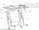
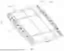
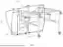
FIG. 1 is a schematic structural diagram of the embodiment.
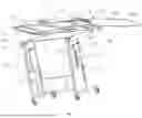
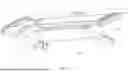
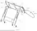
FIG. 2 is a schematic diagram of the drawer unit in the retracted state in this embodiment.
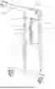
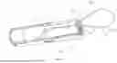
FIG. 3 is a schematic diagram of the telescopic legs in this embodiment.
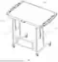
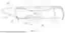
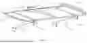
FIG. 4 is a schematic diagram of the middle frame unit in this embodiment.
FIG. 5 is a schematic diagram of the support structure in Embodiment 1.
FIG. 6 is a schematic diagram of the locking mechanism in Embodiment 1.
FIG. 7 is a schematic diagram of the locking mechanism in Embodiment 2.
FIG. 8 is a schematic diagram of the locking mechanism in Embodiment 3.
FIG. 9 is an enlarged schematic diagram of the support mechanism in Embodiment 4.
FIG. 10 is an enlarged schematic diagram of the support mechanism in Embodiment 5.
In the drawings: 1-Table frame; 11-Telescopic leg; 111-Movable portion; 112-Fixed portion; 12-Support rod; 13-First crossbeam; 14 Second crossbeam; 15-Sleeve; 16-Movable member; 161-Positioning portion; 17-Elongated moving hole; 18-Positioning hole; 19-Reset area; 2-Tabletop assembly; 21-Middle frame unit; 211-Installation slot; 212-Elastic retaining piece; 22-Placement cavity; 23-Table board; 24-Drawer unit; 241-Fixed edge; 242-Arc-shaped edge; 25 Rotating member; 3-Locking mechanism; 31-First magnetic portion; 32-Second magnetic portion; 33-T-shaped block; 34-Perforation; 35 Movable engaging portion; 36-Fixed engaging portion; 4-Support mechanism; 41-Positioning bracket; 42-Positioning groove; 43-Gas spring; 44-Hinge bracket.
DETAILED DESCRIPTION OF THE INVENTION
To facilitate a clearer understanding of the content of the present invention, the following further elaborates on the invention based on specific embodiments and accompanying drawings.
It should be noted that the terms “center,” “upper,” “lower,” “front,” “rear,” “left,” “right,” “inner,” “outer,” etc., used herein indicate orientations or positional relationships based on those shown in the drawings. These terms are used solely for ease of description and simplification, rather than implying that the referenced device or component must have a specific orientation or be constructed and operated in a particular orientation. Therefore, they should not be construed as limiting the invention. Unless otherwise specified, “a plurality” means two or more.
Unless explicitly defined otherwise, terms such as “install,” “connect,” and “couple” should be interpreted broadly. For example, connections may be fixed, detachable, or integral; connections may be mechanical or electrical; connections may be direct or indirect via an intermediary; or connections may be internal connections between two components. Those of ordinary skill in the art can understand the specific meanings of these terms in the context of the present invention based on the actual circumstances.
EMBODIMENT 1
As shown in FIGS. 1 to 10, this embodiment provides a puzzle table, which includes a table frame 1 and a tabletop assembly 2 mounted on the table frame 1. The tabletop assembly 2 includes a middle frame unit 21 and a table board 23 installed within the middle frame unit 21. The middle frame unit 21 has a placement cavity 22 and at least one drawer unit 24 disposed within the placement cavity 22. The drawer unit 24 is rotationally connected to the middle frame unit 21 via a rotating member 25, enabling the drawer unit 24 to rotate outward or retract relative to the rotating member 25. The rotating member 25 is positioned on an outer side edge of the drawer unit 24 near a corner and is rotationally connected to a side edge of the middle frame unit 21. The drawer unit 24 has a fixed edge 241 located on a side of the drawer unit 24 close to the rotating member 25, and a locking mechanism 3 is provided between the fixed edge 241 and the placement cavity 22 to lock the drawer unit 24 when closed.
The table frame 1 serves as a supporting structure and may be either a fixed table frame 1 or a height-adjustable table frame 1. The tabletop assembly 2 at the top of the table frame 1 includes the middle frame unit 21, the table board 23, and the drawer unit 24. The middle frame unit 21 acts as a frame surrounding the table board 23, with the placement cavity 22 inside serving as an installation space for the drawer unit 24. Two drawer units 24 are arranged inside the placement cavity 22 and on the left and right sides of the placement cavity 22, fully occupying a space of the placement cavity 22. Specifically, openings are provided on left and right sides of the middle frame unit 21 to allow the drawer units 24 to extend outward from the area of the middle frame unit 21. Additionally, a thickness of the middle frame unit 21 may be increased to accommodate multi-layered drawer units 24 in the area of both sides if needed. Each drawer unit 24 is internally divided into multiple puzzle compartments for storing puzzle pieces. The rotating member 25 provided between the drawer unit 24 and the middle frame unit 21 may be a rotating shaft or ball joint. This connection allows the drawer unit 24 to rotate around the central axis of the rotating member 25 for rotating outward or retracting. The rotating member 25 is specifically positioned at the outer side edge of the drawer unit near the corner close to the front side of the user and connected to a corresponding position of the side opening of the middle frame unit 21, maximizing a rotation radius of the drawer unit 24. Specifically, a handle is fixed on the outer side edge of the drawer unit 24. when the drawer is needed to extract outward, the user simply uses the hand to pull the handle from the side edge in an arc-shaped motion, causing the drawer unit 24 to rotate around the central axis of the rotating member 25 and extract outward in a maximum degree, facilitating access to the puzzle pieces inside the drawer unit 24. Conversely, applying a pushing force from the side edge the retracts the drawer unit 24 back into the placement cavity 22 in a rotating direction. Since the rotating member 25 is positioned near the front side of the user, the drawer can be operated without standing up.
Furthermore, the drawer unit 24 has a fixed edge 241, the fixed edge 241 is specifically provided near a side edge of the rotating member 25. When the drawer unit 24 is rotatably retracted, the fixed edge 241 rests against an inner wall of the placement cavity 22. The locking mechanism 3 is installed between the fixed edge 241 and the inner wall of the placement cavity 22. When the drawer unit 24 is in a retracting state and the fixed edge 241 rests against an inner wall of the placement cavity 22, the he locking mechanism 3 between the fixed edge 241 and the inner wall of the placement cavity 22 locks the drawer unit 24, to ensures the drawer remains securely closed.
As shown in FIG. 6, the locking mechanism 3 in this embodiment includes a first magnetic portion 31 fixed on the fixed edge 241 and a second magnetic portion 32 fixed on the corresponding position of the side wall of the placement cavity. The first magnetic portion 31 and the second magnetic portion 32 magnetically adhere to lock the drawer and separate to unlock when rotated outward. Specifically, a magnet is fixed on the side of the end face of the fixed edge 241 far away from the rotating member 25, serving as the first magnetic portion 31, while another magnet attracting the above magnet is fixed at a corresponding position of the placement cavity 22, serving as the second magnetic portion 32. When the drawer unit 24 is closed, the fixed edge 241 abuts against the inner wall of the placement cavity with the rotating movement. At this time, the first magnetic portion 31 will attract the second magnetic portion 32 to lock the drawer unit 24, preventing accidental opening. The magnetic force is weak enough to allow easy unlocking between the first magnetic portion 31 will attract the second magnetic portion 32 with minimal user effort.
As shown in FIGS. 1 and 3, the table frame 1 includes multiple telescopic legs 11 and support rods 12 connecting the tops of adjacent telescopic legs 11. Each telescopic leg 11 includes a fixed portion 112 and a movable portion 111. A first crossbeam 13 is provided between adjacent fixed portions 112, while a second crossbeam 14 is provided between adjacent movable portions 111. The first crossbeam 13 is connected to a sleeve 15, and the second crossbeam 14 is connected to a movable member 16 slidably inserted into the sleeve 15. A positioning portion 161 is provided on a side wall of the movable member 16, and an elongated moving hole 17 is vertically arranged on a side wall of the sleeve 15. Multiple positioning holes 18 are spaced along the elongated moving hole 17, each positioning hole connected to the elongated moving hole 17. The positioning portion 161 slides along the elongated moving hole 17 as the movable portion 111 rises, locking into any positioning hole 18. A reset area 19 at the top of the elongated moving hole 17 allows the positioning portion 161 to rise into the reset area 19 and then fall back to the lowest point. Among them, the table frame 1 mainly includes a frame body, and the frame body includes four telescopic legs 11. These four telescopic legs 11 are respectively located at the four corners of the table frame 1, forming a stable rectangular framework. Each telescopic leg 11 is divided into a fixed portion 112 and a movable portion 111. The movable portion 111 can move up and down inside the fixed portion 112, thereby achieving height adjustment of the table frame 1. To enhance structural stability and adjustment functionality, a first crossbeam 13 is provided between the fixed portions 112 on adjacent sides of any two parallel surfaces to fixedly connect the fixed portions 112 on both sides. A sleeve 15 is connected to the first crossbeam 13. The sleeve 15 has an internal movable cavity with an upward-facing opening. Correspondingly, a second crossbeam 14 is provided between the movable portions 111 on the corresponding side. A movable member 16 which is downward provided is connected to the second crossbeam 14. The movable member 16 is shaped as an elongated rectangular strip and is slidably inserted into the aforementioned movable cavity. When the movable portion 111 moves up and down relative to the fixed portion 112, the movable member 16 also moves up and down within the movable cavity. A width of the movable member 16 is slightly narrower than that of the movable cavity, allowing the movable member 16 to move vertically while permitting a certain degree of lateral adjustment. Furthermore, elongated moving holes 17 are vertically provided on both sides of the sleeve 15. On the corresponding sides of the movable member 16, positioning protrusions serving as positioning portions 161 are provided, which can move along the elongated slots. On one side of each elongated moving hole 17, multiple positioning holes 18 at different heights are arranged, all of which communicate with the elongated moving hole 17. A cross-section of each positioning hole 18 is semi-heart-shaped, and an arc-shaped surface is formed between adjacent positioning holes 18. The bottom of each positioning hole 18 has a groove, allowing the positioning portion 161 to slide into the positioning hole 18 when moving along the elongated moving hole 17, thereby forming a lock to prevent sinking after being lifted upward. Additionally, a reset zone 19 is reserved at the top of the elongated moving hole 17, where no positioning holes 18 are provided on the side of reset zone 19. When the movable member 16 rises to the reset zone 19 along with the movable portion 111 of the telescopic leg 11, the positioning portion 161 is not locked by any positioning hole 18 on the side, causing the movable member 16 to automatically return to the lowest point, completing the reset.
As shown in FIGS. 1 and 5, one side of the tabletop assembly 2 is hinged to the table frame 1, and a support mechanism 4 is provided between the tabletop assembly 2 and the table frame 1 to fix the tabletop assembly 2 at different angles. The support mechanism 4 includes a positioning bracket 41 and multiple positioning grooves 42 spaced on the table frame 1. One end of the positioning bracket 41 is hinged to the tabletop assembly 2, while the other end of the positioning bracket 41 can engage with different positioning grooves 42. Specifically, the side facing the user of the middle frame unit 21 of the desktop component 2 is hinged to the corresponding side of the top end face of the table frame 1, allowing the user to flip and adjust the angle of the desktop component 2. Additionally, a positioning bracket 41 is hinged to both sides of the bottom of the middle frame of the desktop component 2, while multiple positioning grooves 42 are arranged longitudinally at intervals on both sides of the support rod 12 at the top of the table frame 1. By inserting the other end of the positioning bracket 41 into different positioning grooves 42, the user can open or close the desktop component 2 to various angles and secure the desktop component 2 in position.
As shown in FIG. 1, the drawer unit 24 has an arc-shaped edge 242 on the side far away from the rotating member 25. Specifically, the drawer unit 24 in this embodiment is designed with three edges. An outer edge is equipped with a rotating member 25, which aligns with side profiles of the middle frame unit 21 on both sides, ensuring structural aesthetics. The edge opposite to the rotating member 25 adopts a curved design, significantly reducing the risk of collision between the drawer and the middle frame during rotational opening and closing.
As shown in FIG. 4, the top surface of the middle frame unit 21 is provided with an installation slot 211 to accommodate the table board 23. The table board 23 is detachably mounted in the installation slot 211, with the sidewalls of the installation slot 211 spaced with multiple elastic retaining pieces 212 for securing the table board 23. The size of the installation slot 211 matches that of the table board 23, allowing the table board 23 to be easily placed into the installation slot 211 on the top surface of the middle frame unit 21. Multiple elastic retaining pieces 212 are spaced along side walls of the installation slot 211, particularly at each corner, to provide preliminary positioning and fixation of the table board 23. When removing the table board 23, only a slight force is needed to overcome a resistance of the elastic retaining pieces 212, allowing for easy extraction. Alternatively, clamping slots or snap fasteners can be provided on the sidewalls of the installation slot 211 in the middle frame unit 21, with corresponding snap fasteners or clamping slots on the table board 23, to achieve fixation through engagement of the snap fasteners and clamping slots.
EMBODIMENT 2
This embodiment differs from Embodiment 1 in the locking mechanism 3 and unlocking method. As shown in FIG. 7, specifically, the locking mechanism 3 in this embodiment includes a T-shaped block 33 threadedly connected to the fixed edge 241, and a perforation 34 provided on the side wall of the accommodation cavity 22 and adapted to the T-shaped block 33 to allow the passage of the locking mechanism 3 during rotational advancement. The T-shaped block 33 can be rotated to form a cross-shaped interlocking structure with the perforation 34 for locking. The T-shaped block 33 is made of metal or other high-strength materials to ensure durability. A shape of the T-shaped block 33 resembles the letter “T,” featuring a rectangular head and a cylindrical shaft. The end of the shaft is provided with a threaded portion, while the fixed edge 241 is provided with a matching threaded hole for threaded connection. A perforation 34 matching the head of the T-shaped block 33 is provided at a corresponding position of the side wall of the accommodation cavity 22. This perforation 34 is linear in shape, allowing the T-shaped block 33 to pass through when the drawer unit 24 is closed. To lock, the T-shaped block 33 is rotated from the outer side wall of the middle frame unit 21, causing the head of the T-shaped block 33 to form a cross-shaped interlocking structure with edges of the perforation 34. This effectively prevents the T-shaped block 33 from disengaging from the perforation 34, achieving a stable locking effect. The remaining structure and effects of this embodiment are consistent with those of Embodiment 1 and will not be reiterated here.
EMBODIMENT 3
This embodiment differs from Embodiment 1 in the locking mechanism 3 and unlocking method. As shown in FIG. 8, specifically, the locking mechanism 3 is a spring snap self-locking mechanism, including a movable engaging portion 35 on the fixed edge 241 and a fixed engaging portion 36 on the side wall of the placement cavity. The movable engaging portion 35 can apply rotational force to the fixed engaging portion 36 to lock the movable engaging portion 35, and upon reapplication of force, the movable engaging portion 35 can be unlocked from the fixed engaging portion 36. In this embodiment, the movable engaging portion 35 includes a lock housing fixedly mounted to the sidewall of the middle frame unit 21. The lock housing is internally provided with a lock groove and a push rod capable of sliding along the lock groove. One end of the push rod is connected to a spring, while the other end is connected to a female lock clasp, with a slot formed between the female lock clasps. The fixed engaging portion 36 is a male lock clasp fixedly mounted to the fixed edge 241. When the drawer unit 24 is rotated to close, the male lock clasp gradually approaches the female lock clasp. Upon contact, the front end of the male lock clasp inserts into the slot between the female lock clasps, pushing the female lock clasp inward. This, in turn, drives the push rod to slide along the track, overcoming an initial counterforce of the spring. Meanwhile, the locking portions on both sides of the female lock clasp move closer to those of the male lock clasp until the locking portions on both sides of the female lock clasp and the locking portions of the male lock clasp engage, completing the locked state. To open the drawer unit 24, the outer edge of the drawer unit 24 is simply pressed. This action transmits force to the fixed engaging portion 36 i.e., the male lock clasp on the fixed edge 241. The pressure causes the male lock clasp to exert a reverse force on the female lock clasp, pushing the female lock clasp further inward against the spring force until the locking engagement is released, allowing the drawer unit 24 to rotate open. Once the external force is removed, the female lock clasp automatically resets under the restoring force of the spring, preparing for the next locking operation. The remaining structure and effects of this embodiment are consistent with those of Embodiment 1 and will not be repeated here.
EMBODIMENT 4
This embodiment differs from Embodiment 1 in the support mechanism 4 and unlocking method. As shown in FIG. 9, specifically, the support mechanism 4 includes two gas springs 43 between the tabletop assembly 2 and table frame 1. One end of each gas spring 43 is hinged to both sides of the desktop assembly 2 and at the other end of each gas spring 43 to both sides of the table frame 1. Specifically, the gas spring 43 is a self-locking gas spring 43. One end of the gas spring 43 is fixed to the side furface of the desktop assembly 2 via a hinge component such as a hinge or ball stud, while the other end of the gas spring 43 is similarly fixed to the side of the table frame 1 via a hinge component. When adjusting the desktop assembly 2 to the desired angle by flipping desktop assembly 2, the self-locking feature of the gas spring 43 ensures fixation, preventing unintended retraction and allowing stable positioning at the required angle. Other structures and effects of this embodiment are consistent with those of Embodiment 1 and will not be repeated here.
EMBODIMENT 5
This embodiment differs from Embodiment 1 in the support mechanism 4 and unlocking method. As shown in FIG. 10, specifically, the support mechanism 4 includes two hinge brackets 44 between the tabletop assembly 2 and table frame 1. One end of is hinged to both sides of the desktop assembly 2 and the other end of the hinge bracket 44 is hinged to both sides of the table frame 1. Specifically, the support mechanism 4 in this embodiment consists of two hinge brackets 44 respectively arranged between both sides of the table frame 1 and the desktop assembly 2. The hinge bracket 44 specifically includes: a sleeve rod hinged to the side of the table frame 1, and a support arm hinged to the side of the desktop assembly 2. The support arm is inserted into the sleeve rod and can slide relative to the sleeve. Multiple stop holes are arranged inside the cavity of the sleeve rod, while a stop protrusion is provided on the side of the movable end of the support arm. When users adjust the desktop assembly 2 to an appropriate angle, the stop protrusion can engage with corresponding stop holes inside the sleeve rod, thereby fixing the support arm at a specific position and ensuring the stability of the desktop assembly 2 at different angles. The remaining structure and effects of this embodiment are consistent with those of Embodiment 1 and will not be repeated here.
In summary, the beneficial effects of this embodiment are as follows: the embodiment provides an innovative puzzle table design. By arranging rotating members 25 at the outer side edge of the drawer unit 24 near the corner and corresponding positions on the middle frame unit 21, the drawer unit 24 can be rotated out from or retracted into the middle frame unit 21, maximizing the rotation radius of the drawer unit 24 and rationally utilizing the internal space of the drawer. Simultaneously, the fixed edge 241 is provided on the drawer unit 24, and a locking mechanism 3 is added between the fixed edge 241 and the accommodation cavity 22, effectively preventing the risk of accidental sliding out of the drawer unit 24 during table movement. Additionally, the table frame 1 is designed with telescopic legs 11 including movable portions 111 and fixed porttions 112. The movable portions 111 can move vertically within the fixed portions 112 to achieve height adjustment of the table frame 1. To ensure stability during height adjustment, the first crossbeams 13 and the second crossbeams 14 are arranged between the fixed portons 112 and movable porttions 111 respectively, along with sleeves 15 and movable members 16. Through the cooperation between the movable members 16 and the movable cavity inside the sleeve 15, as well as the design of positioning holes 18 and positioning portionts 161, accidental sinking of the table frame 1 is prevented. Finally, one side of the desktop assembly 2 is hinged to the table frame 1, supporting angle adjustment and flipping of the desktop assembly 2 relative to the table frame 1. Combined with the support mechanism 4 between the desktop assembly 2 and the table frame 1, the stability of the desktop assembly 2 at tilted angles is ensured, preventing unintended retraction.
The above embodiments are merely preferred implementations of the invention and do not limit the scope of the invention. Any non-substantive modifications made by those skilled in the art based on the invention fall within the scope of protection.
Claims
What is claimed is:1. A puzzle table comprising a table frame and a tabletop assembly disposed on the table frame, wherein the tabletop assembly comprises a middle frame unit and a table board installed within the middle frame unit, the middle frame unit having a placement cavity and at least one drawer unit disposed within the placement cavity, the drawer unit is rotationally connected to the middle frame unit via a rotating member, enabling the drawer unit to rotate outward or retract relative to the rotating member, the rotating member is disposed on an outer side edge of the drawer unit near a corner and rotationally connected to a side edge of the middle frame unit;
the drawer unit has a fixed edge, the fixed edge is located on a side of the drawer unit close to the rotating member, and a locking mechanism is provided between the fixed edge and the placement cavity to lock the drawer unit upon being closed.
2. The puzzle table according to claim 1, wherein the locking mechanism comprises a first magnetic portion fixed on the fixed edge and a second magnetic portion fixed at the corresponding position of the side wall of the placement cavity, the first magnetic portion is capable of magnetically adhering to the second magnetic portion for locking and disengaging for unlocking upon being rotated outward.
3. The puzzle table according to claim 1, wherein the locking mechanism comprises a T-shaped block threadedly connected to the fixed edge and a perforation provided on the side wall of the placement cavity and adapted to the T-shaped block for allowing the T-shaped block to pass through upon being rotated and pushed in, the T-shaped block is capable of rotating to form a cross structure with the perforation for locking.
4. The puzzle table according to claim 1, wherein the locking mechanism is a spring snap self-locking mechanism, comprising a movable engaging portion fixed on the fixed edge and a fixed engaging portion provided on the side wall of the placement cavity, the movable engaging portion is capable of applying rotational force to the fixed engaging portion to lock the movable engaging portion and releasing the movable engaging portion from the fixed engaging portion upon reapplication of force.
5. The puzzle table according to claim 1, wherein the table frame comprises multiple telescopic legs and support rods connecting tops of adjacent telescopic legs, each telescopic leg have a fixed portion and a movable portion, a first crossbeam is provided between adjacent fixed portions, and a second crossbeam is provided between adjacent movable portions, the first crossbeam is connected with a sleeve, the second crossbeam is connected with a movable member slidably inserted into the sleeve, the side wall of the movable member is provided with a positioning portion, the side wall of the sleeve is vertically provided with an elongated moving hole, along the side of the elongated moving hole is provided with multiple positioning holes, each positioning hole is connected to the elongated moving hole, the positioning portion is capable of sliding along the elongated moving hole as the movable portion rises to lock into any positioning hole, the top of the elongated moving hole is provided with a reset area where the positioning portion can rise and then fall back to the lowest point.
6. The puzzle table according to claim 1, wherein one side of the tabletop assembly is hinged to the table frame, and a support mechanism is provided between the tabletop assembly and the table frame to support the tabletop assembly at different angles, the support mechanism comprises a positioning bracket and multiple positioning grooves spaced apart on the table frame, one end of the positioning bracket is hinged to the tabletop assembly and the other end of the positioning bracket is capable of engaging with different positioning grooves.
7. The puzzle table according to claim 6, wherein the support mechanism comprises two gas springs disposed between the tabletop assembly and the table frame, one end of each gas spring is hinged to both sides of the tabletop assembly and the other end of each gas spring is hinged to both sides of the table frame.
8. The puzzle table according to claim 6, wherein the support mechanism comprises two hinge brackets disposed between the tabletop assembly and the table frame, one end of each hinge bracket is hinged to both sides of the tabletop assembly and the other end of each hinge bracket is hinged to both sides of the table frame.
9. The puzzle table according to claim 1, wherein the drawer unit further has an arc-shaped edge, the arc-shaped edge is located on the side of the drawer unit away from the rotating member.
10. The puzzle table according to claim 1, wherein a top surface of the middle frame unit is provided with an installation slot for accommodating the table board, the table board is detachably installed in the installation slot, along a side wall of the installation slot is provided with multiple elastic retaining pieces spaced apart for fixing the table board.
Images & Drawings included:
Sources:
- United States Patent and Trademark Office - verify current appl. status at the USPTO↗
Similar patent applications:
- » 20250312687
SPLICED PUZZLE TABLE - » 17573650
Adjustable multidimensional jigsaw puzzle table - » 18764239
Jigsaw puzzle table - » 19030643
Liftable and rotatable jigsaw puzzle table - » 19037343
Rotation member prevented from being entangled, and jigsaw puzzle table - » 19204361
Jigsaw puzzle table - » 20070039523
Jigsaw puzzle table - » 20230347235
PUZZLE TABLE AND TABLE BOARD THEREOF - » 20240325874
Jigsaw puzzle table - » 20240416220
JIGSAW PUZZLE TABLE
Recent applications in this class:
- » 20260027452 2026-01-29
REINFORCED MULTIFUNCTIONAL JIGSAW PUZZLE TRAY - » 20260027451 2026-01-29
JIGSAW PUZZLE BOARD TURNTABLE - » 20250312687 2025-10-09
SPLICED PUZZLE TABLE - » 20250312686 2025-10-09
PUZZLE PLATFORM - » 20250312685 2025-10-09
WALL MOUNTED JIGSAW PUZZLE WORK SURFACE AND STORAGE SYSTEM - » 20250262524 2025-08-21
ROTATING ASSEMBLY AND JIGSAW PUZZLE TABLE - » 20250256203 2025-08-14
MOVABLE PUZZLE PLATFORM - » 20250229169 2025-07-17
PUZZLE TABLE - » 20250186878 2025-06-12
MAGIC CUBE JIGSAW FRAME FOR SEAMLESS SPLICING - » 20250135326 2025-05-01
PUZZLE PLATFORM