WAX TRAY APPARATUS AND RELATED SYSTEMS AND METHODS
US20260145833A1
2026-05-28
18/957,556
2024-11-22
Smart Summary: A new tray design helps in making blocks of wax. The tray has a compartment with four walls and a bottom. Three of the walls rise at the same angle, while the back wall rises at a steeper angle. This unique shape allows for better wax formation. Overall, it simplifies the process of creating wax blocks. 🚀 TL;DR
Abstract:
Wax devices and methods are disclosed for creating blocks of wax. A wax block tray may include a first compartment including a left side wall, a front side wall, a right side wall, a rear side wall, and a bottom surface. The left side wall may extend upwardly away from the bottom surface toward an upper end of the left side wall at a first angle. The front side wall may extend upwardly away from the bottom surface toward an upper end of the front side wall at the first angle. The right side wall may extend upwardly away from the bottom surface toward an upper end of the right side wall at the first angle. The rear side wall may extend upwardly away from the bottom surface toward an upper end of the rear side wall at a second angle, the second angle being greater than the first angle.
Assignee:
- Nhi Pham Enterprise, LLC 4 🇺🇸 Houston, TX, United States
Applicant:
Interested in similar patents?
Get notified when new applications in this technology area are published.
Classification:
B65D1/36 » CPC main
Containers having bodies formed in one piece, e.g. by casting metallic material, by moulding plastics, by blowing vitreous material, by throwing ceramic material, by moulding pulped fibrous material, by deep-drawing operations performed on sheet material; Trays or like shallow containers with moulded compartments or partitions
Description
BACKGROUND OF THE INVENTIONS
1. Field of the Inventions
The present inventions generally pertain to paraffin wax, and more particularly to methods and systems for removing hardened paraffin wax from a container.
2. Description Of The Related Art
It is known that paraffin wax is used in beauty salons for cosmetic purposes to treat a person's skin. The paraffin wax is typically packaged in hand-held plastic packages that are delivered to the salon for use. The packaged paraffin wax is in a solid form, much like the consistency of a candle. When the paraffin wax is needed, the salon will cut off the plastic packaging, and then place the wax into a warmer where it is warmed into a liquid-like or flowable consistency. The wax can then be easily dipped out of the warmer and applied to the customer's skin in a known manner.
It has been determined that it would be more efficient and economical to deliver the paraffin wax to beauty salons in larger, bulk containers, such as a container around the size of a five-gallon bucket, for example. Proceeding in this fashion, however, creates a problem to be solved, namely, how to extract the hardened paraffin wax from the bulk container. The present inventions as discussed hereinbelow have been developed to address and solve this problem.
SUMMARY OF THE INVENTIONS
In one aspect, the present inventions may include a wax block forming tray comprising: a first compartment including a left side wall, a front side wall, a right side wall, a rear side wall, and a bottom surface, the left side wall extending upwardly away from the bottom surface toward an upper end of the left side wall at a first angle, the front side wall extending upwardly away from the bottom surface toward an upper end of the front side wall at the first angle, the right side wall extending upwardly away from the bottom surface toward an upper end of the right side wall at the first angle, and the rear side wall extending upwardly away from the bottom surface toward an upper end of the rear side wall at a second angle, the second angle being greater than the first angle. Another feature of this aspect of the present inventions may be that the first angle is in a range from 2 to 3 degrees. Another feature of this aspect of the present inventions may be that the second angle is in a range from 119 to 121 degrees. Another feature of this aspect of the present inventions may be that the second angle is in a range from 115 to 125 degrees. Another feature of this aspect of the present inventions may be that the second angle is in a range from 110 to 130 degrees. Another feature of this aspect of the present inventions may be that the second angle is in a range from 105 to 135 degrees. Another feature of this aspect of the present inventions may be that the second angle is in a range from 100 to 140 degrees. Another feature of this aspect of the present inventions may be that the second angle is in a range from 115 to 145 degrees. Another feature of this aspect of the present inventions may be that the second angle is in a range from 120 to 155 degrees. Another feature of this aspect of the present inventions may be that the second angle is in a range from 125 to 165 degrees. Another feature of this aspect of the present inventions may be that the second angle is in a range from 130 to 170 degrees.
In another aspect, the present inventions may include a wax block forming tray comprising: a first compartment including a left side wall, a front side wall, a right side wall, a rear side wall, and a bottom surface, the left side wall extending upwardly away from the bottom surface toward an upper end of the left side wall at a first angle, the front side wall extending upwardly away from the bottom surface toward an upper end of the front side wall at the first angle, the right side wall extending upwardly away from the bottom surface toward an upper end of the right side wall at the first angle, the rear side wall extending upwardly away from the bottom surface toward an upper end of the rear side wall at a second angle, the second angle being greater than the first angle, the first angle is in a range from 2 to 3 degrees, and the second angle is in a range from 119 to 121 degrees.
In another aspect, the present inventions may include a wax block forming tray comprising: a first compartment, a second compartment, a third compartment, and a fourth compartment, each of said compartments including a left side wall, a front side wall, a right side wall, a rear side wall, and a bottom surface; wherein with respect to the first compartment, the left side wall of the first compartment extending upwardly away from its corresponding bottom surface toward an upper end of said left side wall at a first angle, the front side wall of the first compartment extending upwardly away from its corresponding bottom surface toward an upper end of said front side wall at the first angle, the right side wall of the first compartment extending upwardly away from its corresponding bottom surface toward an upper end of said right side wall at the first angle, and the rear side wall of the first compartment extending upwardly away from its corresponding bottom surface toward an upper end of the rear side wall at a second angle, the second angle being greater than the first angle; wherein with respect to the second compartment, the left side wall of the second compartment extending upwardly away from its corresponding bottom surface toward an upper end of said left side wall at the first angle, the rear side wall of the second compartment extending upwardly away from its corresponding bottom surface toward an upper end of said rear side wall at the first angle, the right side wall of the second compartment extending upwardly away from its corresponding bottom surface toward an upper end of said right side wall at the first angle, and the front side wall of the second compartment extending upwardly away from its corresponding bottom surface toward an upper end of said front side wall at the second angle; wherein with respect to the third compartment, the left side wall of the third compartment extending upwardly away from its corresponding bottom surface toward an upper end of said left side wall at the first angle, the front side wall of the third compartment extending upwardly away from its corresponding bottom surface toward an upper end of said front side wall at the first angle, the right side wall of the third compartment extending upwardly away from its corresponding bottom surface toward an upper end of said right side wall at the first angle, and the rear side wall of the third compartment extending upwardly away from its corresponding bottom surface toward an upper end of said rear side wall at the second angle; and wherein with respect to the fourth compartment, the left side wall of the fourth compartment extending upwardly away from its corresponding bottom surface toward an upper end of said left side wall at the first angle, the rear side wall of the fourth compartment extending upwardly away from its corresponding bottom surface toward an upper end of said rear side wall at the first angle, the right side wall of the fourth compartment extending upwardly away from its corresponding bottom surface toward an upper end of said right side wall at the first angle, and the front side wall of the fourth compartment extending upwardly away from its corresponding bottom surface toward an upper end of said front side wall at the second angle. Another feature of this aspect of the present inventions may be that the second angle is in a range from 119 to 121 degrees. Another feature of this aspect of the present inventions may be that the second angle is in a range from 115 to 125 degrees. Another feature of this aspect of the present inventions may be that the second angle is in a range from 110 to 130 degrees. Another feature of this aspect of the present inventions may be that the second angle is in a range from 115 to 145 degrees. Another feature of this aspect of the present inventions may be that the second angle is in a range from 120 to 155 degrees. Another feature of this aspect of the present inventions may be that the second angle is in a range from 125 to 165 degrees.
Other features, aspects and advantages of the present inventions will become apparent from the following discussion and detailed description.
BRIEF DESCRIPTION OF THE DRAWINGS
FIG. 1 is a perspective view of a specific embodiment of the multi-compartment wax tray for use in forming molded blocks of hardened wax.
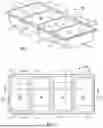
FIG. 2 a top view of the wax tray shown in FIG. 1.
FIG. 3 is a cross-section view of the wax tray shown in FIGS. 1 and 2 taken along line 3-3 of FIG. 2.
FIG. 4 is a cross-section view of the wax tray shown in FIGS. 1 and 2 taken along line 4-4 of FIG. 2.
FIG. 5 is a perspective view of the wax tray shown in FIGS. 1-4 and liquid wax being dispensed into the compartments of the wax tray.
FIG. 6 is another view of FIG. 5, but now showing the tray compartments filled with wax that has hardened.
FIG. 7 is a perspective view of the wax tray filled with hardened wax and one of the blocks of hardened wax being removed from one of the wax forming compartments.
FIG. 8 is a perspective view of a bottom side of a specific embodiment of a wax tray compartment illustrating that a logo can be part of the mold so that the resulting hardened wax blocks will have a company logo formed therein.
While the inventions will be described in connection with the preferred embodiments, it will be understood that the scope of protection is not intended to limit the inventions to those embodiments. On the contrary, the scope of protection is intended to cover all alternatives, modifications, and equivalents as may be included within the spirit and scope of the inventions as defined by the appended claims.
DETAILED DESCRIPTION OF THE INVENTION
Referring to the drawings in detail, wherein like numerals denote identical elements throughout the several views, and referring initially to FIG. 1, there is shown a perspective view of a multicompartment tray 10 for use as a mold to form hardened wax blocks. In a specific embodiment, the tray 10 may include four wax forming compartments, such as a first compartment 12, a second compartment 14, a third compartment 16, and a fourth compartment 18. In a specific embodiment, the tray 10 may include a lip 19 extending around an upper periphery of the tray 10.
In a specific embodiment, the first compartment 12 may include a left side wall 20, a front side wall 22, a right side wall 24, a rear side wall 26, and a bottom surface 28. In a specific embodiment, the left side wall 20, the front side wall 22, and the right side wall 24 may each be disposed in generally vertical planes. In a specific embodiment, each of these walls may be upwardly inclined at a first angle (preferably a slight angle) from the bottom surface 28 toward the lip 19 (or with respect to the right side wall 24, toward adjoining second compartment 14). The purpose of this first incline is to facilitate stacking of multiple trays 10 for shipping purposes. In a specific embodiment, the first angle may be in the range from 2 to 3 degrees. In a specific embodiment, the first angle may be in the range from 1 to 10 degrees. However, the present inventions are not limited to any particular number of degrees for the first angle. The other side wall, namely, the rear side wall 26, is upwardly inclined away from the bottom surface 28 toward the lip 19 at a second angle, which is greater than the first angle. The purpose of this second incline is to facilitate removal of hardened wax blocks that are formed in the tray 10. This is illustrated in FIG. 7 and further discussed below. In a specific embodiment, with reference to FIG. 4, the second angle a may be approximately 120 degrees. In a specific embodiment, the second angle may be in the range from 119 to 121 degrees. In a specific embodiment, the second angle may be in the range from 115 to 125 degrees. In a specific embodiment, the second angle may be in the range from 110 to 130 degrees. In a specific embodiment, the second angle may be in the range from 105 to 135 degrees. In a specific embodiment, the second angle may be in the range from 100 to 140 degrees. In a specific embodiment, the second angle may be in the range from 115 to 145 degrees. In a specific embodiment, the second angle may be in the range from 120 to 155 degrees. In a specific embodiment, the second angle may be in the range from 125 to 165 degrees. In a specific embodiment, the second angle may be in the range from 130 to 170 degrees. However, the present inventions are not limited to any particular number of degrees for the second angle.
In a specific embodiment, the second compartment 14 may include a left side wall 30, a front side wall 32, a right side wall 34, a rear side wall 36, and a bottom surface 38. In a specific embodiment, the left side wall 30, the rear side wall 36, and the right side wall 34 may each be disposed in generally vertical planes. In a specific embodiment, each of these walls may be upwardly inclined at a first angle (preferably a slight angle) from the bottom surface 38 toward the lip 19 (or with respect to the left side wall 30, toward the adjoining first compartment 12, and with respect to the right side wall 34, toward adjoining third compartment 16). As explained above, the purpose of this first incline is to facilitate stacking of multiple trays 10 for shipping purposes. In a specific embodiment, the first angle may be in the range from 2 to 3 degrees. In a specific embodiment, the first angle may be in the range from 1 to 10 degrees. However, the present inventions are not limited to any particular number of degrees for the first angle. The other side wall, namely, the front side wall 32, is upwardly inclined away from the bottom surface 38 toward the lip 19 at a second angle, which is greater than the first angle. The purpose of this second incline is to facilitate removal of hardened wax blocks that are formed in the tray 10. This is illustrated in FIG. 7 and further discussed below. In a specific embodiment, the second angle may be approximately 120 degrees. In a specific embodiment, the second angle may be in the range from 119 to 121 degrees. In a specific embodiment, the second angle may be in the range from 115 to 125 degrees. In a specific embodiment, the second angle may be in the range from 110 to 130 degrees. In a specific embodiment, the second angle may be in the range from 105 to 135 degrees. In a specific embodiment, the second angle may be in the range from 100 to 140 degrees. In a specific embodiment, the second angle may be in the range from 115 to 145 degrees. In a specific embodiment, the second angle may be in the range from 120 to 155 degrees. In a specific embodiment, the second angle may be in the range from 125 to 165 degrees. In a specific embodiment, the second angle may be in the range from 130 to 170 degrees. However, the present inventions are not limited to any particular number of degrees for the second angle.
In a specific embodiment, the third compartment 16 may include a left side wall 40, a front side wall 42, a right side wall 44, a rear side wall 46, and a bottom surface 48. In a specific embodiment, the left side wall 30, the front side wall 32, and the right side wall 34 may each be disposed in generally vertical planes. In a specific embodiment, each of these walls may be upwardly inclined at a first angle (preferably a slight angle) from the bottom surface 48 toward the lip 19 (or with respect to the left side wall 40, toward the adjoining second compartment 14, and with respect to the right side wall 44, toward adjoining fourth compartment 18). As explained above, the purpose of this first incline is to facilitate stacking of multiple trays 10 for shipping purposes. In a specific embodiment, the first angle may be in the range from 2 to 3 degrees. In a specific embodiment, the first angle may be in the range from 1 to 10 degrees. However, the present inventions are not limited to any particular number of degrees for the first angle. The other side wall, namely, the rear side wall 46, is upwardly inclined away from the bottom surface 48 toward the lip 19 at a second angle, which is greater than the first angle. The purpose of this second incline is to facilitate removal of hardened wax blocks that are formed in the tray 10. This is illustrated in FIG. 7 and further discussed below. In a specific embodiment, the second angle may be approximately 120 degrees. In a specific embodiment, the second angle may be in the range from 119 to 121 degrees. In a specific embodiment, the second angle may be in the range from 115 to 125 degrees. In a specific embodiment, the second angle may be in the range from 110 to 130 degrees. In a specific embodiment, the second angle may be in the range from 105 to 135 degrees. In a specific embodiment, the second angle may be in the range from 100 to 140 degrees. In a specific embodiment, the second angle may be in the range from 115 to 145 degrees. In a specific embodiment, the second angle may be in the range from 120 to 155 degrees. In a specific embodiment, the second angle may be in the range from 125 to 165 degrees. In a specific embodiment, the second angle may be in the range from 130 to 170 degrees. However, the present inventions are not limited to any particular number of degrees for the second angle.
In a specific embodiment, the fourth compartment 18 may include a left side wall 50, a front side wall 52, a right side wall 54, a rear side wall 56, and a bottom surface 58. In a specific embodiment, the left side wall 50, the rear side wall 56, and the right side wall 54 may each be disposed in generally vertical planes. In a specific embodiment, each of these walls may be upwardly inclined at a first angle (preferably a slight angle) from the bottom surface 58 toward the lip 19 (or with respect to the left side wall 50, toward the adjoining third compartment 16). As explained above, the purpose of this first incline is to facilitate stacking of multiple trays 10 for shipping purposes. In a specific embodiment, the first angle may be in the range from 2 to 3 degrees. In a specific embodiment, the first angle may be in the range from 1 to 10 degrees. However, the present inventions are not limited to any particular number of degrees for the first angle. The other side wall, namely, the front side wall 52, is upwardly inclined away from the bottom surface 58 toward the lip 19 at a second angle, which is greater than the first angle. The purpose of this second incline is to facilitate removal of hardened wax blocks that are formed in the tray 10. This is illustrated in FIG. 7 and further discussed below. In a specific embodiment, the second angle may be approximately 120 degrees. In a specific embodiment, the second angle may be in the range from 119 to 121 degrees. In a specific embodiment, the second angle may be in the range from 115 to 125 degrees. In a specific embodiment, the second angle may be in the range from 110 to 130 degrees. In a specific embodiment, the second angle may be in the range from 105 to 135 degrees. In a specific embodiment, the second angle may be in the range from 100 to 140 degrees. In a specific embodiment, the second angle may be in the range from 115 to 145 degrees. In a specific embodiment, the second angle may be in the range from 120 to 155 degrees. In a specific embodiment, the second angle may be in the range from 125 to 165 degrees. In a specific embodiment, the second angle may be in the range from 130 to 170 degrees. However, the present inventions are not limited to any particular number of degrees for the second angle.
In a specific embodiment, the tray 10 may be formed from polyethylene terephthalate material (PET), and the thickness of the material for the various parts of the tray 10 may be in the range from 1/32 to 1/16 inches. It is noted that the inclined surfaces corresponding to the second angles in the embodiment discussed above alternate from rear side wall 26, to front side wall 32, to rear side wall 46, to front side wall 52. This configuration facilitates keeping the overall tray 10 straight, stability, and even support throughout the tray 10. While the specific embodiment described above and shown in FIGS. 1-8 is a tray 10 including four wax molding compartments, the present inventions are not limited to any particular number of compartments. As shown in FIG. 8, bottom surface of the compartments may be formed with impressions of a logo or other desired image, such that the resulting hardened wax blocks with have an impression of such logo or other image.
Referring now to FIG. 5, a liquid wax dispenser 62 is shown dispensing liquid wax into the wax tray 10. Referring to FIG. 6, the wax tray 10 is shown filled with wax after the wax has hardened, and with a thin film 66 secured over the top of the tray 10. Referring now to FIG. 7, the tray 10 as shown in FIG. 6 has had the thin film 66 peeled away and removed from the top of the wax tray 10. In FIG. 7, a hand is shown with a thumb grasping an upper corner of the fourth compartment 18 of the wax tray 10 and pressing upwardly on front side wall 52 of the fourth compartment 18 to push a hardened block of wax 64 upwardly for removal from the fourth compartment 18. These blocks can then be used at salons in a known manner by melting them and then using the melted wax for use on their customers.
The present inventions provide numerous advantages over the current state of the art. Using the present inventions is more efficient and results in greater volumes of melted wax available for use in less time and with less work. This allows salons to more quickly and more efficiently serve more customers. Use of the present inventions also results in cost savings to beauty salons. Paraffin wax can be sold in bulk at prices that are far less than current paraffin wax prices for one-pound packages. Using the present inventions also reduces costs in terms of labor and handling.
It is to be understood that the inventions disclosed herein are not limited to the exact details of construction, operation, exact materials, or embodiments shown and described. Although specific embodiments of the inventions have been described, various modifications, alterations, alternative constructions, and equivalents are also encompassed within the scope of the inventions. Although the present inventions may have been described using a particular series of steps, it should be apparent to those skilled in the art that the scope of the present inventions is not limited to the described series of steps. The specification and drawings are, accordingly, to be regarded in an illustrative rather than a restrictive sense. It will be evident that additions, subtractions, deletions, and other modifications and changes may be made thereunto without departing from the broader spirit and scope of the inventions as set forth in the claims set forth below. It should also be understood that relative terms such as “upper” and “lower” and “upwardly” and “downwardly” are simply to provide frame of reference and should not be taken as limiting to any particular orientation. Accordingly, the inventions are therefore to be limited only by the scope of the appended claims. None of the claim language should be interpreted pursuant to 35 U.S.C. 112(f) unless the word “means” is recited in any of the claim language, and then only with respect to any recited “means” limitation.
Claims
1. A wax block forming tray comprising:
a first compartment including a left side wall, a front side wall, a right side wall, a rear side wall, and a bottom surface,
the left side wall extending upwardly away from the bottom surface toward an upper end of the left side wall at a first angle,
the front side wall extending upwardly away from the bottom surface toward an upper end of the front side wall at the first angle,
the right side wall extending upwardly away from the bottom surface toward an upper end of the right side wall at the first angle, and
the rear side wall extending upwardly away from the bottom surface toward an upper end of the rear side wall at a second angle, the second angle being greater than the first angle.
2. The wax block forming tray of claim 1, wherein the first angle is in a range from 2 to 3 degrees.
3. The wax block forming tray of claim 1, wherein the second angle is in a range from 119 to 121 degrees.
4. The wax block forming tray of claim 1, wherein the second angle is in a range from 115 to 125 degrees.
6. The wax block forming tray of claim 1, wherein the second angle is in a range from 110 to 130 degrees.
7. The wax block forming tray of claim 1, wherein the second angle is in a range from 105 to 135 degrees.
8. The wax block forming tray of claim 1, wherein the second angle is in a range from 100 to 140 degrees.
9. The wax block forming tray of claim 1, wherein the second angle is in a range from 115 to 145 degrees.
10. The wax block forming tray of claim 1, wherein the second angle is in a range from 120 to 155 degrees.
11. The wax block forming tray of claim 1, wherein the second angle is in a range from 125 to 165 degrees.
12. The wax block forming tray of claim 1, wherein the second angle is in a range from 130 to 170 degrees.
13. A wax block forming tray comprising:
a first compartment including a left side wall, a front side wall, a right side wall, a rear side wall, and a bottom surface,
the left side wall extending upwardly away from the bottom surface toward an upper end of the left side wall at a first angle,
the front side wall extending upwardly away from the bottom surface toward an upper end of the front side wall at the first angle,
the right side wall extending upwardly away from the bottom surface toward an upper end of the right side wall at the first angle,
the rear side wall extending upwardly away from the bottom surface toward an upper end of the rear side wall at a second angle, the second angle being greater than the first angle,
the first angle is in a range from 2 to 3 degrees, and
the second angle is in a range from 119 to 121 degrees.
14. A wax block forming tray comprising:
a first compartment, a second compartment, a third compartment, and a fourth compartment, each of said compartments including a left side wall, a front side wall, a right side wall, a rear side wall, and a bottom surface;
wherein with respect to the first compartment,
the left side wall of the first compartment extending upwardly away from its corresponding bottom surface toward an upper end of said left side wall at a first angle,
the front side wall of the first compartment extending upwardly away from its corresponding bottom surface toward an upper end of said front side wall at the first angle,
the right side wall of the first compartment extending upwardly away from its corresponding bottom surface toward an upper end of said right side wall at the first angle, and
the rear side wall of the first compartment extending upwardly away from its corresponding bottom surface toward an upper end of the rear side wall at a second angle, the second angle being greater than the first angle;
wherein with respect to the second compartment,
the left side wall of the second compartment extending upwardly away from its corresponding bottom surface toward an upper end of said left side wall at the first angle,
the rear side wall of the second compartment extending upwardly away from its corresponding bottom surface toward an upper end of said rear side wall at the first angle,
the right side wall of the second compartment extending upwardly away from its corresponding bottom surface toward an upper end of said right side wall at the first angle, and
the front side wall of the second compartment extending upwardly away from its corresponding bottom surface toward an upper end of said front side wall at the second angle;
wherein with respect to the third compartment,
the left side wall of the third compartment extending upwardly away from its corresponding bottom surface toward an upper end of said left side wall at the first angle,
the front side wall of the third compartment extending upwardly away from its corresponding bottom surface toward an upper end of said front side wall at the first angle,
the right side wall of the third compartment extending upwardly away from its corresponding bottom surface toward an upper end of said right side wall at the first angle, and
the rear side wall of the third compartment extending upwardly away from its corresponding bottom surface toward an upper end of said rear side wall at the second angle; and
wherein with respect to the fourth compartment,
the left side wall of the fourth compartment extending upwardly away from its corresponding bottom surface toward an upper end of said left side wall at the first angle,
the rear side wall of the fourth compartment extending upwardly away from its corresponding bottom surface toward an upper end of said rear side wall at the first angle,
the right side wall of the fourth compartment extending upwardly away from its corresponding bottom surface toward an upper end of said right side wall at the first angle, and
the front side wall of the fourth compartment extending upwardly away from its corresponding bottom surface toward an upper end of said front side wall at the second angle.
15. The wax block forming tray of claim 14, wherein the second angle is in a range from 119 to 121 degrees.
16. The wax block forming tray of claim 14, wherein the second angle is in a range from 115 to 125 degrees.
17. The wax block forming tray of claim 14, wherein the second angle is in a range from 110 to 130 degrees.
18. The wax block forming tray of claim 14, wherein the second angle is in a range from 115 to 145 degrees.
19. The wax block forming tray of claim 14, wherein the second angle is in a range from 120 to 155 degrees.
20. The wax block forming tray of claim 14, wherein the second angle is in a range from 125 to 165 degrees.
Images & Drawings included:


Sources:
- United States Patent and Trademark Office - verify current appl. status at the USPTO↗
Recent applications in this class:
- » 20260131930 2026-05-14
ORAL CARE SYSTEM - » 20260131929 2026-05-14
BREAST MILK STORAGE SYSTEM - » 20260109507 2026-04-23
BATTERY CELL TRAY FOR TRANSPORTING BATTERY CELL - » 20260048890 2026-02-19
ELECTRONIC DEVICE CARRIER TRAY - » 20250353637 2025-11-20
Tray Assembly - » 20250313372 2025-10-09
TRAY - » 20250304308 2025-10-02
TRAY - » 20250296723 2025-09-25
LEAK-RESISTANT TRAY AND LID - » 20250276823 2025-09-04
PACKAGING CONTAINER AND SOFT FOOD-CONTAINED PACKAGE - » 20250276822 2025-09-04
TRAY FOR HOLDING A PLURALITY OF FOOD PRODUCTS
Recent applications for this Assignee:
- » 20260145837 2026-05-28
WAX GRID APPARATUS AND RELATED SYSTEMS AND METHODS - » 20260145349 2026-05-28
WAX WIRE APPARATUS AND RELATED SYSTEMS AND METHODS - » 20250168938 2025-05-22
WAX MELTING APPARATUS AND RELATED SYSTEMS AND METHODS