SPINNING ATTACHMENT FOR A CONTAINER LID
US20260145853A1
2026-05-28
19/401,842
2025-11-26
Smart Summary: A new lid attachment can be added to beverage containers. It has a main part with a hole in the center that allows a straw to be used. There are also features on the bottom that help attach it securely to the lid. These features have ends that hold the attachment in place. The attachment can spin around the center hole without moving the lid itself. 🚀 TL;DR
Abstract:
A lid attachment for a beverage container lid that includes a main body, a plurality of attachment features, and an ornamental feature connected to the main body. The main body includes a central cavity that extends through the main body about a cavity axis. The central cavity provides access between a top side and a bottom side of the main body. The central cavity is sized to accommodate entry of a straw. The plurality of attachment features extend outward from the bottom side of the main body. The plurality of attachment features each include a distal free end. The distal free end includes a retainment feature. The lid attachment is rotatable about the cavity axis when mounted to a beverage container lid, independent of the lid.
Inventors:
- Jake McLean 3 🇺🇸 Bend, OR, United States
- Lovina HUA 1 🇺🇸 Bellevue, WA, United States
- Jaime Arroyo 1 🇺🇸 Lynnwood, WA, United States
Assignee:
- Pacific Market International, LLC 66 🇺🇸 Seattle, WA, United States
Applicant:
Interested in similar patents?
Get notified when new applications in this technology area are published.
Classification:
B65D51/245 » CPC main
Closures not otherwise provided for combined or co-operating with auxiliary devices for non-closing purposes provided with decoration, information or contents indicating devices, labels
A47G19/2272 » CPC further
Table service; Drinking vessels or saucers used for table service; Drinking glasses or vessels; Means for facilitating drinking, e.g. for infants or invalids from drinking glasses or cups comprising lids or covers
B65D43/0229 » CPC further
Lids or covers for rigid or semi-rigid containers; Removable lids or covers without integral tamper element secured by rotation only on the inside, or a part turned to the inside, of the mouth of the container
B65D2543/00092 » CPC further
Lids or covers essentially for box-like containers; Details of lids or covers for rigid or semi-rigid containers; Overall construction of the lid; Shape of the outer periphery curved circular
B65D2543/005 » CPC further
Lids or covers essentially for box-like containers; Details of lids or covers for rigid or semi-rigid containers; Contact between the container and the lid on the inside or the outside of the container on the inside, or a part turned to the inside of the mouth of the container both cup and skirt
B65D2543/00546 » CPC further
Lids or covers essentially for box-like containers; Details of lids or covers for rigid or semi-rigid containers; Contact between the container and the lid on the inside or the outside of the container on the outside, or a part turned to the outside of the mouth of the container NO contact
B65D51/24 IPC
Closures not otherwise provided for combined or co-operating with auxiliary devices for non-closing purposes
A47G19/22 IPC
Table service Drinking vessels or saucers used for table service
B65D43/02 IPC
Lids or covers for rigid or semi-rigid containers Removable lids or covers
Description
CROSS-REFERENCE TO RELATED APPLICATION
This application claims the benefit of U.S. Provisional Application Ser. No. 63/725773, filed Nov. 27, 2024, the disclosure of which is hereby incorporated by reference in its entirety.
BACKGROUND
Drinking mugs or cups often include lids. Lids have traditionally served the purpose of providing insulation and preventing spills. Drinking mugs or cups have become more common and are frequently used throughout the day. Consumers benefit from lids that not only advance the drinking functionality but also improve the experience. Therefore, there is a need for improvements to lids that provide additional functionality.
SUMMARY
In general terms, this disclosure is directed to a spinning attachment for a container lid. In some embodiments, and by non-limiting example, a lid attachment for a beverage container lid includes a main body, a plurality of attachment features, and, in certain instances, an ornamental feature. The main body includes a central cavity that extends through the main body about a cavity axis. The central cavity provides access between a top side and a bottom side of the main body. The central cavity is sized to accommodate entry of a straw. The plurality of attachment features extend outward from the bottom side of the main body. The plurality of attachment features each include a distal free end. The distal free end includes a retainment feature. The ornamental feature connects to the main body. The lid attachment is rotatable about the cavity axis.
In some embodiments, and by non-limiting example, a lid assembly for a beverage container includes a lid and a lid attachment. The lid defines an exterior side and an interior side. The lid defines a passage that extends between the exterior side and the interior side. The lid attachment includes a main body, a plurality of attachment features, and, in certain instances, an ornamental feature. The main body is positioned on the exterior side of the lid. The main body includes a central cavity that extends through the main body about a cavity axis. The central cavity provides access between a top side and a bottom side of the main body. The central cavity is sized to accommodate entry of a straw. The plurality of attachment features connect the lid attachment to the lid. The plurality of attachment features project outward from the bottom side of the main body and through the passage of the lid. The ornamental feature is connected to the main body and positioned on the exterior side of the lid. The lid attachment is rotatable about the cavity axis independent of the lid.
In some embodiments, and by non-limiting example, a beverage container assembly includes a container, a lid, a lid attachment, and a straw. The lid defines an exterior side and an interior side. The lid defines a passage that extends between the exterior side and the interior side. A contact feature defines a perimeter of the passage. The lid attachment includes a main body, a plurality of attachment features, and, in certain instances, an ornamental feature. The main body defines a top side and a bottom side. The main body includes a central cavity that extends through the main body about a cavity axis. At least a portion of the bottom side of the main body contacts an exterior contact ridge of the lid. The plurality of attachment features extend outward from the main body and extend through the passage, connecting the lid attachment to the lid. The ornamental feature is connected to the top side of the main body. The straw extends through the central cavity. The lid attachment is rotatable about the cavity axis independent of the lid.
BRIEF DESCRIPTION OF THE DRAWINGS
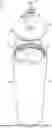
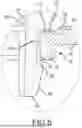
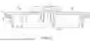
FIG. 1 is a perspective view of an example container assembly in accordance with the principles of the present disclosure.
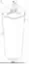
FIG. 2 is an exploded perspective view of the container assembly of FIG. 1.
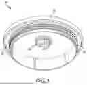
FIG. 3 is a bottom perspective view of an example lid assembly in accordance with the principles of the present disclosure.
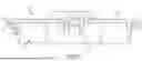
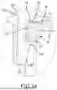
FIG. 4 is a cross-sectional side view of the lid assembly of FIG. 3.
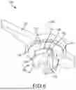
FIG. 5 is a focused cross-sectional side view of the lid assembly of FIG. 3.
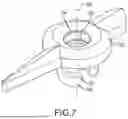
FIG. 6 is a bottom perspective view of an example lid attachment in accordance with the principles of the present disclosure.
FIG. 7 is a top perspective view of the lid attachment of FIG. 6.
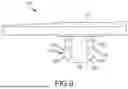
FIG. 8 is a side view of the lid attachment of FIG. 6.
FIG. 9 is a bottom view of the lid attachment of FIG. 6.
FIG. 10 is a top perspective view of another example lid attachment in accordance with the principles of the present disclosure.
FIG. 11 is a bottom perspective view of the lid attachment of FIG. 10.
FIG. 12 is a cross-sectional side view of the lid attachment of FIG. 10.
FIG. 13 is a cross-sectional side view of an alternate embodiment of the lid assembly of FIG. 3.
FIG. 14 is a focused cross-sectional side view of an alternate embodiment of the lid assembly of FIG. 3.
DETAILED DESCRIPTION
Various embodiments will be described in detail with reference to the drawings, wherein like reference numerals represent like parts and assemblies throughout the several views. Reference to various embodiments does not limit the scope of the claims attached hereto. Additionally, any examples set forth in this specification are not intended to be limiting and merely set forth some of the many possible embodiments for the appended claims.
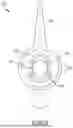
FIG. 1 is a perspective view of an example container assembly 10 that includes a container 20, a straw 38, and a lid assembly 40. The lid assembly 40 includes a lid 50 with a lid attachment 100. Each of these features will be described in detail below.
The container 20 may be an example beverage container. As can be seen in FIG. 2, and in certain examples, the container 20 includes an opening 22 that is circular in shape. In certain examples, the container 20 includes a wall 24 that is tubular in a frustoconical shape extending between an opening end 26 and a base 28. In other examples, the container wall 24 may be cylindrical or another shape. The wall 24 forms an interior space 34.
An example lid assembly 40 is shown in FIGS. 3-5. The lid assembly 40, in preferred examples, is designed to form a close fit with the container 20 at the opening 22. The lid 50 includes a contact edge 56 that is shaped according to the opening 22 shape. In certain examples, the lid 50 includes an outer lip 52 which mounts to the opening end 26 of the wall 24. In certain examples, the lip 52 forms a sealing channel 55. In certain examples, the sealing channel holds a gasket or O-ring 36 that is compressed onto the opening end 26 of the container 20 when the lid assembly 40 is mounted to the container. In certain examples, the lid assembly 40 includes one or more gaskets or O-rings that extend circumferentially around the contact edge 56 and are designed to slidably engage an interior surface 30 of the container 20. In certain examples, the lid 50 includes a threaded portion circumferentially around the contact edge 56 that engages a corresponding threaded region on the interior surface 30 of the container 20. It should be noted that a threaded contact edge 56 is only one of the exemplary methods of attaching and sealing the lid 50 against the container 20 and that other methods are contemplated by the present disclosure.
The lid 50 also includes a passage 54. In certain examples, the passage 54 is centrally located on the lid 50 and provides a through hole between an exterior 51 of the lid 50 and an interior 53 of the lid. The exterior 51 forms a portion of an exterior surface 12 of the container assembly 10. A passage axis 72 is defined centrally through the passage extending from the exterior to the interior of the lid 50. In certain examples, the lid 50 includes a contact feature 58 around a perimeter of the passage 54. In certain examples, the contact feature 58 includes an exterior contact ridge 60 on the exterior side of the lid 50. In certain examples, the contact feature 58 includes an interior contact ridge 62 on the interior side of the lid 50.
In certain examples, the exterior contact ridge 60 forms a curved bump or protrusion that provides a contact surface for a lid attachment 100. The exterior contact ridge 60 provides a circular peak surface around the passage 54 for the lid attachment 100 to rest on, while reducing rotational friction between the lid 50 and the lid attachment 100 by reducing surface area contact between the two surfaces.
In certain examples, the exterior contact ridge 60 is recessed below a first exterior surface 64 with a channel 66 formed between the exterior contact surface 60 and the first exterior surface 64. The channel 66 circumferentially surrounds the contact feature 58 and is radially outward from the contact feature 58 about the passage axis 72.
In certain examples, the interior contact ridge 62 forms a curved bump or protrusion that provides an interference or contact surface for attachment features 150 of the lid attachment 100 in order to prevent the lid attachment 100 from being unintentionally removed from the lid 50. In certain examples, the interior contact ridge includes a ledge 68 surrounding an inner edge of the interior contact ridge 62 and adjacent the passage 54. The ledge 68 provides a step feature to catch the attachment features 150 and prevent accidental removal of the lid attachment 100. The interior contact ridge provides curved transition to the ledge 68 that facilitates deflection of the attachment features 150 for removal of the attachment feature. The interior contact ridge 62 extends downward below and extends from a first interior surface 70 of the lid 50.
In certain examples, the passage 54 extends between the exterior contact ridge 60 and the ledge 68. In certain examples, the passage forms a taper radially inward toward the passage axis 72 as the passage moves from the exterior contact ridge 60 toward the ledge 68. In certain examples, there is no taper. In other examples, there is a minimal taper to facilitate manufacturability.
In certain examples, there is no ledge 68 formed on the interior contact ridge 62. FIGS. 13 and 14 show an alternate embodiment of the lid assembly 40 where there is no additional ledge formed on the interior contact ridge 62. Removal of the ledge 68 provides a smoother removal of the lid attachment 100 from the lid 50. In the example shown on FIGS. 13 and 14, the lid attachment is held in by the interior contact ridge alone, without the additional resistance of a ledge 68.
The lid attachment 100 is designed to be fit onto the lid 50 and provides a spinnable/rotatable feature on the lid assembly 40. As shown in FIGS. 6-9, the lid attachment 100 includes a main body 110 defining, according to one example embodiment, an ornamental feature 130, and one or more attachment features 150 that extend outward from the main body 110 of the lid attachment 100. The main body 110 includes a top side 112 and a bottom side 114 where the top side 112 faces away from the lid 50 and the bottom side 114 faces toward the lid 50 and is adjacent the exterior 51 of the lid 50. A central cavity 104 extends through the main body between the top side 112 and the bottom side 114 along a cavity axis 102. In the assembled state, the cavity axis 102 and the passage axis 72 are aligned. The central cavity 104 is sized for a straw 38 to pass through in order for a user to drink from the contents within the interior space 34 of the container 20. In certain examples, the central cavity is a tubular/cylindrical cavity, shaped similarly to an outer cross-section of a typical straw, like straw 38. In certain examples, the central cavity 104 forms a taper radially inward toward the cavity axis 102 as the central cavity 104 moves from the top side 112 toward the bottom side 114. In certain examples, the taper continues to form an inner surface of the attachment features 150. In certain examples, there is no taper. In other examples, there is a minimal taper to facilitate manufacturability.
In certain examples, the central cavity 104 includes a straw contact ridge 106. The straw contact ridge 106 forms a curved bump or protrusion that projects from and extends around a portion of the central cavity 104 radially around the cavity axis 102. In certain examples, as can be seen in FIG. 4, the cross-sectional profile of the straw contact ridge is semi-circular. The straw contact ridge 106 is designed to be a close fit with an outer circumference of the straw 38, while having sufficient clearance between the straw 38 and the straw contact ridge 106 to enable rotation of the lid attachment 100 without being overly restricted by contact with the straw 38. The straw contact ridge 106 is designed to reduce contact friction between the lid attachment 100 and the straw 38 by reducing surface area contact between the two surfaces.
In certain examples, the bottom side 114 forms a stepped surface with a lid contact surface 116 and an offset surface 118. The lid contact surface is a flat surface extending between the central cavity 104 and the offset surface 118. The lid contact surface 116 contacts the lid 50 at the exterior contact ridge 60. In the assembled state, the transition between the lid contact surface 116 and the offset surface 118 occurs at the channel 66 when measured radially outward from the cavity axis 102. The offset surface 118 is flat and spaced apart or offset from the first exterior surface 64 of the lid 50.
The attachment features 150 extend into the passage 54. In certain examples, the attachment features 150 form fingers or cantilevered arms that are designed to flex radially inward toward the passage axis 72 and the cavity axis 102 during insertion and removal of the lid attachment 150 when the attachment features 150 travel into or out of the passage 54. In certain examples, there are two attachment features 150 that extend along opposite sides of the cavity axis 102.
Each of the attachment features 150 are shaped with an inner surface 152, radially inward relative to the cavity axis 102, that forms an extension of the central cavity 102, with the same curved surface that follows the same curved shape of the outer cross-section of a typical straw, like straw 38. Similarly, any taper present in the central cavity 104 continues with the inner surface 152.
A gap 156 is formed between each of the attachment features 150. The gap 156 enables flexible inward movement of the attachment features during insertion and removal of the lid attachment into and out of the lid.
In certain examples, an outer surface 154, radially outward relative to the cavity axis 102 and inner surface 152, of the attachment features 150 includes a passage surface 158 and a retainment feature 160 positioned on a distal end 162 of each attachment feature 150. The passage surface 158 follows the same curvature as the perimeter of the passage 54. In the assembled state, the passage surface 158 extends between the lid contact surface 116 and the retainment feature 160. In certain examples, the transition between the passage surface 158 and the lid contact surface 116 forms a curved fillet.
In certain examples, the passage surface 158 includes a passage contact ridge 164. The passage contact ridge 164 forms a curved bump or protrusion that projects from and extends around a portion of the passage surface 158 radially around the cavity axis 102. The passage contact ridge 164 is designed to be a close fit with the passage 54, while having sufficient clearance between the passage 54 and the passage contact ridge 164 to enable rotation of the lid attachment 100 without being overly restricted by contact with the passage 54. The passage contact ridge 164 is designed to reduce contact friction between the lid attachment 100 and the passage 54 by reducing surface area contact between the two surfaces.
In certain examples, the retainment feature 160 forms a retention bump 161 that is stepped outward at an angle greater than 90 degrees at the transition between the passage surface 158 and the retainment feature 160. By having an angle greater than 90 degrees, the retention feature 160 is able to slide past the ledge 68 without catching. The retention bump 161 also follows the same radial curvature as the perimeter of the passage 54. The retention bump 161, in its natural uncompressed state, has an apex 163 that is radially outward of the passage 54 such that upward movement of the attached lid attachment 100 causes interference between the ledge 68 and the retainment feature 160.
The retention feature 160 forms a taper 166 from the apex 163 to the distal end 162. The taper 166 facilitates assembly of the lid attachment 100 with the lid 50. The distal end 162 is radially inward of the passage such that the attachment features 150 are able to enter the passage 54 with the taper 166 facilitating further flexible inward movement of the attachment features 150. The attachment features 150 will be maximally compressed when the apex 163 of the retention bump 161 is in the passage 54. As the apex 163 passes into the interior space 34 and passes the passage 54, the attachment features 150 return to their natural, uncompressed state.
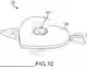
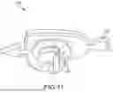
FIGS. 10-12 show another example lid attachment 200. The lid attachment 200 has many similarities to the lid attachment 100, and therefore only certain differences are mentioned. Where the features of the lid attachment 200 are the same as the lid attachment 100, the same numbering is used. For example, the attachment features 150 are the same on the lid attachments 100 and 200.
The ornamental feature 130/230 can be defined by or connected to the top side 112/212 of the main body 110/210. The ornamental feature 130/230 may take many forms. For example, the ornamental feature 130/230 may be a shape, a figurine, a toy, a seasonal object, a holiday object, etc. As seen in FIGS. 6-9, the ornamental feature 130 is an arrow. In other examples, like shown in FIGS. 10-12, the ornamental feature is a heart with an arrow extending through the heart.
The lid attachment 100/200 is designed to spin about the cavity axis 102/passage axis 72 when the lid attachment is assembled to the lid 50. Various features improve the rotatability of the lid attachment 100/200 by reducing the contact surface area between neighboring components like the straw 38 and the lid 50. For instance, as previously described, the straw contact ridge 106, the exterior contact ridge 62, and the passage contact ridge 164 are all designed to minimize contact, and thereby friction, during rotation of the lid attachment 100/200. In certain examples, the first exterior surface 64 may include different regions, like a game board, in order to gamify the spinning of the ornamental feature 130/230. In certain examples, the first exterior surface 64 may include textured art that interfaces with a rotating ornamental feature. In certain examples, the first exterior surface may have a sticker or other coating over the cover. The offset surface 118 provides clearance for art or other aspects on the lid surface.
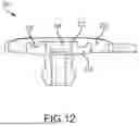
The ornamental feature 130/230 may be defined by or connected to the main body 110/210 in a number of ways. As shown in FIG. 4, the ornamental feature 130 is integrally formed with the other portions of the lid attachment 100. In certain examples, the entire lid attachment may be integrally formed through a process such as injection molding or additive manufacturing. As can be seen in FIG. 12, the ornamental feature 230 may be overmolded to the main body 210. The main body 210 includes an overmold channel 220 that is positioned radially offset from the central cavity 204 on a top side 212 of the lid attachment 200. The overmold channel 220 provides mechanical attachment for the ornamental feature 230. In certain examples, the overmolded ornamental feature 230 extends to and forms an upper portion of the central cavity 204.
In certain examples, the entire lid attachment 100/200 is made from a polymeric material. In certain examples, the lid attachment 100/200 is made from nylon. In certain examples, the main body 110/210 is made from a first polymeric material and the ornamental feature 130/230 is made from a second polymeric material. In certain examples, the first polymeric material is nylon and the second polymeric material is silicone.
The various embodiments described above are provided by way of illustration only and should not be construed to limit the claims attached hereto. Those skilled in the art will readily recognize various modifications and changes that may be made without following the example embodiments and applications illustrated and described herein, and without departing from the full scope of the following claims.
Claims
What is claimed is:1. A lid attachment for a beverage container lid comprising:
a main body including a central cavity extending through the main body about a cavity axis, the central cavity providing access between a top side and a bottom side of the main body, the central cavity being sized to accommodate entry of a straw; and
a plurality of attachment features, the plurality of attachment features extending outward from the bottom side of the main body, the plurality of attachment features each including a distal free end, the distal free end including a retainment feature, the lid attachment, when mounted to a beverage container lid, being rotatable about the cavity axis relative to the beverage container lid.
2. The lid attachment of claim 1, further comprising an ornamental feature connected to the main body.
3. The lid attachment of claim 1, wherein the central cavity includes a straw contact ridge projecting radially inward, wherein the straw contact ridge is configured to minimize contact between the lid attachment and the straw.
4. The lid attachment of claim 1, wherein the bottom side includes a lid contact surface and an offset surface, wherein the lid contact surface is configured to provide limited contact between the bottom side of the lid attachment and the beverage container lid.
5. The lid attachment of claim 1, wherein the plurality of attachment features each include a passage contact ridge on an outer surface of the attachment feature, the passage contact ridge configured to minimize contact between the lid attachment and a passage through the beverage container lid.
6. The lid attachment of claim 2, wherein the ornamental feature is integrally connected to the main body.
7. The lid attachment of claim 2, wherein the main body and the plurality of attachment features are integrally connected, wherein the ornamental feature is overmolded to the main body.
8. The lid attachment of claim 1, wherein the distal free ends of the plurality of attachment features are capable of deflecting radially inward toward the cavity axis.
9. The lid attachment of claim 1, wherein the retainment feature forms a retention bump that is stepped outward from a passage surface on each of the plurality of attachment features.
10. The lid attachment of claim 9, wherein the retention bump includes a taper between an apex and the distal free end.
11. A lid assembly for a beverage container comprising:
a lid defining an exterior side and an interior side, the lid defining a passage extending between the exterior side and the interior side;
a lid attachment comprising:
a main body positioned on the exterior side of the lid, the main body including a central cavity extending through the main body about a cavity axis, the central cavity providing access between a top side and a bottom side of the main body, the central cavity being sized to accommodate entry of a straw; and
a plurality of attachment features connecting the lid attachment to the lid, the plurality of attachment features projecting outward from the bottom side of the main body and through the passage of the lid, the lid attachment being rotatable about the cavity axis independent of the lid.
12. The lid assembly of claim 11, further comprising an ornamental feature connected to the main body and positioned on the exterior side of the lid.
13. The lid assembly of claim 11, wherein a contact feature defines a perimeter of the passage, wherein the contact feature includes an exterior contact ridge on the exterior side and an interior contact ridge on the interior side.
14. The lid assembly of claim 13, wherein the bottom side of the lid includes a lid contact surface and an offset surface, wherein the lid contact surface contacts the exterior contact ridge, wherein the contact between the lid and lid attachment is minimized to reduce friction during rotation of the lid attachment.
15. The lid assembly of claim 13, wherein the exterior contact ridge is below a first exterior surface, wherein the exterior contact ridge and the first exterior surface are separated by a channel.
16. The lid assembly of claim 13, wherein the interior contact ridge contacts retention bumps on the plurality of attachment features during removal of the lid attachment from the lid.
17. The lid assembly of claim 16, wherein the interior contact ridge includes a ledge, wherein the ledge prevents unintentional removal of the lid attachment from the lid.
18. The lid assembly of claim 16, wherein the retention bumps include a taper between an apex and a distal free end of each of the plurality of attachment features, wherein the taper facilitates insertion of the attachment features through the passage.
19. The lid assembly of claim 11, wherein the plurality of attachment features each include a passage contact ridge on an outer surface of the attachment feature, wherein the passage contact ridge contacts the passage, wherein the contact between the lid and lid attachment is minimized to reduce friction during rotation of the lid attachment.
20. The lid assembly of claim 11, wherein the central cavity includes a straw contact ridge along a perimeter of the central cavity, wherein the straw contact ridge is designed to contact a straw, wherein the contact between the lid attachment and the straw is minimized to reduce friction during rotation of the lid attachment.
21. A beverage container assembly comprising:
a container;
a lid defining an exterior side and an interior side, the lid defining a passage extending between the exterior side and the interior side, and a contact feature defining a perimeter of the passage;
a lid attachment comprising:
a main body defining a top side and a bottom side, the main body including a central cavity extending through the main body about a cavity axis, at least a portion of the bottom side of the main body contacting the contact feature of the lid;
a plurality of attachment features, the plurality of attachment features extending outward from the main body and extending through the passage, the plurality of attachment features connecting the lid attachment to the lid, wherein the lid attachment is rotatable about the cavity axis independent of the lid; and
a straw extending through the central cavity.
22. The beverage container assembly of claim 21, further comprising an ornamental feature connected to the main body on the top side.
23. The beverage container assembly of claim 21, wherein the central cavity includes a straw contact ridge along a perimeter of the central cavity, wherein the straw contact ridge is designed to contact the straw, wherein the contact between the lid attachment and the straw is minimized to reduce friction during rotation of the lid attachment.
Images & Drawings included:

Sources:
- United States Patent and Trademark Office - verify current appl. status at the USPTO↗
Recent applications in this class:
- » 20250368408 2025-12-04
LID FOR A CONTAINER FOR FOOD OR BEVERAGE - » 20250368407 2025-12-04
BRAKE FLUID RESERVOIR CAP - » 20250340346 2025-11-06
DateTrack Food Storage Box - » 20250270010 2025-08-28
WATER BOTTLE WITH CONSUMPTION TRACKING AND PH SENSING CAP - » 20250242983 2025-07-31
Bottle cap - » 20250136336 2025-05-01
Mason Jar Lid - » 20250083878 2025-03-13
INTERACTIVE CAN - » 20250074670 2025-03-06
Customizable Food Service Containers with Trackable and E-commerce Functionality - » 20240327083 2024-10-03
POSITIONAL INDICATOR HAVING A BITMAPPED PATTERN - » 20240317470 2024-09-26
SOLVENT TUBE MANAGEMENT
Recent applications for this Assignee:
- » 20240051715 2024-02-15
Splash-resistant lid for beverage container - » 20230146792 2023-05-11
Double-walled beverage container and method of forming the same - » 20220280961 2022-09-08
Airpot beverage dispenser - » 20220250828 2022-08-11
Double-walled beverage container and method of forming the same - » 20220009680 2022-01-13
Cam lid for drinking vessel - » 20210331839 2021-10-28
Beverage container closure with venting - » 20210039872 2021-02-11
Double-walled beverage container and method of using same - » 20200369444 2020-11-26
Drink container and leak proof plug lid for use therewith - » 20200367677 2020-11-26
Drink container and leak proof plug lid for use therewith - » 20200352371 2020-11-12
Lockable beverage container closure