SYSTEM AND METHOD FOR OPERATING THEATER CABLE RETRACTOR
US20260145907A1
2026-05-28
19/178,417
2025-04-14
Smart Summary: A cable retractor is designed to hold and release cables easily. It has a reel inside a shell, allowing the cable to move through a central opening. The reel can spin in one direction multiple times, thanks to a spring that helps it wind. A ratchet and a pawl work together to keep the reel in place until an external trigger is pulled. When the trigger is activated, the pawl releases, letting the spring unwind the reel in the opposite direction. 🚀 TL;DR
Abstract:
Provided is a cable retractor having a reel disposed within a shell having a bottom and peripheral sidewall. A central opening is disposed axially through the reel and shell, the reel and structured and arranged to provide a generally open pathway from a first vertical slot in the peripheral sidewall, through an open channel across a portion of the reel from a peripheral edge of a top radial wall of the reel to the central opening and from the central opening through a recessed groove in the bottom of the shell from the central opening through the peripheral sidewall. finger grips are provided by the reel to either side of the central opening. A ratchet is coupled to the bottom radial wall of the reel. A spring disposed between the reel and the generally round shell, the spring structured and arranged to permit the reel to be wound in a first direction for a plurality of complete revolutions. A pawl is disposed between the shell and the reel and structured and arranged to temporarily engage the ratchet. An external trigger is structured and arranged to disengage the pawl from the ratchet and allow the spring to drive rotation of the reel in a second direction opposite to the first. A method of use is also provided.
Assignee:
- LLC, LLC 3 🇺🇸 Centennial, CO, United States
Applicant:
Interested in similar patents?
Get notified when new applications in this technology area are published.
Classification:
B65H75/4492 » CPC main
Storing webs, tapes, or filamentary material, e.g. on reels; Cores, formers, supports, or holders for coiled, wound, or folded material, e.g. reels, spindles, bobbins, cop tubes, cans, mandrels or chucks specially adapted or mounted for storing and repeatedly paying-out and re-storing lengths of material provided for particular purposes, e.g. anchored hoses, power cables involving the use of a core or former internal to, and supporting, a stored package of material; Constructional details; Arrangements or adaptations for driving the reel or the material Manual drives
B65H75/4471 » CPC further
Storing webs, tapes, or filamentary material, e.g. on reels; Cores, formers, supports, or holders for coiled, wound, or folded material, e.g. reels, spindles, bobbins, cop tubes, cans, mandrels or chucks specially adapted or mounted for storing and repeatedly paying-out and re-storing lengths of material provided for particular purposes, e.g. anchored hoses, power cables involving the use of a core or former internal to, and supporting, a stored package of material; Constructional details; Arrangements of the frame or housing Housing enclosing the reel
B65H75/486 » CPC further
Storing webs, tapes, or filamentary material, e.g. on reels; Cores, formers, supports, or holders for coiled, wound, or folded material, e.g. reels, spindles, bobbins, cop tubes, cans, mandrels or chucks specially adapted or mounted for storing and repeatedly paying-out and re-storing lengths of material provided for particular purposes, e.g. anchored hoses, power cables involving the use of a core or former internal to, and supporting, a stored package of material; Constructional details; Automatic re-storing devices Arrangements or adaptations of the spring motor
B65H2701/34 » CPC further
Handled material; Storage means; Handled filamentary material electric cords or electric power cables
B65H75/44 IPC
Storing webs, tapes, or filamentary material, e.g. on reels; Cores, formers, supports, or holders for coiled, wound, or folded material, e.g. reels, spindles, bobbins, cop tubes, cans, mandrels or chucks specially adapted or mounted for storing and repeatedly paying-out and re-storing lengths of material provided for particular purposes, e.g. anchored hoses, power cables involving the use of a core or former internal to, and supporting, a stored package of material Constructional details
B65H75/48 IPC
Storing webs, tapes, or filamentary material, e.g. on reels; Cores, formers, supports, or holders for coiled, wound, or folded material, e.g. reels, spindles, bobbins, cop tubes, cans, mandrels or chucks specially adapted or mounted for storing and repeatedly paying-out and re-storing lengths of material provided for particular purposes, e.g. anchored hoses, power cables involving the use of a core or former internal to, and supporting, a stored package of material; Constructional details Automatic re-storing devices
Description
CROSS REFERENCE TO RELATED APPLICATIONS
This application claims the benefit under 34 U.S.C. § 119(e) of U.S. Provisional Application No. 63/658,091filed Jun. 10, 2024, and entitled SYSTEM AND METHOD FOR OPERATING THEATER CABLE RETRACTOR, the disclosure of which is incorporated herein by reference.
FIELD OF THE INVENTION
The present invention relates generally to surgical operating theater equipment, and more specifically to an adaptable and adjustable standing platform for a surgeon.
BACKGROUND
Within the surgical environment of an operating theater there are essentially two environments. The first is the sterile environment which is typically about the patient, or at least the operating site arround the patient, and the second is the non-sterile environment, such as the floor, where blood, tissue, fluids, shoes and other items may fall during the surgery.
Because of the invasive nature of surgery into a patient's body, maintaining the sterile environment is important for patient care and wellbeing. This can be, and often is, challenging as elements within the operating theater environment may inadvertently transition between the sterile and non-sterile environments, or even bridge between them.
In the most contemporary surgeries, several surgical tools are utilized within the sterile environment, such as cautery devices and drills, have cables which are connected to a base or power source that is on the floor or otherwise outside of the sterile environment. The non-sterile end of the cable remains plugged in to a base or power source, and the cable then continues up and into the sterile environment where it is used during the surgery.
But for freedom of movement of the tool, the cable must be of a sufficient length to permit the surgeon to use it and move it freely. As such, this cable may be pulled up, or dropped down, and in so doing may pass in and out of the sterile environment.
In addition, there may be multiple different tools—a cautery device, a drill, a camera and lighting device, etc. . . . each with its own cable. During use and switching from one tool to another, the cables may become entangled. As a result, when one tool is put down and another picked up, the entangling of the cables may inadvertently cause movement of the new tool to pull on another tool—dislodging it and causing it to fall out of the sterile environment and onto the floor.
In such an event, a new replacement tool must be obtained, leading to possible delay in the surgery as well as the additional cost of multiple tools being necessarily on hand as ready backups. Further still, technicians in the operating theater may frequently have to untangle cables and strive to keep them tucked up and within the sterile environment—further detracting them from their primary focus of assisting with the operation and care of the patient.
Current cable management systems typically require the user to manually wind and unwind the cables about some frame or spool. These frames also offer no barrier or other means of physical separation between the attachment end (the end that is intended to be in the non-sterile environment) and the operator end (the end that is intended for use within the sterile environment).
Keeping the cable wound about the frame or spool, also requires some sort of retainer—an elastic band or strap, or passing the cable itself in some under/over pattern to achieve a binding of the cable upon the frame or spool. Such methods of securing require additional time to both release and rebind which once again may delay the surgeon.
Moreover, current options for cable management devices do not safely and reliably distinguish between the attachment end and the operation end, easily and quickly take in or pay out the managed cable, avoid entanglement, and otherwise help avoid the common mishaps due to cable entanglement and contamination.
Hence there is a need for a method and system that is capable of overcoming one or more of the above identified challenges.
SUMMARY OF THE INVENTION
Our invention solves the problems of the prior art by providing novel systems and methods for a cable retractor, suitable for use in an operating theater.
In particular, and by way of example only, according to at least one embodiment, provided is an operating theater cable retractor, including: a reel disposed within a shell having a bottom and peripheral sidewall, a central opening disposed axially through the reel and shell, the reel and shell structured and arranged to provide a generally open pathway from a first vertical slot in the peripheral sidewall, through an open channel across a portion of the reel from a peripheral edge of a top radial wall of the reel to the central opening and from the central opening through a recessed groove in the bottom of the shell from the central opening through the peripheral sidewall; finger grips provided by the reel to either side of the central opening; a ratchet coupled to the bottom radial wall of the reel; a spring disposed between the reel and the generally round shell, the spring structured and arranged to permit the reel to be wound in a first direction for a plurality of complete revolutions; a pawl structured and arranged between the shell and the reel to temporarily engage the ratchet; and an external trigger structured and arranged to disengage the pawl from the ratchet and allow the spring to drive rotation of the reel in a second direction opposite to the first.
For yet another embodiment, provided is an operating theater cable retractor, including: a generally round shell including a bottom and peripheral sidewall rising generally normally from the bottom, the shell having a first central aperture in the bottom and a recessed groove disposed in an outside surface of the bottom between the first central aperture and the sidewall, the sidewall having a distal lip above the bottom and a vertical slot in the peripheral sidewall extending from the distal lip partway towards the bottom; a reel disposed within the round shell, the reel including: a top radial wall and a bottom radial wall defining a cable receiving space about the reel, each radial wall having an outer periphery edge; a second central aperture aligned above the first central aperture; finger grips disposed to either side of the second central aperture; an open channel disposed through the top radial wall between the second central aperture and the outer periphery edge of the top radial wall, the reel rotatable to align the open channel with the first vertical slot in the round shell; a ratchet coupled to the bottom radial wall of the reel; a spring disposed between the reel and the generally round shell, the spring structured and arranged to permit the reel to be wound in a first direction for a plurality of complete revolutions; a pawl structured and arranged between the generally round shell and the reel to temporarily engage the ratchet; and an external trigger structured and arranged to disengage the pawl from the ratchet and allow the spring to drive rotation of the reel in a second direction opposite to the first; wherein an operator grasping the finger grips may rotate the reel a plurality of times in the first direction and align the open channel of the reel to the first vertical slot of the round shell, a cable then disposed through the first vertical slot, through the open channel through the aligned first and second central apertures, and through the recessed groove, an excess of cable remaining outside of the first vertical slot, operation of the external trigger releasing the pawl such that the spring drives the reel in the second direction retracting the excess of cable about the reel.
Still for yet another embodiment, provided is a method of organizing cables in an operating theater with an operating theater cable retractor, including: receiving an operating theater cable retractor including: a reel having a top radial wall and a bottom radial wall defining a cable receiving space about the reel disposed within a shell having a bottom and peripheral sidewall, a central opening disposed axially through the reel and shell, the reel and shell structured and arranged to provide a generally open pathway from a first vertical slot in the peripheral sidewall, through an open channel across a portion of the reel from a peripheral edge of the a top radial wall of the reel to the central opening and from the central opening through a recessed groove in the bottom of the shell from the central opening through the peripheral sidewall; finger grips provided by the reel to either side of the central opening; a ratchet coupled to the bottom radial wall of the reel; a spring disposed between the reel and the generally round shell, the spring structured and arranged to permit the reel to be wound in a first direction for a plurality of complete revolutions; a pawl structured and arranged between the shell and the reel to temporarily engage the ratchet; and an external trigger structured and arranged to disengage the pawl from the ratchet and allow the spring to drive rotation of the reel in a second direction opposite to the first; in a first instance with the reel at rest, using the finger grips to rotate the reel in a first direction a plurality of complete revolutions to align the open pathway to the first vertical slot; disposing a cable through the first vertical slot, through the open channel through the aligned first and second central apertures, and through the recessed groove, an excess of cable remaining outside of the first vertical slot; operating the external trigger releasing the pawl such that the spring drives the reel in the second direction retracting in the excess of cable about the reel.
BRIEF DESCRIPTION OF THE DRAWINGS
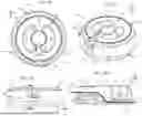
FIGS. 1A-1D provide corresponding top perspective, top, side and cut through views of an assembled cable retractor in accordance with at least one embodiment of the present invention;
FIG. 2 is an exploded side view of the elements of a cable retractor in accordance with at least one embodiment of the present invention;
FIGS. 3A-3D provide corresponding top perspective, top, side and cut through views of the shell 104 of a cable retractor in accordance with at least one embodiment of the present invention;
FIGS. 4A-4D provide corresponding top perspective, top, side and cut through views of the reel 102 of a cable retractor in accordance with at least one embodiment of the present invention;
FIGS. 5A-5D provide corresponding top perspective, top, side and end views of the reel of a cable retractor in accordance with at least one embodiment of the present invention;
FIGS. 6A-6D provide corresponding top perspective, top, side and end views of the bottom of a cable retractor in accordance with at least one embodiment of the present invention;
FIGS. 7A-7C provide corresponding top, side and end views of the pawl of a cable retractor in accordance with at least one embodiment of the present invention;
FIGS. 8A-8D provide corresponding top perspective, top, side and end views of the trigger of a cable retractor in accordance with at least one embodiment of the present invention;
FIG. 9 provides an exploded perspective view of the elements of a cable retractor in accordance with at least one embodiment of the present invention;
FIGS. 10A and 10B are photographs of an embodiment of a cable retractor loaded with a surgical tool cable in accordance with at least one embodiment of the present invention; and
FIG. 11 is a flow diagram of a method of organizing cables in an operating theater with an operating theater cable retractor in accordance with at least one embodiment of the present invention.
DETAILED DESCRIPTION
Before proceeding with the detailed description, it is to be appreciated that the present teaching is by way of example only, not by limitation. The concepts herein are not limited to use or application with a specific system or method for cable retraction in or outside of an operating theater. Thus, although the instrumentalities described herein are for the convenience of explanation shown and described with respect to exemplary embodiments, it will be understood and appreciated that the principles herein may be applied equally in other types of systems and methods involving cable retraction.
This invention is described with respect to preferred embodiments in the following description with references to the Figures, in which like numbers represent the same or similar elements. It will be appreciated that the leading values identify the Figure in which the element is first identified and described, e.g., element 100 first appears in FIG. 1.
To briefly summarize, provided is a system and method for cable organization, and more specifically to cable organization within a medical or surgical operating theater—hereinafter “operating theater”. The system and method advantageously allow a cable powering a surgical tool to be coiled unidirectionally at any length along the cable. In this way, a portion of cable attached to the sterile operative tool can repeatedly be uncoiled for use and then coiled on the reel for storage when not in use. The length of cable that plugs into the base power unit remains static. The system is also universal, and can be adapted for use with any cable diameter or manufacturer. Moreover, the system and method for the disclosed cable retractor advantageously reduce the opportunity for cables to become entangled, and/or for attached surgical tools to be accidentally knocked to the floor.
Turning now to the figures, and initially FIGS. 1A-1D , for at least one embodiment, the cable retractor 100 is provided by a reel 102 disposed within a shell 104 having a bottom 106 and a peripheral sidewall 108, with a central opening disposed axially through the reel 102 and shell 104. It is to be understood that the terms of element identification as used herein—such as reel 102 and shell 104, are terms of convenience. The reel 102 may also be identified as a spool 102, and the shell 104 may be identified as a base without departing from the scope of the inventive concept herein described.
To facilitate the description of systems and methods for embodiments of cable retractor 100, the orientation of cable retractor 100 and various elements as presented in the figures is referenced to the coordinate system with three axes orthogonal to one another as shown in FIG. 1A. The axes intersect mutually at the origin of the coordinate system, which is chosen to be the center of cable retractor 100, however the axes shown in all figures are offset from their actual locations for clarity and ease of illustration.
More specifically FIG. 1A provides an upper perspective view of at least one embodiment of the cable retractor 100, with FIG. 1B providing a top view, FIG. 1C a side view and FIG. 1D a cut through side view.
With respect to these figures, it may be further appreciated that, in accordance with at least one embodiment, the reel 102 and spool 102 are structured and arranged to provide a generally open pathway 112 from a first vertical slot 114 in the peripheral sidewall 108 through an open channel 116 across a portion of the reel 102 from a peripheral edge of a top radial wall 118 of the reel 102 to the central opening 110, and from the central opening 110 through a recessed groove 120 in the bottom 106 of the shell 104. Indeed, the cut through view of FIG. 1D has been augmented with a portion of a cable 122 disposed in this described path.
As will be further described below, the portion of the cable running to the base is maintained as a static length, and the portion of the cable running to the surgical tool is the cable portion that may be retracted into the cable retractor 100 and fed back out from the cable retractor 100. Indeed, wherever the cable retractor 100 is positioned along a cable, one end of the cable will remain static in length, and the other will be dynamic in length—retracted into and dispensed from the cable retractor 100.
With respect to FIGS. 1A and 1B, it may also be appreciated that for at least one embodiment, the cable retractor 100 provides finger grips 124 disposed in the reel 102 to either side of the central opening 110. For at least one alternative embodiment, the finger grips 124 may be a knob or handle that extends upward from the reel 102.
As the name suggests, these finger grips 124 permit a user to dispose his or her finger tips within the reel 102 and wind it in a first direction to load a spring 200 disposed between the reel 102 and the generally round shell 104 (see FIG. 2). It will be appreciated that the spring 200 is structured and arranged to permit the reel 102 to be wound in a first direction for a plurality of complete revolutions.
With respect to exploded side plane view in FIG. 2, it may also be appreciated that a ratchet 204 is coupled to the bottom radial wall 202 of the reel 102 and a pawl 206 is structured and arranged to be disposed between the shell 104 and the reel 102 to temporarily engage the ratchet 204. For at least one embodiment as shown in FIGS. 1A, 1B and 1C, a trigger 126 extends from the peripheral sidewall 108, and when activated—such as by being depressed—the trigger 126 releases the pawl 206. If a user has previously used the finger grips 124 to rotate the reel 102 in a first direction, and thereby loaded the spring 200, the release of the pawl 206 releases the ratchet 204 which thus permits the reel 102 to rotate in a second direction opposite to the first.
In FIG. 2, a retainer clip 208 may also be appreciated, the retainer clip 208 engaging with the ratchet 204 when it is engaged with the spring 200 and disposed through the shell 104 so as to assemble the elements together.
The advantageous nature of the cable retractor 100 may be more fully appreciated with an overview of its use. For at least one embodiment, the cable retractor 100 may be retrieved pre-surgery, from a package, such as a hermetically sealed and sterilized package. The cable retractor 100 may have been liberated from its packaging at some prior event and maintained in a sterile storage, or subjected to a sterilization process prior to being delivered to or otherwise disposed in, the operating theater.
A user will pick up and pre-load the spring of the cable retractor 100 by turning the reel with the finger grips 124 several times with the last rotation aligning the open pathway 112 of the reel 102 with the first vertical slot 114 of the shell 104 peripheral sidewall 108. For at least one embodiment, the number of complete turns of the reel 102 is between 3 and 6. In addition, for at least one embodiment, the cable retractor 100 may be assembled and the reel 102 pre-wound, before packaging, sterilizing and shipping.
The user will then pass a device cable through the central opening 110. Whether it is the base connection end or the tool connection end may be a matter of user preference as well as connector size, for it is understood and appreciated that the cable retractor 100 has been structured and arranged with a central opening 110 of sufficient size to accommodate either or both of the connectors.
A sufficient amount of the cable should be disposed through the central opening 110 and recessed groove 120 in the bottom 106, for this end is the base connection end and will not be involved in the retraction and release of the remaining portion of the cable passing through the open pathway 112 and on to the tool. Indeed, the base connection end will very likely be outside of the intended sterile environment, especially if the base is disposed on or in the floor. However, as the cable retractor 100 essentially divides the cable into a base connection portion and the tool connection portion, the tool connection end is safely and securely retracted onto and dispensed from the reel 102, which is physically isolated from the base connection portion of the cable. As such the tool connection portion of the cable is advantageously maintained in a sterile state.
With the base connection end appropriately positioned and the remaining tool connection end run through the open pathway 112, the user depresses the trigger 126, releasing the pawl 206 which in turn releases the ratchet 204 and allows the loaded spring 200 to drive the reel 102 in the second direction. As the reel 102 rotates in the second direction, it retracts the tool connection end of the cable into the cable retractor 100 as it is wound about the reel 102.
It will be understood and appreciated that the length of cable that may be wound about the reel 102 is dependent upon the size of the reel 102 and the number of revolutions permitted by the spring 200. For at least one embodiment, the reel 102 is about 3″ to 4″ inches in diameter and the spring permits between 3 and 6 revolutions, such that the cable retractor 100 is advantageously structured and arranged to retract in between 18″ and 30″ of cable.
With the cable safely contained within the cable retractor 100, the cable retractor 100 itself can be positioned within the sterile environment, such as by hook and loop fuzzy attachers (e.g., Velcro®, removable adhesive, elastic straps, disposed in a cable retractor 100 receiving pocket, or other desired location.
For at least one embodiment, when use of the tool to which the tool connection end of the cable is desired, the user can simply pull upon the tool connection end of the cable. Doing so will extract the cable from about the reel 102, and in so doing rotate the reel 102 in the first direction—thus re-loading the spring 200. The pawl 206 and ratchet 204 ensure that the incremental extraction of the cable does not place the cable under constant tension.
When use of the tool is no longer desired, a user need only depress the trigger for the cable retractor 100 to retract the extended portion of the tool connection portion of the cable.
Returning to the exploded view of FIG. 2, the nature of the reel 102, ratchet 204, spring 200, shell 104, trigger 126, retainer clip 208, pawl 206, and bottom 106 may further appreciated with respect to FIGS. 3A-8D.
FIG. 3A presents a perspective top view of the shell 104, further permitting appreciation of the peripheral sidewall 108 and the first vertical slot 114. The central opening 110 through the cable retractor 100 is provided at least in part by a central aperture (the first central aperture 300) through the shell 104. FIGS. 3B, 3C and 3D provide corresponding top, side and side cut through views of the shell 104. In FIG. 3D, a first spring anchor point 302 may be appreciated as well.
For at least one embodiment, the shell 104 is generally round, however, it will be understood and appreciated that the outer geometry of the shell 104 may be as a square, hexagon or other geometric shape as may be desired, such as for visual distinction between multiple cable retractor 100s.
FIG. 4A presents a perspective top view of the reel 102, further permitting appreciation of the top radial wall 118 and the bottom radial wall 202, each having an outer periphery edge 400—the top radial wall 118 having outer periphery edge 400A, the bottom radial wall 202 having outer periphery edge 400B, and defining a cable receiving space 402 therebetween. This cable receiving space 402 may be further defined by an inset wall 404 disposed between the top radial wall 118 and the bottom radial wall 202.
The central opening 110 through the cable retractor 100 is provided at least in part by a central aperture (the second central aperture 406) through the reel 102. It may also be appreciated that an open channel 116 is disposed through the top radial wall 118 between the outer periphery edge 400A of the top radial wall 118 and the central aperture (the second central aperture 406). FIGS. 4B, 4C and 4D provide corresponding top, side and side cut through views of the reel 102.
In addition, for at least one embodiment, the bottom of the reel 102 provides a plurality of holes 408 through which snap attachers provided by the ratchet 204 may be disposed so as to affix the reel 102 to the ratchet 204. For at least one embodiment as shown, the holes 408 are disposed within the recesses provided as finger grips 114.
FIG. 5A presents a top perspective view of the ratchet 204, which may also be referred to as a ratchet gear 204. As with the shell 104 and reel 102, the central opening 110 through the cable retractor 100 is provided at least in part by a central aperture (the third central aperture 500) through the ratchet 204. For at least one embodiment, the ratchet 204 provides snap attachers 502 which as noted above serve to attach the reel 102 to the ratchet 204. For at least one embodiment, the snap attachers 502 permit easy removal of the reel 102 from the shell 104 as may be desired for cleaning and re-sterilization of the cable retractor 100.
FIGS. 5B, 5C and 5D provide corresponding top and side views of the ratchet 204. In the side views of FIGS. 5C and 5D, a second spring anchor point 504 is shown, as is a collar 506 that is structured and arranged to pass through the first aperture 300 of the shell 104 (See FIG. 3). A retainer clip groove 508 is also shown, which when a retainer clip 208 (see FIG. 2) is disposed in the groove 508 serves to affix the ratchet 204 to the shell 104 with the spring 200 therebetween and attached to the first and second spring 200 anchor points.
Although for the embodiment as shown in the accompanying figures, the ratchet 204 and reel 102 are shown as separate and distinct structures, for at least one alternative embodiment, the ratchet 204 and reel 102 may be fabricated as a unitary structure. For such an embodiment, the ratchet 204 may be provided as the outer periphery edge of the bottom radial wall 202 of the reel 102.
FIG. 6A presents a top perspective view of the bottom 106. As with the shell 104, reel 102 and ratchet 204, the central opening 110 through the cable retractor 100 is provided at least in part by a central aperture (the fourth central aperture 600) through the bottom 106. FIGS. 6B, 6C and 6D provided corresponding top, side and cut through views of the bottom 106.
The recessed groove 120 disposed between the peripheral sidewall 108 and the fourth central aperture 600/central opening 110 that receives the base connection end of the cable may also be more fully appreciated. For at least one embodiment, the recessed groove 120 is partially covered with at least one cover strip 602 of material, such that the cable may be at least partially covered after it is disposed into the recessed groove 120. This covering with one or more cover strip 602 of material may also help retain the cable within the recessed groove 120. Attachers 604, such as snap clips, are also shown which serve to affix the bottom 106 to the shell 104 are also shown.
FIGS. 7A, 7B and 7C provide corresponding top, side and end views of an embodiment of the pawl 206. For at least one embodiment, the pawl 206 is provided by a compliant material, such as but not limited to plastic, and has a fulcrum point 700. When the activation end 702 is depressed inward, a portion of the pawl 206 pivots about the fulcrum point 700 such that the catch 704 is disengaged from the ratchet 204. When the activation end 702 is released, the catch 704 returns to its initial point and re-engages the ratchet 204.
FIGS. 8A, 8B, 8C and 8D provide corresponding perspective, top side and end views of the trigger in accordance with at least one embodiment. As is appreciated in FIGS. 1A, 1B and 1C, for at least one embodiment the trigger 126 is disposed in the peripheral sidewall 108 of the shell 104. A flange 800 ensures that the trigger 126 remains properly seated between the activation end 702 of the pawl 206 and the shell 104 (not shown in FIGS. 8A-8D).
As a visual summary, FIG. 9 provides an exploded perspective view of the elements comprising the cable retractor 100-reel 102, ratchet 204, spring 200, shell 104, trigger 126, retainer clip 208, pawl 206, and bottom 106. Indeed, the alignment of the first central aperture 300 of the shell 104, the second central aperture 406 of the reel 102, the third central aperture 500 of the rachet, and the fourth central aperture 600 of the bottom collectively providing the central opening 110 may also be more fully appreciated.
FIG. 10A presents a top view of an embodiment of a cable retractor 100 loaded with a cable 122/1000 for a surgical tool. FIG. 10B presents a bottom view of the cable retractor 100 from FIG. 10A, further permitting appreciation of the recessed groove 120 in the bottom 106, and the path of cable 122/1000. In addition, cover strips 602 as briefly described above are shown disposed partially over the recessed groove 120, and serve to help secure the cable 122/1000 within the recessed groove 120. For at least one embodiment, the cable retractor 100 may also include an optional hinged or snap-on cover (not shown) that is structured and arranged to cover the reel 102.
Having described embodiments of the cable retractor 100, and to consolidate the description of use provided above, an embodiment relating to at least one method of organizing cables in an operating theater with an operating theater cable retractor 100 will now be discussed. It will be appreciated that the described method need not be performed in the order in which they are herein described, but that these descriptions are merely exemplary of a method of organizing cables in an operating theater with an operating theater cable retractor 100.
Turning to FIG. 11, presented is a flow diagram for at least one method 1100 of organizing cables in an operating theater with an operating theater cable retractor 100. In general, method 1100 commences with providing/receiving a cable retractor 100 as described above, block 1102.
Utilizing the finger grips, an operator rotates the reel 102 in a first direction to load the spring, block 1104. The cable 122/1000 is then disposed through the first vertical slot 114, through the open channel 116, through the central opening 110 and through the recessed groove 120, block 1106. It will be understood and appreciated that this described order may be reversed without departure from the teachings herein.
With the cable 122/1000 now disposed thorough the cable retractor, the operator simply activates the trigger 126 to release the reel 102, causing it to rotate in a second direction opposite to the first direction, and retract the cable through the first vertical slot 114, block 1108. When use of the cable 122/1000 is desired, pulling the cable 122/1000 back out through the first vertical slot 114 will cause the reel 104 to rotate in the first direction again, re-tensioning the spring such that when the trigger 126 is activated again, the cable 122/1000 will once again be retracted into the cable retractor 100.
Moreover, for at least one embodiment the cable retractor 100 may be summarized as a reel 102 disposed within a shell 104 having a bottom 106 and peripheral sidewall 108. A central opening 110 is disposed axially through the reel 102 and shell 104, the reel 102 and shell 104 structured and arranged to provide a generally open pathway 112 from a first vertical slot 114 in the peripheral sidewall 108, through an open channel 116 across a portion of the reel 102 from a peripheral edge of a top radial wall 118 of the reel 102 to the central opening 110 and from the central opening 110 through a recessed groove 120 in the bottom 106 of the shell 104 from the central opening 110 through the peripheral sidewall 108. finger grips 124 are provided by the reel 102 to either side of the central opening 110. A ratchet 204 is coupled to the bottom radial wall 202 of the reel 102. A spring 200 disposed between the reel 102 and the generally round shell 104, the spring 200 structured and arranged to permit the reel 102 to be wound in a first direction for a plurality of complete revolutions. A pawl 206 is disposed between the shell 104 and the reel 102 and structured and arranged to temporarily engage the ratchet 204. An external trigger 126 is structured and arranged to disengage the pawl 206 from the ratchet 204 and allow the spring 200 to drive rotation of the reel 102 in a second direction opposite to the first.
For yet another embodiment, the cable retractor 100 may be summarized as an operating theater cable retractor 100, including: a generally round shell 104 including a bottom 106 and peripheral sidewall 108 rising generally normally to the bottom 106. The shell 104 has a first central aperture 300 in the bottom 106 and a recessed groove 120 disposed in an outside surface of the bottom 106 between the first central aperture 300 and the sidewall 108, the sidewall 108 having a distal lip above the bottom 106 and a vertical slot in the peripheral sidewall 108 extending from the distal lip partway towards the bottom 106. A reel 102 is disposed within the round shell 104. The reel 102 has a top radial wall 118 and a bottom radial wall 202 defining a cable receiving space 402 about the reel 102, each radial wall having an outer periphery edge 400. The reel also has a second central aperture 406 aligned above the first central aperture 300. The reel also provides finger grips 124 disposed to either side of the second central aperture 406. An open channel 116 is disposed through the top radial wall 118 between the second central aperture 406 and the outer periphery edge 400A of the top radial wall 118, the reel 102 rotatable to align the open channel 116 with the first vertical slot 114 in the round shell 104. A ratchet 204 is coupled to the bottom radial wall 202 of the reel 102. A spring 200 is disposed between the reel 102 and the generally round shell 104, the spring 200 structured and arranged to permit the reel 102 to be wound in a first direction for a plurality of complete revolutions. A pawl 206 is structured and arranged between the generally round shell 104 and the reel 102 to temporarily engage the ratchet 204. An external trigger 126 is structured and arranged to disengage the pawl 206 from the ratchet 204 and allow the spring 200 to drive rotation of the reel 102 in a second direction opposite to the first. The cable retractor is operated by an operator grasping the finger grips 124 to rotate the reel 102 a plurality of times in the first direction and align the open channel 116 of the reel 102 to the first vertical slot 114 of the round shell 104. A cable is then disposed through the first vertical slot 114, through the open channel 116 through the aligned first and second central apertures, and through the recessed groove 120, an excess of cable remaining outside of the first vertical slot 114. Operation of the external trigger 126 releases the pawl 206 such that the spring 200 drives the reel 102 in the second direction retracting the excess of cable about the reel 102.
Changes may be made in the above methods, systems and structures without departing from the scope hereof. It should thus be noted that the matter contained in the above description and/or shown in the accompanying drawings should be interpreted as illustrative and not in a limiting sense. Indeed, many other embodiments are feasible and possible, as will be evident to one of ordinary skill in the art. The claims that follow are not limited by or to the embodiments discussed herein, but are limited solely by their terms and the Doctrine of Equivalents.
Claims
What is claimed:1. An operating theater cable retractor, comprising:
a reel disposed within a shell having a bottom and peripheral sidewall, a central opening disposed axially through the reel and shell, the reel and shell structured and arranged to provide a generally open pathway from a first vertical slot in the peripheral sidewall, through an open channel across a portion of the reel from a peripheral edge of a top radial wall of the reel to the central opening and from the central opening through a recessed groove in the bottom of the shell from the central opening through the peripheral sidewall;
finger grips provided by the reel to either side of the central opening;
a ratchet coupled to the bottom radial wall of the reel;
a spring disposed between the reel and the generally round shell, the spring structured and arranged to permit the reel to be wound in a first direction for a plurality of complete revolutions;
a pawl structured and arranged between the shell and the reel to temporarily engage the ratchet; and
an external trigger structured and arranged to disengage the pawl from the ratchet and allow the spring to drive rotation of the reel in a second direction opposite to the first.
2. The operating theater cable retractor of claim 1, wherein an operator grasping the finger grips may rotate the reel a plurality of times in the first direction and align the open channel of the reel to the first vertical slot of the round shell, a cable then disposed through the first vertical slot, through the open channel through the aligned first and second central apertures, and through the recessed groove, an excess of cable remaining outside of the first vertical slot, operation of the external trigger releasing the pawl such that the spring drives the reel in the second direction retracting in the excess of cable about the reel.
3. The operating theater cable retractor of claim 1, wherein the shell is generally round.
4. The operating theater cable retractor of claim 1, wherein the ratchet is a separate gear element to which the reel is fixedly disposed.
5. The operating theater cable retractor of claim 1, wherein the ratchet is provided as the outer periphery edge of the bottom radial wall.
6. The operating theater cable retractor of claim 1, wherein the spring permits between 3 and 6 complete revolutions.
7. The operating theater cable retractor of claim 1, wherein the cable retractor is structured and arranged to retract between 18″ and 30″ of cable.
8. The operating theater cable retractor of claim 1, wherein the finger grips are disposed into the reel.
9. The operating theater cable retractor of claim 1, wherein the external trigger is disposed in the peripheral sidewall of the shell.
10. The operating theater cable retractor of claim 1, wherein the cable retractor is sterilized and sealed in a hermetically sealed container.
11. The operating theater cable retractor of claim 1, wherein the recessed groove in the bottom of the generally round shell has a slit cover.
12. An operating theater cable retractor, comprising:
a generally round shell comprising a bottom and peripheral sidewall rising generally normally from the bottom, the shell having a first central aperture in the bottom and a recessed groove disposed in an outside surface of the bottom between the first central aperture and the sidewall, the sidewall having a distal lip above the bottom and a vertical slot in the peripheral sidewall extending from the distal lip partway towards the bottom;
a reel disposed within the round shell, the reel comprising:
a top radial wall and a bottom radial wall defining a cable receiving space about the reel, each radial wall having an outer periphery edge;
a second central aperture aligned above the second central aperture;
finger grips disposed to either side of the central aperture;
an open channel disposed through the top radial wall between the second central aperture and the outer periphery edge of the top radial wall, the reel rotatable to align the open channel with the first vertical slot in the round shell;
a ratchet coupled to the bottom radial wall of the reel;
a spring disposed between the reel and the generally round shell, the spring structured and arranged to permit the reel to be wound in a first direction for a plurality of complete revolutions;
a pawl structured and arranged between the generally round shell and the reel to temporarily engage the ratchet; and
an external trigger structured and arranged to disengage the pawl from the ratchet and allow the spring to drive rotation of the reel in a second direction opposite to the first;
wherein an operator grasping the finger grips may rotate the reel a plurality of times in the first direction and align the open channel of the reel to the first vertical slot of the round shell, a cable then disposed through the first vertical slot, through the open channel through the aligned first and second central apertures, and through the recessed groove, an excess of cable remaining outside of the first vertical slot, operation of the external trigger releasing the pawl such that the spring drives the reel in the second direction retracting in the excess of cable about the reel.
13. The operating theater cable retractor of claim 12, wherein the ratchet is a separate gear element to which the reel is fixedly disposed.
14. The operating theater cable retractor of claim 12, wherein the ratchet is provided as the outer periphery edge of the bottom radial wall.
15. The operating theater cable retractor of claim 12, wherein the spring permits between 3 and 6 complete revolutions.
16. The operating theater cable retractor of claim 12, wherein the cable retractor is structured and arranged to retract between 18″ and 30″ of cable.
17. The operating theater cable retractor of claim 12, wherein the finger grips are disposed into the reel.
18. The operating theater cable retractor of claim 12, wherein the external trigger is disposed in the peripheral sidewall of the shell.
19. The operating theater cable retractor of claim 12, wherein the cable retractor is sterilized and sealed in a hermetically sealed container.
20. The operating theater cable retractor of claim 12, wherein the recessed groove in the bottom of the generally round shell has a slit cover.
21. The operating theater cable retractor of claim 12, wherein an axially disposed wall intermediate between the peripheral edges of the top and bottom radial walls and the second central aperture defines the bottom of the cable receiving space between the top radial wall and the bottom radial wall.
22. A method of organizing cables in an operating theater with an operating theater cable retractor, comprising:
receiving an operating theater cable retractor comprising:
a reel having a top radial wall and a bottom radial wall defining a cable receiving space about the reel disposed within a shell having a bottom and peripheral sidewall, a central opening disposed axially through the reel and shell, the reel and shell structured and arranged to provide a generally open pathway from a first vertical slot in the peripheral sidewall, through an open channel across a portion of the reel from a peripheral edge of the a top radial wall of the reel to the central opening and from the central opening through a recessed groove in the bottom of the shell from the central opening through the peripheral sidewall;
finger grips provided by the reel to either side of the central opening;
a ratchet coupled to the bottom radial wall of the reel;
a spring disposed between the reel and the generally round shell, the spring structured and arranged to permit the reel to be wound in a first direction for a plurality of complete revolutions;
a pawl structured and arranged between the shell and the reel to temporarily engage the ratchet; and
an external trigger structured and arranged to disengage the pawl from the ratchet and allow the spring to drive rotation of the reel in a second direction opposite to the first;
in a first instance with the reel at rest, using the finger grips to rotate the reel in a first direction a plurality of complete revolutions to align the open pathway to the first vertical slot;
disposing a cable through the first vertical slot, through the open channel through the aligned first and second central apertures, and through the recessed groove, an excess of cable remaining outside of the first vertical slot;
operating the external trigger releasing the pawl such that the spring drives the reel in the second direction retracting the excess of cable about the reel.
23. The method of claim 22, wherein the ratchet is a separate gear element to which the reel is fixedly disposed.
24. The method of claim 22, wherein the ratchet is provided as the outer periphery edge of the bottom radial wall.
25. The method of claim 22, wherein the spring permits between 3 and 6 complete revolutions.
26. The method of claim 22, wherein the cable retractor is structured and arranged to retract between 18″ and 30″ of cable.
27. The method of claim 22, wherein the finger grips are disposed into the reel.
28. The method of claim 22, wherein the external trigger is disposed in the peripheral sidewall of the shell.
29. The method of claim 22, wherein the cable retractor is sterilized and sealed in a hermetically sealed container.
30. The method of claim 22, wherein the recessed groove in the bottom of the generally round shell has a slit cover.
Images & Drawings included:


Sources:
- United States Patent and Trademark Office - verify current appl. status at the USPTO↗
Recent applications in this class:
- » 20240417213 2024-12-19
LACING DEVICE AND ANTI-REVERSE MECHANISM THEREOF - » 20240375910 2024-11-14
REEL BASED CLOSURE DEVICE - » 20240367939 2024-11-07
KNOB TYPE ROPE ADJUSTER - » 20230234809 2023-07-27
Lacing device and anti-reverse mechanism thereof - » 20230081691 2023-03-16
Drive structure for tape or chalk reels - » 20220112048 2022-04-14
Cord winder device - » 20210300720 2021-09-30
Hose coiling device - » 20210245991 2021-08-12
Bidirectional spool apparatus and method of use - » 20180155154 2018-06-07
CABLE RETRACTOR STORAGE AND CABLE RETRACTOR STORAGE SET - » 20170210592 2017-07-27
Universal winder
Recent applications for this Assignee:
- » 20230382699 2023-11-30
SYSTEM AND METHOD FOR ADJUSTABLE STANDING PLATFORM WITH FOOT PEDAL CONTROLS - » 20220204323 2022-06-30
System and method for adjustable standing platform with foot pedal controls