GAS PRODUCTION SYSTEM
US20260146338A1
2026-05-28
19/178,354
2025-04-14
Smart Summary: A gas production system creates hydrogen and oxygen gas using a process called electrolysis. It has a special housing that takes in the gases produced by an electrolyzer. Inside the housing, there are two catalyst members that help process the gases further. Each catalyst has its own heat exchanger to keep it warm, which helps improve the gas production process. Overall, this system is designed to efficiently produce and manage gases for various uses. 🚀 TL;DR
Abstract:
A gas production system includes an electrolyzer configured to provide an electrolysis gas comprising hydrogen gas and oxygen gas. The gas production system includes a housing comprising a housing inlet configured to receive the electrolysis gas from the electrolyzer. The gas production system includes a first catalyst member disposed in the housing and configured to receive the electrolysis gas from the housing inlet. The gas production system includes a second catalyst member disposed in the housing. The second catalyst member is configured to receive the electrolysis gas from the first catalyst member. The gas production system includes a first heat exchanger disposed at least partially within the first catalyst member and configured to heat the first catalyst member. The gas production system includes a second heat exchanger disposed at least partially within the second catalyst member and configured to heat the second catalyst member.
Inventors:
- Krishna KAMASAMUDRAM 32 🇺🇸 Columbus, IN, United States
- Prashant Reuben Daggolu 4 🇺🇸 Columbus, IN, United States
- Sachi Shrestha 2 🇺🇸 Indianapolis, IN, United States
- Mi-Young Kim 3 🇺🇸 Columbus, IN, United States
Assignee:
- Cummins Emission Solutions Inc. 383 🇺🇸 Columbus, IN, United States
Applicant:
Interested in similar patents?
Get notified when new applications in this technology area are published.
Classification:
C25B1/04 » CPC main
Electrolytic production of inorganic compounds or non-metals; Products; Hydrogen or oxygen by electrolysis of water
C25B15/02 » CPC further
Operating or servicing cells Process control or regulation
C25B15/08 » CPC further
Operating or servicing cells Supplying or removing reactants or electrolytes; Regeneration of electrolytes
Description
CROSS-REFERENCE TO RELATED APPLICATIONS
This U.S. Patent Application claims the benefit and priority to U.S. Provisional Application No. 63/634,569, filed Apr. 16, 2024, the contents of which is incorporated herein by reference in its entirety.
TECHNICAL FIELD
The present disclosure relates generally to a gas production system, and more specifically to production systems for hydrogen gas.
BACKGROUND
Electrolyzer systems break down water molecules into hydrogen molecules and oxygen molecules using electricity. These electrolyzer systems produce a gas of the hydrogen molecules and the oxygen molecules. Hydrogen gas may be used in various applications, such as in powertrain devices including hydrogen combustion engines and hydrogen fuel cells. Thus, it is desirable to separate the hydrogen molecules and the oxygen molecules from each other.
SUMMARY
In one embodiment, a gas production system includes an electrolyzer configured to provide an electrolysis gas including hydrogen gas and oxygen gas; a housing including a housing inlet configured to receive the electrolysis gas from the electrolyzer; a first catalyst member disposed in the housing and configured to receive the electrolysis gas from the housing inlet; and a second catalyst member disposed in the housing. The second catalyst member is configured to receive the electrolysis gas from the first catalyst member. The gas production system includes a first heat exchanger disposed at least partially within the first catalyst member and configured to heat the first catalyst member; and a second heat exchanger disposed at least partially within the second catalyst member and configured to heat the second catalyst member.
In another embodiment, a gas production system includes an electrolyzer configured to provide an electrolysis gas including hydrogen gas and oxygen gas; and a housing that includes a first housing inlet configured to receive the electrolysis gas from the electrolyzer, and a second housing inlet configured to receive a heat transfer fluid. The gas production system includes a first tube defining a first flow channel. The first flow channel is in gas receiving communication with the first housing inlet. The gas production system includes a second tube defining a second flow channel. The second flow channel is in gas receiving communication with the first housing inlet. The gas production system includes a first catalyst member disposed in the first flow channel; a second catalyst member disposed in the second flow channel; and a chamber defined within the housing around the first tube and the second tube. The chamber is configured to receive the heat transfer fluid from the second housing inlet and route the heat transfer fluid around the first tube and the second tube.
In yet another embodiment, a gas production system includes an electrolyzer configured to provide an electrolysis gas including hydrogen gas and oxygen gas; a regeneration gas source configured to provide a regeneration gas including at least 85% nitrogen; a housing including a housing inlet configured to receive at least one of the electrolysis gas or the regeneration gas; and a first valve disposed between the electrolyzer, the regeneration gas source, and the housing. The first valve is operable between a first valve first position where the first valve allows flow of the electrolysis gas from the electrolyzer to the housing and a first valve second position where the first valve allows flow of the regeneration gas to the housing. The gas production system includes a second valve configured to receive at least one of the electrolysis gas or the regeneration gas from the housing. The second valve operable between a second valve first position where the second valve allows flow of the electrolysis gas from the housing to a system outlet and a second valve second position where the second valve allows flow of the regeneration gas from the housing to a heat exchanger.
In yet another embodiment, a gas production system includes an electrolyzer configured to provide an electrolysis gas including hydrogen gas and oxygen gas; and a housing that includes a housing inlet configured to receive the electrolysis gas from the electrolyzer, and a catalyst member disposed in the housing. The catalyst member is configured to receive the electrolysis gas from the housing inlet and remove at least a portion of the oxygen gas from the electrolysis gas to produce an oxygen-reduced gas. The housing includes a housing outlet configured to receive the oxygen-reduced gas from the catalyst member. The gas production system includes a valve configured to receive the oxygen-reduced gas from the housing. The valve is operable between a first position where the valve allows flow of the electrolysis gas from the housing outlet to a system outlet and a second position where the valve allows flow of at least a portion of the electrolysis gas from the housing outlet to the housing inlet.
BRIEF DESCRIPTION OF THE DRAWINGS
The disclosure will become more fully understood from the following detailed description, taken in conjunction with the accompanying Figures, wherein like reference numerals refer to like elements unless otherwise indicated, in which:
FIG. 1 is a block diagram of a gas production system, according to an example embodiment;
FIG. 2 is a diagram of a reactor usable in the gas production system of FIG. 1, according to an example embodiment;
FIG. 3 is a flow diagram of a method of operating the reactor of FIG. 2, according to an example embodiment;
FIG. 4 is a block diagram of a gas production system, according to another example embodiment;
FIG. 5 is a diagram of a reactor usable in the gas production system of FIG. 4, according to an example embodiment;
FIG. 6 is a flow diagram of a method of operating the reactor of FIG. 5, according to an example embodiment;
FIG. 7 is a flow diagram of a method of operating the reactor of FIG. 5, according to another example embodiment;
FIG. 8 is a block diagram of a gas production system, according to yet another example embodiment;
FIG. 9 is a diagram of a dryer and purging system usable in the gas production system of FIG. 8, according to an example embodiment;
FIG. 10 is a flow diagram of a method of operating the dryer and purging system of FIG. 9, according to an example embodiment;
FIG. 11 is a block diagram of a gas production system, according to still another example embodiment;
FIG. 12 is a diagram of a reactor and fluid recirculation system usable in the gas production system of FIG. 11, according to an example embodiment; and
FIG. 13 is a flow diagram of a method of operating the reactor and fluid recirculation system of FIG. 12, according to an example embodiment.
DETAILED DESCRIPTION
Following below are more detailed descriptions of various concepts related to, and implementations of, methods, apparatuses, and for providing a gas production system, and, in particular, a hydrogen gas and/or oxygen gas production system. The various concepts introduced above and discussed in greater detail below may be implemented in any of a number of ways, as the described concepts are not limited to any particular manner of implementation. Examples of specific implementations and applications are provided primarily for illustrative purposes.
I. Overview
To produce pure or nearly pure hydrogen gas, an electrolyzer uses electricity to break down water molecules into hydrogen molecules and oxygen molecules. Electrolyzer systems produce output gases, referred to herein as “electrolysis gases.” An electrolysis gas includes the hydrogen molecules. The electrolysis gas may include impurities, such as oxygen molecules and/or water molecules. Thus, the output of the electrolyzer may include an electrolysis gas that includes both hydrogen gas and oxygen gas. In some embodiments, the electrolysis gas is mostly hydrogen gas (e.g., more than 50% by mass, volume, molar concentration, etc. of the electrolysis gas is hydrogen gas). The electrolysis gas may be provided to a downstream device.
The hydrogen gas production systems described herein may include a reactor or a hydrogen gas purification system (HPS) that is configured to remove oxygen impurities from an electrolysis gas. The reactor may be used to remove impurities from an electrolysis gas. The reactor may include one or more catalyst members configured to facilitate converting the impurities into water. For example, in an HPS, the catalyst members may facilitate converting oxygen gas into water.
In various embodiments, hydrogen gas produced from electrolyzer contains trace amount of oxygen and water, and cannot be used directly in powertrain applications, such as hydrogen fuel cell systems or hydrogen combustion systems, and/or stored in pressurized vessels for future use in powertrain applications. Hydrogen gas purification system (HPS) may use deoxygenation catalyst members to reduce oxygen into water. HPS may also use a dryer member, such as a desiccant, to remove the water from the gas stream. The HPS system also include a heat exchanger and/or gas recirculation systems to regenerate deoxygenation catalyst member and/or to regenerate the dryer member.
II. Overview of Example Gas Production Systems With Embedded Heat Exchangers
Referring to FIGS. 1 and 2, various embodiments of a gas production system and components thereof are shown. The gas production system may include a reactor that is configured to remove impurities from an electrolysis gas produced by an electrolyzer. In some embodiments, the reactor is configured as a deoxygenation reactor. In these embodiments the reactor may facilitate removing oxygen molecules from the electrolysis gas. Thus, the reactor may output an oxygen-reduced gas. The reactor is configured to provide the oxygen-reduced gas to a downstream component or system, such as a conduit, a dryer, a gas storage tank, or other suitable system. In some embodiments, the reactor is configured as a dryer. In these embodiments, the reactor is configured to remove water molecules from the electrolysis gas and output a water-reduced gas. The reactor may provide the water-reduced gas to a downstream component or system, such as a conduit, a gas storage tank, or other suitable system.
In some embodiments, a heat exchanger is positioned within the deoxygenation catalyst or dryer system. The reactor may include multiple (e.g., two or more) catalyst members or dryer beds. Each catalyst member may have a corresponding, independently controlled heat exchanger installed therein. In this way, the axial temperature gradient in the reactor may be adjusted to optimize the performance of catalyst members or dryer beds. For example, the independent temperature control of the catalyst members or dryer beds may allow for optimal performance and regenerations.
In a deoxygenation system, most of the recombination reaction (e.g., the reaction between the hydrogen molecules and the oxygen molecules to form water) can occur proximate an inlet of the reactor. The recombination reaction is exothermic in nature, thereby increasing the temperature of the gas in the reactor. Advantageously, the independent temperature control of the catalyst members allows for lower power and/or temperature targets for downstream heat exchanger, thereby conserving energy used to heat the catalyst members. A temperature sensing device can be placed at an inlet and outlet of each heating medium and/or at an inlet and outlet of each catalyst member. The target heater power and/or target heat exchanger temperature can be controlled using a first gas temperature at an inlet of a catalyst member, a target gas temperature at the outlet of the catalyst member, and an estimated catalyst member temperature based on the temperature of the fluid at the inlet of the heating medium and the temperature of the fluid at the outlet of the heating medium. Furthermore, a predetermined correlation between a first flow rate at or proximate the inlet of the reactor, a temperature of each catalyst member, and a catalyst member conversion rate can be used to determine a quantity of heating elements need to be manipulated to get output.
In a dryer system, most of the water separation can occur proximate the inlet of the reactor, with relatively lower water absorption downstream of the inlet. Therefore, dryer beds further downstream of the inlet can be regenerated at lower temperature compared to dryer beds proximate the inlet. As the regeneration cycle is conducted in direction opposite to the flow of the gas in the reactor, heat exchangers further downstream from the inlet can be operated at lower temperature targets compared to heat exchanger proximate the inlet. This type of regeneration is also likely to increase life cycle of the dryer bed by protecting the downstream bed from high temperature exposure. Similar controls to that of the deoxygenation system can be implemented, where temperature sensing devices can be placed in inlet and outlet of each heating medium and/or at an inlet and outlet of each dryer bed. The target heater power and/or target heat exchanger temperature can be controlled using a first gas temperature at an inlet of a dryer bed, a target gas temperature at the outlet of the dryer bed, and an estimated catalyst member temperature based on the temperature of the fluid at the inlet of the heating medium and the temperature of the fluid at the outlet of the heating medium.
Now referring to FIG. 1, a gas production system 100 (e.g., a hydrogen gas production system) is shown. The gas production system 100 includes an electrolyzer 101. The electrolyzer 101 is configured to decompose water into an electrolysis gas. The electrolysis gas includes a first electrolysis gas that includes hydrogen gas and a second electrolysis gas that includes oxygen gas. In some embodiments, the first electrolysis gas includes oxygen gas impurities and/or water impurities. In some embodiments, the second electrolysis gas includes hydrogen gas impurities and/or water impurities. In various embodiments, the first electrolysis gas is a gas mixture that includes mostly hydrogen gas (e.g., greater than 50% by mass, volume, molar concentration, etc. of the electrolysis gas is hydrogen gas), oxygen gas impurities, and water impurities.
As shown in FIG. 1, the gas production system 100 includes a conduit system 104 (e.g., line system, pipe system, etc.). The conduit system 104 is configured to facilitate routing of the electrolysis gas produced by the electrolyzer 101 throughout one or more downstream components, such as a hydrogen gas purification system, a dryer, or other suitable component or system, such as a gas storage tank. At least a portion (e.g., segments of, conduits of, etc.) of the conduit system 104 is centered on a conduit axis 106 (e.g., the conduit axis 106 extends through a center point of a conduit of the conduit system 104, etc.). As used herein, the term “axis” describes a theoretical line extending through the centroid (e.g., center of mass, geometric center, etc.) of an object. The object is centered on the axis. The object is not necessarily cylindrical, curved, or symmetrical (e.g., a non-cylindrical shape may be centered on an axis, etc.). In other embodiments, at least a portion (e.g., segments of, conduits of, etc.) of the conduit system 104 is not centered on the conduit axis 106.
The conduit system 104 includes an intake chamber 108 (e.g., line, pipe, conduit, etc.). The intake chamber 108 is configured to receive the electrolysis gas from the electrolyzer 101. The intake chamber 108 may receive gas from a portion of the electrolyzer 101, such as an outlet (e.g., a system outlet, a hydrogen gas outlet, etc.). In some embodiments, the intake chamber 108 is coupled (e.g., attached, fixed, welded, fastened, riveted, adhesively attached, bonded, pinned, press-fit, etc.) to the electrolyzer 101. In other embodiments, the intake chamber 108 is integrally formed with the electrolyzer 101. As utilized herein, two or more elements are “integrally formed” with each other when the two or more elements are formed and joined together as part of a single manufacturing process to create a single-piece or unitary construction that cannot be disassembled without an at least partial destruction of the overall component. The intake chamber 108 may be centered on the conduit axis 106 (e.g., the conduit axis 106 extends through a center point of the intake chamber 108, etc.). In some embodiments, the intake chamber 108 may be offset from the conduit axis 106 (e.g., the conduit axis 106 extends adjacent to a center point of the intake chamber 108, etc.) and/or angled with respect to the conduit axis 106 (e.g., an extending direction of the intake chamber 108 is angled with respect to the conduit axis 106).
In some embodiments, the conduit system 104 also includes a housing conduit 109 (e.g., housing pipe, housing tube, etc.). The housing conduit 109 is configured to receive the gas from the intake chamber 108. In various embodiments, the housing conduit 109 is coupled to the intake chamber 108. For example, the housing conduit 109 may be fastened (e.g., using a band clamp, using bolts, using twist-lock fasteners, threaded, etc.) to the intake chamber 108. In other embodiments, the housing conduit 109 is integrally formed with the intake chamber 108. As utilized herein, the terms “fastened,” “fastening,” and the like, describe attachment (e.g., joining, etc.) of two structures in such a way that detachment (e.g., separation, etc.) of the two structures remains possible while “fastened” or after the “fastening” is completed, without destroying or damaging either or both of the two structures. In some embodiments, the housing conduit 109 is centered on the conduit axis 106 (e.g., the conduit axis 106 extends through a center point of the housing conduit 109, etc.). In some embodiments, the housing conduit 109 may be offset from the conduit axis 106 (e.g., the conduit axis 106 extends adjacent to a center point of the intake chamber 108, etc.) and/or angled with respect to the conduit axis 106 (e.g., an extending direction of the housing conduit 109 is angled with respect to the conduit axis 106). In some embodiments, the housing conduit 109 is formed by the coupling of the individual housings, chambers, assemblies, and/or conduits, as described herein.
The gas production system 100 also includes a reactor 130. The reactor 130 is positioned downstream of the electrolyzer 101. The reactor 130 is configured to receive the electrolysis gas from the electrolyzer 101. In some embodiments, the electrolyzer 101 is configured to route the electrolysis gas (e.g., the first electrolysis gas) to the reactor 130. The reactor 130 is configured to treat the electrolysis gas produced by the electrolyzer 101. As is explained in more detail herein, the treatment may facilitate the removal of at least a portion of the impurities in the electrolysis gas.
In some embodiments, the reactor 130 is configured as a deoxygenation reactor. In these embodiments the reactor 130 may facilitate removing oxygen molecules from the electrolysis gas. Thus, the reactor 130 may output an oxygen-reduced gas. The reactor 130 is configured to provide the oxygen-reduced gas to a downstream component or system, such as a conduit, a dryer, a gas storage tank, or other suitable system.
In some embodiments, the reactor 130 is configured as a dryer. In these embodiments, the reactor 130 is configured to remove water molecules from the electrolysis gas. Thus, the reactor 130 may output a water-reduced gas. The reactor 130 is configured to provide the water-reduced gas to a downstream component or system, such as a conduit, a gas storage tank, or other suitable system.
The reactor 130 includes a reactor housing, shown as a housing 131. The housing 131 is coupled to the intake chamber 108. The housing 131 includes a housing inlet 132 positioned at the intake chamber 108. The housing 131 is configured to receive the electrolysis gas (e.g., form the intake chamber 108) via the housing inlet 132. The housing inlet 132 is configured to receive the gas from the electrolyzer 101. In some embodiments, when the electrolysis gas is a first electrolysis gas (e.g., a hydrogen gas having oxygen impurities).
The gas production system 100 includes one or more catalyst members positioned in the housing 131. In some embodiments, the one or more catalyst members are made of a platinum group metal material.
The gas production system 100 includes a first catalyst member 133. The first catalyst member 133 is positioned in the housing 131. The first catalyst member 133 may be coupled to the housing 131. The first catalyst member 133 is positioned downstream from the housing inlet 132. The first catalyst member 133 is configured to receive the electrolysis gas from the housing inlet 132.
In some embodiments, when the reactor 130 is configured as a deoxygenation reactor, the first catalyst member 133 is a first deoxygenation catalyst member. The impurities in the electrolysis gas react with the first catalyst member 133, such that the first catalyst member 133 causes the conversion of the hydrogen molecules and the oxygen molecules in the electrolysis gas into water. For example, as the electrolysis gas flows through the first catalyst member 133, the electrolysis gas reacts with the first catalyst member 133 to produce water. In this way, the first catalyst member 133 facilitates conversion of the impurities in the electrolysis gas into water.
In some embodiments, when the reactor 130 is configured as a dryer, the first catalyst member 133 is a first dryer member. In some embodiments, the first dryer member is or includes an absorbent bed, a coalescing media, or other suitable material for separating water from gas. The first dryer member separates the water molecules from the gas molecules in the electrolysis gas. The water molecules may become entrained or trapped by the first dryer member. For example, as the electrolysis gas flows through the first dryer member, the water molecules in the electrolysis gas are trapped by the first dryer member, while the gas molecules (e.g., hydrogen molecules) flow past the first dryer member. In this way, the first catalyst member 133 facilitates the removal of water molecules from the electrolysis gas.
The gas production system 100 includes a first heat exchanger 134 disposed at least partially within the first catalyst member 133. The first heat exchanger 134 includes one or more conduits (e.g., pipes, tubes, etc.) that are configured to receive a first fluid (e.g., a first heat exchanger fluid, a working fluid, etc.) therein. The first heat exchanger 134 is configured to heat the first catalyst member 133. The first heat exchanger 134 is configured to receive the first fluid and route the first fluid within the first catalyst member 133. The first heat exchanger 134 may enable heat transfer between the first fluid and the first catalyst member 133. In some embodiments, a temperature of the first fluid is greater than a temperature of the first catalyst member 133, and the first heat exchanger 134 enables heat transfer from the first fluid to the first catalyst member 133. In other embodiments, the temperature of the first fluid is less than the temperature of the first catalyst member 133, and the first heat exchanger 134 enables heat transfer from the first catalyst member 133 to the first fluid.
The gas production system 100 includes a first heater 161. The first heater 161 is positioned outside of the housing 131. The first heater 161 may be or include an electric heater, a resistance heater, a ceramic heater, a heater, a heat pump, and/or other type of suitable heater. The first heater 161 is configured to selectively heat the first fluid. The first heater 161 is fluidly coupled to the first heat exchanger 134. For example, the first heater 161 may be fluidly coupled to the first heat exchanger 134 via one or more conduits, pipes, tubes, etc. In this way, the first heater 161 is configured to selectively heat the first fluid provided to the first heat exchanger 134.
The gas production system 100 includes a first fluid pump 162 (e.g., supply unit, etc.). The first fluid pump 162 is configured to route the first fluid from the first heater 161 to the first heat exchanger 134. The first fluid pump 162 is used to pressurize the first fluid for delivery to the first heat exchanger 134. In some embodiments, the first fluid pump 162 is pressure controlled. In some embodiments, the first fluid pump 162 also facilitates routing the first fluid from the first heat exchanger 134 to the first heater 161. For example, the first fluid pump 162 may pressurize the first fluid such that the first fluid can flow from the first heater 161 to the first heat exchanger 134 (e.g., via a first conduit or first conduit portion) and from the first heat exchanger 134 to the first heater 161 (e.g., via a second conduit or second conduit portion).
The gas production system 100 includes a second catalyst member 135. The second catalyst member 135 is positioned in the housing 131. The second catalyst member 135 may be coupled to the housing 131. The second catalyst member 135 is positioned downstream from the first catalyst member 133. The second catalyst member 135 is configured to receive the electrolysis gas from the first catalyst member 133.
In some embodiments, when the reactor 130 is configured as a deoxygenation reactor, the second catalyst member 135 is a second deoxygenation catalyst member. The impurities in the electrolysis gas react with the second catalyst member 135, such that the second catalyst member 135 causes the conversion of the hydrogen molecules and the oxygen molecules in the electrolysis gas into water. For example, as the electrolysis gas flows through the second catalyst member 135, the electrolysis gas reacts with the second catalyst member 135 to produce water. In this way, the second catalyst member 135 facilitates conversion of the impurities in the electrolysis gas into water.
In some embodiments, when the reactor 130 is configured as a dryer, the second catalyst member 135 is a second dryer member. In some embodiments, the second dryer member is or includes an absorbent bed, a coalescing media, or other suitable material for separating water from gas. The second dryer member separates the water molecules from the gas molecules in the electrolysis gas. The water molecules may become entrained or trapped by the second dryer member. For example, as the electrolysis gas flows through the second dryer member, the water molecules in the electrolysis gas are trapped by the second dryer member, while the gas molecules (e.g., hydrogen molecules) flow past the second dryer member. In this way, the second catalyst member 135 facilitates the removal of water molecules from the electrolysis gas.
The gas production system 100 includes a second heat exchanger 136 disposed at least partially within the second catalyst member 135. The second heat exchanger 136 includes one or more conduits (e.g., pipes, tubes, etc.) that are configured to receive a second fluid (e.g., a second heat exchanger fluid, a working fluid, etc.) therein. The second heat exchanger 136 is configured to heat the second catalyst member 135. The second heat exchanger 136 is configured to receive the second fluid and route the second fluid within the second catalyst member 135. The second heat exchanger 136 may enable heat transfer between the second fluid and the second catalyst member 135. In some embodiments, a temperature of the second fluid is greater than a temperature of the second catalyst member 135, and the second heat exchanger 136 enables heat transfer from the second fluid to the second catalyst member 135. In other embodiments, the temperature of the second fluid is less than the temperature of the second catalyst member 135, and the second heat exchanger 136 enables heat transfer from the second catalyst member 135 to the second fluid.
The gas production system 100 includes a second heater 163 positioned outside of the housing 131. The second heater 163 may be or include an electric heater, a resistance heater, a ceramic heater, a heater, a heat pump, and/or other type of suitable heater. The second heater 163 is configured to selectively heat the second fluid. The second heater 163 is fluidly coupled to the second heat exchanger 136. For example, the second heater 163 may be fluidly coupled to the second heat exchanger 136 via one or more conduits, pipes, tubes, etc. In this way, the second heater 163 is configured to selectively heat the second fluid provided to the second heat exchanger 136.
The gas production system 100 includes a second fluid pump 164 (e.g., supply unit, etc.). The second fluid pump 164 is configured to route the second fluid from the second heater 163 to the second heat exchanger 136. The second fluid pump 164 is used to pressurize the first fluid for delivery to the second heat exchanger 136. In some embodiments, the second fluid pump 164 is pressure controlled. In some embodiments, the second fluid pump 164 also facilitates routing the first fluid from the second heat exchanger 136 to the second heater 163. For example, the second fluid pump 164 may pressurize the second fluid such that the second fluid can flow from the second heater 163 to the second heat exchanger 136 (e.g., via a first conduit or first conduit portion) and from the second heat exchanger 136 to the second heater 163 (e.g., via a second conduit or second conduit portion).
The gas production system 100 includes a third catalyst member 137. The third catalyst member 137 is positioned in the housing 131. The third catalyst member 137 may be coupled to the housing 131. The third catalyst member 137 is positioned downstream from the second catalyst member 135. The third catalyst member 137 is configured to receive the electrolysis gas from the second catalyst member 135.
In some embodiments, when the reactor 130 is configured as a deoxygenation reactor, the third catalyst member 137 is a third deoxygenation catalyst member. The impurities in the electrolysis gas react with the third catalyst member 137, such that the third catalyst member 137 causes the conversion of the hydrogen molecules and the oxygen molecules in the electrolysis gas into water. For example, as the electrolysis gas flows through the third catalyst member 137, the electrolysis gas reacts with the third catalyst member 137 to produce water. In this way, the third catalyst member 137 facilitates conversion of the impurities in the electrolysis gas into water.
In some embodiments, when the reactor 130 is configured as a dryer, and the third catalyst member 137 is a third dryer member. In some embodiments, the third dryer member is or includes an absorbent bed, a coalescing media, or other suitable material for separating water from gas. The third dryer member separates the water molecules from the gas molecules in the electrolysis gas. The water molecules may become entrained or trapped by the third dryer member. For example, as the electrolysis gas flows through the third dryer member, the water molecules in the electrolysis gas are trapped by the third dryer member, while the gas molecules (e.g., hydrogen molecules) flow past the third dryer member. In this way, the third catalyst member 137 facilitates the removal of water molecules from the electrolysis gas.
The gas production system 100 includes a third heat exchanger 138 disposed at least partially within the third catalyst member 137. The third heat exchanger 138 includes one or more conduits (e.g., pipes, tubes, etc.) that are configured to receive a third fluid (e.g., a third heat exchanger fluid, a working fluid, etc.) therein. The third heat exchanger 138 is configured to heat the third catalyst member 137. The third heat exchanger 138 is configured to receive the third fluid and route the third fluid within the third catalyst member 137. The third heat exchanger 138 may enable heat transfer between the third fluid and the third catalyst member 137. In some embodiments, a temperature of the third fluid is greater than a temperature of the third catalyst member 137, and the third heat exchanger 138 enables heat transfer from the third fluid to the third catalyst member 137. In other embodiments, the temperature of the third fluid is less than a temperature of the third catalyst member 137, and the third heat exchanger 138 enables heat transfer from the third catalyst member 137 to the third fluid.
The gas production system 100 includes a third heater 165 positioned outside of the housing 131. The third heater 165 may be or include an electric heater, a resistance heater, a ceramic heater, a heater, a heat pump, and/or other type of suitable heater. The third heater 165 is configured to selectively heat the third fluid. The third heater 165 is fluidly coupled to the third heat exchanger 138. For example, the third heater 165 may be fluidly coupled to the third heat exchanger 138 via one or more conduits, pipes, tubes, etc. In this way, the third heater 165 is configured to selectively heat the third fluid provided to the third heat exchanger 138.
The gas production system 100 includes a third fluid pump 166 (e.g., supply unit, etc.) configured to route the third fluid from the third heater 165 to the third heat exchanger 138. The third fluid pump 166 is used to pressurize the third fluid for delivery to the third heat exchanger 138. In some embodiments, the third fluid pump 166 is pressure controlled. In some embodiments, the third fluid pump 166 also facilitates routing the third fluid from the third heat exchanger 138 to the third heater 165. For example, the third fluid pump 166 may pressurize the third fluid such that the third fluid can flow from the third heater 165 to the third heat exchanger 138 (e.g., via a first conduit or first conduit portion) and from the third heat exchanger 138 to the third heater 165 (e.g., via a second conduit or second conduit portion).
As shown in FIG. 1, the gas production system 100 also includes a controller 170 (e.g., control circuit, driver, etc.). The first heater 161, the second heater 163, and the third heater 165 are electrically or communicatively coupled to the controller 170. The controller 170 is configured to selectively cause the first heater 161 to heat the first fluid provided to the first heat exchanger 134. The controller 170 is configured to selectively cause the second heater 163 to heat the second fluid provided to the second heat exchanger 136. The controller 170 is configured to selectively cause the third heater 165 to heat the third fluid provided to the third heat exchanger 138.
In some embodiments, the first fluid pump 162, the second fluid pump 164, and the third fluid pump 166 are electrically or communicatively coupled to the controller 170. The controller 170 is configured to selectively cause the first fluid pump 162 to provide the first fluid to the first heat exchanger 134. The controller 170 is configured to selectively cause the second fluid pump 164 to provide the second fluid to the second heat exchanger 136. The controller 170 is configured to selectively cause the third fluid pump 166 to provide the third fluid to the third heat exchanger 138.
The controller 170 includes a processing circuit 172. The processing circuit 172 includes a processor 174 and a memory 176. The processor 174 may include a microprocessor, an application-specific integrated circuit (ASIC), a field-programmable gate array (FPGA), etc., or combinations thereof. The memory 176 may include electronic, optical, magnetic, or any other storage or transmission device capable of providing a processor, ASIC, FPGA, etc. with program instructions. The memory 176 may include a memory chip, Electrically Erasable Programmable Read-Only Memory (EEPROM), Erasable Programmable Read Only Memory (EPROM), flash memory, or any other suitable memory from which the controller 170 can read instructions. The instructions may include code from any suitable programming language. The memory 176 may include various modules that include instructions that are configured to be implemented by the processor 174.
In some embodiments, the controller 170 is communicable with a display device (e.g., screen, monitor, touch screen, heads up display (HUD), indicator light, etc.). The display device may be configured to change state in response to receiving information from the controller 170. For example, the display device may be configured to change between a static state and an alarm state based on a communication from the controller 170. By changing state, the display device may provide an indication to a user of a status of the reactor 130, the first heater 161, the second heater 163, the third heater 165, and/or other components of the gas production system 100.
The housing 131 includes a housing outlet 139 positioned opposite the housing inlet 132. The housing 131 is configured to provide the impurity-reduced gas (e.g., an oxygen-reduced gas in a deoxygenation system or a water-reduced gas in a dryer system) via the housing outlet 139. The housing outlet 139 is configured to receive the impurity-reduced gas from the housing 131 or a component thereof (e.g., at least one of the first catalyst member 133, the second catalyst member 135, or the third catalyst member 137). The housing outlet 139 is configured to provide the impurity-reduced gas to a downstream component, such as a gas storage tank.
In various embodiments, the gas production system 100 also includes one or more gas sensors 140 (e.g., a first gas temperature sensor, a second gas temperature sensor, a first gas constituent sensor, a second gas constituent sensor, etc.). The one or more gas sensors 140 are positioned within the housing 131. In some embodiments, each of the one or more gas sensors 140 is positioned upstream or downstream of a corresponding catalyst member.
A first gas sensor 140 is positioned upstream of the first catalyst member 133. The first gas sensor 140 is configured to measure (e.g., sense, detect, acquire, etc.) a first parameter (e.g., a temperature, oxygen content, etc.) of the electrolysis gas. For example, the first gas sensor 140 is configured to measure a temperature of the electrolysis gas proximate the upstream side of the first catalyst member 133. In another example, the first gas sensor 140 is configured to measure an oxygen content of the electrolysis gas proximate the upstream side of the first catalyst member 133. The first gas sensor 140 is electrically or communicatively coupled to the controller 170 and is configured to provide a first signal associated with the first parameter to the controller 170. The controller 170 (e.g., via the processing circuit 172, etc.) is configured to determine a first measurement of the first parameter based on the first signal.
A second gas sensor 140 is positioned downstream of the first catalyst member 133 and upstream of the second catalyst member 135. The second gas sensor 140 is configured to measure (e.g., sense, detect, etc.) a second parameter (e.g., a temperature, oxygen content, etc.) of the electrolysis gas. For example, the second gas sensor 140 is configured to measure a temperature of the electrolysis gas proximate the downstream side of the first catalyst member 133 and/or the upstream side of the second catalyst member 135. In another example, the first gas sensor is configured to measure an oxygen content of the electrolysis gas proximate the downstream side of the first catalyst member 133 and/or the upstream side of the second catalyst member 135. The second gas sensor 140 is electrically or communicatively coupled to the controller 170 and is configured to provide a second signal associated with the second parameter to the controller 170. The controller 170 (e.g., via the processing circuit 172, etc.) is configured to determine a second measurement of the second parameter based on the second signal.
A third gas sensor 140 is positioned downstream of the second catalyst member 135 and upstream of the third catalyst member 137. The third gas sensor 140 is configured to measure (e.g., sense, detect, etc.) a third parameter (e.g., a temperature, oxygen content, etc.) of the electrolysis gas. For example, the third gas sensor 140 is configured to measure a temperature of the electrolysis gas proximate the downstream side of the second catalyst member 135 and/or the upstream side of the third catalyst member 137. In another example, the first gas sensor is configured to measure an oxygen content of the electrolysis gas proximate the downstream side of the second catalyst member 135 and/or the upstream side of the third catalyst member 137. The third gas sensor 140 is electrically or communicatively coupled to the controller 170 and is configured to provide a third signal associated with the third parameter to the controller 170. The controller 170 (e.g., via the processing circuit 172, etc.) is configured to determine a third measurement of the third parameter based on the third signal.
A fourth gas sensor 140 is positioned downstream of the third catalyst member 137. The fourth gas sensor 140 is configured to measure (e.g., sense, detect, etc.) a fourth parameter (e.g., a temperature, oxygen content, etc.) of the electrolysis gas. For example, the fourth gas sensor 140 is configured to measure a temperature of the electrolysis gas proximate the downstream side of the third catalyst member 137. In another example, the first gas sensor is configured to measure an oxygen content of the electrolysis gas proximate the downstream side of the third catalyst member 137. The fourth gas sensor 140 is electrically or communicatively coupled to the controller 170 and is configured to provide a fourth signal associated with the fourth parameter to the controller 170. The controller 170 (e.g., via the processing circuit 172, etc.) is configured to determine a fourth measurement of the fourth parameter based on the fourth signal.
In various embodiments, the gas production system 100 also includes one or more fluid temperature sensors 145 (e.g., a first fluid temperature sensor, a second fluid temperature sensor, etc.). The one or more fluid temperature sensors 145 are positioned proximate the heat exchangers. In some embodiments, each fluid temperature sensor of the one or more fluid temperature sensors 145 is positioned at an upstream side or a downstream side of a corresponding heat exchanger.
A first fluid temperature sensor 145 is positioned at a first fluid inlet of the first heat exchanger 134. The first fluid temperature sensor 145 is configured to measure (e.g., sense, detect, acquire, etc.) a first parameter (e.g., a temperature, etc.) of the first fluid. For example, the first fluid temperature sensor 145 is configured to measure a temperature of the first fluid proximate the first fluid inlet of the first heat exchanger 134. The first fluid temperature sensor 145 is electrically or communicatively coupled to the controller 170 and is configured to provide a first signal associated with the first parameter to the controller 170. The controller 170 (e.g., via the processing circuit 172, etc.) is configured to determine a first measurement of the first parameter based on the first signal.
A second fluid temperature sensor 145 is positioned at a first fluid outlet of the first heat exchanger 134. The second fluid temperature sensor 145 is configured to measure (e.g., sense, detect, etc.) a second parameter (e.g., a temperature, etc.) of the first fluid. For example, the second fluid temperature sensor 145 is configured to measure a temperature of the first fluid proximate the first fluid outlet of the first heat exchanger 134. The second fluid temperature sensor 145 is electrically or communicatively coupled to the controller 170 and is configured to provide a second signal associated with the second parameter to the controller 170. The controller 170 (e.g., via the processing circuit 172, etc.) is configured to determine a second measurement of the second parameter based on the second signal.
A third fluid temperature sensor 145 is positioned at a second fluid inlet of the second heat exchanger 136. The third fluid temperature sensor 145 is configured to measure (e.g., sense, detect, etc.) a third parameter (e.g., a temperature, etc.) of the second fluid. For example, the third fluid temperature sensor 145 is configured to measure a temperature of the second fluid proximate the second fluid inlet of the second heat exchanger 136. The third fluid temperature sensor 145 is electrically or communicatively coupled to the controller 170 and is configured to provide a third signal associated with the third parameter to the controller 170. The controller 170 (e.g., via the processing circuit 172, etc.) is configured to determine a third measurement of the third parameter based on the third signal.
A fourth fluid temperature sensor 145 is positioned at a second fluid outlet of the second heat exchanger 136. The fourth fluid temperature sensor 145 is configured to measure (e.g., sense, detect, etc.) a fourth parameter (e.g., a temperature, etc.) of the second fluid. For example, the fourth fluid temperature sensor 145 is configured to measure a temperature of the second fluid proximate the second fluid outlet of the second heat exchanger 136. The fourth fluid temperature sensor 145 is electrically or communicatively coupled to the controller 170 and is configured to provide a fourth signal associated with the fourth parameter to the controller 170. The controller 170 (e.g., via the processing circuit 172, etc.) is configured to determine a fourth measurement of the fourth parameter based on the fourth signal.
A fifth fluid temperature sensor 145 is positioned at a third fluid inlet of the third heat exchanger 138. The fifth fluid temperature sensor 145 is configured to measure (e.g., sense, detect, etc.) a fifth parameter (e.g., a temperature, etc.) of the third fluid. For example, the fifth fluid temperature sensor 145 is configured to measure a temperature of the third fluid proximate the third fluid inlet of the third heat exchanger 138. The fifth fluid temperature sensor 145 is electrically or communicatively coupled to the controller 170 and is configured to provide a fifth signal associated with the fifth parameter to the controller 170. The controller 170 (e.g., via the processing circuit 172, etc.) is configured to determine a fifth measurement of the fifth parameter based on the fifth signal.
A sixth fluid temperature sensor 145 is positioned at a third fluid outlet of the third heat exchanger 138. The sixth fluid temperature sensor 145 is configured to measure (e.g., sense, detect, etc.) a sixth parameter (e.g., a temperature, etc.) of the third fluid. For example, the sixth fluid temperature sensor 145 is configured to measure a temperature of the third fluid proximate the third fluid outlet of the third heat exchanger 138. The sixth fluid temperature sensor 145 is electrically or communicatively coupled to the controller 170 and is configured to provide a sixth signal associated with the sixth parameter to the controller 170. The controller 170 (e.g., via the processing circuit 172, etc.) is configured to determine a sixth measurement of the sixth parameter based on the sixth signal.
In various embodiments, the gas production system 100 also includes a first flow rate sensor 150 (e.g., a gas flow rate sensor, etc.). In some embodiments, the first flow rate sensor 150 is positioned upstream of the first catalyst member 133. In some embodiments, the first flow rate sensor 150 is positioned at or within the housing 131. In other embodiments, the first flow rate sensor 150 is positioned downstream of the electrolyzer and upstream of the housing 131. The first flow rate sensor 150 is configured to measure (e.g., sense, detect, acquire, etc.) a first parameter (e.g., a gas flow rate, etc.) of the electrolysis gas. The first flow rate sensor 150 may be configured to measure the first parameter within the conduit system 104, within the housing 131, etc. In some embodiments, the first parameter measured by the first flow rate sensor 150 is a gas flow rate of the electrolysis gas. The first flow rate sensor 150 is electrically or communicatively coupled to the controller 170 and is configured to provide a first signal associated with the first parameter to the controller 170. The controller 170 (e.g., via the processing circuit 172, etc.) is configured to determine a first measurement of the first parameter based on the first signal.
Now referring to FIG. 2, a diagram of the reactor 130 is shown according to various embodiments. As described above, the reactor 130 is configured to facilitate removing impurities from a gas stream produced by an electrolyzer, such as the electrolyzer 101. In an example arrangement the reactor 130 is used in a gas production system in which the reactor 130 facilitates removing impurities from the gas and produces an impurity-reduced gas. In some arrangements, the reactor 130 is used in a hydrogen gas purification system in which the reactor 130 is configured as a deoxygenation reactor that facilitates removing oxygen from the gas stream and produces an oxygen-reduced gas. In other arrangements, the reactor 130 is used in a hydrogen gas purification system in which the reactor 130 is configured as a dryer that facilitates removing water from the gas stream and produces a water-reduced gas. In any of the above-described arrangements, the reactor 130 facilitates removing impurities by selectively heating one or more catalyst members and/or dryer beds to improve the amount of impurities removed in the impurity-reduced gas compared to the amount of impurities removed in other systems, thereby making the reactor 130 more desirable than other systems. More specifically, the reactor 130 may use a particular control schema to selectively heat the catalyst members and/or dryer beds.
In the embodiment shown in FIG. 2, the housing 131 defines a housing axis 180. In some embodiments, the housing axis 180 is the same as or is colinear with the conduit axis 106. In other embodiments, the housing axis 180 different than the conduit axis 106. For example, the housing axis 180 may be parallel to the conduit axis 106, angled with respect to the conduit axis 106, intersecting the conduit axis 106, positioned away from the conduit axis 106 (e.g., such that the conduit axis 106 and the housing axis 180 do not intersect), and so on.
In some embodiments, the housing 131 is a cylindrical tube having a hollow central portion. In some embodiments, the housing 131 has an annular cross-sectional shape. In other embodiments, the housing may have a different cross-sectional shape, such as a hollow rectangle, a hollow triangle, etc. The housing 131 defines an internal volume 182. The internal volume 182 is sized to receive the other components of the reactor 130. For example, the first catalyst member 133, the second catalyst member 135, the third catalyst member 137, the first heat exchanger 134, the second heat exchanger 136, and the third heat exchanger 138 may be positioned within the housing 131 (e.g., within the internal volume 182).
The reactor 130 may include more or fewer components than as shown in FIG. 2. For example, the reactor 130 may include at least one catalyst member and at least one heat exchanger. In another example, the reactor 130 includes an equal number of catalyst members and heat exchangers. That is, the reactor 130 may include a corresponding heat exchanger for each catalyst member.
Now referring to FIG. 3, a flow diagram of a method 190 of controlling the heaters (e.g., the first heater 161, the second heater 163, and/or the third heater 165) of the gas production system 100 is shown, according to various embodiments. The method 190 may be performed by, including but not limited to, a control system, such as the controller 170, or other suitable computing device.
The method 190 begins in block 191 with receiving, by the controller 170, a first data set. In some embodiments, the first data set is or includes one or more signals from one or more sensors. In some embodiments, the controller 170 may receive a signal from a sensor, such as the one or more gas sensors 140, the one or more fluid temperature sensors 145, and/or the first flow rate sensor 150.
In some embodiments, the first data set includes a first signal from a first temperature sensor, such as a first gas temperature sensor of the one or more gas temperature sensors 140. The controller 170 may determine a first gas temperature value based on the first signal. The first gas temperature value may be a first temperature of the electrolysis gas proximate the first catalyst member 133.
In some embodiments, the first data set includes a first signal from a first oxygen constituent sensor, such as a first oxygen constituent sensor of the one or more gas sensors 140 and a second signal from a second oxygen constituent sensor, such as a second oxygen constituent sensor of the one or more gas sensors 140. The controller 170 may determine a first oxygen conversion value based on the first signal and the second signal. The first oxygen conversion value may be a first oxygen conversion value of the first catalyst member 133.
In some embodiments, the first data set includes a first signal from a first temperature sensor, such as a first fluid temperature sensor 145, and a second signal from a second fluid temperature sensor 145. The controller 170 may determine a first fluid temperature value based on the first signal and a second fluid temperature based on the second signal. The first fluid temperature value may be a first temperature of the first fluid proximate an inlet of the first heat exchanger 134. The second fluid temperature value may be a second temperature of the first fluid proximate an outlet of the first heat exchanger 134.
In some embodiments, the first data set includes a first signal from the first flow rate sensor 150. The controller 170 may determine a first gas flow rate value based on the first signal. The first gas flow rate value may be a gas flow rate of the electrolysis gas at the housing inlet 132 of the housing 131.
The method 190 continues in block 192 with controlling, by the controller 170, the first heater 161, based on the first data set. In some embodiments, the controller 170 may control the first heater 161 based on comparing one or more values from the first data set to a corresponding threshold.
The controller 170 may compare the first temperature of the electrolysis gas to a first threshold. The controller 170 may cause the first heater 161 to heat the first fluid provided to the first heat exchanger 134 based on the first temperature of the electrolysis gas being at or below the first threshold. The controller 170 may deactivate the first heater 161 (e.g., cause the first heater 161 to stop heating the first fluid provided to the first heat exchanger 134) based on the first temperature of the electrolysis gas being above the first threshold.
The controller 170 may compare the first oxygen conversion value to a first threshold. The controller 170 may cause the first heater 161 to heat the first fluid provided to the first heat exchanger 134 based on the first oxygen conversion value being at or below the first threshold. The controller 170 may deactivate the first heater 161 based on the first oxygen conversion value being above the first threshold.
In some embodiments, the controller 170 may estimate a temperature of the first catalyst member 133 based on the first temperature of the first fluid and the second temperature of the first fluid. The controller 170 may compare the estimated temperature of the first catalyst member 133 to a first threshold. The controller 170 may cause the first heater 161 to heat the first fluid provided to the first heat exchanger 134 based on the estimated temperature of the first catalyst member 133 being at or below the first threshold. The controller 170 may deactivate the first heater 161 based on the estimated temperature of the first catalyst member 133 being above the first threshold.
The controller 170 may compare the first gas flow rate value to a first threshold. The controller 170 may cause the first heater 161 to heat the first fluid provided to the first heat exchanger 134 based on the first gas flow rate value being at or below the first threshold. The controller 170 may deactivate the first heater 161 based on the first gas flow rate value being above the first threshold.
The method 190 continues to block 193 with receiving, by the controller 170, a second data set. In some embodiments, the second data set is or includes one or more signals from one or more sensors. In some embodiments, the controller 170 may receive a signal from a sensor, such as the one or more gas sensors 140, the one or more fluid temperature sensors 145, and/or the first flow rate sensor 150.
In some embodiments, the second data set includes a second signal from a second temperature sensor, such as a second gas temperature sensor of the one or more gas temperature sensors 140. The controller 170 may determine a second gas temperature value based on the second signal. The second gas temperature value may be a second temperature of the electrolysis gas proximate the second catalyst member 135.
In some embodiments, the second data set includes a second signal from a second oxygen constituent sensor, such as a second oxygen constituent sensor of the one or more gas sensors 140 and a third signal from a third oxygen constituent sensor, such as a third oxygen constituent sensor of the one or more gas sensors 140. The controller 170 may determine a second oxygen conversion value based on the second signal and the third signal. The second oxygen conversion value may be a second oxygen conversion value of the second catalyst member 135.
In some embodiments, the second data set includes a third signal from a third temperature sensor, such as a third fluid temperature sensor 145, and a fourth signal from a fourth fluid temperature sensor 145. The controller 170 may determine a third fluid temperature value based on the third signal and a fourth fluid temperature based on the fourth signal. The third fluid temperature value may be a third temperature of the second fluid proximate an inlet of the second heat exchanger 136. The fourth fluid temperature value may be a fourth temperature of the second fluid proximate an outlet of the second heat exchanger 136.
In some embodiments, the second data set includes the first signal from the first flow rate sensor 150. The controller 170 may determine the first gas flow rate value based on the first signal.
The method 190 continues in block 194 with controlling, by the controller 170, the second heater 163, based on the second data set. In some embodiments, the controller 170 may control the second heater 163 based on comparing one or more values from the second data set to a corresponding threshold.
The controller 170 may compare the second temperature of the electrolysis gas to a second threshold. The controller 170 may cause the second heater 163 to heat the second fluid provided to the second heat exchanger 136 based on the second temperature of the electrolysis gas being at or below the second threshold. The controller 170 may deactivate the second heater 163 (e.g., cause the second heater 163 to stop heating the second fluid provided to the second heat exchanger 136) based on the second temperature of the electrolysis gas being above the second threshold.
The controller 170 may compare the second oxygen conversion value to a second threshold. The controller 170 may cause the second heater 163 to heat the second fluid provided to the second heat exchanger 136 based on the second oxygen conversion value being at or below the second threshold. The controller 170 may deactivate the second heater 163 based on the second oxygen conversion value being above the second threshold.
The controller 170 may estimate a temperature of the second catalyst member 135 based on the third temperature of the second fluid and the fourth temperature of the second fluid. The controller 170 may compare the estimated temperature of the second catalyst member 135 to a second threshold. The controller 170 may cause the second heater 163 to heat the second fluid provided to the second heat exchanger 136 based on the estimated temperature of the second catalyst member 135 being at or below the second threshold. The controller 170 may deactivate the second heater 163 based on the estimated temperature of the second catalyst member 135 being above the second threshold.
The controller 170 may compare the first gas flow rate value to a second threshold. The controller 170 may cause the second heater 163 to heat the second fluid provided to the second heat exchanger 136 based on the first gas flow rate value being at or below the second threshold. The controller 170 may deactivate the second heater 163 based on the first gas flow rate value being above the second threshold.
The method 190 continues in block 195 with receiving, by the controller 170, a third data set. In some embodiments, the third data set is or includes one or more signals from one or more sensors. In some embodiments, the controller 170 may receive a signal from a sensor, such as the one or more gas sensors 140, the one or more fluid temperature sensors 145, and/or the first flow rate sensor 150.
In some embodiments, the third data set includes a third signal from a third temperature sensor, such as a third gas temperature sensor of the one or more gas temperature sensors 140. The controller 170 may determine a third gas temperature value based on the third signal. The third gas temperature value may be a third temperature of the electrolysis gas proximate the third catalyst member 137.
In some embodiments, the third data set includes a third signal from the third oxygen constituent sensor, such as the third oxygen constituent sensor of the one or more gas sensors 140 and a fourth signal from a fourth oxygen constituent sensor, such as a fourth oxygen constituent sensor of the one or more gas sensors 140. The controller 170 may determine a third oxygen conversion value based on the third signal and the fourth signal. The third oxygen conversion value may be a third oxygen conversion value of the third catalyst member 137.
In some embodiments, the third data set includes a fifth signal from a first temperature sensor, such as a fifth fluid temperature sensor 145, and a sixth signal from a sixth fluid temperature sensor 145. The controller 170 may determine a fifth fluid temperature value based on the fifth signal and a sixth fluid temperature based on the sixth signal. The fifth fluid temperature value may be a fifth temperature of the third fluid proximate an inlet of the third heat exchanger 138. The sixth fluid temperature value may be a sixth temperature of the third fluid proximate an outlet of the third heat exchanger 138.
In some embodiments, the first data set includes the first signal from the first flow rate sensor 150. The controller 170 may determine the first gas flow rate value based on the first signal.
The method 190 continues in block 196 with controlling, by the controller 170, the third heater 165, based on the third data set. In some embodiments, the controller 170 may control the third heater 165 based on comparing one or more values from the third data set to a corresponding threshold.
The controller 170 may compare the third temperature of the electrolysis gas to a third threshold. The controller 170 may cause the third heater 165 to heat the third fluid provided to the third heat exchanger 138 based on the third temperature of the electrolysis gas being at or below the third threshold. The controller 170 may deactivate the third heater 165 (e.g., cause the third heater 165 to stop heating the third fluid provided to the third heat exchanger 138) based on the third temperature of the electrolysis gas being above the third threshold.
The controller 170 may compare the third oxygen conversion value to a third threshold. The controller 170 may cause the third heater 165 to heat the third fluid provided to the third heat exchanger 138 based on the third oxygen conversion value being at or below the third threshold. The controller 170 may deactivate the third heater 165 based on the third oxygen conversion value being above the third threshold.
The controller 170 may estimate a temperature of the third catalyst member 137 based on the fifth temperature of the third fluid and the sixth temperature of the third fluid. The controller 170 may compare the estimated temperature of the third catalyst member 137 to a third threshold. The controller 170 may cause the third heater 165 to heat the third fluid provided to the third heat exchanger 138 based on the estimated temperature of the third catalyst member 137 being at or below the third threshold. The controller 170 may deactivate the third heater 165 based on the estimated temperature of the third catalyst member 137 being above the third threshold.
The controller 170 may compare the first gas flow rate value to a third threshold. The controller 170 may cause the third heater 165 to heat the third fluid provided to the third heat exchanger 138 based on the first gas flow rate value being at or below the third threshold. The controller 170 may deactivate the third heater 165 based on the first gas flow rate value being above the third threshold.
III. Overview of Example Gas Production Systems With Selectable Tubes
Referring to FIGS. 4 and 5, various embodiments of a gas production system and components thereof are shown. The gas production system may include a reactor that is configured to remove impurities from an electrolysis gas produced by an electrolyzer. In various embodiments, the reactor is configured as a “shell and tube reactor.” In these embodiments, the reactor includes an outer shell or housing and multiple tubes (e.g., two or more tubes) positioned inside the shell. Each of the tubes contains a catalyst member. The electrolysis gas (e.g., the first electrolysis gas) is selectively passed through the tubes. For example, the reactor is configured to route the electrolysis gas through a predefined number of tubes, based on a flow rate of the electrolysis gas. For example, a valve (e.g., a ball valve, a butterfly valve, a solenoid valve, etc.) may be positioned at an inlet side of each of the tubes. Each valve may be operable between an open position, where at least a first portion of the electrolysis gas is allowed to flow therethrough and into a corresponding tube. The inlet of each of the tubes maybe selectively opened or closed by the corresponding valve. Each valve may be operated (e.g., by a control system or controller) based on the flow rate of the electrolysis gas. Advantageously, the above-described arrangement can improve the scalability of the reactor. For example, relatively fewer valves may be opened during relatively low flow rate conditions of the electrolysis gas, to avoid “channeling” conditions. As described herein “channeling” conditions can be used to mean conditions when a fluid, such as a gas, takes the path of least resistance through a volume, creating channels or pathways that allow the fluid to bypass media, such as a filtration media, a catalyst member, or other material. In another example, relatively more valves may be opened during relatively high flow rate conditions of the electrolysis gas to accommodate the higher mass and/or volume of the electrolysis gas.
A chamber is defined within the shell or housing and around the tubes. The chamber is configured to receive a fluid (e.g., a heat transfer fluid, a working fluid, etc.) and route the heat transfer fluid around the tubes. Advantageously, the heat transfer fluid may be used to maintain isothermal conditions in the reactor.
FIG. 4 depicts a gas production system 200 (e.g., a hydrogen gas production system). The gas production system 200 includes an electrolyzer 201. The electrolyzer 201 is configured to decompose water into an electrolysis gas. The electrolysis gas includes a first electrolysis gas that includes hydrogen gas and a second electrolysis gas that includes oxygen gas. In some embodiments, the first electrolysis gas includes oxygen gas impurities and/or water impurities. In some embodiments, the second electrolysis gas includes hydrogen gas impurities and/or water impurities. In various embodiments described herein, the first electrolysis gas is a gas mixture that includes mostly hydrogen gas (e.g., greater than 50% by mass, volume, molar concentration, etc. of the electrolysis gas is hydrogen gas), oxygen gas impurities, and water impurities.
As shown in FIG. 4, the gas production system 200 includes a conduit system 204 (e.g., line system, pipe system, etc.). The conduit system 204 throughout one or more downstream components, such as a hydrogen gas purification system, a dryer, or other suitable component or system, such as a gas storage tank. At least a portion (e.g., segments of, conduits of, etc.) of the conduit system 204 is centered on a conduit axis 206 (e.g., the conduit axis 206 extends through a center point of a conduit of the conduit system 204, etc.). In other embodiments, at least a portion (e.g., segments of, conduits of, etc.) of the conduit system 204 is not centered on the conduit axis 206.
The conduit system 204 includes an intake chamber 208 (e.g., line, pipe, conduit, etc.). The intake chamber 208 is configured to receive the electrolysis gas from the electrolyzer 201. The intake chamber 208 may receive gas from a portion of the electrolyzer 201, such as an outlet (e.g., a system outlet, a hydrogen gas outlet, etc.). In some embodiments, the intake chamber 208 is coupled (e.g., attached, fixed, welded, fastened, riveted, adhesively attached, bonded, pinned, press-fit, etc.) to the electrolyzer 201. In other embodiments, the intake chamber 208 is integrally formed with the electrolyzer 201. The intake chamber 208 may be centered on the conduit axis 206 (e.g., the conduit axis 206 extends through a center point of the intake chamber 208, etc.). In some embodiments, the intake chamber 208 may be offset from the conduit axis 206 (e.g., the conduit axis 206 extends adjacent to a center point of the intake chamber 208, etc.) and/or angled with respect to the conduit axis 206 (e.g., an extending direction of the intake chamber 208 is angled with respect to the conduit axis 206).
In some embodiments, the conduit system 204 also includes a housing conduit 209 (e.g., housing pipe, housing tube, etc.). The housing conduit 209 is configured to receive the gas from the intake chamber 208. In various embodiments, the housing conduit 209 is coupled to the intake chamber 208. For example, the housing conduit 209 may be fastened (e.g., using a band clamp, using bolts, using twist-lock fasteners, threaded, etc.) to the intake chamber 208. In other embodiments, the housing conduit 209 is integrally formed with the intake chamber 208. In some embodiments, the housing conduit 209 is centered on the conduit axis 206 (e.g., the conduit axis 206 extends through a center point of the housing conduit 209, etc.). In some embodiments, the housing conduit 209 may be offset from the conduit axis 206 (e.g., the conduit axis 206 extends adjacent to a center point of the intake chamber 208, etc.) and/or angled with respect to the conduit axis 206 (e.g., an extending direction of the housing conduit 209 is angled with respect to the conduit axis 206). In some embodiments, the housing conduit 209 is formed by the coupling of the individual housings, chambers, assemblies, and/or conduits, as described herein.
The gas production system 200 also includes a reactor 230. The reactor 230 is positioned downstream of the electrolyzer 201. The reactor 230 is configured to receive the electrolysis gas from the electrolyzer 201. In some embodiments, the electrolyzer 201 is configured to route the electrolysis gas (e.g., the first electrolysis gas) to the reactor 230. The reactor 230 is configured to treat the electrolysis gas produced by the electrolyzer 201. As is explained in more detail herein, the treatment may facilitate the removal of at least a portion of the impurities in the electrolysis gas.
In some embodiments, the reactor 230 is configured as a deoxygenation reactor. In these embodiments the reactor 230 may facilitate removing oxygen molecules from the electrolysis gas. Thus, the reactor 230 may output an oxygen-reduced gas. The reactor 230 is configured to provide the oxygen-reduced gas to a downstream component or system, such as a conduit, a dryer, a gas storage tank, or other suitable system.
The reactor 230 includes a reactor housing, shown as a housing 231. The housing 231 is coupled to the intake chamber 208. The housing 231 includes a first housing inlet 232 positioned at the intake chamber 208. The housing 231 is configured to receive the electrolysis gas (e.g., form the intake chamber 208) via the first housing inlet 232. The first housing inlet 232 is configured to receive the gas from the electrolyzer 201. In some embodiments, when the electrolysis gas is a first electrolysis gas (e.g., a hydrogen gas having oxygen impurities). A chamber 233 is defined within the housing 231. The chamber 233 is at least partially defined by the housing 231. In some embodiments, the chamber 233 is fluidly separated from the first housing inlet 232, such that the electrolysis gas is substantially prevented from flowing into the chamber 233 from the first housing inlet 232.
The gas production system 200 includes one or more tubes. The one or more tubes are positioned in the housing 231. The gas production system 200 includes one or more valves. Each valve of the one or more valves is positioned at an inlet side of a corresponding tube.
The gas production system 200 includes a first tube 234. The first tube 234 is positioned in the housing 231. The first tube 234 may be coupled to the housing 231. The first tube 234 is positioned downstream from the first housing inlet 232. The first tube 234 is configured to receive the electrolysis gas from the first housing inlet 232. The first tube 234 defines a first flow channel that is in gas receiving communication with the first housing inlet 232. The chamber 233 is at least partially defined by the first tube 234. The chamber 233 is disposed around the first tube 234. The first tube 234 fluidly separates the first flow channel and the chamber 233.
The gas production system 100 includes a first catalyst member 235. The first catalyst member 235 is positioned in the first tube 234. The first catalyst member 235 may be coupled to the first tube 234. The first catalyst member 235 is positioned downstream from the first housing inlet 232. The first catalyst member 235 is configured to receive the electrolysis gas from the first housing inlet 232.
In some embodiments, the first catalyst member 235 is a first deoxygenation catalyst member. The impurities in the electrolysis gas react with the first catalyst member 235, such that the first catalyst member 235 causes the conversion of the hydrogen molecules and the oxygen molecules in the electrolysis gas into water. For example, as the electrolysis gas flows through the first catalyst member 235, the electrolysis gas reacts with the first catalyst member 235 to produce water. In this way, the first catalyst member 235 facilitates conversion of the impurities in the electrolysis gas into water.
The gas production system 100 includes a first valve 236 (e.g., a ball valve, a butterfly valve, a solenoid valve, etc.). The first valve 236 is positioned at an inlet side of the first tube 234. The first valve 236 may be coupled to the first tube 234. The first valve 236 is positioned downstream from the first housing inlet 232. The first valve 236 is positioned upstream of the first catalyst member 235. The first valve 236 is operable between a closed position and an open position. In the closed position, the first valve 236 substantially prevents the electrolysis gas from flowing in to the first tube 234. In the open position, the first valve 236 allows at least a portion of the electrolysis gas (e.g., at least a first portion) to flow into the first tube 234.
The gas production system 200 includes a second tube 238. The second tube 238 is positioned in the housing 231. The second tube 238 may be coupled to the housing 231. The second tube 238 is positioned downstream from the first housing inlet 232. The second tube 238 is configured to receive the electrolysis gas from the first housing inlet 232. The second tube 238 defines a second flow channel that is in gas receiving communication with the first housing inlet 232. The chamber 233 is at least partially defined by the second tube 238. The chamber 233 is disposed around the second tube 238. The second tube 238 fluidly separates the second flow channel and the chamber 233.
The gas production system 100 includes a second catalyst member 239. The second catalyst member 239 is positioned in the second tube 238. The second catalyst member 239 may be coupled to the second tube 238. The second catalyst member 239 is positioned downstream from the first housing inlet 232. The second catalyst member 239 is configured to receive the electrolysis gas from the first housing inlet 232.
In some embodiments, the second catalyst member 239 is a second deoxygenation catalyst member. The impurities in the electrolysis gas react with the second catalyst member 239, such that the second catalyst member 239 causes the conversion of the hydrogen molecules and the oxygen molecules in the electrolysis gas into water. For example, as the electrolysis gas flows through the second catalyst member 239, the electrolysis gas reacts with the second catalyst member 239 to produce water. In this way, the second catalyst member 239 facilitates conversion of the impurities in the electrolysis gas into water.
The gas production system 100 includes a second valve 240. The second valve 240 is positioned at an inlet side of the second tube 238. The second valve 240 may be coupled to the second tube 238. The second valve 240 is positioned downstream from the first housing inlet 232. The second valve 240 is positioned upstream of the second catalyst member 239. The second valve 240 is operable between a closed position and an open position. In the closed position, the second valve 240 substantially prevents the electrolysis gas from flowing in to the second tube 238. In the open position, the second valve 240 allows at least a portion of the electrolysis gas (e.g., at least a second portion) to flow into the second tube 238.
The gas production system 200 includes a third tube 242. The third tube 242 is positioned in the housing 231. The third tube 242 may be coupled to the housing 231. The third tube 242 is positioned downstream from the first housing inlet 232. The third tube 242 is configured to receive the electrolysis gas from the first housing inlet 232. The third tube 242 defines a third flow channel that is in gas receiving communication with the first housing inlet 232. The chamber 233 is at least partially defined by the third tube 242. The chamber 233 is disposed around the third tube 242. The third tube 242 fluidly separates the third flow channel and the chamber 233.
The gas production system 100 includes a third catalyst member 243. The third catalyst member 243 is positioned in the third tube 242. The third catalyst member 243 may be coupled to the third tube 242. The third catalyst member 243 is positioned downstream from the first housing inlet 232. The third catalyst member 243 is configured to receive the electrolysis gas from the first housing inlet 232.
In some embodiments, the third catalyst member 243 is a third deoxygenation catalyst member. The impurities in the electrolysis gas react with the third catalyst member 243, such that the third catalyst member 243 causes the conversion of the hydrogen molecules and the oxygen molecules in the electrolysis gas into water. For example, as the electrolysis gas flows through the third catalyst member 243, the electrolysis gas reacts with the third catalyst member 243 to produce water. In this way, the third catalyst member 243 facilitates conversion of the impurities in the electrolysis gas into water.
The gas production system 100 includes a third valve 244. The third valve 244 is positioned at an inlet side of the third tube 242. The third valve 244 may be coupled to the third tube 242. The third valve 244 is positioned downstream from the first housing inlet 232. The third valve 244 is positioned upstream of the third catalyst member 243. The third valve 244 is operable between a closed position and an open position. In the closed position, the third valve 244 substantially prevents the electrolysis gas from flowing in to the third tube 242. In the open position, the third valve 244 allows at least a portion of the electrolysis gas (e.g., at least a first portion) to flow into the third tube 242.
The housing 231 includes a first housing outlet 248. The first housing outlet 248 is positioned opposite the first housing inlet 232. The housing 231 is configured to provide the impurity-reduced gas (e.g., an oxygen-reduced gas) via the first housing outlet 248. The first housing outlet 248 is configured to receive the impurity-reduced gas from the housing 131 or a component thereof (e.g., at least one of the first tube 234, the second tube 238, or the third tube 242). The first housing outlet 248 is configured to provide the impurity-reduced gas to a downstream component, such as a dryer or a gas storage tank.
The housing 231 includes a second housing inlet 250. The second housing inlet 250 is positioned away from the intake chamber 208. The housing 231 is configured to receive a fluid, such as a heat transfer fluid, a working fluid, or other suitable fluid, via the second housing inlet 250. The chamber 233 is in fluid receiving communication with the second housing inlet 250. That is, the second housing inlet 250 is configured to provide the fluid into the chamber 233.
The gas production system 200 includes a fluid system 260. The fluid system 260 is positioned outside of the housing 231. The fluid system 260 is configured to provide a fluid, such as a heat transfer fluid, a working fluid, or other suitable fluid to the housing 231. More specifically, the fluid system 260 is configured to provide the fluid to the chamber 233 via the second housing inlet 250. The second housing inlet 250 is configured to receive the fluid from the fluid system 260.
The gas production system 200 includes a heater 262. The heater 262 may be part of the fluid system 260. The heater 262 is positioned outside of the housing 231. The heater 262 may be or include an electric heater, a resistance heater, a ceramic heater, a heater, a heat pump, and/or other type of suitable heater. The heater 262 is configured to selectively heat the fluid. The heater 262 is fluidly coupled to the chamber 233 (e.g., via the second housing inlet 250). For example, the heater 262 may be fluidly coupled to the chamber 233 via one or more conduits, pipes, tubes, etc. In this way, the heater 262 is configured to selectively heat the fluid provided to the chamber 233.
The gas production system 200 includes a fluid pump 264 (e.g., supply unit, etc.). In some embodiments and as shown in FIG. 4, the fluid pump 264 is positioned upstream of the heater 262. In other embodiments, the fluid pump 264 is positioned downstream of the heater 262. The fluid pump 264 is configured to route the fluid from the heater 262 to the chamber 233 (e.g., via the second housing inlet 250). The fluid pump 264 is used to pressurize the fluid for delivery to the chamber 233. In some embodiments, the fluid pump 264 is pressure controlled. In some embodiments, the fluid pump 264 also facilitates routing the fluid from the chamber 233 to the heater 262. For example, the fluid pump 264 may pressurize the fluid such that the fluid can flow from the heater 262 to the chamber 233 (e.g., via a first conduit or first conduit portion) and from the chamber 233 to the heater 262 (e.g., via a second conduit or second conduit portion).
The housing 231 includes a second housing outlet 252. The second housing outlet 252 is positioned opposite the second housing inlet 250. The housing 231 is configured to provide the heat transfer fluid via the second housing outlet 252. The second housing outlet 252 is configured to receive the heat transfer fluid from the chamber 233. The second housing outlet 252 is configured to provide the heat transfer fluid to the fluid system 260.
As shown in FIG. 4, the gas production system 200 also includes a controller 270 (e.g., control circuit, driver, etc.). The first valve 236, the second valve 240, and the third valve 244 are electrically or communicatively coupled to the controller 270. The controller 270 is configured to selectively operate the first valve 236 between the open position and the closed position. The controller 270 is configured to selectively operate the second valve 240 between the open position and the closed position. The controller 270 is configured to selectively operate the third valve 244 between the open position and the closed position.
In some embodiments, the heater 262 and the pump 264 are electrically or communicatively coupled to the controller 270. The controller 270 is configured to selectively cause the heater 262 to heat the heat exchanger fluid provided to the chamber 233. The controller 270 is configured to selectively cause the pump 264 to provide the heat transfer fluid to the chamber 233.
The controller 270 includes a processing circuit 272. The processing circuit 272 includes a processor 274 and a memory 276. The processor 274 may include a microprocessor, an application-specific integrated circuit (ASIC), a field-programmable gate array (FPGA), etc., or combinations thereof. The memory 276 may include, but is not limited to, electronic, optical, magnetic, or any other storage or transmission device capable of providing a processor, ASIC, FPGA, etc. with program instructions. The memory 276 may include a memory chip, Electrically Erasable Programmable Read-Only Memory (EEPROM), Erasable Programmable Read Only Memory (EPROM), flash memory, or any other suitable memory from which the controller 270 can read instructions. The instructions may include code from any suitable programming language. The memory 276 may include various modules that include instructions that are configured to be implemented by the processor 274.
In some embodiments, the controller 270 is communicable with a display device (e.g., screen, monitor, touch screen, heads up display (HUD), indicator light, etc.). The display device may be configured to change state in response to receiving information from the controller 270. For example, the display device may be configured to change between a static state and an alarm state based on a communication from the controller 270. By changing state, the display device may provide an indication to a user of a status of the reactor 230, the heater 262, the pump 264, and/or other components of the gas production system 200.
In various embodiments, the gas production system 200 also includes one or more sensors (e.g., a flow rate sensor, a temperature sensor, etc.), shown as a sensor 280. As shown in FIG. 4, the sensor 280 is positioned downstream of the electrolyzer 201 and upstream of the housing 231. In other embodiments, the sensor 280 may be positioned at a different location, such as within the housing 231, within the chamber 233, within the first tube 234, within the second tube 238, and/or within the third tube 242. In some embodiments, the gas production system 200 includes multiple sensors 280. For example, the gas production system 200 may include a temperature sensor positioned in or proximate the housing 231 and a flow rate sensor positioned upstream of the housing 231.
In some embodiments, the sensor 280 (of one of the sensors 280) is configured as a temperature sensor. The temperature sensor may be positioned at or proximate the housing 231. The temperature sensor is configured to measure (e.g., sense, detect, etc.) a first parameter (e.g., a temperature, etc.) of a fluid, such as the electrolysis gas or the heat exchanger fluid. For example, the temperature sensor is configured to measure a temperature of the electrolysis gas within the housing 231. The temperature sensor is electrically or communicatively coupled to the controller 270 and is configured to provide a first signal associated with the first parameter to the controller 270. The controller 270 (e.g., via the processing circuit 272, etc.) is configured to determine a first measurement of the first parameter based on the first signal.
In some embodiments, the sensor 280 (of one of the sensors 280) is configured as a flow rate sensor. In some embodiments, the flow rate sensor is positioned upstream of the first tube 234, upstream of the second tube 238, and/or upstream of the third tube 242. In some embodiments, the flow rate sensor is positioned at or within the housing 231. In other embodiments, the flow rate sensor is positioned downstream of the electrolyzer 201 and upstream of the housing 231. The flow rate sensor is configured to measure (e.g., sense, detect, etc.) a first parameter (e.g., a gas flow rate, etc.) of the electrolysis gas. The flow rate sensor may be configured to measure the first parameter within the conduit system 204, within the housing 231, etc. In some embodiments, the first parameter measured by the flow rate sensor is a gas flow rate of the electrolysis gas. The flow rate sensor is electrically or communicatively coupled to the controller 270 and is configured to provide a first signal associated with the first parameter to the controller 270. The controller 270 (e.g., via the processing circuit 272, etc.) is configured to determine a first measurement of the first parameter based on the first signal.
Now referring to FIG. 5, a diagram of the reactor 230 is shown, according to various embodiments. As described above, the reactor 230 is configured to facilitate removing impurities from a gas stream produced by an electrolyzer, such as the electrolyzer 201. In an example arrangement the reactor 230 is used in a gas production system in which the reactor 230 facilitates removing impurities from the gas and produces an impurity-reduced gas. In some arrangements, the reactor 230 is used in a hydrogen gas purification system in which the reactor 230 is configured as a deoxygenation reactor that facilitates removing oxygen from the gas stream and produces an oxygen-reduced gas. In any of the above-described arrangements, the reactor 230 facilitates removing impurities by selectively allowing the electrolysis gas to flow through one or more catalyst members to improve the scalability of the reactor 230 compared to other systems, thereby making the reactor 230 more desirable than other systems. More specifically, the reactor 230 may use a particular control schema to selectively allow the electrolysis gas to flow through a predefined number of catalyst members, based on a flow rate of the electrolysis gas.
In some embodiments, the housing 231 is a cylindrical tube having a hollow central portion. In some embodiments, the housing 231 has an annular cross-sectional shape. In other embodiments, the housing may have a different cross-sectional shape, such as a hollow rectangle, a hollow triangle, etc. The housing 231 defines an internal volume 249. The internal volume 249 is sized to receive the other components of the reactor 230. For example, the first tube 234, the second tube 238, and the third tube 242 may be positioned within the housing 231 (e.g., within the internal volume 249).
It should be understood that the reactor 230 may include more or fewer components than as shown in FIG. 5. For example, the reactor 230 may include at least one tube and at least one catalyst member. In another example, the reactor 230 includes an equal number of tubes and catalyst members. That is, the reactor 130 may include a corresponding catalyst member for each tube.
Now referring to FIG. 6, a flow diagram of a method 290 of controlling the valves of the gas production system 200 is shown, according to various embodiments. The method 290 may be performed by, including but not limited to, a control system, such as the controller 270, or other suitable computing device.
The method 290 begins in block 291 with receiving, by the controller 270, a flow rate data regarding the electrolysis gas. In some embodiments, the flow rate data is or includes one or more signals from one or more sensors. In some embodiments, the controller 270 may receive a signal from a sensor, such as the sensor 280. The sensor 280 may be configured as a flow rate sensor.
In some embodiments, the flow rate data includes a first signal from the sensor 280. The controller 270 may determine a first gas flow rate value based on the first signal. The first gas flow rate value may be a gas flow rate of the electrolysis gas at or proximate the first housing inlet 232.
The method 290 continues in block 292 with comparing, by the controller 270, the gas flow rate to one or more thresholds (e.g., a first threshold, a second threshold, a third threshold, etc.)
The method 290 continues to block 293 with selectively controlling, by the controller 270, the first valve 236, the second valve 240, and/or the third valve 244, based on comparing the gas flow rate to the one or more thresholds.
The controller 270 may operate the first valve 236 to allow at least a first portion of the electrolysis gas to flow therethrough, based on the gas flow rate being at or above a first threshold of the one or more thresholds.
The controller 270 may operate the second valve 240 to allow at least a second portion of the electrolysis gas to flow therethrough, based on the gas flow rate being at or above the first threshold of the one or more thresholds. The controller 270 may operate the second valve 240 to prevent the electrolysis gas from flowing therethrough, based on the gas flow rate being below the first threshold.
The controller 270 may operate the third valve 244 to allow at least a third portion of the electrolysis gas to flow therethrough, based on the gas flow rate being at or above a second threshold of the one or more thresholds, where the second threshold is greater than the first threshold. The controller 270 may operate the third valve 244 to prevent the electrolysis gas from flowing therethrough, based on the gas flow rate being below the second threshold.
Now referring to FIG. 7, a flow diagram of a method 295 of controlling the heater 262 and/or the pump 264 of the gas production system 200 is shown, according to various embodiments. The method 295 may be performed by, including but not limited to, a control system, such as the controller 270, or other suitable computing device.
The method 295 begins in block 296 with receiving, by the controller 270, a temperature data regarding the fluid in the housing 231. In some embodiments, the temperature data is or includes one or more signals from one or more sensors. In some embodiments, the controller 270 may receive a signal from a sensor, such as the sensor 280. The sensor 280 may be configured as a temperature sensor.
In some embodiments, the temperature data includes a first signal from the sensor 280. The controller 270 may determine a temperature value based on the first signal. The temperature value may be a temperature of the electrolysis gas at or within the housing 231 and/or a temperature of the heat exchanger fluid at or within the housing 231.
The method 295 continues in block 297 with comparing, by the controller 270, the temperature value to one or more thresholds (e.g., a first threshold, a second threshold, a third threshold, etc.).
The method 295 continues to block 298 with selectively controlling, by the controller 270, the heater 262 and/or the pump 264 based on comparing the temperature value to the one or more thresholds. In various embodiments, the controller 270 may cause the heater 262 to heat the heat exchanger fluid provided to the chamber 233 based on the temperature value being at or below a first threshold. The controller 170 may deactivate the heater 262 based on the temperature value being above the first threshold. In various embodiments, the controller 270 may cause the pump 264 to provide the heat exchanger fluid to the chamber 233 based on the temperature value being at or below a first threshold. The controller 170 may deactivate the pump 264 based on the temperature value being above the first threshold.
IV. Overview of Example Gas Production Systems With Dryer Regeneration Systems
Referring to FIGS. 8 and 9, various embodiments of a gas production system and components thereof are shown. The gas production system may include a dryer that is configured to remove impurities from an electrolysis gas produced by an electrolyzer and a dryer regeneration system. In various embodiments, the dryer regeneration system is configured to provide a heated regeneration gas stream to the dryer member to facilitate regenerating the dryer member. As utilized herein, “regenerating” or “regeneration” of a dryer member refers to a method or process of removing water entrained in the dryer member. Advantageously, the regeneration gas can regenerate the dryer member more efficiently due to efficient heat transfer from direct contact between the regeneration gas and the dryer member. Furthermore, the use of a regeneration gas (e.g., rather than using the electrolysis gas) mitigates the wastage of desired hydrogen gas product by not utilizing the electrolysis gas to regenerate the dryer member.
In various embodiments, a dryer member regeneration cycle (e.g., a period of time during which the dryer member is regenerated), occurs based on predefined time interval, a control logic as a function of electrolysis gas flow rate (e.g., mass flow rate, volumetric flow rate, etc.) and time, or based on a water measurement at outlet of dryer bed. The dryer regeneration system may receive the regeneration gas from a regeneration gas source. The regeneration gas may be heated to a target temperature. The dryer regeneration system may facilitate providing the regeneration gas into the dryer to regenerate the dryer member. The water entrained in the dryer member may be removed from the dryer member and mix with the regeneration gas. The regeneration gas and water mixture may flow out of the dryer and return to the dryer regeneration system. The dryer regeneration system may include a heat exchanger that is configured to facilitate condensing the water out of the regeneration gas and water mixture. For example, the regeneration gas and water mixture may be passed over a relatively lower temperature portion of the heat exchanger, such that the regeneration gas and water mixture is cooled. In various embodiments, cooling the regeneration gas and water mixture forms a super-saturated gas. The super-saturated gas then releases most of the water upon passing through a separator. In various embodiments, during the dryer member regeneration cycle, additional regeneration gas may be added as needed to achieve a target flow rate.
In various embodiments, upon completion of a dryer member regeneration cycle, the dryer regeneration system stops providing the regeneration gas stream, and the dryer member is purged with pure hydrogen gas. The pure hydrogen gas may be sourced from a hydrogen gas source (e.g., a hydrogen gas storage tank, etc.) another gas production system, or another dryer of the gas production system, such as a dryer positioned upstream or downstream of the dryer.
FIG. 8 depicts a gas production system 300 (e.g., a hydrogen gas production system). The gas production system 300 includes an electrolyzer 301. The electrolyzer 301 is configured to decompose water into an electrolysis gas. The electrolysis gas includes a first electrolysis gas that includes hydrogen gas and a second electrolysis gas that includes oxygen gas. In some embodiments, the first electrolysis gas includes oxygen gas impurities and/or water impurities. In some embodiments, the second electrolysis gas includes hydrogen gas impurities and/or water impurities. In various embodiments, the first electrolysis gas is a gas mixture that includes mostly hydrogen gas (e.g., greater than 50% by mass, volume, molar concentration, etc. of the electrolysis gas is hydrogen gas), oxygen gas impurities, and water impurities.
As shown in FIG. 8, the gas production system 300 includes a conduit system 304 (e.g., line system, pipe system, etc.). The conduit system 304 throughout one or more downstream components, such as a hydrogen gas purification system, a dryer, or other suitable component or system, such as a gas storage tank. At least a portion (e.g., segments of, conduits of, etc.) of the conduit system 304 is centered on a conduit axis 306 (e.g., the conduit axis 306 extends through a center point of a conduit of the conduit system 304, etc.). In other embodiments, at least a portion (e.g., segments of, conduits of, etc.) of the conduit system 304 is not centered on the conduit axis 306.
The conduit system 304 includes an intake chamber 308 (e.g., line, pipe, conduit, etc.). The intake chamber 308 is configured to receive the electrolysis gas from the electrolyzer 301. The intake chamber 308 may receive gas from a portion of the electrolyzer 301, such as an outlet (e.g., a system outlet, a hydrogen gas outlet, etc.). In some embodiments, the intake chamber 308 is coupled (e.g., attached, fixed, welded, fastened, riveted, adhesively attached, bonded, pinned, press-fit, etc.) to the electrolyzer 301. In other embodiments, the intake chamber 308 is integrally formed with the electrolyzer 301. The intake chamber 308 may be centered on the conduit axis 306 (e.g., the conduit axis 306 extends through a center point of the intake chamber 308, etc.). In some embodiments, the intake chamber 308 may be offset from the conduit axis 306 (e.g., the conduit axis 306 extends adjacent to a center point of the intake chamber 308, etc.) and/or angled with respect to the conduit axis 306 (e.g., an extending direction of the intake chamber 308 is angled with respect to the conduit axis 306).
In some embodiments, the conduit system 304 also includes a housing conduit 309 (e.g., housing pipe, housing tube, etc.). The housing conduit 309 is configured to receive the gas from the intake chamber 308. In various embodiments, the housing conduit 309 is coupled to the intake chamber 308. For example, the housing conduit 309 may be fastened (e.g., using a band clamp, using bolts, using twist-lock fasteners, threaded, etc.) to the intake chamber 308. In other embodiments, the housing conduit 309 is integrally formed with the intake chamber 308. In some embodiments, the housing conduit 309 is centered on the conduit axis 306 (e.g., the conduit axis 306 extends through a center point of the housing conduit 309, etc.). In some embodiments, the housing conduit 309 may be offset from the conduit axis 306 (e.g., the conduit axis 306 extends adjacent to a center point of the intake chamber 308, etc.) and/or angled with respect to the conduit axis 306 (e.g., an extending direction of the housing conduit 309 is angled with respect to the conduit axis 306). In some embodiments, the housing conduit 309 is formed by the coupling of the individual housings, chambers, assemblies, and/or conduits, as described herein.
The gas production system 300 also includes a dryer 330. The dryer 330 is positioned downstream of the electrolyzer 301. The dryer 330 is configured to receive the electrolysis gas from the electrolyzer 201. In some embodiments, the electrolyzer 301 is configured to route the electrolysis gas (e.g., the first electrolysis gas) to the dryer 330. The dryer 330 is configured to treat the electrolysis gas produced by the electrolyzer 301. As is explained in more detail herein, the treatment may facilitate the removal of at least a portion of the impurities in the electrolysis gas.
The dryer 330 is configured to receive the electrolysis gas and output an impurity-reduced gas. In some embodiments, the dryer 330 is configured to remove water molecules from the electrolysis gas. Thus, the dryer 330 may output a water-reduced gas. The dryer 330 is configured to provide the water-reduced gas to a downstream component or system, such as a conduit, a gas storage tank, or other suitable system.
The dryer 330 includes a dryer housing, shown as a housing 332. The housing 332 is coupled to the intake chamber 308.
In some embodiments, the gas production system 300 includes one or more dryer members (e.g., dryer bed, etc.). Each of the one or more dryer members is positioned within the housing 332. In some embodiments, each dryer member of the one or more dryer members is or includes an absorbent bed, a coalescing media, or other suitable material for separating water from gas. The dryer member separates the water molecules from the gas molecules in the electrolysis gas. The water molecules may become entrained or trapped by the dryer member. For example, as the electrolysis gas flows through the dryer member, the water molecules in the electrolysis gas are trapped by the dryer member, while the gas molecules (e.g., hydrogen molecules) flow past the dryer member. In this way, the dryer member facilitates the removal of water molecules from the electrolysis gas.
The gas production system 300 includes a dryer regeneration system 340. The dryer regeneration system 340 is configured to route a regeneration gas to the dryer 330. In various embodiments, the dryer 330 is configured to receive a regeneration gas from the dryer regeneration system 340. The dryer regeneration system facilitates regenerating one or more dryer members. In various embodiments, the dryer regeneration system is configured to provide a regeneration gas into the dryer 330. The regeneration gas may include nitrogen gas (N2). In some embodiments, the regeneration gas includes at least 85% nitrogen (e.g., by mass, volume, molar mass, weight, etc.). In various embodiments, the regeneration gas is heated (e.g., by one or more heaters) before the dryer regeneration system provides the regeneration gas to the dryer 330.
As shown in FIG. 8, the gas production system 300 includes a first valve 342 (e.g., valve, solenoid valve, butterfly valve, ball valve, etc.). The first valve 342 is disposed between the electrolyzer 301, the dryer regeneration system 340, and the housing 332. The first valve 342 is operable between a first valve first position where the first valve 342 allows flow of the electrolysis gas from the electrolyzer 301 to the housing 332 and a first valve second position where the first valve allows flow of the regeneration gas or another gas, such as a hydrogen gas, from the dryer regeneration system 340 to the housing 332. In some embodiments, the first valve 342 is coupled directly to the housing 332 of the dryer 330. In some embodiments, the first valve 342 is coupled to the conduit system 304 (e.g., at the intake chamber 308), upstream of the housing 332.
The gas production system 300 includes a regeneration gas source 352 (e.g., regeneration gas tank, nitrogen gas tank, etc.). The regeneration gas source 352 is configured to contain the regeneration gas. The regeneration gas source 352 is configured to provide the regeneration gas to the housing 332 via the first valve 342. The regeneration gas source 352 may include multiple regeneration gas sources 352 (e.g., multiple tanks connected in series or in parallel, etc.). The regeneration gas source 352 may be, for example, a nitrogen gas or air. The regeneration gas is a gas that is used to facilitate the regeneration of one or more dryer members.
The gas production system 300 also includes a regeneration gas pump 354 (e.g., supply unit, etc.). The regeneration gas pump 354 is configured to receive the regeneration gas from the regeneration gas source 352 and to provide the regeneration gas to the housing 332 (e.g., via the first valve 342. The regeneration gas pump 354 is used to pressurize the regeneration gas from the regeneration gas source 352 for delivery to the housing 332. In some embodiments, the regeneration gas pump 354 is pressure controlled.
In some embodiments, the gas production system 300 also includes a regeneration gas filter 356. The regeneration gas filter 356 is configured to receive the regeneration gas from the regeneration gas source 352 and to provide the regeneration gas to the regeneration gas pump 354. The regeneration gas filter 356 filters the regeneration gas prior to the regeneration gas being provided to internal components of the regeneration gas pump 354. For example, the regeneration gas filter 356 may inhibit or prevent the transmission of solids to the internal components of the regeneration gas pump 354. In this way, the regeneration gas filter 356 may facilitate prolonged desirable operation of the regeneration gas pump 354.
The dryer regeneration system 340 includes one or more components for providing the regeneration gas. For example, the dryer regeneration system 340 may include the regeneration gas source 352, the regeneration gas pump 354, and/or the regeneration gas filter 356.
In some embodiments, the gas production system 300 includes a purge gas source 362 (e.g., purge gas tank, hydrogen gas tank, etc.). The purge gas source 362 is configured to contain the purge gas. The purge gas source 362 is disposed upstream of the first valve 342. The purge gas source 362 is configured to selectively provide the purge gas to the housing 332 (e.g., via one or more conduits, pumps, or other suitable components). The purge gas source 362 is configured to provide the purge gas to the housing 332 via the first valve 342. The purge gas source 362 may include multiple purge gas sources 362 (e.g., multiple tanks connected in series or in parallel, etc.). The purge gas source 362 may be, for example, a hydrogen gas. The purge gas is a gas that is used to facilitate removal of the regeneration from one or more dryer members.
The gas production system 300 can also include a purge gas pump 364 (e.g., supply unit, etc.). The purge gas pump 364 is configured to receive the purge gas from the purge gas source 362 and to provide the purge gas to the housing 332 (e.g., via the first valve 342. The purge gas pump 364 is used to pressurize the regeneration gas from the purge gas source 362 for delivery to the housing 332. In some embodiments, the purge gas pump 364 is pressure controlled.
The gas production system 300 can also include a purge gas filter 366. The purge gas filter 366 is configured to receive the purge gas from the purge gas source 362 and to provide the purge gas to the purge gas pump 364. The purge gas filter 366 filters the purge gas prior to the regeneration gas being provided to internal components of the purge gas pump 364. For example, the purge gas filter 366 may inhibit or prevent the transmission of solids to the internal components of the purge gas filter 366. In this way, the purge gas filter 366 may facilitate prolonged desirable operation of the purge gas pump 364.
In some embodiments, the dryer regeneration system 340 includes one or more components for providing the purge gas. For example, the dryer regeneration system 340 may include the purge gas source 362, the purge gas pump 364, and/or the purge gas filter 366.
The gas production system 300 includes a first heat exchanger 344. The first heat exchanger 344 is positioned outside of the housing 332. The first heat exchanger 344 includes one or more conduits (e.g., pipes, tubes, etc.) that are configured to receive a fluid (e.g., the regeneration gas, the purge gas, etc.) therein. The first heat exchanger 344 is configured to heat the fluid passing through. The first heat exchanger 344 is configured to receive the regeneration gas from the regeneration gas source 352 (e.g., via the regeneration gas pump 354). The first heat exchanger 344 may enable heating the regeneration gas (e.g., via one or more heaters, a heat exchanger fluid, etc.). The first heat exchanger 344 is configured to provide the heated regeneration gas to the housing 332 (e.g., via the first valve 342). The first heat exchanger 344 is configured to receive the purge gas from the regeneration gas source 352 (e.g., via the regeneration gas pump 354). The first heat exchanger 344 is configured to provide the purge gas to the housing 332 (e.g., via the first valve 342). The purge gas is not necessarily heated by the first heat exchanger 344.
The housing 332 includes a housing inlet 334 positioned at the intake chamber 308. The housing 332 is configured to receive the electrolysis gas (e.g., form the intake chamber 308) via the housing inlet 334. The housing inlet 334 is configured to receive the electrolysis gas from the electrolyzer 301. In some embodiments, when the electrolysis gas is a first electrolysis gas (e.g., a hydrogen gas having oxygen impurities). The housing inlet 334 is configured to receive the regeneration gas from the regeneration gas source 352. The housing inlet 334 is configured to receive the purge gas from the purge gas source 362.
The gas production system 300 includes one or more dryer members shown as a dryer member 336. The dryer member 336 is positioned in the housing 332. The dryer member 336 may be coupled to the housing 332. The dryer member 336 is positioned downstream from the housing inlet 334. The dryer member 336 is configured to receive the electrolysis gas from the housing inlet 334. The dryer member 336 is configured to receive the regeneration gas from the housing inlet 334. The dryer member 336 is configured to receive the purge gas from the housing inlet 334.
In some embodiments, the dryer member 336 is or includes an absorbent bed, a coalescing media, or other suitable material for separating water from gas. The dryer member 336 separates the water molecules from the gas molecules in the electrolysis gas. The water molecules may become entrained or trapped by the dryer member 336. For example, as the electrolysis gas flows through the dryer member 336, the water molecules in the electrolysis gas are trapped by the dryer member 336, while the gas molecules (e.g., hydrogen molecules) flow past the dryer member 336. In this way, the dryer member 336 facilitates the removal of water molecules from the electrolysis gas.
In some embodiments, when the dryer member 336 receives the regeneration gas, the regeneration gas causes the water entrained by the dryer member 336 to separate from the dryer member 336 and mix with the regeneration gas. In this way, the regeneration gas facilitates the removal of water molecules from the dryer member 336. The dryer member 336 may provide the regeneration gas and water mixture.
In some embodiments, when the dryer member 336 receives the purge gas, the purge gas causes the regeneration gas present in the housing 332 to flow out of the housing 332. In this way, the purge gas facilitates the removal of regeneration gas from the dryer member 336. The dryer member 336 may provide the regeneration gas and purge gas mixture.
The housing 231 includes a housing outlet 338. The housing outlet 338 is positioned opposite the housing inlet 334. The housing 332 is configured to provide the impurity-reduced gas (e.g., a water-reduced gas) via the housing outlet 338. The housing outlet 338 is configured to receive the impurity-reduced gas from the housing 332 or a component thereof (e.g., the dryer member 336). The housing outlet 338 is configured to provide the impurity-reduced gas to a downstream component, such as a gas storage tank or a portion of a dryer regeneration system 340.
The housing 332 is configured to provide the regeneration gas and water mixture via the housing outlet 338. The housing outlet 338 is configured to receive the regeneration gas and water mixture from the housing 332 or a component thereof (e.g., the dryer member 336). The housing outlet 338 is configured to provide the regeneration gas and water mixture to a downstream component, such as a portion of a dryer regeneration system 340.
The housing 332 is configured to provide the purge gas and regeneration gas mixture via the housing outlet 338. The housing outlet 338 is configured to receive the purge gas and regeneration gas mixture from the housing 332 or a component thereof (e.g., the dryer member 336). The housing outlet 338 is configured to provide the purge gas and regeneration gas mixture to a downstream component, such as a portion of a dryer regeneration system 340.
The gas production system 300 includes a second valve member (e.g., valve, solenoid valve, butterfly valve, ball valve, etc.), shown as a second valve 346. The second valve 346 is disposed downstream of the housing 332. The second valve 346 is disposed between the dryer regeneration system 340 and the housing 332. The second valve 346 is configured to receive at least one of the electrolysis gas (e.g., the water-reduced gas), the regeneration gas, or the purge gas from the housing 332. The second valve is operable between a second valve first position where the second valve allows flow of the electrolysis gas (e.g., the water-reduced gas) from the housing 332 to a downstream component (e.g., a system outlet, a gas storage tank, etc.), and a second valve second position where the second valve allows flow of the regeneration gas and/or the purge gas from the housing 332 to a downstream component (e.g., a heat exchanger, a portion of the dryer regeneration system 340, etc.). In some embodiments, the second valve 346 is coupled directly to the housing 332 of the dryer 330. In some embodiments, the second valve 346 is coupled to the conduit system 304, downstream of the housing 332.
The gas production system 300 also includes a recirculation pump 347 (e.g., supply unit, etc.). The recirculation pump 347 is configured to receive a fluid (e.g., the regeneration gas and water mixture, the purge gas and regeneration gas mixture, etc.) from the housing 332 (e.g., via the second valve 346. The recirculation pump 347 is configured to provide the fluid to a downstream component. The recirculation pump 347 is used to pressurize the fluid from the housing 332 for recirculation back into the housing 332 (e.g., via the first valve 342). In some embodiments, the recirculation pump 347 is pressure controlled.
The gas production system 300 includes a second heat exchanger 348. The second heat exchanger 348 is positioned outside of the housing 332. The second heat exchanger 348 includes one or more conduits (e.g., pipes, tubes, etc.) that are configured to receive a fluid (e.g., the regeneration gas and water mixture, the purge gas and regeneration gas mixture, etc.) therein. The second heat exchanger 348 is configured to cool (e.g., reduce the temperature of) the fluid passing therethrough. In some embodiments, the second heat exchanger 348 is configured to receive the regeneration gas and water mixture from the housing 332 (e.g., via the second valve 346 and/or the recirculation pump 347). In some embodiments, the second heat exchanger 348 may enable cooling the regeneration gas and water mixture (e.g., via one or more coolers, a heat exchanger fluid, etc.). The second heat exchanger 348 is configured to provide the cooled regeneration gas and water mixture (e.g., a super-saturated gas and water mixture) to a downstream component. In some embodiments, the second heat exchanger 348 is configured to receive the purge gas and regeneration gas mixture from the housing 332 (e.g., via the via the second valve 346 and/or the recirculation pump 347). The second heat exchanger 348 is configured to provide the purge gas and regeneration gas mixture to a downstream component. The purge gas and regeneration gas mixture is not necessarily cooled by the second heat exchanger 348.
The gas production system 300 includes a phase separator 349 (e.g., a two-phase separator). The phase separator 349 may be or include a media separator that includes a coalescing media configured to separate liquids from gases, a gravity phase separator, a weir separator, and/or another suitable separator. The phase separator is positioned outside of the housing 332. The phase separator 349 includes one or more conduits (e.g., pipes, tubes, etc.) that are configured to receive a fluid (e.g., the cooled regeneration gas and water mixture, the purge gas and regeneration gas mixture, etc.) therein. The phase separator 349 is configured to separate liquids from gases in the received fluid passing therethrough. In some embodiments, the phase separator 349 is configured to receive the cooled regeneration gas and water mixture from the second heat exchanger 348. In some embodiments, the phase separator 349 may facilitate separation of the water from the regeneration gas. For example, the phase separator 349 may enable condensation of the water while the regeneration gas flows through the phase separator 349. The phase separator 349 is configured to provide separated water to a downstream component, such as a water sump, a water collection device, etc. The phase separator 349 is configured to provide the regeneration gas to the first heat exchanger 344. In some embodiments, the regeneration gas may be routed from the regeneration gas source 352, to the first heat exchanger 344 (e.g., via the regeneration gas pump 354), to the first valve 342, to the housing 332, to the second valve 346, to the second heat exchanger 348 (e.g., via the recirculation pump 347), to the second heat exchanger 348, to the phase separator 349, and back to the first heat exchanger 344.
In some embodiments, the phase separator 349 is configured to receive the purge gas and regeneration gas mixture from the second heat exchanger 348. The phase separator 349 is configured to provide the purge gas and regeneration gas mixture to a downstream component, such as a gas storage tank, or another suitable device. The purge gas and regeneration gas mixture is not necessarily separated by the phase separator 349.
As shown in FIG. 8, the gas production system 300 also includes a controller 370 (e.g., control circuit, driver, etc.). The first valve 342 and the second valve 346 are electrically or communicatively coupled to the controller 370. The controller 370 is configured to selectively operate the first valve 342 between the open position and the closed position. The controller 370 is configured to selectively operate the second valve 346 between the open position and the closed position.
In some embodiments, the regeneration gas pump 354, the purge gas pump 364, and the recirculation pump 347 are electrically or communicatively coupled to the controller 370. The controller 370 is configured to selectively cause the regeneration gas pump 354 to provide the regeneration gas to the first heat exchanger 344. The controller 370 is configured to selectively cause the purge gas pump 364 to provide the purge gas to the housing 332. The controller 370 is configured to selectively cause the recirculation pump 347 to provide the regeneration gas and water mixture to the second heat exchanger 348. In some embodiments, the controller 370 is configured to selectively cause the recirculation pump 347 to provide the regeneration gas and purge gas mixture to the second heat exchanger 348.
In some embodiments, the controller 370 is configured to cause the regeneration gas source 352 to provide the regeneration gas to the housing 332. For example, the controller 370 may cause the regeneration gas pump 354 to provide the regeneration gas to the first heat exchanger 344. In some embodiments, the controller 370 is configured to cause the regeneration gas source 352 to provide the regeneration gas to the housing 332 based on receiving a regeneration cycle trigger.
In some embodiments, the controller 370 is configured to cause the purge gas source 362 to provide the purge gas to the housing 332. For example, the controller 370 may cause the purge gas pump 364 to provide the purge gas to the housing 332. In some embodiments, the controller 370 is configured to cause the purge gas source 362 to provide the purge gas to the housing 332 based on a predetermined time period (e.g., one minute, one hour, one day, two or more days, etc.).
The controller 370 includes a processing circuit 372. The processing circuit 372 includes a processor 374 and a memory 376. The processor 374 may include a microprocessor, an application-specific integrated circuit (ASIC), a field-programmable gate array (FPGA), etc., or combinations thereof. The memory 376 may include, but is not limited to, electronic, optical, magnetic, or any other storage or transmission device capable of providing a processor, ASIC, FPGA, etc. with program instructions. The memory 376 may include a memory chip, Electrically Erasable Programmable Read-Only Memory (EEPROM), Erasable Programmable Read Only Memory (EPROM), flash memory, or any other suitable memory from which the controller 370 can read instructions. The instructions may include code from any suitable programming language. The memory 376 may include various modules that include instructions that are configured to be implemented by the processor 374.
In some embodiments, the controller 370 is communicable with a display device (e.g., screen, monitor, touch screen, heads up display (HUD), indicator light, etc.). The display device may be configured to change state in response to receiving information from the controller 370. For example, the display device may be configured to change between a static state and an alarm state based on a communication from the controller 370. By changing state, the display device may provide an indication to a user of a status of the dryer 330, first valve 342, the second valve 346, the regeneration gas pump 354, the purge gas pump 364, the recirculation pump 347 and/or other components of the gas production system 300.
In various embodiments, the gas production system 300 also includes one or more flow rate sensors, shown as a first sensor 380. As shown in FIG. 8, the first sensor 380 is positioned downstream of the electrolyzer 301 and upstream of the housing 332. In other embodiments, the first sensor 380 may be positioned at a different location, such as within the housing 332.
In some embodiments, the first sensor 380 is configured as a flow rate sensor. In some embodiments, the first sensor 380 is positioned upstream of the housing 332. In some embodiments, the first sensor 380 is positioned at or within the housing 332. In other embodiments, the first sensor 380 is positioned downstream of the electrolyzer 301 and upstream of the housing 332. The first sensor 380 is configured to measure (e.g., sense, detect, etc.) a first parameter (e.g., a gas flow rate, etc.) of the electrolysis gas. The first sensor 380 may be configured to measure the first parameter within the conduit system 304, within the housing 332, etc. In some embodiments, the first parameter measured by the first sensor 380 is a gas flow rate of the electrolysis gas. The first sensor 380 is electrically or communicatively coupled to the controller 370 and is configured to provide a first signal associated with the first parameter to the controller 370. The controller 370 (e.g., via the processing circuit 372, etc.) is configured to determine a first measurement of the first parameter based on the first signal.
In various embodiments, the gas production system 200 also includes one or more water content sensors (e.g., moisture sensors, humidity sensors, etc.), shown as a second sensor 382. As shown in FIG. 8, the second sensor 382 is positioned downstream of the electrolyzer 301 and downstream of the housing 332. In other embodiments, the second sensor 382 may be positioned at a different location, such as within the housing 332.
In some embodiments, the second sensor 382 is configured as a water content sensor. In some embodiments, the second sensor 382 is positioned downstream of the housing 332. In some embodiments, the second sensor 382 is positioned at or within the housing 332. The second sensor 382 is configured to measure (e.g., sense, detect, etc.) a second parameter (e.g., a water content, etc.) of a fluid (e.g., a water-reduced gas, a regeneration gas and water mixture, etc.) downstream of the housing 332. The second sensor 382 may be configured to measure the second parameter within the conduit system 304, downstream of the housing 332, etc. In some embodiments, the second parameter measured by the second sensor 382 is a water content (e.g., mass of water, concentration of water, or other value indicative of an amount of water) in the fluid. The second sensor 382 is electrically or communicatively coupled to the controller 370 and is configured to provide a second signal associated with the second parameter to the controller 370. The controller 370 (e.g., via the processing circuit 372, etc.) is configured to determine a second measurement of the second parameter based on the second signal.
Now referring to FIG. 9, a diagram of the dryer 330 is shown, according to various embodiments. As described above, the dryer 330 is configured to facilitate removing impurities, such as water, from a gas stream produced by an electrolyzer, such as the electrolyzer 301. In an example arrangement the dryer 330 is used in a gas production system in which the dryer 330 facilitates removing impurities from the gas and produces an impurity-reduced gas. In some arrangements, the dryer 330 is used in a hydrogen gas purification system in which the dryer 330 is configured to remove water from the electrolyzer gas stream and produce a water-reduced gas. In any of the above-described arrangements, the dryer 330 facilitates removing impurities by separating the water using a dryer member 336. The dryer member 336 is, advantageously, regenerated using a regeneration gas to improve the effectiveness (e.g., ability to remove water from the electrolyzer gas stream) compared to other systems, thereby making the dryer 330 more desirable than other systems. More specifically, the dryer 330 may use a particular control schema to selectively regenerate the dryer member 336, based on a predefined time interval, as a function of flow rate of the electrolysis gas and time, and/or based on a water content in the gas stream downstream of the dryer member 336.
In some embodiments, the housing 332 is a cylindrical tube having a hollow central portion. In some embodiments, the housing 332 has an annular cross-sectional shape. In other embodiments, the housing 332 may have a different cross-sectional shape, such as a hollow rectangle, a hollow triangle, etc. The housing 332 defines an internal volume 339. The internal volume 339 is sized to receive the other components of the dryer 330. For example, the dryer member 336 may be positioned within the housing 332 (e.g., within the internal volume 339).
The dryer 330 may include more or fewer components than as shown in FIG. 9. For example, the dryer 330 may include one or more dryer members 336.
Now referring to FIG. 10, a flow diagram of a method 390 of controlling the gas production system 300 is shown, according to various embodiments. The method 390 may be performed by, including but not limited to, a control system, such as the controller 370, or other suitable computing device.
In various embodiments, the method 390 begins in block 392 with receiving, by the controller 370, a regeneration cycle trigger. In some embodiments, the regeneration cycle trigger is based on a predefined time interval. For example, the controller 370 may receive the regeneration cycle trigger when the predefined time interval elapses. In some embodiments, the predefined time interval may begin when a previous regeneration event ends.
In some embodiments, the regeneration cycle trigger is based on a function of flow rate of the electrolysis gas and time. For example, the controller 370 may receive a signal from a sensor, such as the sensor 380. The sensor 380 may be configured as a flow rate sensor. The controller 370 may receive a first signal from the sensor 380. The controller 370 may determine a first gas flow rate value based on the first signal. The first gas flow rate value may be a gas flow rate of the electrolysis gas at or proximate the housing inlet 334. The controller 370 may receive additional signals from the sensor 380 regarding additional gas flow rate values of the electrolysis gas. The controller 370 may determine a mathematical relationship between the gas flow rate values and time (e.g., a mathematical model, a function, etc.). The controller 370 may use the mathematical relationship between the gas flow rate values and time to determine an amount (e.g., a volume, a mass, etc.) of electrolysis gas that has flowed through the housing 332 during a predetermined time period. For example, the controller 370 may be configured to integrate a mathematical function that relates the gas flow rate values and time over the predetermined time period. The controller 370 may compare the amount of electrolysis gas that has flowed through the housing 332 to a predefined target electrolysis gas value. The controller 370 may receive the regeneration cycle trigger based on the amount of electrolysis gas that has flowed through the housing 332 being at or above the predefined target electrolysis gas value.
In some embodiments, the regeneration cycle trigger is based on a water content in the gas stream downstream of the dryer member 336. For example, the controller 370 may receive a signal from a sensor, such as the sensor 382. The sensor 382 may be configured as a water content sensor. The controller 370 may receive a second signal from the sensor 382. The controller 370 may determine a water content value based on the second signal. The water content value may be a water content (e.g., mass, volume, molar mass, percentage) in the electrolysis gas at or proximate the housing outlet 338. The controller 370 may compare the water content value to a predefined target water content value. The controller 370 may receive the regeneration cycle trigger based on the water content value being at or above the predefined target water content value.
In various embodiments, the method 390 continues in block 394 with providing the regeneration gas to the dryer 330. More specifically, block 394 includes providing the regeneration gas to the housing 332. The controller 370 may operate the first valve 342 from the first valve first position to the first valve second position and operate the second valve 346 from the second valve first position to the second valve second position, responsive to receiving the regeneration cycle trigger. In some embodiments, the controller 370 may also cause the regeneration gas source 352 to provide the regeneration gas. More specifically, the controller 370 may cause the regeneration gas pump 354 to pump the regeneration gas from the regeneration gas source 352 to the housing 332 (e.g., via one or more of the first heat exchanger 344 and/or the first valve 342).
In various embodiments, the method 390 continues to block 396 with providing the purge gas to the dryer 330. More specifically, block 396 includes providing the purge gas to the housing 332. In some embodiments, the controller 370 may cause the purge gas source 362 to provide the purge gas. More specifically, the controller 370 may cause the purge gas pump 364 to pump the purge gas from the purge gas source 362 to the housing 332 (e.g., via one or more of the first heat exchanger 344 and/or the first valve 342). In some embodiments, the controller 370 is configured to cause the purge gas source 362 to provide the purge gas after a predetermined time period.
In some embodiments, the controller 370 may operate the first valve 342 from the first valve second position to the first valve first position and operate the second valve 346 from the second valve second position to the second valve first position after the predetermined time period and/or after causing the purge gas source 362 to provide the purge gas. In some embodiments, the controller 370 is configured to cause the purge gas source 362 to provide the purge gas to the housing 332 after the predetermined time period and before operating the first valve 342 from the first valve second position to the first valve first position and before operating the second valve 346 from the second valve second position to the second valve first position.
V. Overview of Example Gas Production Systems With Effluent Recirculation Systems
Referring to FIGS. 11 and 12, various embodiments of a gas production system and components thereof are shown. The gas production system may include a reactor that is configured to remove impurities from an electrolysis gas produced by an electrolyzer and a fluid recirculation system (referred to herein as a “fluid system”). In various embodiments, the fluid system is configured to enable recirculation of at least a portion of the oxygen-reduced gas (e.g., an effluent portion of the oxygen-reduced gas). More specifically, the fluid system may selectively route at least a portion of the oxygen-reduced gas to an inlet of the reactor. In some embodiments, the recirculated portion of the oxygen-reduced gas may be used to heat (e.g., increase the temperature of) the gas stream flowing into the reactor. In particular, relatively hotter gas stream can react more efficiently in with the catalyst members in the reactor. Thus, recirculating at least a portion of the oxygen-reduced gas can provide improved reactor efficiency (e.g., a rate of conversion of impurities into water) compared to other systems. Further, recirculating at least a portion of the oxygen-reduced gas can provide improved an equal conversion efficiency in a smaller reactor (e.g., a reactor having smaller volume catalyst member(s) and/or fewer catalyst members) compared to other systems. In some embodiments, the recirculated portion of the oxygen-reduced gas may be used to maintain a target flow rate of the gas stream flowing into the reactor. In some embodiments, recirculated portion of the oxygen-reduced gas may be used pass the oxygen-reduced gas through the reactor such that unreacted oxygen molecules in the oxygen-reduced gas can react with the catalyst member. In this way, the conversion efficiency of the reactor may be improved (e.g., by converting additional oxygen molecules) compared to other systems.
In some various systems (e.g., oxygen purification systems, hydrogen purification systems, dryers, etc.) having a relatively low “turndown ratio,” relatively low flow through the system increases the risk of channeling, reducing the usage of catalyst and potentially reducing the rate of reactant conversion. As described herein, “turndown ratio” is used to mean a ratio of a minimum capacity to a maximum capacity of a system. In particular, in systems, such as purification systems and/or dryer systems, a turndown ratio may be expressed as a ratio of a minimum flow rate to a maximum flow rate of the system. In various embodiments described herein, recirculating at least a portion of a gas stream may enable maintaining a target flow rate through the system, such as the reactor, above the minimum flow rate, mitigating channeling and enabling the system to operate at a relatively lower turndown ratio. In various embodiments, a control system, such as a controller, may determine an amount (e.g., mass, volume, mass flow rate, volumetric flow rate, etc.) of gas to be recirculated based on a flow rate of the gas at an inlet of the reactor 430 and desired flow rate in reactor.
FIG. 11 depicts a gas production system 400 (e.g., a hydrogen gas production system). The gas production system 400 includes an electrolyzer 401. The electrolyzer 401 is configured to decompose water into an electrolysis gas. The electrolysis gas includes a first electrolysis gas that includes hydrogen gas and a second electrolysis gas that includes oxygen gas. In some embodiments, the first electrolysis gas includes oxygen gas impurities and/or water impurities. In some embodiments, the second electrolysis gas includes hydrogen gas impurities and/or water impurities. In various embodiments described herein, the first electrolysis gas is a gas mixture that includes mostly hydrogen gas (e.g., greater than 50% by mass, volume, molar concentration, etc. of the electrolysis gas is hydrogen gas), oxygen gas impurities, and water impurities.
As shown in FIG. 11, the gas production system 400 includes a conduit system 404 (e.g., line system, pipe system, etc.). The conduit system 404 throughout one or more downstream components, such as a hydrogen gas purification system, a dryer, or other suitable component or system, such as a gas storage tank. At least a portion (e.g., segments of, conduits of, etc.) of the conduit system 404 is centered on a conduit axis 406 (e.g., the conduit axis 406 extends through a center point of a conduit of the conduit system 404, etc.). In other embodiments, at least a portion (e.g., segments of, conduits of, etc.) of the conduit system 404 is not centered on the conduit axis 406.
The conduit system 404 includes an intake chamber 408 (e.g., line, pipe, conduit, etc.). The intake chamber 408 is configured to receive the electrolysis gas from the electrolyzer 401. The intake chamber 408 may receive gas from a portion of the electrolyzer 401, such as an outlet (e.g., a system outlet, a hydrogen gas outlet, etc.). In some embodiments, the intake chamber 408 is coupled (e.g., attached, fixed, welded, fastened, riveted, adhesively attached, bonded, pinned, press-fit, etc.) to the electrolyzer 401. In other embodiments, the intake chamber 408 is integrally formed with the electrolyzer 401. The intake chamber 408 may be centered on the conduit axis 406 (e.g., the conduit axis 406 extends through a center point of the intake chamber 408, etc.). In some embodiments, the intake chamber 408 may be offset from the conduit axis 406 (e.g., the conduit axis 406 extends adjacent to a center point of the intake chamber 408, etc.) and/or angled with respect to the conduit axis 406 (e.g., an extending direction of the intake chamber 408 is angled with respect to the conduit axis 406).
In some embodiments, the conduit system 404 also includes a housing conduit 409 (e.g., housing pipe, housing tube, etc.). The housing conduit 409 is configured to receive the gas from the intake chamber 408. In various embodiments, the housing conduit 409 is coupled to the intake chamber 408. For example, the housing conduit 409 may be fastened (e.g., using a band clamp, using bolts, using twist-lock fasteners, threaded, etc.) to the intake chamber 408. In other embodiments, the housing conduit 409 is integrally formed with the intake chamber 408. In some embodiments, the housing conduit 409 is centered on the conduit axis 406 (e.g., the conduit axis 406 extends through a center point of the housing conduit 409, etc.). In some embodiments, the housing conduit 409 may be offset from the conduit axis 406 (e.g., the conduit axis 406 extends adjacent to a center point of the intake chamber 408, etc.) and/or angled with respect to the conduit axis 406 (e.g., an extending direction of the housing conduit 409 is angled with respect to the conduit axis 406). In some embodiments, the housing conduit 409 is formed by the coupling of the individual housings, chambers, assemblies, and/or conduits, as described herein.
The gas production system 400 also includes a reactor 430. The reactor 430 is positioned downstream of the electrolyzer 401. The reactor 430 is configured to receive the electrolysis gas from the electrolyzer 401. In some embodiments, the electrolyzer 401 is configured to route the electrolysis gas (e.g., the first electrolysis gas) to the reactor 430. The reactor 430 is configured to treat the electrolysis gas produced by the electrolyzer 401. As is explained in more detail herein, the treatment may facilitate the removal of at least a portion of the impurities in the electrolysis gas.
In some embodiments, the reactor 430 is configured as a deoxygenation reactor. In these embodiments the reactor 430 may facilitate removing oxygen molecules from the electrolysis gas. Thus, the reactor 430 may output an oxygen-reduced gas. The reactor 430 is configured to provide the oxygen-reduced gas to a downstream component or system, such as a conduit, a dryer, a gas storage tank, or other suitable system.
The gas production system 400 also includes an effluent recirculation system, shown as a fluid system 440. In various embodiments, the fluid system 440 is configured to enable recirculation of at least a portion of the oxygen-reduced gas (e.g., an effluent portion of the oxygen-reduced gas). More specifically, the fluid system 440 may selectively route at least a portion of the oxygen-reduced gas to an inlet of the reactor 430.
The reactor 430 includes a reactor housing, shown as a housing 432. The housing 432 is coupled to the intake chamber 408. The housing 432 includes a housing inlet 434 positioned at the intake chamber 408. The housing 432 is configured to receive the electrolysis gas (e.g., form the intake chamber 408) via the housing inlet 434. The housing inlet 434 is configured to receive the gas from the electrolyzer 401. In some embodiments, when the electrolysis gas is a first electrolysis gas (e.g., a hydrogen gas having oxygen impurities).
The gas production system 400 includes one or more catalyst members. The one or more catalyst members are positioned in the housing 432. For example, the gas production system 100 includes a catalyst member 436. The catalyst member 436 is positioned in the housing 432. The catalyst member 436 may be coupled to the housing 432. The catalyst member 436 is positioned downstream from the housing inlet 434. The catalyst member 436 is configured to receive the electrolysis gas from the housing inlet 434.
In some embodiments, the reactor 430 is configured as a deoxygenation reactor. The catalyst member 436 is a deoxygenation catalyst member. The impurities in the electrolysis gas react with the catalyst member 436, such that the catalyst member 436 causes the conversion of the hydrogen molecules and the oxygen molecules in the electrolysis gas into water. For example, as the electrolysis gas flows through the catalyst member 436, the electrolysis gas reacts with the catalyst member 436 to produce water. In this way, the catalyst member 436 facilitates conversion of the impurities in the electrolysis gas into water.
The housing 432 includes a housing outlet 438. The housing outlet 438 is positioned opposite the housing inlet 434. The housing 432 is configured to provide the impurity-reduced gas (e.g., an oxygen-reduced gas) via the housing outlet 438. The housing outlet 438 is configured to receive the impurity-reduced gas from the housing 432 or a component thereof (e.g., the catalyst member 436). The housing outlet 438 is configured to provide the impurity-reduced gas to a downstream component, such as a gas storage tank or a dryer.
As shown in FIG. 11, the gas production system 400 includes a first valve member (e.g., valve, solenoid valve, butterfly valve, ball valve, etc.), shown as a first valve 442. The first valve 442 is disposed between the electrolyzer 401, the fluid system 440, and the housing 432. The first valve 442 is operable between a first valve first position where the first valve 442 allows flow of the electrolysis gas from the electrolyzer 401 to the housing 432 and a first valve second position where the first valve 442 allows flow of the recirculated gas (e.g., the oxygen-reduced gas) from the fluid system 440 to the housing 432 (e.g., the housing inlet 434). In some embodiments, the first valve 442 is coupled directly to the housing 432. In some embodiments, the first valve 442 is coupled to the conduit system 404 (e.g., at the intake chamber 408), upstream of the housing 432. In some embodiments, the first valve 442 is part of the fluid system 440.
The gas production system 300 includes a second valve member (e.g., valve, solenoid valve, butterfly valve, ball valve, etc.), shown as a second valve 444. The second valve 444 is disposed downstream of the housing 432. The second valve 444 is disposed between the housing 432 and the fluid system 440. The second valve 444 is configured to receive the oxygen-reduced gas from the housing 432. The second valve 444 is operable between a second valve first position where the second valve 444 allows flow of the oxygen-reduced gas from the housing 432 to a downstream component (e.g., a system outlet, a gas storage tank, a dryer, etc.), and a second valve second position where the second valve allows flow of the oxygen-reduced gas from the housing 332 to a downstream component (e.g., a pump, a portion of the fluid system 440, etc.). In some embodiments, the second valve 444 is coupled directly to the housing 432. In some embodiments, the second valve 444 is coupled to the conduit system 404, downstream of the housing 432. In some embodiments, the second valve 444 is part of the fluid system 440.
In some embodiments, the second valve 444 is configured to receive the oxygen-reduced gas from the housing 432. In the second valve a first position, the second valve 444 allows flow of the electrolysis gas (e.g., the oxygen-reduced gas) from the housing outlet 438 to a system outlet. In the second valve second position, the second valve 444 allows flow of at least a portion of the electrolysis gas (e.g., the oxygen-reduced gas) from the housing outlet 438 to the housing inlet 434. In some embodiments, the flow of at least a portion of the electrolysis gas (e.g., the oxygen-reduced gas) from the housing outlet 438 to the housing inlet 434 is enabled by the fluid system 440 and/or one or more components thereof.
In some embodiments, the second valve 444 is fluidly coupled to the first valve 442. In some embodiments, the first valve 442 is configured to receive a fluid (e.g., the oxygen-reduced gas) from the second valve 444.
The gas production system 300 also includes a recirculation pump 446. The recirculation pump 446 is configured to receive a fluid (e.g., the oxygen-reduced gas, etc.) from the housing 432 (e.g., via the second valve 444). The recirculation pump 446 is configured to provide the fluid to a downstream component. The recirculation pump 446 is used to pressurize the fluid from the housing 432 for recirculation back into the housing 432 (e.g., via the first valve 442). In some embodiments, the recirculation pump 446 is pressure controlled.
In some embodiments, the recirculation pump 446 is fluidly coupled to the second valve 444 and the first valve 442. In some embodiments, the recirculation pump 446 is positioned between the second valve 444 and the first valve 442. In some embodiments, the recirculation pump 446 is configured to route a fluid (e.g., the oxygen-reduced gas) from the second valve 444 to first valve 442. In some embodiments, the recirculation pump 446 is configured to route a fluid (e.g., the oxygen-reduced gas) from the second valve 444 to the housing inlet 434 (e.g., via the first valve 442). In some embodiments, the recirculation pump 446 is configured to route a fluid (e.g., the oxygen-reduced gas) from the housing outlet 438 to the housing inlet 434 (e.g., via the second valve 444, the first valve 442, or both). In some embodiments, the recirculation pump 446 is part of the fluid system 440.
As shown in FIG. 11, the gas production system 400 also includes a controller 470 (e.g., control circuit, driver, etc.). The first valve 442 and the second valve 444 are electrically or communicatively coupled to the controller 470. The controller 470 is configured to selectively operate the first valve 442 between the first position and the second position. The controller 470 is configured to selectively operate the second valve 444 between the first position and the second position.
In some embodiments, the recirculation pump 446 is electrically or communicatively coupled to the controller 470. The controller 470 is configured to selectively cause the recirculation pump to provide the oxygen-reduced gas to the housing inlet 434 (e.g., via the second valve 444, the first valve 442, etc.).
The controller 470 includes a processing circuit 472. The processing circuit 472 includes a processor 474 and a memory 476. The processor 474 may include a microprocessor, an application-specific integrated circuit (ASIC), a field-programmable gate array (FPGA), etc., or combinations thereof. The memory 476 may include, but is not limited to, electronic, optical, magnetic, or any other storage or transmission device capable of providing a processor, ASIC, FPGA, etc. with program instructions. The memory 476 may include a memory chip, Electrically Erasable Programmable Read-Only Memory (EEPROM), Erasable Programmable Read Only Memory (EPROM), flash memory, or any other suitable memory from which the controller 470 can read instructions. The instructions may include code from any suitable programming language. The memory 476 may include various modules that include instructions that are configured to be implemented by the processor 474.
In some embodiments, the controller 470 is communicable with a display device (e.g., screen, monitor, touch screen, heads up display (HUD), indicator light, etc.). The display device may be configured to change state in response to receiving information from the controller 470. For example, the display device may be configured to change between a static state and an alarm state based on a communication from the controller 470. By changing state, the display device may provide an indication to a user of a status of the reactor 430, the first valve 442, the second valve 444, the recirculation pump 446, and/or other components of the gas production system 400.
In various embodiments, the gas production system 400 also includes one or more flow rate sensors, shown as a sensor 480. As shown in FIG. 11, the sensor 480 is positioned downstream of the electrolyzer 401 and upstream of the housing 432. In other embodiments, the sensor 480 may be positioned at a different location, such as within the housing 432.
In some embodiments, the sensor 480 is configured as a flow rate sensor. In some embodiments, the sensor 480 is positioned upstream of the housing 432. In some embodiments, the sensor 480 is positioned at or within the housing 432. In other embodiments, the sensor 480 is positioned downstream of the electrolyzer 401 and upstream of the housing 432. The sensor 480 is configured to measure (e.g., sense, detect, etc.) a first parameter (e.g., a gas flow rate, etc.) of the electrolysis gas. The sensor 480 may be configured to measure the first parameter within the conduit system 404, within the housing 432, etc. In some embodiments, the first parameter measured by the sensor 480 is a gas flow rate of the electrolysis gas. The sensor 480 is electrically or communicatively coupled to the controller 470 and is configured to provide a first signal associated with the first parameter to the controller 470. The controller 470 (e.g., via the processing circuit 472, etc.) is configured to determine a first measurement of the first parameter based on the first signal.
Now referring to FIG. 12, a diagram of the reactor 430 is shown, according to various embodiments. As described above, the reactor 430 is configured to facilitate removing impurities, such as oxygen, from a gas stream produced by an electrolyzer, such as the electrolyzer 401. In an example arrangement the reactor 430 is used in a gas production system in which the reactor 430 facilitates removing impurities from the gas and produces an impurity-reduced gas. In some arrangements, the reactor 430 is used in a hydrogen gas purification system in which the reactor 430 is configured to remove oxygen from the electrolyzer gas stream and produce an oxygen-reduced gas. In any of the above-described arrangements, the reactor 430 facilitates removing impurities by separating the impurities using a catalyst member 436. The fluid system 440 is, advantageously, configured to selectively route the oxygen-reduced gas to the housing inlet 434, thereby improving the conversion efficiency (e.g., rate of converting oxygen into water) of the catalyst member 436 compared to other systems, thereby making the reactor 430 more desirable than other systems. More specifically, the reactor 430 may use a particular control schema to selectively recirculate at least a portion of the oxygen-reduced gas, based on a flow rate of the electrolysis gas and a target flow rate of the electrolysis gas.
In some embodiments, the housing 432 is a cylindrical tube having a hollow central portion. In some embodiments, the housing 432 has an annular cross-sectional shape. In other embodiments, the housing 432 may have a different cross-sectional shape, such as a hollow rectangle, a hollow triangle, etc. The housing 432 defines an internal volume 439. The internal volume 439 is sized to receive the other components of the reactor 430. For example, the catalyst member 436 may be positioned within the housing 432 (e.g., within the internal volume 439).
The reactor 430 may include more or fewer components than as shown in FIG. 12. For example, the reactor 430 may include one or more catalyst members 436. In another example, in some embodiments, the reactor 430 may not include the first valve 442. In these embodiments, the pump 446 and/or the second valve 444 are configured to prevent the electrolysis gas from bypassing the reactor 430.
Now referring to FIG. 13, a flow diagram of a method 490 of controlling the gas production system 400 is shown, according to various embodiments. The method 490 may be performed by, including but not limited to, a control system, such as the controller 470, or other suitable computing device.
In various embodiments, the method 490 begins in block 492 with receiving, by the controller 470, a flowrate data. In some embodiments, the flow rate data is or include one or more signals from a sensor. For example, the controller 470 may receive a signal from a sensor, such as the sensor 480. The sensor 480 may be configured as a flow rate sensor. The controller 470 may receive a first signal from the sensor 480. The controller 470 may determine a first gas flow rate value based on the first signal. The first gas flow rate value may be a gas flow rate of the electrolysis gas at or proximate the housing inlet 434. The controller 470 may receive additional signals from the sensor 480 regarding additional gas flow rate values of the electrolysis gas.
In various embodiments, the method 490 continues in block 494 with comparing the gas flow rate value of the electrolysis gas with a predefined threshold value or a target value. In various embodiments, the method 490 continues to block 496 with operating one or more of the first valve 442, the second valve 444, and/or the pump 446, based on the comparison at block 494.
In some embodiments, the controller 470 may operate the first valve 442 from the first valve first position towards the first valve second position. In some embodiments, the controller 470 may operate the first valve 442 from the first valve first position towards the first valve second position responsive to determining that the gas flow rate is at or below the target value. In some embodiments, the controller 470 may operate the first valve 442 to a target first valve position based on the gas flow rate relative to the target flow rate of the gas stream flowing through the housing 432. For example, the controller 470 may use one or more of a look-up table or a model (e.g., a mathematical model, a physical model, etc.) that correlates inputs of the gas flow rate and the target flow rate of the gas stream flowing through the housing 432 with an output of a predefined position of the first valve 442. In some embodiments, the predefined position of the first valve 442 is between the first valve first position and the first valve second position, inclusive.
In some embodiments, the controller 470 may operate the second valve 444 from the second valve first position towards the second valve second position. In some embodiments, the controller 470 may operate the second valve 444 from the second valve first position towards the second valve second position responsive to determining that the gas flow rate is at or below the target value. In some embodiments, the controller 470 may operate the second valve 444 to a target second valve position based on the gas flow rate relative to the target flow rate of the gas stream flowing through the housing 432. For example, the controller 470 may use one or more of a look-up table or a model (e.g., a mathematical model, a physical model, etc.) that correlates inputs of the gas flow rate and the target flow rate of the gas stream flowing through the housing 432 with an output of a predefined position of the second valve 444. In some embodiments, the predefined position of the second valve 444 is between the second valve first position and the second valve second position, inclusive.
In some embodiments, the controller 470 may operate the recirculation pump 446. In some embodiments, the controller 470 may cause the recirculation pump 446 to provide the oxygen-reduced gas to the housing inlet 434 responsive to determining that the gas flow rate is at or below the target value. In some embodiments, the controller 470 may operate the recirculation pump 446 at a target value (e.g., power value, speed value, etc.). For example, the controller 470 may use one or more of a look-up table or a model (e.g., a mathematical model, a physical model, etc.) that correlates inputs of the gas flow rate and the target flow rate of the gas stream flowing through the housing 432 with an output of a predefined output of the recirculation pump 446.
VI. Configuration of Example Embodiments
While this specification contains many specific implementation details, these should not be construed as limitations on the scope of what may be claimed but rather as descriptions of features specific to particular implementations. Certain features described in this specification in the context of separate implementations can also be implemented in combination in a single implementation. Conversely, various features described in the context of a single implementation can also be implemented in multiple implementations separately or in any suitable subcombination. Moreover, although features may be described as acting in certain combinations and even initially claimed as such, one or more features from a claimed combination can, in some cases, be excised from the combination, and the claimed combination may be directed to a subcombination or variation of a subcombination.
As utilized herein, the terms “substantially,” “generally,” “approximately,” and similar terms are intended to have a broad meaning in harmony with the common and accepted usage by those of ordinary skill in the art to which the subject matter of this disclosure pertains. It should be understood by those of skill in the art who review this disclosure that these terms are intended to allow a description of certain features described and claimed without restricting the scope of these features to the precise numerical ranges provided. Accordingly, these terms should be interpreted as indicating that insubstantial or inconsequential modifications or alterations of the subject matter described and claimed are considered to be within the scope of the appended claims.
The term “coupled” and the like, as used herein, mean the joining of two components directly or indirectly to one another. Such joining may be stationary (e.g., permanent) or moveable (e.g., removable or releasable). Such joining may be achieved with the two components or the two components and any additional intermediate components being integrally formed as a single monolithically body with one another, with the two components, or with the two components and any additional intermediate components being attached to one another.
It is important to note that the construction and arrangement of the various systems shown in the various example implementations is illustrative only and not restrictive in character. All changes and modifications that come within the spirit and/or scope of the described implementations are desired to be protected. It should be understood that some features may not be necessary, and implementations lacking the various features may be contemplated as within the scope of the disclosure, the scope being defined by the claims that follow. When the language “a portion” is used, the item can include a portion and/or the entire item unless specifically stated to the contrary.
Also, the term “or” is used, in the context of a list of elements, in its inclusive sense (and not in its exclusive sense) so that when used to connect a list of elements, the term “or” means one, some, or all of the elements in the list. Conjunctive language such as the phrase “at least one of X, Y, and Z,” unless specifically stated otherwise, is otherwise understood with the context as used in general to convey that an item, term, etc. may be either X, Y, Z, X and Y, X and Z, Y and Z, or X, Y, and Z (i.e., any combination of X, Y, and Z). Thus, such conjunctive language is not generally intended to imply that certain embodiments require at least one of X, at least one of Y, and at least one of Z to each be present, unless otherwise indicated.
Additionally, the use of ranges of values (e.g., W1 to W2, etc.) herein are inclusive of their maximum values and minimum values (e.g., W1 to W2 includes W1 and includes W2, etc.), unless otherwise indicated. Furthermore, a range of values (e.g., W1 to W2, etc.) does not necessarily require the inclusion of intermediate values within the range of values (e.g., W1 to W2 can include only W1 and W2, etc.), unless otherwise indicated.
Claims
What is claimed is:1. A gas production system comprising:
an electrolyzer configured to provide an electrolysis gas comprising hydrogen gas and oxygen gas;
a housing comprising a housing inlet configured to receive the electrolysis gas from the electrolyzer;
a first catalyst member disposed in the housing and configured to receive the electrolysis gas from the housing inlet;
a second catalyst member disposed in the housing, the second catalyst member configured to receive the electrolysis gas from the first catalyst member;
a first heat exchanger disposed at least partially within the first catalyst member and configured to heat the first catalyst member; and
a second heat exchanger disposed at least partially within the second catalyst member and configured to heat the second catalyst member.
2. The gas production system of claim 1, further comprising:
a first temperature sensor coupled to the housing upstream of the first catalyst member and configured to acquire a first temperature data;
a second temperature sensor coupled to the housing downstream of the first catalyst member and upstream of the second catalyst member and configured to acquire a second temperature data;
a first heater coupled to the first heat exchanger, the first heater configured to selectively heat a first fluid provided to the first heat exchanger;
a second heater coupled to the second heat exchanger, the second heater configured to selectively heat a second fluid provided to the second heat exchanger; and
a controller operatively coupled to the first temperature sensor, the second temperature sensor, the first heater, and the second heater, the controller configured to:
receive a first signal from the first temperature sensor,
determine a first temperature of the electrolysis gas proximate the first catalyst member based on the first signal,
compare the first temperature to a first threshold,
cause the first heater to heat the first fluid provided to the first heat exchanger based on the first temperature being at or below the first threshold,
receive a second signal from the second temperature sensor,
determine a second temperature of the electrolysis gas proximate the second catalyst member based on the second signal,
compare the second temperature to a second threshold, and
cause the second heater to heat the second fluid provided to the second heat exchanger based on the second temperature being at or below the second threshold.
3. The gas production system of claim 2, further comprising:
a flow rate sensor positioned upstream of the first catalyst member, the flow rate sensor configured to acquire data regarding a flow rate of the electrolysis gas;
wherein the controller is further configured to:
receive a third signal from the flow rate sensor,
determine the flow rate of the electrolysis gas based on the third signal,
compare the flow rate to a third threshold, and
deactivate the second heater based on at least one of:
the second temperature being above the second threshold, or
the flow rate being below the third threshold.
4. The gas production system of claim 3, further comprising:
a first oxygen constituent sensor positioned upstream of the first catalyst member and configured to acquire data regarding a first oxygen content in the electrolysis gas; and
a second oxygen constituent sensor positioned downstream of the second catalyst member and configured to acquire data regarding a second oxygen content in the electrolysis gas;
wherein the controller is configured to:
receive a fourth signal from the first oxygen constituent sensor and a fifth signal from the second oxygen constituent sensor,
determine an oxygen conversion value based on the fourth signal and the fifth signal,
compare the oxygen conversion value to a fourth threshold, and
deactivate the second heater based on at least one of:
the second temperature being above the second threshold,
the flow rate being below the third threshold, or
the oxygen conversion value being above the fourth threshold.
5. The gas production system of claim 2, further comprising:
a first oxygen constituent sensor positioned upstream of the first catalyst member and configured to acquire data regarding a first oxygen content in the electrolysis gas; and
a second oxygen constituent sensor positioned downstream of the second catalyst member and configured to acquire data regarding a second oxygen content in the electrolysis gas;
wherein the controller is configured to:
receive a third signal from the first oxygen constituent sensor and a fourth signal from the second oxygen constituent sensor,
determine an oxygen conversion value based on the third signal and the fourth signal,
compare the oxygen conversion value to a third threshold, and
deactivate the second heater based on at least one of:
the second temperature being above the second threshold, or
the oxygen conversion value being above the third threshold.
6. The gas production system of claim 2, further comprising:
a third catalyst member disposed in the housing, the third catalyst member configured to receive the electrolysis gas from the second catalyst member;
a third heat exchanger disposed at least partially within the third catalyst member and configured to heat the third catalyst member;
a third temperature sensor coupled to the housing downstream of the second catalyst member and upstream of the third catalyst member and configured to acquire a third temperature data; and
a third heater coupled to the third heat exchanger, the third heater configured to selectively heat a third fluid provided to the third heat exchanger;
wherein the controller is configured to:
receive a third signal from the third temperature sensor,
determine a third temperature of the electrolysis gas proximate the third catalyst member based on the third signal,
compare the third temperature to a third threshold, and
cause the third heater to heat the third fluid provided to the third heat exchanger based on the third temperature being at or below the third threshold.
7. A gas production system comprising:
an electrolyzer configured to provide an electrolysis gas comprising hydrogen gas and oxygen gas;
a housing comprising:
a first housing inlet configured to receive the electrolysis gas from the electrolyzer, and
a second housing inlet configured to receive a heat transfer fluid;
a first tube defining a first flow channel, the first flow channel in gas receiving communication with the first housing inlet;
a second tube defining a second flow channel, the second flow channel in gas receiving communication with the first housing inlet;
a first catalyst member disposed in the first flow channel;
a second catalyst member disposed in the second flow channel; and
a chamber defined within the housing around the first tube and the second tube, the chamber configured to receive the heat transfer fluid from the second housing inlet and route the heat transfer fluid around the first tube and the second tube.
8. The gas production system of claim 7, further comprising:
a flow rate sensor positioned upstream of the first tube and upstream of the second tube and configured to acquire data regarding a gas flow rate of the electrolysis gas;
a first valve disposed at a first inlet of the first tube;
a second valve disposed at a second inlet of the second tube; and
a controller operatively coupled to the flow rate sensor, the first valve, and the second valve, the controller configured to:
receive a signal from the flow rate sensor,
determine the gas flow rate of the electrolysis gas based on the signal,
compare the gas flow rate to a first threshold,
operate the first valve to allow at least a first portion of the electrolysis gas to flow therethrough and the second valve to allow at least a second portion of electrolysis gas to flow therethrough, based on the gas flow rate being at or above the first threshold, and
operate the first valve to allow the electrolysis gas to flow therethrough and operate the second valve to prevent the electrolysis gas from flowing therethrough based on the gas flow rate being below the first threshold.
9. The gas production system of claim 8, further comprising:
a third tube defining a third flow channel, the third flow channel in gas receiving communication with the first housing inlet;
a third catalyst member disposed in the third flow channel; and
a third valve disposed at a third inlet of the third tube;
wherein the controller is configured to:
compare the gas flow rate to a second threshold, greater than the first threshold;
operate the third valve to allow at least a third portion of the electrolysis gas to flow therethrough based on the gas flow rate being at or above the second threshold; and
operate the third valve to prevent the electrolysis gas from flowing therethrough based on the gas flow rate being below the second threshold.
10. The gas production system of claim 8, further comprising:
a temperature sensor positioned upstream of the first tube and upstream of the second tube and configured to acquire data regarding a temperature of the electrolysis gas;
a heater coupled to the chamber via the second housing inlet, the heater configured to selectively heat the heat transfer fluid provided to the chamber; and
a controller operatively coupled to the flow rate sensor, the first valve, and the second valve, the controller configured to:
receive a signal from the flow rate sensor,
determine the temperature of the electrolysis gas based on the signal,
compare the temperature to a threshold,
operate the heater to heat the heat transfer fluid provided to the chamber based on the temperature being at or below the threshold, and
deactivate the heater based on the temperature being above the threshold.
11. The gas production system of claim 7, further comprising:
a first housing outlet positioned opposite the first housing inlet and configured to receive an impurity-reduced gas from at least one of the first tube or the second tube; and
a second housing outlet positioned opposite the second housing inlet and configured to receive the heat transfer fluid from the chamber.
12. A gas production system comprising:
an electrolyzer configured to provide an electrolysis gas comprising hydrogen gas and oxygen gas;
a regeneration gas source configured to provide a regeneration gas comprising at least 85% nitrogen;
a housing comprising a housing inlet configured to receive at least one of the electrolysis gas or the regeneration gas;
a first valve disposed between the electrolyzer, the regeneration gas source, and the housing, the first valve operable between a first valve first position where the first valve allows flow of the electrolysis gas from the electrolyzer to the housing and a first valve second position where the first valve allows flow of the regeneration gas to the housing; and
a second valve configured to receive at least one of the electrolysis gas or the regeneration gas from the housing, the second valve operable between a second valve first position where the second valve allows flow of the electrolysis gas from the housing to a system outlet and a second valve second position where the second valve allows flow of the regeneration gas from the housing to a heat exchanger.
13. The gas production system of claim 12, further comprising:
a controller operatively coupled to the first valve and the second valve, the controller configured to:
receive a regeneration cycle trigger,
operate the first valve from the first valve first position to the first valve second position and operate the second valve from the second valve first position to the second valve second position based on receiving the regeneration cycle trigger, and
operate the first valve from the first valve second position to the first valve first position and operate the second valve from the second valve second position to the second valve first position after a predetermined time period.
14. The gas production system of claim 13, further comprising:
a purge gas source disposed upstream of the first valve, the purge gas source configured to selectively provide a purge gas to the housing;
wherein the controller is configured to cause the purge gas source to provide the purge gas to the housing after the predetermined time period and before operating the first valve from the first valve second position to the first valve first position and before operating the second valve from the second valve second position to the second valve first position.
15. The gas production system of claim 13, further comprising a dryer member positioned in and coupled to the housing, the dryer member configured to receive at least one of the electrolysis gas or the regeneration gas, and the dryer member including at least one of an absorbent bed or a coalescing media configured to separates water molecules from gas molecules in the electrolysis gas.
16. The gas production system of claim 15, wherein:
the regeneration cycle trigger is received based on at least one of:
an amount of electrolysis gas that has flowed through the housing during a predetermined time period being at or above a predefined target electrolysis gas value, or
a water content downstream of the dryer member being at or above a predefined target water content value.
17. A gas production system comprising:
an electrolyzer configured to provide an electrolysis gas comprising hydrogen gas and oxygen gas;
a housing comprising:
a housing inlet configured to receive the electrolysis gas from the electrolyzer,
a catalyst member disposed in the housing and configured to receive the electrolysis gas from the housing inlet and remove at least a portion of the oxygen gas from the electrolysis gas to produce an oxygen-reduced gas, and
a housing outlet configured to receive the oxygen-reduced gas from the catalyst member; and
a valve configured to receive the oxygen-reduced gas from the housing, the valve operable between a first position where the valve allows flow of the electrolysis gas from the housing outlet to a system outlet and a second position where the valve allows flow of at least a portion of the electrolysis gas from the housing outlet to the housing inlet.
18. The gas production system of claim 17, further comprising:
a flow rate sensor positioned upstream of the catalyst member and configured to acquire data regarding a gas flow rate of the electrolysis gas; and
a controller operatively coupled to the flow rate sensor and the valve, the controller configured to:
receive a signal from the flow rate sensor,
determine the gas flow rate of the electrolysis gas based on the signal,
compare the gas flow rate to a threshold, and
operate the valve from the first position to the second position based on the gas flow rate being at or below the threshold.
19. The gas production system of claim 18, further comprising:
a pump coupled to the valve and configured to route the oxygen-reduced gas from the valve to the housing inlet;
wherein the controller is configured to operate the pump to provide the oxygen-reduced gas to the housing inlet responsive to the gas flow rate being at or below the threshold.
20. The gas production system of claim 17, wherein:
the valve is a second valve, the first position is a second valve first position, and the second position is a second valve second position; and
the gas production system further comprises a first valve positioned between the electrolyzer and the housing, the first valve operable between a first valve first position where the first valve allows flow of the electrolysis gas from the electrolyzer to the housing and a first valve second position where the first valve allows flow of the oxygen-reduced gas from the second valve to the housing inlet.
Images & Drawings included:

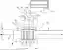


Sources:
- United States Patent and Trademark Office - verify current appl. status at the USPTO↗
Similar patent applications:
- » 20250050296
REACTION VESSEL, GAS PRODUCTION DEVICE, GAS PRODUCTION SYSTEM, AND GAS PRODUCTION METHOD - » 20240010500
GAS PRODUCTION DEVICE, GAS PRODUCTION SYSTEM AND GAS PRODUCTION METHOD - » 20240017233
GAS PRODUCTION DEVICE, GAS PRODUCTION SYSTEM, AND GAS PRODUCTION METHOD - » 20240416309
GAS PRODUCTION APPARATUS, GAS PRODUCTION SYSTEM, AND GAS PRODUCTION METHOD - » 20220144631
Gas production system and gas production method - » 20220305439
GAS PRODUCTION APPARATUS, GAS PRODUCTION SYSTEM, STEEL PRODUCTION SYSTEM, CHEMICAL PRODUCTION SYSTEM, AND GAS PRODUCTION METHOD - » 20230365414
GAS PRODUCTION APPARATUS, GAS PRODUCTION SYSTEM, AND GAS PRODUCTION METHOD - » 20220153579
GAS PRODUCTION SYSTEM AND GAS PRODUCTION METHOD - » 20200215478
Medical gas production system with gas recycling - » 20250270089
SYSTEM AND METHOD FOR PRODUCING HYDROGEN GAS FROM DIESEL FUEL USING A REFORMER OR OTHER HYDROGEN GAS PRODUCTION SYSTEM AND FOR MIXING THE HYDROGEN GAS BACK INTO THE LIQUID DIESEL FUEL PRIOR TO SENDING THE LIQUID DIESEL FUEL INTO A HYDRO-DIESEL ENGINE
Recent applications in this class:
- » 20260139384 2026-05-21
SYSTEM FOR RENEWABLE HYDROGEN PRODUCTION AND STORAGE USING AN ATMOSPHERIC WATER GENERATOR - » 20260132517 2026-05-14
AEROGEL-BASED FLOATABLE SELF-POWERED WATER-ELECTROLYSIS HYDROGEN GENERATION SYSTEM - » 20260132516 2026-05-14
WATER ELECTROLYSIS SYSTEM AND ENERGY SYSTEM - » 20260132515 2026-05-14
Hydrogen Gas Generation System - » 20260098347 2026-04-09
METHOD FOR IMPROVING EFFICIENCY OF WATER ELECTROLYSIS SYSTEM, APPARATUS AND SYSTEM THEREFOR - » 20260092378 2026-04-02
SLUDGE FORMATION DETECTION AND PREVENTION WITHIN A WATER ELECTROLYSIS INSTALLATION AND RELATED PROCESS - » 20260085430 2026-03-26
WATER ELECTROLYSIS SYSTEM - » 20260078498 2026-03-19
ELECTROLYSIS CELL, ELECTROLYSIS DEVICE, AND METHOD OF MANUFACTURING ELECTROLYSIS CELL - » 20260062816 2026-03-05
COMBINED SOLID OXIDE ELECTROLYZER CELL AND POLYMER ELECTROLYTE ELECTROLYZER CELL HYDROGEN GENERATION SYSTEM AND METHOD OF OPERATING THEREOF - » 20260055519 2026-02-26
ELECTROLYSIS APPARATUS OPERATION SYSTEM
Recent applications for this Assignee:
- » 20260132728 2026-05-14
EXHAUST AFTERTREATMENT SYSTEM WITH FILTER CARTRIDGE ASSEMBLY - » 20260118198 2026-04-30
AFTERTREATMENT SYSTEM WITH TUBE ASSEMBLY FOR PRESSURE SENSING - » 20260098491 2026-04-09
SYSTEMS AND METHODS FOR DOSER BIAS DETECTION IN AFTERTREATMENT SYSTEMS - » 20260071567 2026-03-12
REDUCTANT DELIVERY SYSTEM FOR EXHAUST GAS AFTERTREATMENT SYSTEM - » 20260049565 2026-02-19
VEHICLE SYSTEM WITH INJECTION HOUSING AND TURBOCHARGER HAVING MOTOR - » 20260028929 2026-01-29
SYSTEMS AND METHODS FOR MIXING EXHAUST GAS - » 20250376938 2025-12-11
AFTERTREATMENT SYSTEM INCLUDING DIFFERENTIAL PRESSURE SENSORS AND PRESSURE TUBE SEGMENTS - » 20250376936 2025-12-11
DOSER MOUNT FOR EXHAUST AFTERTREATMENT SYSTEM - » 20250374444 2025-12-04
CAPACITOR BANK ASSEMBLY FOR DEVICES USED IN AN AFTERTREATMENT SYSTEM - » 20250369383 2025-12-04
DOSER ASSEMBLY WITH SENSOR ASSEMBLY