GUARDRAIL
US20260146396A1
2026-05-28
19/393,918
2025-11-19
Smart Summary: A guardrail is made of two types of materials: metal and wood. The metal part consists of corrugated iron sections linked together and held up by posts. The wooden part is made of wooden rods, also connected and supported by posts. A special coupling system connects the metal and wooden parts, using a metal piece that attaches to the metal guardrail and a wooden piece that connects to the wooden guardrail. The metal piece has a box shape that securely holds the wooden piece in place. 🚀 TL;DR
Abstract:
A guardrail comprises a metal guardrail comprising corrugated iron sections connected to each other and supported by posts, a wooden guardrail comprising wooden rods connected to each other and supported by posts, and a coupling system connecting the metal guardrail to the wooden guardrail. The coupling system comprises a metal transition element suitable for being attached to one end of a corrugated iron section of the metal guardrail, and a wooden transition element suitable for being attached to a support provided in a post of the wooden guardrail. The metal transition element has a box shape that defines a seat wherein the wooden transition element is arranged and fixed.
Applicant:
Interested in similar patents?
Get notified when new applications in this technology area are published.
Classification:
E01F15/0423 » CPC main
Safety arrangements for slowing, redirecting or stopping errant vehicles, e.g. guard posts or bollards; Arrangements for reducing damage to roadside structures due to vehicular impact; Continuous barriers extending along roads or between traffic lanes essentially made of longitudinal beams or rigid strips supported above ground at spaced points; Metal rails Details of rails
E01F15/0453 » CPC further
Safety arrangements for slowing, redirecting or stopping errant vehicles, e.g. guard posts or bollards; Arrangements for reducing damage to roadside structures due to vehicular impact; Continuous barriers extending along roads or between traffic lanes essentially made of longitudinal beams or rigid strips supported above ground at spaced points Rails of materials other than metal or concrete, e.g. wood, plastics; Rails of different materials, e.g. rubber-faced metal profiles, concrete-filled steel tubes
E01F15/0461 » CPC further
Safety arrangements for slowing, redirecting or stopping errant vehicles, e.g. guard posts or bollards; Arrangements for reducing damage to roadside structures due to vehicular impact; Continuous barriers extending along roads or between traffic lanes essentially made of longitudinal beams or rigid strips supported above ground at spaced points Supports, e.g. posts
E01F15/0484 » CPC further
Safety arrangements for slowing, redirecting or stopping errant vehicles, e.g. guard posts or bollards; Arrangements for reducing damage to roadside structures due to vehicular impact; Continuous barriers extending along roads or between traffic lanes essentially made of longitudinal beams or rigid strips supported above ground at spaced points Installing; Repairing; Adjusting
E01F15/04 IPC
Safety arrangements for slowing, redirecting or stopping errant vehicles, e.g. guard posts or bollards; Arrangements for reducing damage to roadside structures due to vehicular impact; Continuous barriers extending along roads or between traffic lanes essentially made of longitudinal beams or rigid strips supported above ground at spaced points
Description
CROSS-REFERENCE TO RELATED APPLICATIONS
Not applicable.
FIELD OF THE INVENTION
The present invention relates to the field of road safety and, in particular, to a guardrail.
BACKGROUND OF THE INVENTION
Metal guardrails made of corrugated metal sheet supported by posts arranged at the edge of a road are known.
Wooden guardrails made of wooden bars supported by posts generally covered with wood, are also known.
However, mixed guardrails comprising a section of metal guardrail and a section of wooden guardrail are not known. In fact, the connection between the corrugated sheet metal of the metal guardrail and the wooden posts of the wooden guardrail is rather complex due to the transition between a corrugated profile consisting of the corrugated sheet metal of the metal guardrail and the wooden bars of the wooden guardrail that are perfectly straight and do not adjust to the corrugated profile of the metal guardrail.
EP2110479A1 discloses a transition and connection arrangement between two barriers of a vehicle safety barrier that are both made of metal.
SUMMARY OF THE INVENTION
The purpose of the present invention is to eliminate the drawbacks of the prior art by providing a mixed metal and wooden guardrail that is suitable for providing a connection between the metal guardrail and the wooden guardrail.
Another purpose of the present invention is to provide such a guardrail with a connection between the metal guardrail and the wooden guardrail that is efficient, reliable, versatile, practical, and easy to install.
Yet another purpose of the present invention is to provide such a guardrail with a connection between the metal guardrail and the wooden guardrail that is aesthetically pleasing and does not have a negative visual impact.
These purposes are achieved in accordance with the invention with the features of the attached independent claim 1.
Advantageous embodiments of the invention appear from the dependent claims.
BRIEF DESCRIPTION OF DRAWINGS
Further features of the invention will become clearer from the detailed description below, referring to a purely exemplary and therefore non-limiting embodiment, illustrated in the attached drawings.
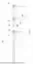
FIG. 1 is a front view illustrating the guardrail according to the invention.
FIG. 2 is a front perspective view illustrating the guardrail of FIG. 1, without the coupling system.
FIG. 3 is a rear perspective view illustrating the guardrail of FIG. 1, without the coupling system.
FIG. 4 is a view as in FIG. 2, with the addition of the coupling system with the wooden transition element in mounted condition, and an exploded view of the front and rear plates of the metal transition element.
FIG. 5 is a view as in FIG. 3, with the addition of the coupling system with the wooden transition element in mounted condition, and an exploded view of the front and rear plates of the metal transition element.
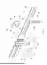
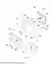
FIG. 6 is a front perspective view, illustrating the coupling system in an exploded view.
FIG. 7 is a rear perspective view, illustrating the coupling system in an exploded view.
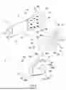
FIG. 8 is a perspective view, illustrating the metal transition element assembled on the corrugated sheet metal of the metal guardrail, and the wooden transition element in an exploded view.
FIG. 8A is view as in FIG. 8, illustrating broken lines that are not visible in the perspective view.
FIG. 9 is a front view of the coupling system assembled on a corrugated sheet of a metal guardrail.
FIG. 10 is a longitudinal sectional view taken along the horizontal sectional plane X-X of FIG. 9.
FIG. 11 is an enlarged view of a detail of FIG. 10.
FIG. 12 is a rear view of the coupling system assembled on a corrugated sheet of a metal guardrail.
DETAILED DESCRIPTION OF THE INVENTION
With the aid of the Figures, the guardrail according to the invention, which is generally indicated with reference numeral 100, is described.
The guardrail (100) comprises a metal guardrail (1), a wooden guardrail (2), and a coupling system (3) that connects the metal guardrail (1) to the wooden guardrail (2).
The metal guardrail (1) comprises corrugated iron sections (10) connected to each other and supported by posts (11).
The posts (11) are driven into the ground and the corrugated iron section (10) is supported by the posts (11) at a height (H) from the ground of generally 400-500 mm.
With reference to FIGS. 2 and 3, each corrugated iron section (10) has a front face (10a) facing the road, and a rear face (10b) opposite the front face (10a).
The front face (10a) of the corrugated iron section comprises a lower rib (12), an upper rib (13), and a central channel (14) disposed between the lower rib and the upper rib. In the central channel (14) there is a central rib (14b) having a lower height than the lower and upper ribs (12, 13). The ribs (12, 13, 14a) of the front face of the corrugated iron section extend horizontally parallel to each other.
The rear face (10b) of the corrugated iron section comprises a central rib (15), a lower channel (16), and an upper channel (17) corresponding respectively to the central channel (14) and to the lower and upper ribs (12, 13) of the front face of the corrugated iron section.
Each post (11) of the metal guardrail comprises a metal profile with H-shaped section. A support (18) with a parallelepiped shape is mounted on the upper part of each post (11) to secure the corrugated iron section (10).
The wooden guardrail (2) comprises wooden rods (20, 21) connected to each other and supported by posts (22). The wooden rods comprise two front rods (20) and two rear rods (21).
The posts (22) of the wooden guardrail comprise a metal profile (23) driven into the ground (T) and a wooden covering (24) arranged on the part of the metal profile protruding from the ground (T). The wooden covering (24) is arranged on a rear part of the metal profile (23).
A support (25) in the shape of a corrugated sheet is mounted on an upper part of each post (22) of the wooden guardrail to secure the front rods (20) by means of bolts (26). The rear rods (21) are secured to the front rods (20) by means of bolts (27).
In view of the above, each section of the wooden guardrail has two front rods (20) arranged horizontally and parallel to each other, and two rear rods (21) arranged behind the front rods (20).
With reference to FIG. 1, the coupling system (3) comprises a metal transition element (4) suitable for being attached to one end of a corrugated iron section (10) of the metal guardrail, and a wooden transition element (5) suitable for being attached to a support (25) arranged in a post (22) of the wooden guardrail.
With reference to FIG. 8, the metal transition element (4) has a box shape that defines a seat (40) wherein the wooden transition element (5) is arranged.
With reference to FIGS. 6 and 7, the metal transition element (4) comprises a front plate (6) and a rear plate (7) made of sheet metal.
The front plate (6) has a central portion (60) with isosceles trapezoidal shape having a major base (60a), a minor base (60b), and two oblique sides (60c, 60d).
A first side wing (61) protrudes from the central portion (60) to be engaged in the front face (10a) of the corrugated iron section (10). As shown in FIG. 8, the first side wing (61) of the front plate has a triangular shape and is arranged in the central channel (14) between the lower rib (12) and the upper rib (13) of the front face of the corrugated iron section (10). The first side wing (61) has a rounded tip with a recess (61a) that fits into the central rib (14a) of the front face of the corrugated iron section.
The first side wing (61) protrudes obliquely from the minor base (60b) of the central portion of the front plate at an angle of approximately 120°-160° with respect to the central portion (60).
A lower wing (62) and an upper wing (62) protrude from the central portion (60). Both the lower wing (62) and the upper wing (62) comprise a first portion (63a) and a second portion (63b) with different inclinations.
Two second side wings (64) protrude laterally from the major base (60a) of the central portion of the front plate in opposite direction to the first side wing (61). The central portion (60) of the front plate has a window (65) with U-shaped profile that starts centrally from the major base (60a) so as to divide the central portion into two portions from which the second side wings (64) protrude.
A central hole (66) is drilled in the central portion (60) and two side holes (67) are drilled in the second side wings (64).
The rear plate (7) comprises a first rectangular portion (70) that is arranged on the rear face (10b) of the corrugated iron section.
Two first side wings (71) protrude from the first portion (70) to be engaged in the lower channel (16) and in the upper channel (17) of the rear face of the corrugated iron section. The two first side wings (71) have a triangular shape. A space (72) is formed between the two first side wings (71), wherein the central rib (15) of the rear face of the corrugated iron section is arranged.
The first portion (70) is connected to a second portion (74) with isosceles trapezoidal shape by means of a connecting portion (73). The connecting portion (73) is step-shaped so that the second portion (74) is set back relative to the first portion (70).
Two second side wings (75) protrude from the second portion (74). A window (76) with U-shaped profile is provided between the second wings (75).
The second portion (74) of the rear plate comprises:
a plurality of holes (77) suitable for receiving self-tapping screws (V);
a central hole (78) suitable for receiving a central bolt (80);
two first peripheral holes (79) suitable for receiving first peripheral bolts (81); and
two second peripheral holes (79') for receiving first peripheral bolts (81).
The wooden transition element (5) comprises a body (50) having a substantially trapezoidal shape. Two blocks (51) having a rectangular section equal to the rectangular section of the front rods (20) of the wooden guardrail protrude from a major base of the body (50). The blocks (51) of the wooden transition element are arranged at a distance from each other that is equal to the distance between the front rods (20) of the wooden guardrail. In view of the above, the ends of the blocks (51) are arranged to abut against the ends of the front rods (20) of the wooden guardrail so as to give an impression of continuity of the wooden guardrail.
The wooden transition element (5) has a shaped front face (5a) and a flat rear face (5b).
The front face (5a) is shaped with a protruding profile (52) that defines a recessed seat (53) suitable for receiving the central portion (60) of the front plate. To this end, the protruding profile (52) defines two loops (54) that extend towards the blocks (51) to accommodate the second wings (64) of the front plate and a central protrusion (55) that is arranged in the window (65) of the front plate.
The body (50) of the wooden transition element has lower and upper edges comprising two portions (56, 57) that are inclined mutually so as to adjust to the different inclinations of the first portion (63a) and od the second portion (63b) of the lower wing (62) and of the upper wing (62) of the front plate which partially encloses the body (50) of the wooden transition element.
The second portion (74) of the rear plate rests on the rear face (5b) of the wooden transition element, which is flat. The self-tapping screws (V) are inserted into the holes (77) drilled in the second portion (74) of the rear plate and screwed into the body (50) of the wooden transition element.
The wooden transition element comprises:
a central through hole (58) disposed in the body (50) in central position;
two first peripheral through holes (59) disposed in the loops (54) of the recessed seat (53) and
two second peripheral through holes (59') disposed in the blocks (51).
With reference to FIG. 8A, in order to firmly secure the wooden transition element (5) to the metal transition element (4), in addition to the self-tapping screws (V), the following are used:
the central bolt (80) that enters the central holes (66, 58, 78) of the front plate, of the wooden transition element and of the rear plate, respectively and is screwed to a respective nut (80a) with washer (80b) arranged behind the rear plate (7);
the first two peripheral bolts (81) that are inserted into the peripheral holes (67) of the front plate and into the first peripheral holes (59, 79) of the wooden transition element and of the rear plate, respectively, and are screwed into respective nuts (81a) with washer (81b) disposed behind the rear plate (7); and
two second peripheral bolts (82) that are inserted into the second peripheral holes (59', 79') of the wooden transition element and of the rear plate, respectively, and are screwed to respective nuts (82a) with washer (82b) arranged behind the rear plate (7).
Together with the second peripheral bolts (82), tube-shaped spacers (9) with square section are inserted into the second peripheral holes (79') of the wooden transition element to prevent the wood from being crushed if the nut (82a) and the bolt (82) are excessively tightened, as well as to prevent the loosening of the bolt and the nut during the useful life of the guardrail in case of movements of the wood due to its hygroscopic nature. Furthermore, having a square cross-section, the spacer (9) acts as anti-rotation device for the bolt (82), which has a square neck, when the nut (82b) is tightened during the assembly on site.
Washers (82c) are arranged around the second peripheral bolts (82) in abutment with seats around the second peripheral holes (59') of the wooden transition element.
Numerous modifications can be made to the present embodiment of the invention, which are within the reach of an expert of the field and fall in any case within the scope of the invention as disclosed by the attached claims.
Claims
1. A guardrail comprising:
a metal guardrail comprising corrugated iron sections connected to each other and supported by posts;
a wooden guardrail comprising wooden rods connected to each other and supported by posts; and
a coupling system connecting the metal guardrail to the wooden guardrail;
wherein said coupling system comprises:
a metal transition element suitable for being attached to one end of a corrugated iron section of the metal guardrail; and
a wooden transition element suitable for being attached to a support provided in a post of the wooden guardrail;
wherein the metal transition element has a box shape that defines a seat wherein the wooden transition element is disposed and fixed.
2. The guardrail of claim 1, wherein said wooden guardrail comprises two front rods with a rectangular section fixed to said support of the wooden guardrail; and
wherein said wooden transition element comprises:
a body suitable for being arranged in said seat of the metal tradition element; and
two blocks having a rectangular section identical to the rectangular section of the front rods of the wooden guardrail; said blocks protruding from the body so that the ends of the blocks abut against the ends of the front rods of the wooden guardrail.
3. The guardrail of claim 1, wherein said metal transition element comprises a front plate and a rear plate made of sheet iron.
4. The guardrail of claim 2, wherein said metal transition element comprises a front plate and a rear plate made of sheet iron.
5. The guardrail of claim 4, wherein each corrugated iron sections has a front face facing the road that comprises a lower rib, an upper rib and a central channel between the lower rib and the upper rib; and
wherein the front plate of the metal transition element has a central portion suitable for being disposed on said body of the wood transition element, and a first side wing that protrudes from the central portion to be engaged in the central channel of the front face of the corrugated iron section.
6. The guardrail of claim 3, wherein each corrugated iron section has a rear face comprising a central rib disposed between a lower channel and an upper channel; and
wherein the rear plate has a first portion suitable for facing said rear face of the corrugated iron section, and two first side wings projecting from the first portion to be engaged in the lower and upper channels of the rear face of the corrugated iron section.
7. The guardrail of claim 4, wherein the front plate has a lower wing and an upper wing protruding from the central portion in such a way to be disposed on upper and lower edges of the body of said wood transition element.
8. The guardrail of claim 3, wherein said wood transition element has a shaped front face with a recessed seat suitable for accommodating said central portion of the front plate.
9. The guardrail of claim 5, wherein said wooden transition member has a flat rear face and said rear plate has a second portion connected to the first portion by means of a connecting portion; wherein the second portion of the rear plate abuts against the rear face of the wooden transition member.
10. The guardrail of claim 9, comprising self-tapping screws inserted into the holes drilled in said second portion of the rear plate and screwed into the body of said wood transition member.
11. The guardrail of claim 9, comprising bolts that are inserted into holes drilled in the front plate, in the body of the wooden transition element and in the second portion of the rear plate, respectively, and screwed into nuts disposed behind the second portion of the rear plate.
12. The guardrail of claim 9, comprising second peripheral bolts inserted into holes respectively drilled in the blocks of the wooden transition element and in second side wings protruding from the second portion of the rear plate to abut against said blocks of the wooden transition member; wherein said second peripheral bolts are screwed into respective nuts disposed behind said second side wings of the rear plate.
Images & Drawings included:


Sources:
- United States Patent and Trademark Office - verify current appl. status at the USPTO↗
Similar patent applications:
- » 20120211710
Guardrail assembly, breakaway support post for a guardrail and methods for the assembly and use thereof - » 20250076489
GUARDRAIL DETECTING APPARATUS AND GUARDRAIL DETECTING METHOD - » 20070228350
Guardrail assembly and method of installing the guardrail assembly - » 20110233495
Single-wave beam guardrail plate and single-wave beam steel guardrail - » 20180355567
One-piece metal plate foundation with integral offset plate for guardrails and other structures and guardrail system utilizing same - » 20240229388
GUARDRAIL TERMINAL AND GUARDRAIL ASSEMBLY - » 20060083588
Method for making a protective device for guardrails, and a protective device for guardrails - » 20070215849
Yielding post guardrail safety system incorporating thrie beam guardrail elements - » 20100243978
Guardrail assembly, breakaway support post for a guardrail and methods for the assembly and use thereof - » 20250257532
HIGHWAY GUARDRAIL, GUARDRAIL END SECTION, BARRIER WALL, CABLE BARRIER, AND TEMPORARY RAISED PAVEMENT REFLECTORS
Recent applications in this class:
- » 20260055563 2026-02-26
CRASH IMPACT ATTENUATOR SYSTEMS AND METHODS - » 20250059716 2025-02-20
CRASH IMPACT ATTENUATOR SYSTEMS AND METHODS - » 20230151570 2023-05-18
BARRIER SYSTEMS WITH IMPACT RESISTANT RAILS THAT EXTEND ALONG THE FLOOR - » 20230151569 2023-05-18
BARRIER SYSTEMS WITH IMPACT RESISTANT RAILS SUPPORTED FROM FLOOR MOUNTED POST BASES - » 20210115635 2021-04-22
Beam connection device - » 20190017236 2019-01-17
Energy absorption assembly - » 20180363259 2018-12-20
BARRIER SYSTEM AND METHOD OF USE THEREOF - » 20110155981 2011-06-30
Road rail - » 20110114909 2011-05-19
Guard rail including noise-reducing measures - » 20110084246 2011-04-14
Metal Roadway Safety Barrier