SADDLE FOR LIFTING SHOVEL AND METHOD THEREOF
US20260146401A1
2026-05-28
19/395,708
2025-11-20
Smart Summary: A shovel is designed with a special part called a saddle that helps connect it to a lifting mechanism. The saddle has two main surfaces: one that touches the lifting mechanism and another that fits the shape of the shovel's boom. The boom is the part of the shovel that can move up and down. A connecting piece holds the saddle and the shovel together securely. This setup makes it easier to lift and operate the shovel efficiently. 🚀 TL;DR
Abstract:
An assembly, has: a shovel having an upper part, a lower part, and a boom pivotally mounted to the upper part via a pin received through registering apertures of the upper part and the boom; and a system for interfacing a lifting mechanism to the shovel, the system having: a saddle defining an abutment face configured to be abutted by the lifting mechanism, a boom-engaging face opposite the abutment face, the boom-engaging face having a shape matching that of a portion of the boom; and a connecting member secured to both of saddle and the shovel, the shovel secured to the saddle via the connecting member.
Applicant:
Interested in similar patents?
Get notified when new applications in this technology area are published.
Classification:
E02F3/36 » CPC main
Dredgers; Soil-shifting machines mechanically-driven with digging tools mounted on a dipper- or bucket-arm, i.e. there is either one arm or a pair of arms , e.g. dippers, buckets Component parts
E02F3/308 » CPC further
Dredgers; Soil-shifting machines mechanically-driven with digging tools mounted on a dipper- or bucket-arm, i.e. there is either one arm or a pair of arms , e.g. dippers, buckets with a dipper-arm pivoted on a cantilever beam, i.e. boom working outwardly
E02F3/30 IPC
Dredgers; Soil-shifting machines mechanically-driven with digging tools mounted on a dipper- or bucket-arm, i.e. there is either one arm or a pair of arms , e.g. dippers, buckets with a dipper-arm pivoted on a cantilever beam, i.e. boom
Description
TECHNICAL FIELD
The application relates to a lifting system and method for safely raising and disassembling in multiple parts a shovel or raise it as a whole above a ground while maintaining it leveled to the ground.
BACKGROUND
Routine maintenance often requires that heavy equipment such as mechanical shovels be raised in elevation. This allows maintenance crews to access the obstructed components of the heavy equipment so as to perform maintenance and repairs and save time and effort by disassembling the upper part of the shovel from its lower tractor part, or by raising it as a whole.
For instance, a shovel typically has a lower car-body or tractor which uses continuous track motion to displace the shovel. In order to repair or perform maintenance on both of the upper part, also referred to as the house, and the lower part, also referred to as the car-body or tractor of the shovel, it would be desirable to access those components separately or at different height. Also, it is often required to separate the upper part from the car-body to perform maintenance on a pin, bushing, bearing or swing gears used to rotate the upper part relative to the lower part. This can be done by raising and/or disassembling the shovel in two parts.
SUMMARY
In one aspect, there is provided an assembly, comprising: a shovel having an upper part, a lower part, and a boom pivotally mounted to the upper part via a pin received through registering apertures of the upper part and the boom; and a system for interfacing a lifting mechanism to the shovel, the system having: a saddle defining an abutment face configured to be abutted by the lifting mechanism, a boom-engaging face opposite the abutment face, the boom-engaging face having a shape matching that of a portion of the boom; and a connecting member secured to both of saddle and the shovel, the shovel secured to the saddle via the connecting member.
The assembly described above may include any of the following features, in any combinations.
In some embodiments, the connecting member is a connecting arm extending from a saddle end secured to the saddle to a shovel end secured to the shovel.
In some embodiments, the connecting arm is one of two or more connecting arms, the two connecting arms defining at least three connection points between the saddle and the shovel.
In some embodiments, the at least three connection points include two connection points on the saddle and separated from one another and at least one connection point on the shovel.
In some embodiments, the saddle end of the connecting arm is pivotally mounted to the saddle.
In some embodiments, the shovel end of the connecting arm is secured to the pin.
In some embodiments, the shovel end defines an aperture sized to receive the pin therethrough.
In some embodiments, the shovel end defines two arcuate sections securable to one another, the two arcuate sections conjointly surrounding the pin.
In some embodiments, the shovel end defines an end plate abutted against an end face of the pin, the end plate secured to the end face.
In some embodiments, the connecting arm is variable in length.
In some embodiments, the connecting arm includes a first section defining inner threads and a second section defining outer threads threadingly engaged to the inner threads, rotation of the first section relative to the second section varying the length of the connecting arm.
In some embodiments, the connecting arm includes two sections slidable within another, the two sections lockable to one another via a pin received through registering apertures.
In some embodiments, the boom defines an aperture between opposite ends of the boom, the system further comprising a securing pin slidably received within the aperture of the boom, the connecting member secured to the securing pin.
In some embodiments, the connecting member is one of two connecting members disposed on opposite sides of the saddle and both secured to the saddle.
In some embodiments, the boom includes a member received between a pair of ribs of the upper part, the registering apertures defined by the ribs and the member.
In some embodiments, the member is one of two members, the pin is one of two or more pins, and the pair of the ribs is one of two pairs of the ribs, each of the two members received between a respective one of the two pairs of the ribs, each of the two members connected to a respective one of the pairs of the ribs via a respective one of the two pins.
In another aspect, there is provided a method of lifting a shovel having a lower part including endless tracks and an upper part supported by the lower part, and a boom pivotally mounted to the upper part via a pin, the method comprising: abutting a saddle against the boom; securing the saddle to the shovel with a connecting member; and lifting the upper part by exerting a lifting force on the upper part via the saddle.
The method described above may include any of the following features, in any combinations.
In some embodiments, the connecting member is a connecting arm extending from a saddle end to a shovel end, the method comprising pivotally connecting the saddle end to the saddle and connecting the shovel end to the shovel.
In some embodiments, the connecting arm is one of two or more connecting arms defining at least three connection points between the saddle and the shovel.
In some embodiments, the method of lifting a shovel having a lower part including endless tracks and an upper part supported by the lower part includes securing the two or more connecting arms at two of the at least three connection points on the saddle and securing the two or more connecting arms at at least one of the at least three connection points on the shovel.
DESCRIPTION OF THE DRAWINGS
Reference is now made to the accompanying figures in which:
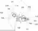
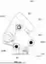
FIG. 1 is a side view of an electric shovel with a lifting mechanism engaged thereto in accordance with one embodiment and shown in a collapsed configuration;
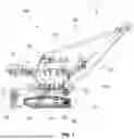
FIG. 2 is a side view of a system for interfacing a lifting mechanism to the shovel of FIG. 1;
FIG. 3 is a top three dimensional view of the system of FIG. 2;
FIG. 4 is a top view of the system of FIG. 2;
FIG. 5 is a side view of a possible embodiment of a shovel end of a connecting arm of the system of FIG. 2;
FIG. 6 is a side view of another possible embodiment of a shovel end of a connecting arm of the system of FIG. 2;
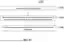
FIG. 7 is a side partially transparent view of a possible embodiment of a connecting arm;
FIG. 8 is a side view of another possible embodiment of a connecting arm;
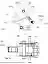
FIG. 9 is a side view of a system in accordance with another embodiment for interfacing a lifting mechanism to another embodiment of a shovel;
FIG. 10 is a top view of the system of FIG. 9;
FIG. 11 is a side view of a system in accordance with another embodiment for interfacing a lifting mechanism to the shovel of FIG. 9;
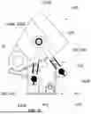
FIG. 12 is a side view of a system in accordance with another embodiment for interfacing a lifting mechanism to the shovel of FIG. 9; and
FIG. 13 is a flowchart illustrating steps of a method of lifting a shovel.
DETAILED DESCRIPTION
There is described herein an apparatus and a method to lift or raise heavy machinery in whole or in parts. The apparatus coordinates the lifting of the heavy machinery so that it can be raised with respect to a ground surface. In so doing, the apparatus provides clearance so that vehicles and maintenance crews are able to access the obstructed ends of the heavy machinery and suspends the heavy machinery at an elevation while the maintenance operation is being performed.
As will be seen hereinafter, the apparatus and method are particularly useful for safely lifting heavy machinery, such as hydraulic or electrical shovels. FIG. 1 illustrates one example of such a shovel 10, being an electric shovel. The shovel 10 generally comprises an upper part 11 secured to a lower part 12. Typically, the upper part 11 may include motorization of the shovel 10. However, in some embodiments, some components of the motorization may be contained in the lower part 12. The lower part 12 comprises a car-body 13 having a side frame 13A on each side. Each of the side frames 13A have rollers which turn endless tracks 14 or treads to displace the shovel on a ground surface. The endless tracks 14 may be replaced by wheels in some embodiments. A rolling circle 15 is secured between the upper part 11 and the lower part 12 to allow the upper part 11 to revolve 360 degrees around a central axis of the shovel 10 in either direction, clockwise or counterclockwise, and relative to the car-body 13. In the front of the upper part 11 are mounted a front attachments 20, which usually consist of a boom 21 pivotably mounted to the upper part 11. Although not illustrated, a bucket or other implement may be operatively connected at a distal end of the boom 21. The boom 21 is moved using cables 22 and winch 23 engaged to those cables 22. Pulleys or other mechanism may be used. The winch 23 is able to exert a force on the cables 22 to rotate the boom 21 relative to the upper part 11.
At regular intervals, the shovel 10 may need to be lifted as a whole or the upper part 11 separated from the lower part 12 for servicing of their components. For instance, the rollers of the car-body 13 need to be replaced at regular intervals. Similarly, the side frames 13A of the car-body 13 eventually also require repairs or replacement. This type of maintenance requires a lot of time and effort and in doing so, there is a great incentive to be able to lift or separate the shovel 10 in a safe and easy manner. While it is possible to do so with lifts using large capacity hydraulic jacks, there is always room for improvement.
Still referring to FIG. 1, a lifting system used for lifting the upper part 11 relative to the car-body 13 is shown. The lifting system includes a rear lifting system 30 and a front lifting system 40. These systems are described in Ser. No. 18/917,107 filed on Oct. 16, 2024, the entire contents of which are incorporated by reference herein. The principles of the present disclosure may be used with any lifting system. These lifting systems may include actuators, such as hydraulic actuators, operable to exert a lifting force on the upper part 11 to separate it from the lower part 12. The front lifting system 40 may have a width, which is transverse to a direction of travel of the shovel 10, being less than a distance between the endless tracks 14.
Referring to FIGS. 2-3, in some embodiments, the boom 21 includes one, two, or more members 21A, only one being depicted, each received between ribs 11A of a pair of ribs. A pin 24 extends through registering apertures defined by both of the ribs 11A and the member(s) 21A. This pin 24 therefore provides a pivotal connection between the boom 21 and the upper part 11.
The front lifting system 40 may be abutted against connection points between the boom 21 and the upper part 11. However, the shape of these connection points may cause slippage of the front lifting system 40 when a lifting force is applied. The present disclosure describes an interface system to be secured to the shovel 10 and used as an interface between the shovel 10 and the front lifting system 40. As mentioned above, it is typically not possible to abut directly the front lifting system 40 to the boom 21 since a shape of a surface of the boom 21 may be angled. This may cause the top of lifting system 40 to slip forward and away from the upper part 11. It may be possible to weld lugs to the upper part 11 and mount a saddle to those lugs. The role of the saddle is to create an interface between the front lifting system 40 and the boom 21. However, welding such lugs requires time consuming tasks and it may be required to dismount the boom 21 and/or to remove those lugs after maintenance on the shovel 10 is completed.
Referring to FIGS. 2-4, a system for interfacing the front lifting system or mechanism 40 to the shovel 10 is shown at 100. The system 100 may alleviate the aforementioned drawbacks.
The system 100 includes a saddle 110 and one or more, two in this embodiment, connecting members, depicted as connecting arms 120, for securing the saddle 110 to the shovel 10. The system 100 may include more than one saddle 110, typically, one saddle per member 21A of the boom 21. In some cases, only one saddle is used that sized to accommodate more than one member 21A of the boom. The saddle 110 has a body defining an abutment face 111, which is oriented downwardly towards a ground, and configured to be abutted by the front lifting system 40 and a boom-engaging face 112 opposite the abutment face 111 and which is oriented generally upwardly away from the ground. The abutment face 111 has a shape configured to mate with the front lifting system 40. In this embodiment, the abutment face 111 is substantially flat and levelled relative to the ground. Hence, the front lifting system 40 may push against the saddle 110 while avoiding slippage between them. The boom-engaging face 112 has a shape matching that of a portion of the boom 21. As shown in FIG. 2, and in some embodiments, the boom-engaging face 112 is arcuate and concave. Its shape matches that of a lower end of the member 21A of the boom 21. The boom-engaging face 112 may define a concave section configured to be engaged by the lower end of the member 21A. This engagement between the concave section and the lower end may contribute in stabilizing the saddle 110 to the boom 21.
However, the system 100 has features to further block movements of the saddle 110 relative to the boom 21. In some embodiments, the saddle 110 further has two lugs 113 secured to a front end of the saddle 110, although only one lug may be used in some cases. Herein, expressions “front” and “rear” are in relationship to a direction of travel T (FIG. 1) of the shovel 10. The connecting arms 120 are mounted to the saddle 110 via the two lugs 113 as will be described below. The two lugs 113 may be omitted in some configurations and the saddle 110 may define bores via which the connecting arms 120 may be secured.
Each of the connecting arms 120, two arms in this embodiment, but more or less may be used, extends from a saddle end 121 removably securable to the saddle 110 to a shovel end 122 removably securable to the shovel 10, herein to the upper part 11 of the shovel 10. In the depicted embodiment, the connecting arms 120 are pivotally mounted to the two lugs 113 via a connecting pin 123. A single connecting pin may be used and may extend through apertures of the two lugs 113 and through apertures defined at the saddle end 121 of the connecting arms 120. One connecting pin for each of the connecting arms 120 may be used in some embodiments. Hence, the saddle end 121 of the connecting arm 120 is pivotally mounted to the saddle 110. Alternatively, the connecting arms 120 may be fixedly connected to the saddle 110. The connecting arms 120 may be an integral part of the saddle 110 such that the connecting arms 120 and the saddle 110 are two parts of a single monolithic body.
Referring more particularly to FIGS. 2-5, the shovel ends 122 of the connecting arms 120 are secured to the pins 24 that connects the boom 21 to the upper part 11. The system 100 therefore permits the use of an element that is part of the shovel 10 for securing the saddle 110. As illustrated in FIG. 5, the shovel end 122 of the connecting arms 120 defines an aperture 122A sized to receive an end of the pin 24 therethrough. In some cases, the connecting arms 120 may be moved axially relative to a central axis of the pin 24 to insert the pin 24 in the apertures 122A of the shovel ends 122 of the connecting arms 120. However, in this embodiment, the shovel end 122 defines two arcuate sections 122B securable to one another via suitable fasteners 122C for instance. The two arcuate sections 122B conjointly surround the pin 24.
Another embodiment of a connecting arm is shown at 220 in FIG. 6. In this embodiment, the shovel end 222 of the connecting arm 220 defines an end plate 222A that may be abutted against an end face 24A (FIG. 4) of the pin 24. The end plate 222A may be secured to the end face 24A via fasteners 222C, four in this embodiment but more or less may be used.
Referring to FIGS. 7-8, the connecting arm 120 may be variable in length. This need not be the case in all embodiments. To this end, the connecting arm 120 includes two sections 120A, 120B that are movable linearly one relative to the other to adjust a length of the connecting arm 120; the length being defined from the shovel end 122 to the connecting saddle end 121. In the embodiment of FIG. 7, the first section 120A defines inner threads 120C and the second section 120B defines outer threads 120D threadingly engaged to the inner threads 120C. Thus, rotation of the two sections 120A, 120B one relative to the other varies the length of the connecting arm 120.
In the embodiment of FIG. 8, the two sections 120A, 120B may be slidable one within the other and lockable to one another via a locking pin 120E, which is removably received within registering apertures defined through the two sections. In this embodiment, one of the two sections define a series of apertures 120F distributed axially along a length of the connecting arm and the other of the two sections may define an aperture. Length is selected by aligning one of the apertures of the series of apertures 120F with the aperture defined by the other section and by inserting the locking pin 120E through the registering apertures. The locking pin 120E may be in the form of a bolt and nut of proper diameter or any other type of lock pin know in the art. Any means for changing the length of the connecting arms is contemplated without departing from the scope of the present disclosure. In some embodiments, the connecting arms may have a fixed length. Any suitable ways of interconnecting the two sections of the arms in a variable length fashion is contemplated.
Referring to FIGS. 9-10, another embodiment of a system for interfacing the front lifting system 40 to the shovel 10 is shown at 300. For the sake of conciseness, only features differing from the system 100 described above are described below.
In the embodiment shown, the shovel has a different type of boom, which has members referred to with reference numeral 321A. These members 321A may each define an aperture 321B therethrough. This aperture 321B may be leveraged for securing the saddle 310 to the boom 21. Only one saddle 310 may be used or more than one saddle—one saddle per member 321A—in some embodiments. In some cases, only one saddle is used that sized to accommodate more than one member of the boom. As described above, the saddle 310 has an abutment face 311 for interfacing with the lifting system and a boom-engaging face 312 to abut the boom 21 as described above. The boom-engaging face 312 defines a recess, or concave portion, shaped for receiving an end of the member 321A. In this embodiment, the connecting arms 320 are secured to both of the saddle 310 as described above using the lugs 313 and a connecting pin 343, which are similar to the lugs 113 and connecting pins 123 described above with reference to FIG. 2, and to the member 321A of the boom via a securing pin 323 extending through registering apertures of the shovel ends of the connecting arms 320 and of the aperture 21B of the boom 21. The securing pin 323 is slidably received within these apertures. The securing pin 323, the connecting pin 343, and the pin 24 are all radially offset from one another. In other words, each of those pins has a central axis that are non-coincident relative to each other.
It has been observed by the inventors of the present disclosure that, in some cases, a force applied to the saddle 310 may translate in a moment exerted on the saddle 310 in a counterclockwise direction. This may result in a compressive force being exerted on the connecting arm(s) 320. This may be undesired because the connecting arm(s) 320 may not be designed to work in compression and may be subject to buckling in some rare instances. When the moment is exerted in a clockwise direction on the saddle 310, the connecting arm(s) 320 act in tension as desired.
Referring now to FIG. 11, another embodiment of a system is shown at 400. The system 400 may at least partially alleviate the aforementioned drawbacks. For the sake of conciseness, only features differing from the embodiment 300 described here and above with reference to FIGS. 9 and 10 are described herein below.
In this embodiment, the system 400 for interfacing the lifting mechanism 40 to the shovel 10 is modified to include two connecting arms 120, namely a first connecting 424 and a second connecting arm 425 each extending between first and second ends 424A, 424B, 425A, 425B. The connecting arms 424, 425 therefore define at least three distinct connection points between the member 321A of the boom and the saddle 410. It will be appreciated that more than three connection points, such as two or more on the member of the boom and two or more on the saddle, may be used in some embodiments. In some embodiments, the second ends 424B, 425B of the first connecting arm 424 and the second connecting arm 425 are both secured to the same securing pin 323 to interconnect the connecting arms 424, 425 to the boom 21. Hence, these two ends 424B, 425B are coincident. However, this need not be the case and the second end 425B of the second connecting arm 425 may be secured to the boom 21 at another location, such as to the pin 24. Other locations are contemplated.
The first end 424A of the first connecting arm 424 may be secured to the lug 413, similar to the lugs 113 of FIG. 2, via the connecting pin 423, similar to the connecting pin 123 of FIG. 2, whereas the first end 425A of the second connecting arm 425 may be secured to the saddle 410 via a second connecting pin 443. The second connecting pin 443 may be an integral part of the saddle 410, or may be a separate component slidably engaged to the saddle 410 via an aperture defined through the saddle 410.
Both of the two connecting arms 424, 425 may be variable in length as described herein above with reference to FIGS. 7-8. However, this need not be the case for all embodiments. It will be appreciated that, in some embodiments, these two connecting arms may be duplicated on the other side of the member of the boom 21 for increased stability, although this may not be required.
Referring now to FIG. 12, another embodiment of a system is shown at 500. For the sake of conciseness, only features differing from the embodiment 500 described here and above with reference to FIG. 11 are described herein below.
In the embodiment shown, the system 500 includes one or more connecting members 520 for securing the member 321A of the boom to the saddle 410. The connecting member 520 has a triangular shape, although other shapes are contemplated. The connecting member 520 defines three attachment points, namely a first attachment point 520A, a second attachment point 520B, and a third attachment point 520C. In the depicted embodiment, the first attachment point 520A may be secured to the saddle 410 via the lugs 413 and the connecting pin 423 (similar to the lugs 113 and connecting pin 123 of FIG. 2). The second attachment point 520B may be secured to the saddle 410 via the second connecting pin 443 described above with reference to FIG. 11, and the third connecting point 520C may be secured to the member 21A of the boom 21 via the securing pin 323 described above with reference to FIG. 9.
As for the two connecting arms described above with reference to FIG. 11, the connecting member 520 includes three attachment points that may ensure that there is always a portion of the connecting member 520 that is solicited by tension as opposed to compression. This may ensure that the connecting member 520 does not bend under a compressive force if there is a relative motion of the member 21A of the boom 21 relative to the saddle 410.
Referring now to FIG. 13, a method of lifting the shovel 10 is shown at 1300. The method 1300 includes abutting the saddle 110, 310 against the boom 21 at 1302; securing the saddle 110, 310 to the shovel 10 with the connecting arm(s) 120, 220, 320 secured at a saddle end to the saddle and at a shovel end to the shovel 10 at 1304; and lifting the upper part 11 by exerting a lifting force on the upper part 11 via the saddle 110, 310.
In some embodiments, the method 1300 includes pivotally connecting the saddle end of the connecting arms to the saddle. The securing of the shovel end to the shovel 10 may include securing the shovel end of the connecting arm to the pin 24 received through the registering apertures defined by the boom 21 and the upper part 11. The securing of the shovel end to the pin 24 may include inserting the pin 24 into the aperture of the shovel end.
As illustrated in FIGS. 4-5, the inserting of the pin 24 into the aperture may include enclosing the pin 24 between the two arcuate sections 122B securable to one another. Alternatively, as shown in FIGS. 4 and 6, the securing of the shovel end to the pin 24 may include securing the end plate 222A defined by the shovel end of the connecting arm 220 to the end face 24A of the pin 24.
As shown in FIGS. 7-8, the method 1300 may include adjusting the length of the connecting arm 120, 220, 320. This may be done by rotating the first section 120A of the connecting arm 120 relative to the second section 120B of the connecting arm 120. Inner and outer threads defined by the sections cooperate to create a translating linear motion of these two sections relative to one another to adjust the length. Alternatively, and as shown in FIG. 8, the adjusting of the length may include sliding two sections 120A, 120B of the connecting arm 120 relative to one another and locking the two sections to each other with the locking pin 120E received through registering apertures 120F of the two sections.
As shown in FIGS. 9-10, the securing the saddle 310 to the shovel 10 may include securing the shovel end to the boom 21 via the securing pin 323 extending through the aperture 21B defined by the boom 21.
It is noted that various connections are set forth between elements in the preceding description and in the drawings. It is noted that these connections are general and, unless specified otherwise, may be direct or indirect and that this specification is not intended to be limiting in this respect. A coupling between two or more entities may refer to a direct connection or an indirect connection. An indirect connection may incorporate one or more intervening entities. The term “connected” or “coupled to” may therefore include both direct coupling (in which two elements that are coupled to each other contact each other) and indirect coupling (in which at least one additional element is located between the two elements).
It is further noted that various method or process steps for embodiments of the present disclosure are described in the preceding description and drawings. The description may present the method and/or process steps as a particular sequence. However, to the extent that the method or process does not rely on the particular order of steps set forth herein, the method or process should not be limited to the particular sequence of steps described. As one of ordinary skill in the art would appreciate, other sequences of steps may be possible. Therefore, the particular order of the steps set forth in the description should not be construed as a limitation.
Furthermore, no element, component, or method step in the present disclosure is intended to be dedicated to the public regardless of whether the element, component, or method step is explicitly recited in the claims. As used herein, the terms “comprises”, “comprising”, or any other variation thereof, are intended to cover a non-exclusive inclusion, such that a process, method, article, or apparatus that comprises a list of elements does not include only those elements but may include other elements not expressly listed or inherent to such process, method, article, or apparatus.
While various aspects of the present disclosure have been disclosed, it will be apparent to those of ordinary skill in the art that many more embodiments and implementations are possible within the scope of the present disclosure. For example, the present disclosure as described herein includes several aspects and embodiments that include particular features. Although these particular features may be described individually, it is within the scope of the present disclosure that some or all of these features may be combined with any one of the aspects and remain within the scope of the present disclosure. References to “various embodiments,” “one embodiment,” “an embodiment,” “an example embodiment,” etc., indicate that the embodiment described may include a particular feature, structure, or characteristic, but every embodiment may not necessarily include the particular feature, structure, or characteristic. Moreover, such phrases are not necessarily referring to the same embodiment. The use of the indefinite article “a” as used herein with reference to a particular element is intended to encompass “one or more” such elements, and similarly the use of the definite article “the” in reference to a particular element is not intended to exclude the possibility that multiple of such elements may be present.
The embodiments described in this document provide non-limiting examples of possible implementations of the present technology. Upon review of the present disclosure, a person of ordinary skill in the art will recognize that changes may be made to the embodiments described herein without departing from the scope of the present technology. Yet further modifications could be implemented by a person of ordinary skill in the art in view of the present disclosure, which modifications would be within the scope of the present technology.
Claims
1. An assembly, comprising:
a shovel having an upper part, a lower part, and a boom pivotally mounted to the upper part via a pin received through registering apertures of the upper part and the
boom; and
a system for interfacing a lifting mechanism to the shovel, the system having:
a saddle defining an abutment face configured to be abutted by the lifting mechanism, a boom-engaging face opposite the abutment face, the boom-engaging face having a shape matching that of a portion of the boom; and
a connecting member secured to both of saddle and the shovel, the shovel secured to the saddle via the connecting member.
2. The assembly of claim 1, wherein the connecting member is a connecting arm extending from a saddle end secured to the saddle to a shovel end secured to the shovel.
3. The assembly of claim 2, wherein the connecting arm is one of two or more connecting arms, the two connecting arms defining at least three connection points between the saddle and the shovel.
4. The assembly of claim 3, wherein the at least three connection points include two connection points on the saddle and separated from one another and at least one connection point on the shovel.
5. The assembly of claim 2, wherein the saddle end of the connecting arm is pivotally mounted to the saddle.
6. The assembly of claim 5, wherein the shovel end of the connecting arm is secured to the pin.
7. The assembly of claim 6, wherein the shovel end defines an aperture sized to receive the pin therethrough.
8. The assembly of claim 7, wherein the shovel end defines two arcuate sections securable to one another, the two arcuate sections conjointly surrounding the pin.
9. The assembly of claim 6, wherein the shovel end defines an end plate abutted against an end face of the pin, the end plate secured to the end face.
10. The assembly of claim 2, wherein the connecting arm is variable in length.
11. The assembly of claim 10, wherein the connecting arm includes a first section defining inner threads and a second section defining outer threads threadingly engaged to the inner threads, rotation of the first section relative to the second section varying the length of the connecting arm.
12. The assembly of claim 10, wherein the connecting arm includes two sections slidable within another, the two sections lockable to one another via a pin received through registering apertures.
13. The assembly of claim 1, wherein the boom defines an aperture between opposite ends of the boom, the system further comprising a securing pin slidably received within the aperture of the boom, the connecting member secured to the securing pin.
14. The assembly of claim 1, wherein the connecting member is one of two connecting members disposed on opposite sides of the saddle and both secured to the saddle.
15. The assembly of claim 14, wherein the boom includes a member received between a pair of ribs of the upper part, the registering apertures defined by the ribs and the member.
16. The assembly of claim 15, wherein the member is one of two members, the pin is one of two or more pins, and the pair of the ribs is one of two pairs of the ribs, each of the two members received between a respective one of the two pairs of the ribs, each of the two members connected to a respective one of the pairs of the ribs via a respective one of the two pins.
17. A method of lifting a shovel having a lower part including endless tracks and an upper part supported by the lower part, and a boom pivotally mounted to the upper part via a pin, the method comprising:
abutting a saddle against the boom;
securing the saddle to the shovel with a connecting member; and
lifting the upper part by exerting a lifting force on the upper part via the saddle.
18. The method of claim 17, wherein the connecting member is a connecting arm extending from a saddle end to a shovel end, the method comprising pivotally connecting the saddle end to the saddle and connecting the shovel end to the shovel.
19. The method of claim 18, wherein the connecting arm is one of two or more connecting arms defining at least three connection points between the saddle and the shovel.
20. The method of claim 19, comprising securing the two or more connecting arms at two of the at least three connection points on the saddle and securing the two or more connecting arms at at least one of the at least three connection points on the shovel.
Images & Drawings included:


Sources:
- United States Patent and Trademark Office - verify current appl. status at the USPTO↗
Recent applications in this class:
- » 20250092632 2025-03-20
CORNER SEGMENT - » 20210017733 2021-01-21
DIMENSION-SPECIFYING DEVICE AND DIMENSION-SPECIFYING METHOD - » 20200340202 2020-10-29
Front loader - » 20190194902 2019-06-27
Front loader - » 20190177946 2019-06-13
Double safety device for quick coupler - » 20190010675 2019-01-10
SHOVEL - » 20180355578 2018-12-13
FLUID CONVEYANCE SYSTEM FOR INDUSTRIAL MACHINE - » 20180179726 2018-06-28
Work implement, arm, and work vehicle - » 20180080190 2018-03-22
System and method for vibration monitoring of a mining machine - » 20170089028 2017-03-30
Front loader