DETERMINING THAT A TARGET IS NOT A PREDICTED DESTINATION OF A PROJECTED PATH OF A MACHINE
US20260146403A1
2026-05-28
18/961,949
2024-11-27
Smart Summary: A machine is equipped with tools and sensors that help it understand its surroundings. It uses these sensors to figure out if something is in its path at a specific moment. Initially, the machine may think that the object is in its way. However, after checking again later, it can realize that the object is no longer in its path. This ability helps the machine avoid obstacles and navigate more safely. 🚀 TL;DR
Abstract:
A machine includes: an implement and a linkage, a perception sensor system that includes one or more perception sensors, a machine sensor system that includes one or more machine sensors, and a controller. The controller obtains first perception information from the perception sensor system and determines, based on the first perception information, that a target is a predicted destination of a projected path of the machine at a first instant in time. The controller obtains, after determining that the target is the predicted destination of the projected path of the machine at the first instant in time, second perception information from the perception sensor system. The controller determines, based on the second perception information, that the target is not the predicted destination of the projected path of the machine at a second instant in time.
Inventors:
- Tonglin Shang 42 🇺🇸 Bolingbrook, IL, United States
- Aleksandar M. Egelja 21 🇺🇸 Naperville, IL, United States
- Shaun D. Currier 13 🇺🇸 Naperville, IL, United States
- Michael Anthony SPIELMAN, Jr. 4 🇺🇸 Osseo, MI, United States
- Darren Allan BLUM 4 🇺🇸 Plainfield, IL, United States
- Aleksander Franklin GUST 4 🇺🇸 Orland Park, IL, United States
- Jeffrey Kent BERRY 2 🇺🇸 Clayton, NC, United States
Assignee:
- Caterpillar Inc. 8,369 🇺🇸 Peoria, IL, United States
Applicant:
Interested in similar patents?
Get notified when new applications in this technology area are published.
Classification:
E02F3/431 » CPC main
Dredgers; Soil-shifting machines mechanically-driven with digging tools mounted on a dipper- or bucket-arm, i.e. there is either one arm or a pair of arms , e.g. dippers, buckets; Component parts; Drives for dippers, buckets, dipper-arms or bucket-arms; Control of dipper or bucket position; Control of sequence of drive operations for bucket-arms, front-end loaders, dumpers or the like
E02F3/342 » CPC further
Dredgers; Soil-shifting machines mechanically-driven with digging tools mounted on a dipper- or bucket-arm, i.e. there is either one arm or a pair of arms , e.g. dippers, buckets with bucket-arms, i.e. a pair of arms, e.g. manufacturing processes, form, geometry, material of bucket-arms directly pivoted on the frames of tractors or self-propelled machines Buckets emptying overhead
E02F3/43 IPC
Dredgers; Soil-shifting machines mechanically-driven with digging tools mounted on a dipper- or bucket-arm, i.e. there is either one arm or a pair of arms , e.g. dippers, buckets; Component parts; Drives for dippers, buckets, dipper-arms or bucket-arms Control of dipper or bucket position; Control of sequence of drive operations
Description
TECHNICAL FIELD
The present disclosure relates generally to a machine and, for example, to determining that a target is not a predicted destination of a projected path of the machine.
BACKGROUND
To perform a dumping operation, a machine, such as a wheel loader, can use an implement (e.g., a bucket or another implement) to load and to carry a material (e.g., asphalt, debris, dirt, snow, feed, gravel, logs, raw minerals, recycled material, rock, sand, woodchips, or similar material) and to dump the material into a dump target (e.g., another machine, such as a dump truck). The machine can include perception sensors to detect a position of the dump target, such as to enable an automated implement lift operation. For example, a controller of the machine can use the perception sensors to identify when the machine is sufficiently near the dump target, and thereby automatically cause the implement to raise to a height to enable an efficient dumping of material from the implement into the dump target when the machine reaches the dump target.
However, in many cases, a dump target is not an intended destination of the machine, such as when the machine is manually operated by an operator. For example, despite the operator's intention drive the machine past the dump target, the controller may identify the dump target as a destination of the machine (e.g., due to the target being in a field of view of the perception sensors of the machine). This results in the automated implement lift operation unnecessarily being performed when the machine approaches sufficiently near the dump target, even though the operator intends to drive the machine past the dump target. Consequently, the implement is lifted to a high position at an inappropriate time (e.g., when the machine passes the dump target to travel elsewhere, such as to another dump target), which results in an elevated center of gravity of the machine (e.g., as the machine travels with the implement in the high position). This can reduce a stability and a control of the machine, which can lead to spillage of a material carried by the machine. Further, unnecessary lifting of implement, when carrying a heavy load of material, can increase wear and tear on the implement and on a linkage that connects the implement to the machine, which can impact a performance of, as well as reduce an operable life of, the implement and the linkage, and the machine.
The controller of the present disclosure solves one or more of the problems set forth above and/or other problems in the art.
SUMMARY
In some implementations, a machine comprises: an implement and a linkage; a perception sensor system that includes one or more perception sensors; a machine sensor system that includes one or more machine sensors; and a controller configured to: obtain first perception information from the perception sensor system; determine, based on the first perception information, that a target is a predicted destination of a projected path of the machine at a first instant in time; obtain, after determining that the target is the predicted destination of the projected path of the machine at the first instant in time, second perception information from the perception sensor system; and determine, based on the second perception information, that the target is not the predicted destination of the projected path of the machine at a second instant in time.
In some implementations, a controller of a machine includes one or more memories; and one or more processors, coupled to the one or more memories, configured to: determine, based on first perception information obtained from a perception sensor system of the machine, that a target is a predicted destination of a projected path of the machine at a first instant in time; determine, based on determining that the target is the predicted destination of the projected path of the machine at the first instant in time, that a distance from the machine to the target satisfies a distance threshold; and determine, based on determining that the distance from the machine to the target satisfies the distance threshold, and based on at least one of the first perception information or second perception information obtained from the perception sensor system, that the target is not the predicted destination of the projected path of the machine at a second instant in time.
In some implementations, a method includes determining, by a controller of a machine, that a distance from the machine to a target, which is a predicted destination of a projected path of the machine at a first instant in time, satisfies a distance threshold; and determining, by the controller, based on determining that the distance from the machine to the target satisfies the distance threshold, and based on perception information obtained from a perception sensor system of the machine, that the target is not the predicted destination of the projected path of the machine at a second instant in time.
BRIEF DESCRIPTION OF THE DRAWINGS
FIG. 1 is a diagram of an example machine described herein.
FIG. 2 is a diagram of an example configuration of the front of the machine.
FIGS. 3A-3D are diagrams of an example implementation described herein.
FIGS. 4A-4B are diagrams of an example implementation described herein.
FIG. 5 is a diagram of example components of a device associated with determining that a target is not a predicted destination of a projected path of a machine.
DETAILED DESCRIPTION
This disclosure relates to a controller of a machine (e.g., that performs a dumping operation) and is applicable to any machine that is capable of loading and moving material (e.g., from a first location to a second, different location) and/or dumping the material (e.g., into a dump target). For example, the machine may be any machine that performs an operation associated with an industry such as, for example, mining, construction, farming, transportation, or any other industry. As some examples, the machine may be a vehicle, a wheel loader, a backhoe loader, a cold planer, a compactor, a feller buncher, a forest machine, a forwarder, a harvester, an excavator, an industrial loader, a knuckleboom loader, a material handler, a motor grader, a pipelayer, a road reclaimer, a skid steer loader, a tractor, a dozer, a tractor scraper, or other above ground equipment, underground equipment, aerial equipment, or marine equipment.
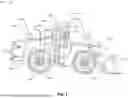
FIG. 1 is a diagram of an example machine 100 described herein. For example, the machine 100 may include a mobile machine, such as the wheel loader shown in FIG. 1, or any other type of mobile machine. Further, the machine 100 may be a manned machine or an unmanned machine, and/or may be fully autonomous, semi-autonomous, or remotely operated.
As shown, the machine 100 may have a frame 102 that supports an operator station 104, a power system 106, a drive system 108, an implement 110, a perception sensor system 112, and a controller 114. The operator station 104 may include operator controls 116 for operating the machine 100 via the power system 106. In some examples, the machine 100 may not include an operator station 104 and/or operator controls 116 (e.g., the machine 100 may be controlled via other means, such as a remote control system). The operator station 104 may be configured to define an interior cabin 118 within which the operator controls 116 are housed.
The power system 106 is configured to supply power to the machine 100. The power system 106 may be operably arranged to receive control signals from the operator controls 116 in the operator station 104 and/or from the controller 114. Additionally, or alternatively, the power system 106 may be operably arranged with the drive system 108 and/or the implement 110 to selectively operate the drive system 108 and/or the implement 110 according to the control signals. The power system 106 may provide operating power for the propulsion of the drive system 108 and/or the operation of the implement 110. The power system 106 may include an engine, a motor, an electric drive, a fuel cell, and/or another type of power system.
The drive system 108 may be operably arranged with the power system 106 to selectively propel the machine 100 via the control signals. The drive system 108 can include a plurality of ground-engaging members, such as wheels 120, as shown, which can be movably connected to the frame 102 through axles, drive shafts, and/or other components. The drive system 108 may be provided in the form of a track-drive system, a wheel-drive system, or any other type of drive system configured to propel the machine 100.
The implement 110 may be operably arranged with the power system 106 such that the implement 110 is selectively movable through control signals transmitted to the power system 106 from the operator controls 116 and/or the controller 114. As shown in FIG. 1, the implement 110 may be coupled to the machine 100 via a linkage 122, such as at a front 124 of the machine 100. The implement 110 may also be referred to as an attachment, a work tool, a work implement, and/or a tool, among other examples. FIG. 1 depicts implement 110 as a bucket as an example. Other embodiments can include any other suitable implement 110 for a variety of tasks, including, for example, dozing, brushing, compacting, grading, lifting, loading, plowing, and/or ripping, among other examples. Example implements 110 include a stump grinder, a trencher, a broom, a brush cutter, a cold planer, a mower, a mulcher, a processor, a pulverizer, a rake, a saw, a snow product, a snow blower, a tiller, a winch, an auger, a blade, a breaker/hammer, a compactor, a cutter, a forked lifting device, a grader bit and end bit, a grapple, a blade, and/or a ripper, among other examples. As described elsewhere herein, the implement 110 may include one or more components or parts that are electrically powered.
The perception sensor system 112 includes one or more perception sensors 126, which may be coupled to the machine 100, such as at the front 124 of the machine 100. The one or more perception sensors 126 may include a sonar sensor, a camera, a light detection and raging (LIDAR) sensor, and/or a radio detection and ranging (RADAR) sensor, or another type of sensor to perceive an environment of the machine 100. That is, one or more perception sensors 126 may include at least one sensor that is configured to capture perception data that can be used (e.g., by the controller 114) to determine at least one of a position (e.g., that indicates a distance and an azimuth angle, along with other examples) of a target (e.g., a dump target), such as relative to the machine 100, or a height of the target.
The controller 114 may include an electronic control module (ECM) or other computing device. The controller 114 may be configured to obtain perception information captured by the one or more perception sensors 126 of the perception sensor system 112 and thereby control an automatic control operation associated with at least one of the machine 100 or the implement 110 and the linkage 122, and/or cause one or more other actions to be performed, as further described herein.
A rear portion 128 of the machine 100 may include an engine and a transmission. The engine may be any type of engine suitable for performing work using the machine 100, such as an internal combustion engine, a diesel engine, a gasoline engine, a gaseous fuel-powered engine, and/or the like. In other examples, rather than an engine, the machine 100 may include another power system, such as a motor (e.g., an electric motor), a battery powered system, a fuel cell, or another type of power system. The transmission may transfer power from the engine to the drive system 108 and/or the implement 110.
The machine may include a machine sensor system 130 that includes one or more machine sensors 132, which may be housed within the machine 100. The one or more machine sensors 132 may include a location sensor (e.g., a global positioning system (GPS) sensor, or a local positioning system sensor) configured to determine a location (e.g., a physical location) and/or a heading of the machine 100, a position sensor (e.g., a rotation sensor, or another sensor) configured to detect a position of the implement 110 and the linkage 122, a speed sensor configured to determine a speed of the machine 100 (e.g., when travelling), a steering angle sensor configured to determine a steering angle of the machine 100, along with other examples.
As indicated above, FIG. 1 is provided as an example. Other examples may differ from what is described in connection with FIG. 1.
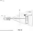
FIG. 2 is a diagram of an example configuration 200 of the front 124 of the machine 100 (e.g., when the implement 110 and the linkage 122 are extended to a “high” position, as further described herein). The perception sensor system 112 may include one or more perception sensors 126 that are positioned at different locations (e.g., on the machine 100, at the front 124 of the machine 100). For example, as shown in FIG. 2, one or more perception sensors 126 may be positioned at a first height associated with (e.g., aligned with, or nearly aligned with) a top of the operator station 104 and one or more perception sensors 126 may be positioned at a second height associated with (e.g., aligned with, or nearly aligned with) the wheels 120.
As indicated above, FIG. 2 is provided as an example. Other examples may differ from what is described in connection with FIG. 2.
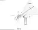
FIGS. 3A-3D are diagrams of an example implementation 300 described herein. FIGS. 3A-3B show side views of the machine 100 when the implement 110 and the linkage 122 are in different positions and fields of view of the one or more perception sensors 126 of the perception sensor system 112. FIGS. 3C-3D show top-down views of the machine 100 and fields of view of the one or more perception sensors 126 of the perception sensor system 112 with respect to determining that a target is not a destination of a projected path of the machine 100.
As shown in FIG. 3A, the implement 110 and the linkage 122 may be in a “low” position (e.g., where the implement 110 is aligned with, or nearly aligned with, the wheels 120). As part of an automatic control operation (e.g., that is associated with at least one of the machine 100 or the implement 110 and the linkage 122), the controller 114 may cause the implement 110 and the linkage 122 to be in the low position. For example, as part of the automatic control operation, the controller 114 may cause (e.g., when the machine 100 is traveling, such as in a forward direction) the implement 110 and the linkage 122 to be in the low position to enable loading and/or carrying of material, such as from a first location to a second location that is associated with a dump target (e.g., another machine, such as a dump truck). As shown in FIG. 3A, when in the low position, the implement 110 and the linkage 122 may not obstruct a field of view 302 of a first perception sensor 126 of the perception sensor system 112, and may obstruct a field of view 304 of a second perception sensor 126 of the perception sensor system 112.
As shown in FIG. 3B, the implement 110 and the linkage 122 may be in a “high” position (e.g., where the implement 110 is aligned with, or nearly aligned with, a top of the operator station 104). As part of the automatic control operation, the controller 114 may cause the implement 110 and the linkage 122 to be in the high position. For example, as part of the automatic control operation, the controller 114 may cause (e.g., when the machine 100 is traveling, such as in a forward direction) the implement 110 and the linkage 122 to be in the high position when the machine 100 is within a “dumping distance” (e.g., within a threshold distance) of the dump target (e.g., to facilitate an impending dumping of the material carried by the implement 110). As shown in FIG. 3B, when in the high position, the implement 110 and the linkage 122 may obstruct the field of view 302 of the first perception sensor 126 of the perception sensor system 112, and may not obstruct the field of view 304 of the second perception sensor 126 of the perception sensor system 112.
As shown in FIG. 3C, the machine 100 may be headed in a particular direction (e.g., east) and a target 306 (e.g., a dump target) may be within the field of view 302 of the first perception sensor 126 or the field of view 304 of the second perception sensor 126 (shown as, and referred to hereinafter as, a collective field of view 302/304). The target 306 may be associated with an identification element 308 (e.g., a fiducial, a RADAR reflector, a sonar beacon, a retroreflective marker, or another type of identification element that is detectable by the one or more perception sensors 126 of the perception sensor system 112), which identifies the target 306 (e.g., individually identifies the target 306 as distinct from other targets, or generally identifies the target 306 as a target). The identification element 308 may be connected to the target 306, or may be positioned near the target 306, and thus may be within the collective field of view 302/304. Accordingly, the controller 114 may obtain perception information, from the perception sensor system 112 (e.g., from the first perception sensor 126 and/or the second perception sensor 126) that indicates a position of the target 306. Due to a proximity of the identification element 308 to the target 306, the identification element 308 may be a positioning element that allows the perception sensor system 112 to detect the position of the target 306.
As further shown in FIG. 3C, the controller 114 may determine a projected path 310 of the machine 100. The projected path 310 may be an estimated actual path of the machine 100, which may be based on machine information obtained by the one or more machine sensors 132 of the machine sensor system 130. The machine information may indicate, for example, a steering angle of the machine 100 and/or a steering geometry of the machine 100.
In some implementations, the controller 114 may determine that the target 306 is a predicted destination of the projected path 310 (e.g., that the machine 100 is headed to the target 306). Accordingly, the controller 114 may determine a distance threshold 312 associated with the target 306 (e.g., represented as a “straight line” distance to the target 306, a travel distance to the target 306, a distance associated with a particular amount of time to travel to the target, or another distance metric). The distance threshold 312 may define, for example, a radius or boundary around the target 306. When a distance of the machine 100 to the target 306 satisfies (e.g., is less than or equal to) the distance threshold 312 (e.g., when the machine 100 crosses the radius or boundary around the target 306), the controller 114 may determine that initiation of, or performance of, an automatic control operation (e.g., that is to be performed when the machine 100 is proximate to a destination of the projected path 310) is allowable. That is, the controller 114 may allow initiation of, or performance of, the automatic control operation when the machine 100 is sufficiently near the target 306.
As shown in FIG. 3D, the machine 100 may travel across the distance threshold 312 (e.g., a distance of the machine 100 to the target 306 may satisfy the distance threshold 312), and the machine 100 may be headed in a different direction (e.g., northeast). Accordingly, the target 306 and/or the identification element 308 may not be (or may cease to be) within the collective field of view 302/304 of the perception sensor system 112. The controller 114, therefore, may determine (e.g., based on determining that the target 306 and/or the identification element 308 are not within the collective field of view 302/304 of the perception sensor system 112) that the target 306 is not, or is no longer, the predicted destination of the projected path 310 of the machine 100. Accordingly, the controller 114 may cause the automatic control operation to not be initiated, or, when already initiated, to be terminated (e.g., because the automatic control operation is to be performed when the machine 100 is proximate to a destination of the projected path 310 and because the target 306 is not, or is no longer, the predicted destination of the projected path 310).
As indicated above, FIGS. 3A-3D are provided as an example. Other examples may differ from what is described in connection with FIGS. 3A-3D.
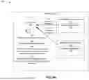
FIGS. 4A-4B are diagrams of an example implementation 400 associated with a controller determining that a target is not a predicted destination of a projected path of a machine.
As shown in FIG. 4A, and by reference number 402, the controller 114 may obtain first perception information. For example, the controller 114 may obtain the first perception information from the perception sensor system 112 (e.g., from the one or more perception sensors 126 of the perception sensor system 112). The first perception information may include respective first perception data captured by the one or more perception sensors 126. That is, each perception sensor 126, of the one or more perception sensors 126, may send first perception data that is captured by the perception sensor 126 to the controller 114 (e.g., in real time, or near real time), and therefore the controller 114 may collectively receive respective first perception data captured by the one or more perception sensors 126 as perception information. The perception information may indicate a position of the target 306 and/or a position of an identification element 308 that is associated with the target 306 (e.g., that are within a field of view of at least one perception sensor 126 of the perception sensor system 112).
As shown by reference number 404, the controller 114 may obtain first machine information. For example, the controller 114 may obtain the first machine information from the machine sensor system 130 (e.g., from the one or more machine sensors 132 of the machine sensor system 130). The first machine information may include respective first machine data captured by the one or more machine sensors 132. That is, each machine sensor 132, of the one or more machine sensors 132, may send first machine data that is captured by the machine sensor 132 to the controller 114 (e.g., in real time, or near real time), and therefore the controller 114 may collectively receive respective first machine data captured by the one or more machine sensors 132 as first machine information. The first machine information may indicate at least one of information associated with a speed of the machine 100 (e.g., information indicating the speed of the machine 100 and/or any derivative of the speed of the machine 100), information associated with a steering angle of the machine 100 (e.g., information indicating the steering angle of the machine 100 and/or any derivative of the steering angle of the machine 100), information associated with a heading of the machine (e.g., information indicating the heading of the machine 100 and/or any derivative of the heading of the machine 100), information associated with a location of the machine 100 (e.g., information indicating the location of the machine 100 and/or any derivative of the location of the machine 100), information associated with a steering geometry of the machine 100 (e.g., that indicates how the steering angle of the machine 100 corresponds to a turning radius of the machine 100, or other information), or information associated with one or more performance limits of the machine 100 (e.g., information associated with a steering velocity limit, a deceleration limit, an acceleration limit, and/or other performance limits of the machine 100), along with other examples.
As shown by reference number 406, the controller 114 may determine that the target 306 is a predicted destination of a projected path 310 of the machine 100, such as based on the first perception information and, optionally, the first machine information. The controller 114 may determine that the target 306 is the predicted destination of the projected path 310 of the machine 100 at a first instant in time (e.g., that occurs before a second instant in time, as further described herein). Thus, the controller 114 may obtain the first perception information and/or the first machine information (e.g., as described herein in relation to reference numbers 402 and 404) before the first instant in time, to enable determining that the target 306 is the predicted destination of the projected path 310 of the machine 100 at the first instant in time.
As an example, to determine that the target 306 is the predicted destination of the projected path 310 of the machine 100 at the first instant in time, the controller 114 may determine, based on the first perception information, such as by processing (e.g., parsing and/or reading, along with other examples) the first perception information, that the target 306 and/or that the identification element 308 associated with the target 306 are within a field of view of at least one perception sensor 126 of the perception sensor system 112. The controller 114 may thereby determine that the target is the predicted destination of the projected path 310 of the machine 100 at the first instant in time.
As another example, the controller 114 may determine, based on the first perception information, such as by processing (e.g., parsing and/or reading, along with other examples) the first perception information, a position of the target 306. Additionally, the controller 114 may determine, based on the first machine information, the projected path 310 of the machine at the first instant in time. To determine the projected path 310 at the first instant in time, the controller 114 may determine, such as by processing (e.g., parsing and/or reading, along with other examples) the first machine information, information associated with a steering angle of the machine 100 and information associated with a steering geometry of the machine 100. The controller 114 may thereby determine a projected path radius of the machine 100 (e.g., with the steering angle of the machine 100 held constant), and may determine, based on the projected path radius of the machine 100, the projected path 310 of the machine 100 at the first instant in time. The projected path 310 of the machine 100 (or at least a portion of the projected path 310 of the machine 100) at the first instant in time may therefore be, in some implementations, a circle (or a portion of a circle) defined by the projected path radius.
Accordingly, the controller 114 may determine, based on the projected path 310 of the machine 100 at the first instant in time and the position of the target 306, that the target 306 is the predicted destination of the projected path 310 of the machine 100 at the first instant in time. For example, the controller 114 may determine that the projected path 310 at the first instant in time is likely to lead to the position of the target 306. As another example, the controller 114 may determine potential paths of the machine 100 to the target 306 (e.g., based on the first perception information and/or the first state information), such as potential viable paths of the machine 100 to the target 306, and may determine (e.g., using a cost function, or another analysis technique) that the projected path 310 at the first instant in time is associated with (e.g., is similar to) a particular potential path. The controller 114 may therefore determine that the target 306 is the predicted destination of the projected path 310 of the machine 100 at the first instant in time.
As shown by reference number 408, the controller 114 may determine that a distance from the machine 100 to the target 306 satisfies (e.g., is less than or equal to) a distance threshold 312 associated with the target 306 (e.g., based on determining that the target 306 is the predicted destination of the projected path 310 of the machine 100 at the first instant in time). As described herein in relation to FIGS. 3C-3D, the distance threshold 312 may define a radius or boundary around the target 306, and when a distance of the machine 100 to the target 306 (e.g., as the predicted destination of the projected path 310) satisfies the distance threshold 312 (e.g., when the machine 100 crosses the radius or boundary around the target 306), the controller 114 may determine that initiation of, or performance of, an automatic control operation (e.g., that is to be performed proximate to a destination of the projected path 310) is allowable.
The controller 114 may determine the distance from the machine 100 to the target 306 at an instant in time that occurs at, or after, the first instant in time and before a second instant in time, further described herein. For example, the controller 114 may determine, based on the first perception information or other perception information (e.g., that is obtained from the perception sensor system 112 after the first instant in time and before the second instant in time), such as by processing (e.g., parsing and/or reading, along with other examples) the perception information or the other perception information, the distance from the machine 100 to the target 306 that occurs at the instant in time. Accordingly, the controller 114 may determine that the distance from the machine 100 at the instant in time is less than or equal to the distance threshold 312, and that the distance threshold 312 is therefore satisfied. The other perception information may also be referred to as third perception information herein.
As shown in FIG. 4B, and by reference number 410, the controller 114 may obtain second perception information (e.g., based on determining that the target 306 is the predicted destination of the projected path 310 of the machine 100 at the first instant in time and/or determining that the distance from the machine 100 to the target 306 satisfies the distance threshold 312). The controller 114 may obtain the second perception information in a similar manner as that described herein in relation to FIG. 4A and reference number 402. For example, the controller 114 may obtain the second perception information from the perception sensor system 112 (e.g., from the one or more perception sensors 126 of the perception sensor system 112). The controller 114 may obtain the second perception information after obtaining the first perception information, after determining that the target 306 is the predicted destination of the projected path 310 of the machine 100 at the first instant in time, and/or after determining that the distance from the machine 100 to the target 306 satisfies the distance threshold 312.
In some implementations, such as shown in FIG. 3D, a heading of the machine 100 may change (e.g., as compared to a heading of the machine 100 when the controller 114 obtained the first perception information). Accordingly, the target 306 and/or the identification element 308 may not be (or may cease to be) within a field of view of any perception sensor 126 of the perception sensor system 112. Therefore, the second perception information may not indicate a position of the target 306 and/or a position of the identification element 308 that is associated with the target 306.
As shown by reference number 412, the controller 114 may obtain second machine information (e.g., based on determining that the target 306 is the predicted destination of the projected path 310 of the machine 100 at the first instant in time and/or determining that the distance from the machine 100 to the target 306 satisfies the distance threshold 312). The controller 114 may obtain the second machine information in a similar manner as that described herein in relation to FIG. 4A and reference number 404. For example, the controller 114 may obtain the second machine information from the machine sensor system 130 (e.g., from the one or more machine sensors 132 of the machine sensor system 130). The second machine information may indicate similar, but more recent, information as the first machine information.
As shown by reference number 414, the controller 114 may determine that the target 306 is not, or is no longer, the predicted destination of the projected path 310 of the machine 100, such as based on the second perception information and, optionally, the second machine information. The controller 114 may determine that the target 306 is not, or is no longer, the predicted destination of the projected path 310 of the machine 100 at the second instant in time (e.g., that occurs after the first instant in time described herein). Thus, the controller 114 may obtain the second perception information and/or the second machine information (e.g., as described herein in relation to reference numbers 410 and 412) before the second instant in time to enable determining that the target 306 is not, or is no longer, the predicted destination of the projected path 310 of the machine 100 at the second instant in time.
As an example, to determine that the target 306 is not, or is no longer, the predicted destination of the projected path 310 of the machine 100 at the second instant in time, the controller 114 may determine, such as by processing (e.g., parsing and/or reading, along with other examples) the second perception information, that the target 306 and/or that the identification element 308 associated with the target 306 are not within, or are no longer within, a field of view of at least one perception sensor 126 of the perception sensor system 112. Thus, the controller 114 may determine that the target is not, or is no longer, the predicted destination of the projected path 310 of the machine 100 at the second instant in time.
As another example, the controller 114 may determine, such as by processing (e.g., parsing and/or reading, along with other examples) the first perception information and/or the second perception information, the position of the target 306. Additionally, the controller 114 may determine, based on the second machine information, the projected path 310 of the machine at the second instant in time. To determine the projected path 310 at the second instant in time, the controller 114 may determine, such as by processing (e.g., parsing and/or reading, along with other examples) the second machine information, information associated with a steering angle (e.g., an updated steering angle) of the machine 100 and information associated with the steering geometry of the machine 100. Accordingly, the controller 114 may determine, based on the information associated with the steering angle of the machine 100 and the information associated with the steering geometry of the machine 100, an updated projected path radius of the machine 100 (e.g., with the steering angle of the machine 100 held constant), and may determine, based on the updated projected path radius of the machine 100, the projected path 310 of the machine 100 at the second instant in time. The projected path 310 of the machine 100 (or at least a portion of the projected path 310 of the machine 100) at the second instant in time may therefore be a circle (or a portion of a circle) defined by the projected path radius.
Accordingly, the controller 114 may determine, based on the projected path 310 of the machine 100 at the second instant in time and the position of the target 306, that the target 306 is not, or is no longer, the predicted destination of the projected path 310 of the machine 100 at the second instant in time. For example, the controller 114 may determine that the projected path 310 at the second instant in time is not likely to lead to the position of the target 306. As another example, the controller 114 may determine potential paths of the machine 100 to the target 306 (e.g., based on the second perception information and/or the second state information), such as potential viable paths of the machine 100 to the target 306, and may determine (e.g., using a cost function, or another analysis technique) that the projected path 310 at the second instant in time is not associated with (e.g., is not similar to) any potential path. Additionally, when the projected path 310 was previously associated with a particular potential path (e.g., at the first instant in time), the controller 114 may determine that the projected path 310 at the second instant in time is not associated with (e.g., is not similar to) the particular potential path, such as due to a change of cost characteristics of the particular potential path at the second instant in time (e.g., an increased cost due to a sharp turn is needed to reach the position of the target 306, an increased cost due to an unstable driving maneuver is needed to reach the position of the target 306, or an increased cost due to extreme braking performance or extreme steering rate is needed to reach the position of the target 306, along with other examples) The controller 114 may therefore determine that the target 306 is not, or is no longer, the predicted destination of the projected path 310 of the machine 100 at the second instant in time.
As shown by reference number 416, the controller 114 may cause an automatic control operation to not be initiated, or, when already initiated, to be terminated (e.g., based on determining that the target 306 is not, or is no longer, the predicted destination of the projected path 310 of the machine 100, such as at the second instant in time). The automatic control operation may be associated with a destination (e.g., an actual destination) of the projected path 310. For example, the automatic control operation may be configured to be performed when the machine 100 is proximate to the destination of the projected path 310. The automatic control operation may also be associated with at least one of the machine 100, or the implement 110 and the linkage 122. For example, the automatic control operation may cause the machine 100 to travel to or from the target 306 (e.g., as the predicted destination of the projected path 310 of the machine 100) and/or may cause the implement 110 and the linkage 122 to move to particular positions (e.g., based on a proximity of the machine 100 to the target 306). Thus, the controller 114 may cause the automatic control operation to not be initiated, or, when already initiated, to be terminated (e.g., because the automatic control operation is to be performed when the machine 100 is proximate to the destination of the projected path 310 and because the target 306 is not, or is no longer, the predicted destination of the projected path 310).
As indicated above, FIGS. 4A-4B are provided as an example. Other examples may differ from what is described in connection with FIGS. 4A-4B.
FIG. 5 is a diagram of example components of a device 500 associated with determining that a target is not a predicted destination of a projected path of a machine. The device 500 may correspond to the perception sensor system 112, the controller 114, the plurality of perception sensors 126, the machine sensor system 130, and/or the plurality of machine sensors 132. The perception sensor system 112, the controller 114, the plurality of perception sensors 126, the machine sensor system 130, and/or the plurality of machine sensors 132 may include one or more devices 500 and/or one or more components of the device 500. As shown in FIG. 5, the device 500 may include a bus 510, a processor 520, a memory 530, an input component 540, an output component 550, and/or a communication component 560.
The bus 510 may include one or more components that enable wired and/or wireless communication among the components of the device 500. The bus 510 may couple together two or more components of FIG. 5, such as via operative coupling, communicative coupling, electronic coupling, and/or electric coupling. For example, the bus 510 may include an electrical connection (e.g., a wire, a trace, and/or a lead) and/or a wireless bus. The processor 520 may include a central processing unit, a graphics processing unit, a microprocessor, a controller, a microcontroller, a digital signal processor, a field-programmable gate array, an application-specific integrated circuit, and/or another type of processing component. The processor 520 may be implemented in hardware, firmware, or a combination of hardware and software. The processor 520 may include one or more processors capable of being programmed to perform one or more operations or processes described elsewhere herein.
The memory 530 may include volatile and/or nonvolatile memory. For example, the memory 530 may include random access memory (RAM), read only memory (ROM), a hard disk drive, and/or another type of memory (e.g., a flash memory, a magnetic memory, and/or an optical memory). The memory 530 may include internal memory (e.g., RAM, ROM, or a hard disk drive) and/or removable memory (e.g., removable via a universal serial bus connection). The memory 530 may be a non-transitory computer-readable medium. The memory 530 may store information, one or more instructions, and/or software (e.g., one or more software applications) related to the operation of the device 500. The memory 530 may include one or more memories that are coupled (e.g., communicatively coupled) to one or more processors (e.g., processor 520), such as via the bus 510. Communicative coupling between a processor 520 and a memory 530 may enable the processor 520 to read and/or process information stored in the memory 530 and/or to store information in the memory 530.
The input component 540 may enable the device 500 to receive input, such as user input and/or sensed input. For example, the input component 540 may include a touch screen, a keyboard, a keypad, a mouse, a button, a microphone, a switch, a sensor, a global positioning system sensor, a global navigation satellite system sensor, an accelerometer, a gyroscope, and/or an actuator. The output component 550 may enable the device 500 to provide output, such as via a display, a speaker, and/or a light-emitting diode. The communication component 560 may enable the device 500 to communicate with other devices via a wired connection and/or a wireless connection. For example, the communication component 560 may include a receiver, a transmitter, a transceiver, a modem, a network interface card, and/or an antenna.
The device 500 may perform one or more operations or processes described herein. For example, a non-transitory computer-readable medium (e.g., memory 530) may store a set of instructions (e.g., one or more instructions or code) for execution by the processor 520. The processor 520 may execute the set of instructions to perform one or more operations or processes described herein. Execution of the set of instructions, by one or more processors 520, causes the one or more processors 520 and/or the device 500 to perform one or more operations or processes described herein. Hardwired circuitry may be used instead of or in combination with the instructions to perform one or more operations or processes described herein. Additionally, or alternatively, the processor 520 may be configured to perform one or more operations or processes described herein. Thus, implementations described herein are not limited to any specific combination of hardware circuitry and software.
The number and arrangement of components shown in FIG. 5 are provided as an example. The device 500 may include additional components, fewer components, different components, or differently arranged components than those shown in FIG. 5. A set of components (e.g., one or more components) of the device 500 may perform one or more functions described as being performed by another set of components of the device 500.
Industrial Applicability
Implementations described herein may be used with any machine that includes a controller and a perception sensor system that includes one or more perception sensors, such as any machine that utilizes an implement and linkage, such as a wheel loader that includes an implement and linkage to load, carry, and dump material (e.g., into a dump target).
A machine can include one or more perception sensors to detect a position of a target (e.g., a dump target, such as a dump truck), such as to facilitate an automatic control operation (e.g., that controls a movement of the machine or an operation of an implement and a linkage of the machine, such as in relation to the target). For example, the one or more perception sensors can capture and pass perception information that indicates a position of the target to a controller of the machine, and the controller thereby identifies the target as a destination of a projected path of the machine. Accordingly, the controller causes an automatic control operation to be performed with respect to the target when the machine travels sufficiently near the target.
However, in many cases, the target is not an intended destination of the projected path of the machine. For example, an operator of the machine may direct the machine to travel toward the target, but the operator may intend to steer the machine around the target as the machine approaches the target, such as to allow the machine to travel to the intended destination (e.g., another target). Consequently, because the controller incorrectly identified the target as the destination of the projected path of the machine, the controller causes the automatic control operation to be performed when the machine travels sufficiently near the target, even though the target is not the intended destination of the machine.
This can affect a performance of the machine (e.g., due to unnecessary performance of the automatic control operation). For example, when the automatic control operation includes lifting the implement (e.g., that holds material for eventual dumping) and the linkage to a high position, the center of the gravity of the machine is elevated. This can reduce a stability and a control of the machine, which can lead to spillage of the material carried by the machine. Further, unnecessary lifting of the implement and the linkage, particularly when carrying a heavy load of material, can increase wear and tear on the implement and on the linkage, which can impact a performance of, as well as reduce an operable life of, the implement and the linkage, and the machine.
In some implementations, a controller of a machine obtains first perception information (e.g., that indicates a position of a target) from a perception sensor system and first machine information from a machine sensor system. The controller determines (e.g., based on the first perception information, and, optionally, the first machine information) that the target is a predicted destination of a projected path of the machine at a first instant in time. The controller then obtains second perception information from the perception sensor system and second machine information from the machine sensor system. Because a heading of the machine may have changed after the first instant in time, the target (and/or an identification element associated with the target) may not be within a field of view of the perception sensor system when the second perception information is captured by the perception sensor system, and thus (e.g., because the second perception information does not indicate that the target and/or the identification are within the field of view of the perception sensor system) the controller may determine that the target is not, or is no longer, the predicted destination of the projected path of the machine at a second instant in time. Accordingly, the controller causes, based on determining that the target is not the predicted destination of the projected path at the second instant in time, an automatic control operation to not be initiated, or, when already initiated, to be terminated (e.g., when the machine travels sufficiently near the target).
In this way, the controller of the machine is able to determine that a target is not a predicted destination of a projected path of a machine, such as after previously determining that that the target is the predicted destination of the projected path of the machine. Accordingly, the controller prevents, or at least reduces a likelihood of, an automatic control operation being erroneously performed (or fully performed) by the machine when in proximity of the target (e.g., that is not, or is not any longer, the predicted destination of the machine). Thus, unnecessary lifting of an implement (e.g., that holds material for eventual dumping) and a linkage of the machine is reduced, such as when the automatic control operation includes lifting the implement and the linkage to a high position. Therefore, a stability and a control of the machine are improved (e.g., by not unnecessarily elevating a center of gravity of the machine), which can reduce a likelihood of spillage of the material carried by the implement of machine. Additionally, wear and tear on the implement and the linkage is reduced, which improves a performance of, as well as increases an operable life of, the implement and the linkage, and the machine.
Claims
What is claimed is:1. A machine comprising:
an implement and a linkage;
a perception sensor system that includes one or more perception sensors;
a machine sensor system that includes one or more machine sensors; and
a controller configured to:
obtain first perception information from the perception sensor system;
determine, based on the first perception information, that a target is a predicted destination of a projected path of the machine at a first instant in time;
obtain, after determining that the target is the predicted destination of the projected path of the machine at the first instant in time, second perception information from the perception sensor system; and
determine, based on the second perception information, that the target is not the predicted destination of the projected path of the machine at a second instant in time.
2. The machine of claim 1, wherein the controller is further configured to:
cause, based on determining that the target is not the predicted destination of the projected path at the second instant in time, an automatic control operation associated with the target and at least one of the machine, or the implement and the linkage, to not be initiated, or, when already initiated, to be terminated.
3. The machine of claim 1, wherein the controller, to determine that the target is the predicted destination of the projected path of the machine at the first instant in time, is configured to:
determine, based on the first perception information, that an identification element associated with the target is within a field of view of at least one perception sensor, of the one or more perception sensors, of the perception sensor system; and
determine, based on determining that the identification element is within the field of view of the at least one perception sensor, that the target is the predicted destination of the projected path of the machine at the first instant in time.
4. The machine of claim 1, wherein the controller, to determine that the target is not the predicted destination of the projected path of the machine at the second instant in time, is configured to:
determine, based on the second perception information, that an identification element associated with the target is not within a field of view of at least one perception sensor, of the one or more perception sensors, of the perception sensor system; and
determine, based on determining that the identification element is not within the field of view of the at least one perception sensor, that the target is not the predicted destination of the projected path of the machine at the second instant in time.
5. The machine of claim 1, wherein the controller, to determine that the target is the predicted destination of the projected path of the machine at the first instant in time, is configured to:
obtain machine information from the machine sensor system;
determine, based on the machine information, the projected path of the machine at the first instant in time;
determine, based on the first perception information, a position of the target; and
determine, based on the projected path of the machine at the first instant in time and the position of the target, that the target is the predicted destination of the projected path of the machine at the first instant in time.
6. The machine of claim 1, wherein the controller, to determine that the target is not the predicted destination of the projected path of the machine at the second instant in time, is configured to:
obtain machine information from the machine sensor system;
determine, based on the machine information, the projected path of the machine at the second instant in time;
determine, based on at least one of the first perception information or the second perception information, a position of the target; and
determine, based on the projected path of the machine at the second instant in time and the position of the target, that the target is not the predicted destination of the projected path of the machine at the second instant in time.
7. The machine of claim 1, wherein the controller, to obtain the second perception information from the perception sensor system, is configured to:
determine, based on at least one of the first perception information or third perception information obtained from the perception sensor system, a distance from the machine to the target at an instant in time that occurs at, or after, the first instant in time and before the second instant in time;
determine that the distance from the machine to the target is less than or equal to a distance threshold; and
obtain the second perception information based on determining that the distance from the machine to the target is less than or equal to the distance threshold.
8. A controller of a machine, comprising:
one or more memories; and
one or more processors, coupled to the one or more memories, configured to:
determine, based on first perception information obtained from a perception sensor system of the machine, that a target is a predicted destination of a projected path of the machine at a first instant in time;
determine, based on determining that the target is the predicted destination of the projected path of the machine at the first instant in time, that a distance from the machine to the target satisfies a distance threshold; and
determine, based on determining that the distance from the machine to the target satisfies the distance threshold, and based on at least one of the first perception information or second perception information obtained from the perception sensor system, that the target is not the predicted destination of the projected path of the machine at a second instant in time.
9. The controller of claim 8, wherein the one or more processors are further configured to:
cause, based on determining that the target is not the predicted destination of the projected path at the second instant in time, an automatic control operation associated with the target to not be initiated, or, when already initiated, to be terminated.
10. The controller of claim 8, wherein the one or more processors, to determine that the target is the predicted destination of the projected path of the machine at the first instant in time, are configured to:
determine, based on the first perception information, that an identification element associated with the target is within a field of view of the perception sensor system; and
determine, based on determining that the identification element is within the field of view of the perception sensor system, that the target is the predicted destination of the projected path of the machine at the first instant in time.
11. The controller of claim 8, wherein the one or more processors, to determine that the target is not the predicted destination of the projected path of the machine at the second instant in time, are configured to:
determine, based on the second perception information, that an identification element associated with the target is not within a field of view of the perception sensor system; and
determine, based on determining that the identification element is not within the field of view of the perception sensor system, that the target is not the predicted destination of the projected path of the machine at the second instant in time.
12. The controller of claim 8, wherein the one or more processors, to determine that the target is the predicted destination of the projected path of the machine at the first instant in time, are configured to:
determine, based on machine information obtained from a machine sensor system of the machine, the projected path of the machine at the first instant in time;
determine, based on the first perception information, a position of the target; and
determine, based on the projected path of the machine at the first instant in time and the position of the target, that the target is the predicted destination of the projected path of the machine at the first instant in time.
13. The controller of claim 8, wherein the one or more processors, to determine that the target is not the predicted destination of the projected path of the machine at the second instant in time, are configured to:
determine, based on machine information obtained from a machine sensor system of the machine, the projected path of the machine at the second instant in time;
determine, based on at least one of the first perception information or the second perception information, a position of the target; and
determine, based on the projected path of the machine at the second instant in time and the position of the target, that the target is not the predicted destination of the projected path of the machine at the second instant in time.
14. The controller of claim 8, wherein the one or more processors, to determine that the distance from the machine to the target satisfies the distance threshold, are configured to:
determine, based on at least one of the first perception information or third perception information obtained from the perception sensor system, the distance from the machine to the target at an instant in time that occurs at, or after, the first instant in time and before the second instant in time; and
determine that the distance from the machine to the target is less than or equal to the distance threshold.
15. A method, comprising:
determining, by a controller of a machine, that a distance from the machine to a target, which is a predicted destination of a projected path of the machine at a first instant in time, satisfies a distance threshold; and
determining, by the controller, based on determining that the distance from the machine to the target satisfies the distance threshold, and based on perception information obtained from a perception sensor system of the machine, that the target is not the predicted destination of the projected path of the machine at a second instant in time.
16. The method of claim 15, further comprising:
causing, based on determining that the target is not the predicted destination of the projected path at the second instant in time, an automatic control operation associated with the target to not be initiated, or, when already initiated, to be terminated.
17. The method of claim 15, wherein determining that the target is not the predicted destination of the projected path of the machine at the second instant in time comprises:
determining, based on the perception information, that an identification element associated with the target is not within a field of view of the perception sensor system; and
determining, based on determining that the identification element is not within the field of view of the perception sensor system, that the target is not the predicted destination of the projected path of the machine at the second instant in time.
18. The method of claim 15, wherein determining that the target is not the predicted destination of the projected path of the machine at the second instant in time comprises:
determining, based on machine information obtained from a machine sensor system of the machine, the projected path of the machine at the second instant in time;
determining, based on the perception information, a position of the target; and
determining, based on the projected path of the machine at the second instant in time and the position of the target, that the target is not the predicted destination of the projected path of the machine at the second instant in time.
19. The method of claim 15, wherein determining that that the distance from the machine to the target satisfies the distance threshold comprises:
determining the distance from the machine to the target at an instant in time that occurs at, or after, the first instant in time and before the second instant in time.
20. The method of claim 15, further comprising:
determining that the target is the predicted destination of the projected path of the machine at the first instant in time based on at least one of:
determining that an identification element associated with the target is within a field of view of the perception sensor system, or
determining the projected path of the machine at the first instant in time and a position of the target.
Images & Drawings included:


Sources:
- United States Patent and Trademark Office - verify current appl. status at the USPTO↗
Recent applications in this class:
- » 20260015816 2026-01-15
MACHINE GUIDANCE SYSTEM FOR TERRAIN DETECTION AND/OR AUTONOMOUS EXCAVATION USING A CONSTRUCTION ASSET - » 20250188703 2025-06-12
WORK MACHINE AND METHOD OF CONTROLLING WORK MACHINE - » 20250027290 2025-01-23
CONTROL DEVICE, LOADING MACHINE, AND CONTROL METHOD TO DETERMINE A TARGET AZIMUTH DIRECTION - » 20240392531 2024-11-28
Wheel Loader - » 20240279901 2024-08-22
SKID STEER LOADER POWER BOOST - » 20240247460 2024-07-25
CONTROL SYSTEM, CONTROL METHOD, AND WORK MACHINE - » 20240209590 2024-06-27
SHOVEL - » 20240175235 2024-05-30
Work Machine Control Method, Work Machine Control Program, Work Machine Control System, And Work Machine - » 20240011241 2024-01-11
SHOVEL AND CONTROL DEVICE FOR SHOVEL - » 20240011240 2024-01-11
ENHANCED TRACTOR LOADER WITH VARIABLE SPEED CONTROL FOR ELECTRIC ACTUATION AND AUTOMATIC BUCKET LEVELING
Recent applications for this Assignee:
- » 20260146557 2026-05-28
AFTERCOOLER WITH TUBE AND FIN DESIGN - » 20260146520 2026-05-28
ENGINE LOAD MANAGEMENT IN A HYDRAULIC FRACTURING SYSTEM USING A SLIP DEVICE - » 20260146519 2026-05-28
TORQUE CONTROL WITH A SLIP DEVICE FOR PRESSURE TESTING A HYDRAULIC FRACTURING SYSTEM - » 20260146415 2026-05-28
VALIDATION OF PERCEPTION INFORMATION OBTAINED BY A PERCEPTION SENSOR SYSTEM THAT INCLUDES A PLURALITY OF SENSORS - » 20260146410 2026-05-28
DETERMINING THAT A TARGET IS A DESTINATION OF A PROJECTED PATH OF A MACHINE - » 20260146405 2026-05-28
MACHINE WITH A PERCEPTION SENSOR SYSTEM THAT INCLUDES MULTIPLE SETS OF ONE OR MORE SENSORS - » 20260142462 2026-05-21
ENERGY OPTIMIZATION FOR LOAD PEAK SHAVING WITH MICROGRID CONTROL SYSTEMS - » 20260139711 2026-05-21
CONNECTOR FOR DYNAMIC ENERGY TRANSFER SYSTEM - » 20260135391 2026-05-14
OPTIMIZED RENEWABLE FUEL PRODUCTION USING A MICROGRID CONTROLLER - » 20260135249 2026-05-14
FIRE CONFINING COOLING DUCT DESIGN FOR BATTERY RACKS WITH INTEGRATED FIREPROOF STRUCTURE