FLUSH TOILET
US20260146429A1
2026-05-28
19/379,639
2025-11-04
Smart Summary: A flush toilet uses a special design to help remove waste efficiently. It has a bowl and a pipe that carries waste away, which includes an upward section. Water is directed through a jet spout to create a strong flush that pushes waste into the pipe. The design includes a narrower section in the upper part of the pipe to help control the flow of water. This setup ensures that the toilet flushes effectively while using less water. 🚀 TL;DR
Abstract:
A flush toilet is a siphon jet flush toilet that includes a bowl, a discharge trap conduit that includes an ascending conduit extending upward, a jet spout port configured to spout flush water toward an inlet of the discharge trap conduit, and a jet water conduit configured to guide flush water to the jet spout port, in which in a flow channel cross-section of the ascending conduit of the discharge trap conduit, a narrowed portion that narrows a flow channel in which the flush water flows is provided in an upper-side flow channel located above a center line of the discharge trap conduit in an up-down direction, and a flow channel cross-sectional area of the upper-side flow channel is smaller than a flow channel cross-sectional area of a lower-side flow channel located below the center line.
Inventors:
- Masaaki MOMOE 19 🇯🇵 Kitakyushu-shi, Japan
- Taizo SHIMADA 2 🇯🇵 Kitakyushu-shi, Japan
- Daisuke NAKAMURA 2 🇯🇵 Kitakyushu-shi, Japan
- Takuro MORIYAMA 2 🇯🇵 Kitakyushu-shi, Japan
Assignee:
- TOTO LTD. 167 🇯🇵 KITAKYUSHU-SHI, Japan
Applicant:
Interested in similar patents?
Get notified when new applications in this technology area are published.
Classification:
E03D5/01 » CPC main
Special constructions of flushing devices e.g. closed flushing system , using flushing pumps
Description
This application claims benefit of priority to Japanese Patent Application No. 2024-204168, filed on Nov. 22, 2024, the entire content of which is incorporated herein by reference.
BACKGROUND OF THE INVENTION
Field of the Invention
The present invention relates to a flush toilet, and more particularly, to a siphon jet flush toilet.
Description of the Related Art
There is conventionally known a siphon jet flush toilet provided with a jet spout port at a position facing an inlet of a discharge trap conduit. Such a flush toilet is configured to fill the discharge trap conduit with flush water spouted from a jet spout port promptly to cause a siphon action and wash away waste. However, an amount of flush water spouted from the jet spout port tends to be reduced in accordance with a recent request for water saving, and it is desired to efficiently discharge the waste with the flush water spouted from the jet spout port.
Under the circumstances, in a siphon jet flush toilet disclosed in Japanese Patent Laid-Open No. 2013-72238, a guide portion for guiding, toward a center of a flow channel cross-section, flush water flowing backward is formed in an ascending conduit of a discharge trap conduit. Thus, the flush water attempting to flow backward in the ascending conduit of the discharge trap conduit is guided toward the center of the flow channel cross-section, so that waste is washed away with the flush water spouted from the jet spout port.
In a siphon jet flush toilet disclosed in Japanese Patent Laid-Open No. 2018-3262, a curved surface that inclines downward is formed in a bottom surface of a bowl which is continuous to a jet spout port. Thus, the flush water spouted from a jet spout port flows into a discharge trap conduit promptly to cause a siphon action.
Furthermore, in a siphon jet flush toilet disclosed in Japanese Patent Laid-Open No. 2018-3263, a downstream side of a jet water conduit is formed to gradually spread out toward the jet spout port. Thus, the flush water is spouted from the jet spout port across a wide area to wash away waste.
However, in the flush toilets disclosed in Japanese Patent Laid-Open Nos. 2013-72238, 2018-3262, and 2018-3263, when an amount of flush water spouted from the jet spout port is further reduced, waste (in particular, floating waste) cannot be sufficiently discharged.
For example, FIG. 7 illustrates, by numerical analysis, a state in which the flush water spouted from the jet spout port flows in the discharge trap conduit in a conventional flush toilet. In this numerical analysis result, the directions of flows of the flush water are shown by arrows, long arrows indicate regions where the flow velocity of the flush water is high and water force is strong, and short arrows indicate regions where the flow velocity of the flush water is low and water force is weak.
As illustrated in FIG. 7, in the conventional flush toilet, a main stream of the flush water spouted from the jet spout port collides with the ascending conduit of the discharge trap conduit, and then, rises and flows in a region (region A in FIG. 7) in the vicinity of the bottom surface of the ascending conduit. However, in a region (region B in FIG. 7) in the vicinity of an upper surface of the ascending conduit which is away from the main stream of this flush water, the flush water is retained without being able to rise along the ascending conduit, generating a turbulent flow. That is, in the region (region B in FIG. 7) in the vicinity of the upper surface of the ascending conduit, the waste (in particular, floating waste) is likely to be retained. Therefore, in the conventional flush toilet, a large flow rate of flush water is spouted from the jet spout port for a long period of time, so that waste retained in the discharge trap conduit is discharged.
However, when an amount of flush water spouted from the jet spout port is further reduced in accordance with a recent request for water saving, the waste (in particular, floating waste) is retained in the region (region B in FIG. 7) in the vicinity of the upper surface of the ascending conduit, which makes it impossible to sufficiently discharge the waste.
Under the circumstances, the present invention has been made to solve the above-described conventional problem, and has an object to provide a flush toilet that can sufficiently discharge waste (in particular, floating waste) even if an amount of flush water is further saved.
SUMMARY OF THE INVENTION
In order to attain the above-described object, the present invention is to provide a siphon jet flush toilet that includes a bowl that includes a waste receiving surface configured to receive waste, and a rim formed above the waste receiving surface, a discharge trap conduit that includes an ascending conduit provided in a lower portion of the bowl and extending upward, a descending conduit extending downward from the ascending conduit, and a top portion located between the descending conduit and the ascending conduit, a jet spout port provided in the lower portion of the bowl and configured to spout flush water toward an inlet of the discharge trap conduit, and a jet water conduit configured to guide flush water to the jet spout port, in which in a flow channel cross-section of the ascending conduit of the discharge trap conduit, a narrowed portion that narrows a flow channel in which the flush water flows is provided in an upper-side flow channel located above a center line of the discharge trap conduit in an up-down direction, and a flow channel cross-sectional area of the upper-side flow channel is smaller than a flow channel cross-sectional area of a lower-side flow channel located below the center line.
In the present invention configured as described above, in the flow channel cross-section of the ascending conduit of the discharge trap conduit, the narrowed portion that narrows the flow channel in which the flush water flows is provided in the upper-side flow channel located above the center line of the discharge trap conduit in the up-down direction, and the flow channel cross-sectional area of the upper-side flow channel is smaller than the flow channel cross-sectional area of the lower-side flow channel located below the center line, thereby making it possible to reduce retention of the flush water in the discharge trap conduit and efficiently transport the waste in the discharge trap conduit. Therefore, the waste (in particular, floating waste) can be sufficiently discharged even if an amount of flush water is further saved.
In the present invention, it is preferable that the narrowed portion is provided at least on an upstream side of the ascending conduit.
In the present invention configured as described above, the narrowed portion is provided at least on the upstream side of the ascending conduit, thereby making it possible to further reduce retention of the flush water in the discharge trap conduit and efficiently transport the waste in the discharge trap conduit.
In the present invention, it is preferable that the narrowed portion is provided to extend from an upstream end portion to a downstream end portion of the ascending conduit.
In the present invention configured as described above, the narrowed portion is provided to extend from the upstream end portion to the downstream end portion of the ascending conduit, thereby making it possible to further reduce retention of the flush water in the discharge trap conduit and efficiently transport the waste in the discharge trap conduit.
In the present invention, it is preferable that in a flow channel cross-section, the narrowed portion is provided in a region outside a predetermined curvature radius around a center point through which a main stream of the flush water spouted from the jet spout port passes.
In the present invention configured as described above, in the flow channel cross-section, the narrowed portion is provided in the region outside the predetermined curvature radius around the center point through which the main stream of the flush water spouted from the jet spout port passes, thereby making it possible to reduce the region in which the flush water is retained without inhibiting transport of the waste in the discharge trap conduit.
In addition, in the present invention, it is preferable that an upstream end portion of the ascending conduit of the discharge trap conduit is formed so that the flow channel cross-sectional area of the upper-side flow channel is gradually reduced toward a downstream side.
In the present invention configured as described above, the upstream end portion of the ascending conduit of the discharge trap conduit is formed so that the flow channel cross-sectional area of the upper-side flow channel is gradually reduced toward the downstream side, thereby making it possible to smoothly guide the flush water to the narrowed portion and efficiently transport the waste in the discharge trap conduit.
In the present invention, it is preferable that a position where the flow channel cross-sectional area of the upper-side flow channel is minimized is located on a downstream side with respect to a collision position where a main stream of the flush water spouted from the jet spout port collides with the ascending conduit.
In the present invention configured as described above, a position where the flow channel cross-sectional area of the upper-side flow channel is minimized is located on the downstream side with respect to the collision position where the main stream of the flush water spouted from the jet spout port collides with the ascending conduit, thereby making it possible to reduce a region in which the flush water on the downstream side with respect to the collision position is most likely to be retained.
In addition, in the present invention, it is preferable that an upper end portion of the top portion of the discharge trap conduit is located on a downstream side with respect to a lower end portion of the top portion of the discharge trap conduit.
In the present invention configured as described above, the upper end portion of the top portion of the discharge trap conduit is located on the downstream side with respect to the lower end portion of the top portion of the discharge trap conduit, thereby making it possible to provide the narrowed portion to extend to the vicinity of the top portion.
According to the flush toilet of the present invention, the waste (in particular, floating waste) can be sufficiently discharged even if an amount of flush water is further saved.
BRIEF DESCRIPTION OF THE DRAWINGS
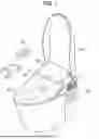
FIG. 1 is a perspective view of a flush toilet according to an embodiment of the present invention;
FIG. 2 is an overall configuration diagram of the flush toilet according to the embodiment of the present invention;
FIG. 3 is a block diagram illustrating a configuration related to a controller of the flush toilet according to the embodiment of the present invention;
FIG. 4 is a side sectional view of the flush toilet according to the embodiment of the present invention;
FIG. 5A is a sectional view taken along line A-A in FIG. 4;
FIG. 5B is a sectional view taken along line B-B in FIG. 4;
FIG. 5C is a sectional view taken along line C-C in FIG. 4;
FIG. 6 is a diagram illustrating a result obtained by numerically analyzing distribution of flow velocities of flush water flowing in a discharge trap conduit, the flush water being spouted from a jet spout port, in the flush toilet according to the embodiment of the present invention; and
FIG. 7 is a diagram illustrating a result obtained by numerically analyzing distribution of flow velocities of flush water flowing in a discharge trap conduit, the flush water being spouted from a jet spout port, in a conventional flush toilet.
DETAILED DESCRIPTION OF THE INVENTION
A flush toilet according to an embodiment of the present invention will be described below with reference to the accompanying drawings.
First, an overall configuration of the flush toilet according to the embodiment of the present invention will be described with reference to FIGS. 1 to 3.
FIG. 1 is a perspective view of the flush toilet according to the embodiment of the present invention, FIG. 2 is an overall configuration diagram of the flush toilet according to the embodiment of the present invention, and FIG. 3 is a block diagram illustrating a configuration related to a controller of the flush toilet according to the embodiment of the present invention.
As illustrated in FIGS. 1 and 2, a flush toilet 1 according to the embodiment of the present invention is a siphon jet toilet and includes a toilet main body 2 made of a ceramic, a private part washing device 4 disposed on an upper surface of the toilet main body 2, a valve unit 6 that supplies flush water to the toilet main body 2, a storage tank 8 that stores flush water, and a pressure pump 10 that supplies the flush water stored in the storage tank 8 to the toilet main body 2.
A bowl 15, a discharge trap conduit 15, and a discharge trap conduit 16 are formed in the toilet main body 2, the bowl 15 includes a bowl-shaped waste receiving surface 12 that receives waste, and a rim 14 formed above the waste receiving surface 12, and the discharge trap conduit 16 is connected to a bottom portion in a lower portion of the bowl 15 so as to discharge waste. A rim conduit 18 is formed in the interior of the rim 14, and a rim spout port 20a for rim spouting is formed in a rim spout part 20 located at a downstream end of the rim conduit 18. The rim spout port 20a is formed on a front right side of the bowl 15 when the flush toilet 1 is viewed from the front, and spouts flush water rearward to form a circulating flow along an inner peripheral surface of the rim 14.
Furthermore, a jet water conduit 22 is formed at a lower portion of the toilet main body 2, and a jet spout port 24a for jet spouting is formed in a jet spout part 24 located at a downstream end of the jet water conduit 22. The jet spout port 24a is located at a lower portion of the bowl 15, is disposed to be directed toward an inlet 16a of the discharge trap conduit 16, and is configured to spout the flush water toward the inlet 16a of the discharge trap conduit 16.
The discharge trap conduit 16 includes an inlet 16a, an ascending conduit 16b ascending from the inlet 16a, and a descending conduit 16c descending from the ascending conduit 16b, and a top portion 16d is formed between the ascending conduit 16b and the descending conduit 16c. A discharge socket 26 is connected to a lower end of the descending conduit 16c of the discharge trap conduit 16.
As illustrated in FIG. 1, the private part washing device 4 includes a main body 4a, a washing nozzle 4b provided so as to be advanceable and retractable from the main body 4a, a toilet seat 4c turnably attached to the main body 4a, and a toilet lid 4d turnably attached to the main body 4a so as to cover the toilet seat 4c.
As illustrated in FIG. 2, the valve unit 6 includes a main water supply channel 30 to which the flush water is supplied from a water line 28 serving as a flush water supply source, and the main water supply channel 30 is provided with a fixed flow valve 38, an electromagnetic on-off valve 40 of a diaphragm type, and a water supply channel switching valve 42 from an upstream side. Furthermore, the main water supply channel 30 on an upstream side of the valve unit 6 is provided with a stop cock 32, a strainer 34, and a metal branch fitting 36 from the upstream side. The main water supply channel 30 includes a water supply hose connected to the water line 28 outside the toilet.
In addition, a rim-side water supply channel 44 for supplying flush water to the rim spout port 20a and a tank-side water supply channel 46 for supplying the flush water to the storage tank 8 are connected to a downstream side of the water supply channel switching valve 42. The rim conduit 18 is connected to a downstream end of the rim-side water supply channel 44, and the flush water is supplied to the rim spout port 20a by the water supply pressure of the water supply.
The fixed flow valve 38 is a valve for restricting the flush water flowing in through the stop cock 32, the strainer 34, and the metal branch fitting 36 to a predetermined flow rate. In addition, the flush water passing through the fixed flow valve 38 flows into the electromagnetic on-off valve 40, and the flush water passing through the electromagnetic on-off valve 40 is supplied from the rim-side water supply channel 44 that is located on the rim side to the rim spout port 20a, or from the tank-side water supply channel 46 that is located on the tank side to the storage tank 8, by the water supply channel switching valve 42.
The water supply channel switching valve 42 is a switching valve that can supply flush water to both of the rim-side water supply channel 44 and the tank-side water supply channel 46 at the same timing, and can change ratios of the water supply amounts and the flow rates to the rim side and tank side as desired. The water supply channel switching valve 42 includes a rotor (not illustrated) for changing the ratios of the water supply amounts and the flow rates to the rim side and the tank side, and the rotor is configured to be driven by a motor (not illustrated) to a desired position.
The pump-side water supply channel 48 is connected to a lower portion of the storage tank 8, and the pressure pump 10 including a pump chamber is connected to a downstream end of the pump-side water supply channel 48. Furthermore, the pressure pump 10 and the jet water conduit 22 are connected by a jet-side water supply channel 50, and the pressure pump 10 is configured to pressurize flush water stored in the storage tank 8 to supply the flush water to the jet spout port 24a.
The pressure pump 10 is configured to pressurize the flush water stored in the storage tank 8, causing the flush water to be spouted from the jet spout port 24a at a predetermined flow rate. The pressure pump 10 is connected to the pump-side water supply channel 48 on an upstream side thereof, and is connected to the jet-side water supply channel 50 on a downstream side thereof. The pressure pump 10 includes a casing 10a, an impeller 10b which is a bladed wheel provided in the casing so as to be rotatable in both directions of a normal rotation direction and a reverse rotation direction, and a motor 10c that rotates the impeller 10b, and is a centrifugal pump that pumps the flush water in the storage tank 8 by utilizing a centrifugal force generated by the rotation of the impeller 10b.
The rim-side water supply channel 44 is provided with a vacuum breaker 52 which is a check valve, and the tank-side water supply channel 46 is also provided with a vacuum breaker 54 which is a check valve. These vacuum breakers prevent backflow from the rim spout port 20a and the storage tank 8. Furthermore, the flush water overflowing from an atmosphere opening portion of the vacuum breaker 52 of the rim-side water supply channel 44 is adapted to flow into the storage tank 8 through a return conduit 55.
The storage tank 8 is a closed-type storage tank, a ball-type check valve 56 is provided at a connection portion between the tank-side water supply channel 46 and the storage tank 8, and a ball-type check valve 58 is also provided at a connection portion between the return conduit 55 and the storage tank 8. These ball-type check valves prevent the flush water from flowing backward even in a case where the storage tank 8 is filled with the water beyond the position of an upper end of an overflow channel.
A water drain cock 62 is provided at a bottom portion of the storage tank 8. The water drain cock 62 is disposed below the pressure pump 10, and is configured to be opened during maintenance so as to be able to discharge the flush water in the storage tank 8 and in the pressure pump 10.
An upper end float switch 64 and a lower end float switch 66 are disposed in the interior of the storage tank 8. The upper end float switch 64 is switched to an on state when the water level in the storage tank 8 reaches a predetermined position L2 slightly lower than a highest water level L3 during normal use, and a controller 74 detects the on state and closes the electromagnetic on-off valve 40. The lower end float switch 66 is switched to an on state when the water level in the storage tank 8 lowers to a lowest water level L1 during normal use, and the controller 74 detects the on state and stop the pressure pump 10.
In addition, an overflow channel 60 for discharging overflowing flush water is provided in the interior of the storage tank 8, an upper end of the overflow channel 60 opens into the storage tank 8, and a lower end thereof is connected to the jet-side water supply channel 50. A flapper valve 67 which is a check valve is attached to the overflow channel 60, thereby making it possible to prevent backflow from the jet spout port 24a.
As illustrated in FIGS. 1 and 2, the flush toilet 1 includes a seating sensor 68 for detecting a seating action by a user, a line sensor 70 for detecting a type and amount of the waste after excretion by the user, and a controller 74 that controls the pressure pump 10 based on the detection result detected by the line sensor 70.
The seating sensor 68 is provided in a rear left side on a back surface of the toilet seat 4c of the private part washing device 4. The seating sensor 68 is a load sensor that detects a load of the user. The seating sensor 68 is configured to detect a change in load when the user is seated on the toilet seat 4c so as to be able to detect a start and an end of excretion by the user.
The line sensor 70 is provided to be directed toward the interior of the bowl 15 in the main body 4a of the private part washing device 4 so as to detect a type and amount of waste dropping into the interior of the bowl 15. The line sensor 70 includes a plurality of light receiving elements linearly arranged, and is configured to acquire one-dimensional data (linear still images) with time at a predetermined time interval. A plurality of pieces of acquired one-dimensional data are arranged by the controller 74 in time sequence, so that one two-dimensional image is produced to be used for determining a type and amount of the waste.
As illustrated in FIG. 3, the controller 74 is configured to be able to communicate with various apparatuses by electrically connecting to the upper end float switch 64, the lower end float switch 66, the seating sensor 68, the line sensor 70, a toilet flush switch 76, the electromagnetic on-off valve 40, the water supply channel switching valve 42, and the pressure pump 10. When the toilet flush switch 76 is pressed, the controller 74 sequentially operates the electromagnetic on-off valve 40, the water supply channel switching valve 42, the pressure pump 10, thereby first spouting flush water from the rim spout port 20a, then spouting flush water from the jet spout port 24a while spouting the flush water from the rim spout port 20a, and finally spouting flush water from the rim spout port 20a.
The controller 74 is configured to arrange a plurality of pieces of one-dimensional data, which are acquired from the line sensor 70, in time sequence to produce one two-dimensional image, determining the type and amount of the waste dropping into the interior of the bowl 15. In addition, the controller 74 is configured to control the pressure pump 10 based on the result of the determination as to the type and amount of waste for each toilet flush so as to change an instantaneous flow rate and a spouting duration of flush water spouted from the jet spout port 24a.
Next, the discharge trap conduit 16 of the flush toilet 1 according to the embodiment of the present invention will be described in detail with reference to FIGS. 4 and 5A to 5C.
FIG. 4 is a side sectional view of the flush toilet according to the embodiment of the present invention, and FIGS. 5A to 5C each are a sectional view taken along lines A-A to C-C in FIG. 4. Note that a dashed line in each of FIGS. 5A to 5C indicates a virtual line drawing a substantially perfect circle having curvature radii R1 and R2.
As illustrated in FIGS. 4 and 5A to 5C, in the flow channel cross-section (cross-section perpendicular to a direction in which the flush water flows) of the ascending conduit 16b of the discharge trap conduit 16, the ascending conduit 16b is provided with a narrowed portion 80 that narrows a flow channel in which flush water flows, in an upper-side flow channel A1 located above a center line CL (center line bisecting an interior inward of an outer peripheral edge of the discharge trap conduit 16 in an up-down direction) of the discharge trap conduit 16 in an up-down direction. Thus, a flow channel cross-sectional area of the upper-side flow channel A1 located above the center line CL is smaller than a flow channel cross-sectional area of a lower-side flow channel A2 located below the center line CL.
In the flow channel cross-section of the ascending conduit 16b of the discharge trap conduit 16, an inner peripheral surface of the ascending conduit 16b is formed with a predetermined curvature radius R1 around a center point O1 of the discharge trap conduit 16 except for a portion where the narrowed portion 80 is provided. In contrast, in the flow channel cross-section of the ascending conduit 16b, the inner peripheral surface (inner peripheral surface 80a of the narrowed portion 80) of the ascending conduit 16b in the portion where the narrowed portion 80 is provided is formed with a predetermined curvature radius R2 around a center point O2 through which a main stream of the flush water spouted from the jet spout port 24a passes. Here, the main stream of the flush water spouted from the jet spout port 24a is, for example, a bundle of streams flowing along the bottom surface of the ascending conduit 16b after the flush water spouted from the jet spout port 24a collides with the ascending conduit 16b. In addition, the center point O2 through which the main stream of the flush water spouted from the jet spout port 24a passes is located below the center point O1 of the discharge trap conduit 16, and is disposed at a position different from a position of each center point.
The predetermined curvature radius R2 forming the inner peripheral surface 80a of the narrowed portion 80 is set to be larger than the predetermined curvature radius R1 forming the inner peripheral surface of the ascending conduit 16b except for the inner peripheral surface 80a of the narrowed portion 80. The inner peripheral surface 80a with the predetermined curvature radius R2 of the narrowed portion 80 connects with the inner peripheral surface with the predetermined curvature radius R1 of the ascending conduit 16b in the upper-side flow channel A1. That is, the narrowed portion 80 is provided in the upper-side flow channel A1, and in a region outside the predetermined curvature radius R2 around the center point O2 (and a region inside the predetermined curvature radius R1). This reduces a region in which the flush water is retained, without inhibiting transport of the waste in the discharge trap conduit. The flush water spouted from the jet spout port 24a evenly flows throughout the interior of the ascending conduit 16b.
The narrowed portion 80 is provided to extend from an upstream end portion 16e to a downstream end portion 16f of the ascending conduit 16b. This reduces a region in which the flush water is likely to be retained in the entire interior of the ascending conduit 16b. Note that in the present embodiment, the narrowed portion 80 is provided to extend from the upstream end portion 16e to the downstream end portion 16f of the ascending conduit 16b, but the present invention is not limited thereto, and it is only required that the narrowed portion 80 is provided at least on the upstream side of the ascending conduit 16b.
A position (cross-sectional position along line A-A in FIG. 4) where the flow channel cross-sectional area of the upper-side flow channel A1 is minimized is located on the downstream side (rear side) with respect to a collision position P where the main stream of the flush water spouted from the jet spout port 24a collides with the ascending conduit 16b. This reduces a region in which the flush water on the downstream side with respect to the collision position P is most likely to be retained. A flow rectifying part 22a (flow channel having a substantially constant flow channel cross-sectional area and extending linearly) that regulates a flow direction of the flush water is provided on the downstream side of the jet water conduit 22. The collision portion P is a position where a virtual line L of a center axis in the flow rectifying part 22a extending from the jet spout port 24a intersects the ascending conduit 16b (see FIG. 4).
The upstream end portion 16e of the ascending conduit 16b of the discharge trap conduit 16 is formed so that the flow channel cross-sectional area of the upper-side flow channel A1 is gradually reduced toward the downstream side. This enables the flush water and the waste to be guided to the narrowed portion 80 more smoothly than a case where the flow channel cross-sectional area of the upper-side flow channel A1 is rapidly narrowed, making it possible to efficiently transport the waste.
An upper end portion 16g (a highest portion in the upper surface of the ascending conduit 16b) of the top portion 16d of the discharge trap conduit 16 is located on the downstream side (rear side) with respect to a lower end portion 16h (a lowest portion in the bottom surface of the ascending conduit 16b) of the top portion 16d of the discharge trap conduit 16. Thus, the narrowed portion 80 is provided to extend to the vicinity of the top portion 16d (directly above the lower end portion 16h of the top portion 16d).
Next, a flow (action) of flush water in the discharge trap conduit in the flush toilet according to the embodiment of the present invention will be described with reference to FIG. 6.
FIG. 6 is a diagram illustrating a result obtained by numerically analyzing distribution of flow velocities of flush water flowing in the discharge trap conduit, the flush water being spouted from the jet spout port, in the flush toilet according to the embodiment of the present invention. In this numerical analysis result, the directions of flows of the flush water are shown by arrows, long arrows indicate regions where the flow velocity of the flush water is high and water force is strong, and short arrows indicate regions where the flow velocity of the flush water is low and water force is weak.
First, when the toilet flush switch 76 is pressed by the user, the pressure pump 10 is driven, and the flush water stored in the storage tank 8 is supplied to the jet water conduit 22 via the jet-side water supply channel 50. The flush water supplied to the jet water conduit 22 flows through the flow rectifying part 22a provided on the downstream side of the jet water conduit 22, and is spouted from the jet spout port 24a. At this time, since the flush water passes through the flow rectifying part 22a, the main stream (a bundle of streams) in which a flow direction of the flush water is regulated is formed.
A main stream F1 of the flush water spouted from the jet spout port 24a collides with the bottom surface of the ascending conduit 16b of the discharge trap conduit 16 at the collision position P. A main stream F2 of the flush water after colliding with the ascending conduit 16b flows in a region (region C in FIG. 6) in the vicinity of the bottom surface of the ascending conduit 16b while rising along the bottom surface of the ascending conduit 16b. At this time, the main stream F2 of the flush water flows in the lower-side flow channel A2 of the ascending conduit 16b.
On the other hand, the narrowed portion 80 that narrows the flow channel in which the flush water flows is provided in the upper-side flow channel A1 of the ascending conduit 16b of the discharge trap conduit 16. Therefore, as compared to the conventional flush toilet (see FIG. 7), a region (region D in FIG. 6) in the vicinity of the upper surface of the ascending conduit 16b is reduced, and a region in which the flush water is retained is reduced. Thus, in the region D away from the main stream F2 of the flush water flowing in the region C, the flush water is retained to reduce generation of a turbulent flow. Since the main stream F2 of the flush water flowing in the region C flows while involving the surrounding flush water, a flow F3 flowing while rising along the ascending conduit 16b is formed in the region D, as compared to the conventional flush toilet (see FIG. 7). Accordingly, the waste in the discharge trap conduit 16 is efficiently transported by the flush water spouted from the jet spout port 24a.
Next, the actions and effects of the flush toilet 1 according to the embodiment of the present invention as described above will be described.
First, in the flush toilet 1 according to the embodiment of the present invention, in the flow channel cross-section of the ascending conduit 16b of the discharge trap conduit 16, the narrowed portion 80 that narrows the flow channel in which the flush water flows is provided in the upper-side flow channel A1 located above the center line CL of the discharge trap conduit 16 in the up-down direction, and the flow channel cross-sectional area of the upper-side flow channel A1 is smaller than the flow channel cross-sectional area of the lower-side flow channel A2 located below the center line CL, thereby making it possible to reduce retention of the flush water in the discharge trap conduit 16 and efficiently transport the waste in the discharge trap conduit 16. Therefore, the waste (in particular, floating waste) can be sufficiently discharged even if an amount of flush water is further saved.
In addition, in the flush toilet 1 according to the embodiment of the present invention, the narrowed portion 80 is provided at least on the upstream side of the ascending conduit 16b, thereby making it possible to further reduce retention of the flush water in the discharge trap conduit 16 and efficiently transport the waste in the discharge trap conduit 16.
In the flush toilet 1 according to the embodiment of the present invention, the narrowed portion 80 is provided to extend from the upstream end portion 16e to the downstream end portion 16f of the ascending conduit 16b, thereby making it possible to further reduce retention of the flush water in the discharge trap conduit 16 and efficiently transport the waste in the discharge trap conduit 16.
In addition, in the flush toilet 1 according to the embodiment of the present invention, in the flow channel cross-section, the narrowed portion 80 is provided in the region outside the predetermined curvature radius R2 around the center point O2 through which the main stream of the flush water spouted from the jet spout port 24a passes, thereby making it possible to reduce the region in which the flush water is retained without inhibiting transport of the waste in the discharge trap conduit 16.
In the flush toilet 1 according to the embodiment of the present invention, the upstream end portion 16e of the ascending conduit 16b of the discharge trap conduit 16 is formed so that the flow channel cross-sectional area of the upper-side flow channel A1 is gradually reduced toward the downstream side, thereby making it possible to smoothly guide the flush water to the narrowed portion 80 and efficiently transport the waste in the discharge trap conduit 16.
In addition, in the flush toilet 1 according to the embodiment of the present invention, a position where the flow channel cross-sectional area of the upper-side flow channel A1 is minimized is located on the downstream side with respect to the collision position P where the main stream of the flush water spouted from the jet spout port 24a collides with the ascending conduit 16b, thereby making it possible to reduce a region in which the flush water on the downstream side with respect to the collision position P is most likely to be retained.
In the flush toilet 1 according to the embodiment of the present invention, the upper end portion 16g of the top portion 16d of the discharge trap conduit 16 is located on the downstream side with respect to the lower end portion 16h of the top portion 16d of the discharge trap conduit 16, thereby making it possible to provide the narrowed portion 80 to extend to the vicinity of the top portion 16d.
The present invention is not limited to the embodiment described above, and various changes and modifications can be made within the scope of the technical idea described in the claims.
REFERENCE SIGNS LIST
-
- 1: Flush toilet
- 12: Waste receiving surface
- 14: Rim
- 15: Bowl
- 16: Discharge trap conduit
- 16a: Inlet of discharge trap conduit
- 16b: Ascending conduit of discharge trap conduit
- 16c: Descending conduit of discharge trap conduit
- 16d: Top portion of discharge trap conduit
- 16e: Upstream end portion of ascending conduit
- 16f: Downstream end portion of ascending conduit
- 16g: Upper end portion of top portion
- 16h: Lower end portion of top portion
- 22: Jet water conduit
- 22a: Flow rectifying part of jet water conduit
- 24: Jet spout part
- 24a: Jet spout port
- 80: Narrowed portion
- 80a: Inner peripheral surface of narrowed portion
- A1: Upper-side flow channel of ascending conduit
- A2: Lower-side flow channel of descending conduit
- CL: Center line of discharge trap conduit
- O1: Center point of discharge trap conduit
- O2: Center point through which flush water spouted from jet spout port passes
- P: Collision position
- R1: Curvature radius of inner peripheral surface of discharge trap conduit
- R2: Curvature radius of inner peripheral surface of narrowed portion
Claims
1. A flush toilet which is a siphon jet flush toilet, comprising:
a bowl that includes a waste receiving surface configured to receive waste, and a rim formed above the waste receiving surface;
a discharge trap conduit that includes an ascending conduit provided in a lower portion of the bowl and extending upward, a descending conduit extending downward from the ascending conduit, and a top portion located between the descending conduit and the ascending conduit;
a jet spout port provided in the lower portion of the bowl and configured to spout flush water toward an inlet of the discharge trap conduit; and
a jet water conduit configured to guide flush water to the jet spout port, wherein
in a flow channel cross-section of the ascending conduit of the discharge trap conduit, a narrowed portion that narrows a flow channel in which the flush water flows is provided in an upper-side flow channel located above a center line of the discharge trap conduit in an up-down direction, and a flow channel cross-sectional area of the upper-side flow channel is smaller than a flow channel cross-sectional area of a lower-side flow channel located below the center line.
2. The flush toilet according to claim 1, wherein
the narrowed portion is provided at least on an upstream side of the ascending conduit.
3. The flush toilet according to claim 2, wherein
the narrowed portion is provided to extend from an upstream end portion to a downstream end portion of the ascending conduit.
4. The flush toilet according to claim 1, wherein
in a flow channel cross-section, the narrowed portion is provided in a region outside a predetermined curvature radius around a center point through which a main stream of the flush water spouted from the jet spout port passes.
5. The flush toilet according to claim 1, wherein
an upstream end portion of the ascending conduit of the discharge trap conduit is formed so that the flow channel cross-sectional area of the upper-side flow channel is gradually reduced toward a downstream side.
6. The flush toilet according to claim 1, wherein
a position where the flow channel cross-sectional area of the upper-side flow channel is minimized is located on a downstream side with respect to a collision position where a main stream of the flush water spouted from the jet spout port collides with the ascending conduit.
7. The flush toilet according to claim 1, wherein
an upper end portion of the top portion of the discharge trap conduit is located on a downstream side with respect to a lower end portion of the top portion of the discharge trap conduit.
Images & Drawings included:


Sources:
- United States Patent and Trademark Office - verify current appl. status at the USPTO↗
Similar patent applications:
- » 20130152293
Liquid-operated actuator assembly, particularly for a flush toilet, and flush toilet incorporating the assembly - » 10679493
Tankless toilet, western-style flush toilet, part washing device and spud for flush toilet - » 20160281344
Powerless automatic flushing toilet seat for water tank having air exhaust and intake control functions only through human body weight and powerless automatic flushing toilet seat for water tank - » 20130291297
TOILET FLUSHING DEVICE AND FLUSH TOILET - » 20240384517
STRAIGHT-COLUMN FLUSHING TOILET AND FLUSHING SWITCH THEREOF - » 20140289945
Flush water tank assembly, and flush toilet with flush water tank assembly - » 20130212794
Flush water supply device, flush water tank assembly with flush water supply device, and flush toilet with flush water tank assembly - » 20130254982
Flush water supply device, flush water tank assembly with flush water supply device, and flush toilet with flush water tank assembly - » 20190352891
Toilet bowl, flush toilet tank, pipe body, and pipe body laying method - » 20150082529
Flush water volume regulator, flush water tank apparatus comprising said flush water volume regulator, and flush toilet comprising said flush water tank
Recent applications in this class:
- » 20260092438 2026-04-02
TOILET DEVICE - » 20260062909 2026-03-05
FLUSH TOILET - » 20260062908 2026-03-05
FLUSH TOILET - » 20220064926 2022-03-03
Flush toilet - » 20210270023 2021-09-02
Flush water tank apparatus and flush toilet apparatus provided with the same - » 20210262212 2021-08-26
Flush toilet - » 20210238836 2021-08-05
Flush toilet - » 20210095452 2021-04-01
Flush toilet - » 20200399880 2020-12-24
Toilet with waste location detection and removal - » 20200277771 2020-09-03
Lubrication system for marine or RV toilet
Recent applications for this Assignee:
- » 20260146430 2026-05-28
FLUSH TOILET APPARATUS - » 20260062909 2026-03-05
FLUSH TOILET - » 20260062908 2026-03-05
FLUSH TOILET - » 20260062905 2026-03-05
FLUSH TOILET - » 20260062904 2026-03-05
FLUSH TOILET - » 20250305267 2025-10-02
FLUSH TOILET APPARATUS - » 20250305265 2025-10-02
FLUSH TOILET APPARATUS - » 20250305264 2025-10-02
FLUSH TOILET APPARATUS - » 20250243654 2025-07-31
FLUSH TOILET - » 20250109581 2025-04-03
FLUSH TOILET