HIGH-STRENGTH STEEL STRUCTURE JOINT CONNECTION DEVICE AND USING METHOD THEREOF
US20260146436A1
2026-05-28
19/391,556
2025-11-17
Smart Summary: A new device helps connect high-strength steel structures securely. It has a main body with connection parts on both sides. Inside these connection parts, there is a locking block that holds the steel structure in place. The device allows for easy attachment and removal of the steel parts while keeping them stable and strong, even during earthquakes or in cold weather. It can be used for different types of structures and makes installation simpler. 🚀 TL;DR
Abstract:
A high-strength steel structure joint connection device includes a device body and a connection seat disposed on two opposite side surfaces of the device body. An inner locking block fixedly connected to the side surface of the device body is disposed inside the connection seat. A steel structure body is inserted between the connection seat and the inner locking block. The steel structure body and the connection seat are detachably and fixedly connected through a positioning mechanism. The high-strength steel structure joint connection device can effectively achieve firm connection of steel structure members, ensure structural stability and improve load-bearing capacity under seismic action or in low-temperature environments, while being suitable for various complex structural forms and facilitating installation and disassembly.
Inventors:
- Han YANG 2 🇨🇳 Tianjin, China
- Yuyan CHEN 1 🇨🇳 Tianjin, China
- Bo YAO 1 🇨🇳 Tianjin, China
- Lijie REN 1 🇨🇳 Tianjin, China
- Jinming HE 1 🇨🇳 Tianjin, China
Assignee:
- TIANJIN UNIVERSITY 313 🇨🇳 Tianjin, China
Applicant:
Interested in similar patents?
Get notified when new applications in this technology area are published.
Classification:
E04B1/2403 » CPC main
Constructions in general; Structures which are not restricted either to walls, e.g. partitions, or floors or ceilings or roofs; Structures comprising elongated load-supporting parts, e.g. columns, girders, skeletons the supporting parts consisting of metal Connection details of the elongated load-supporting parts
E04H9/16 » CPC further
Buildings, or groups of buildings, or shelters adapted to withstand or provide protection against abnormal external influences, e.g. war-like action, earthquake, extreme climate against adverse conditions, e.g. extreme climate, pests
E04B2001/2406 » CPC further
Constructions in general; Structures which are not restricted either to walls, e.g. partitions, or floors or ceilings or roofs; Structures comprising elongated load-supporting parts, e.g. columns, girders, skeletons the supporting parts consisting of metal; Connection details of the elongated load-supporting parts Connection nodes
E04B2001/2418 » CPC further
Constructions in general; Structures which are not restricted either to walls, e.g. partitions, or floors or ceilings or roofs; Structures comprising elongated load-supporting parts, e.g. columns, girders, skeletons the supporting parts consisting of metal; Connection details of the elongated load-supporting parts Details of bolting
E04B2001/2457 » CPC further
Constructions in general; Structures which are not restricted either to walls, e.g. partitions, or floors or ceilings or roofs; Structures comprising elongated load-supporting parts, e.g. columns, girders, skeletons the supporting parts consisting of metal; Connection details of the elongated load-supporting parts Beam to beam connections
E04B1/24 IPC
Constructions in general; Structures which are not restricted either to walls, e.g. partitions, or floors or ceilings or roofs; Structures comprising elongated load-supporting parts, e.g. columns, girders, skeletons the supporting parts consisting of metal
Description
TECHNICAL FIELD
The disclosure relates to the technical field of steel structure connection, and more particularly to a high-strength steel structure joint connection device and using method thereof.
BACKGROUND
Currently, steel structures are widely used in the construction engineering field in China due to their characteristics of light weight, high strength, excellent toughness, and high construction efficiency. Winter temperatures in most regions of China fall below zero degrees Celsius (° C.), and low-temperature environments can reduce the strength and toughness of steel structures and induce stress concentration phenomena. Therefore, improving the seismic and low-temperature resistance of the steel structures is crucial for ensuring engineering safety.
Due to the structural characteristics of steel structures, their joints are often the weak parts of the structures. Traditional connection methods for the steel structures mainly include welding, riveting, and bolted connections. Although the welding can achieve firm connections, it generates residual stress and deformation, and may produce defects, thereby reducing the load-bearing capacity, stiffness, and fatigue strength of the structures. The riveting and bolted connections, are susceptible to vibration and low temperatures. The vibration can cause bolts or rivets to be subjected to repeated forces, leading to gradual loosening. Furthermore, under low temperatures, the thermal expansion and contraction phenomenon of steel intensifies, causing gaps to form at the connections, which also easily leads to loosening of bolts or rivets. Therefore, during use, when steel structures are subjected to vibration or low temperatures, traditional bolts or rivets are prone to loosening, resulting in insecure joint connections, affecting the overall stability of the steel structures, and potentially causing destructive safety accidents such as collapse.
In order to address the deficiencies of traditional steel structure joint connections and improve the seismic and low-temperature performance of the joints, it is necessary to develop a new type of high-strength steel structure joint connection device, thereby reducing the damage degree of steel structure buildings caused by natural disasters such as earthquakes and low-temperature environments, and safeguarding people's lives and property.
SUMMARY
In view of the above, the disclosure provides a high-strength steel structure joint connection device, which can effectively achieve firm connection of steel structure members, ensure structural stability and improve load-bearing capacity under seismic action or low-temperature environments, and is simultaneously suitable for various complex structural forms, particularly suitable for connecting H-shaped steel, facilitating installation and disassembly.
To achieve the above objectives, the high-strength steel structure joint connection device provided by the disclosure includes a device body and a connection seat disposed on two opposite side surfaces of the device body. An inner locking block fixedly connected to the side surface of the device body is disposed inside the connection seat. A steel structure body is inserted between the connection seat and the inner locking block. The steel structure body and the connection seat are detachably and fixedly connected through a positioning mechanism.
Preferably, the positioning mechanism includes at least one threaded hole defined on a side surface of the connection seat adjacent to the device body and at least one fixing bolt screwed into the at least one threaded hole respectively. Each threaded hole sequentially penetrates through side walls of the steel structure body and the inner locking block in a direction perpendicular to the side surface of the connection seat. An outer end of each fixing bolt is fixedly provided with a rotating plate for driving the respective fixing bolt to rotate.
Preferably, an inner part of each fixing bolt is provided with a threaded cylinder arranged along its axial direction. A push rod is screwed into the threaded cylinder. A side wall of an inner end of the fixing bolt defines a sliding groove. A sliding block is disposed in the sliding groove. An inner end of the sliding block is movably connected to the sliding groove. Contact surfaces of the push rod and the sliding block are each provided with an inclined surface. When the push rod is screwed inward, the push rod pushes a free end of the sliding block out of the sliding groove.
Preferably, an accommodation groove is provided on the sliding groove. A side surface of the inner end of the sliding block is fixedly connected to a connection plate. The connection plate is movably connected to the accommodation groove. A side surface of the connection plate is fixedly connected to an end of a return spring. Another end of the return spring is fixedly connected to an inner surface of the accommodation groove. When the push rod is unscrewed outward, the return spring is configured to pull the sliding block back to reset.
Preferably, the rotating plate is threadedly connected to a sleeve. An inner surface of the sleeve is fixedly connected to a buffer spring and a damper. The damper is located inside the buffer spring. The damper and the buffer spring cooperate to push the sleeve against the connection seat to absorb vibration and impact, and to relatively fix the fixing bolt and the threaded hole through a reaction force.
Preferably, another end of the damper and the buffer spring is fixedly connected to an adapter plate. A surface of the adapter plate close to the connection seat is rotatably connected to a turntable. The turntable is movably abutted against a side surface of the connection seat. The rotatable connection between the turntable and the adapter plate is configured to prevent the turntable from driving the buffer spring and the damper to twist together when rotating.
Preferably, an inner surface of the device body is fixedly connected to a bearing plate and a sealing plate. A heating cavity is defined between the bearing plate and the sealing plate, and the sealing plate is located below the bearing plate. A side surface of the device body provided with the connection seat defines an air outlet. The air outlet communicates with (i.e., is connected with) the heating cavity and is configured to blow gas from the heating cavity towards the fixing bolt.
Preferably, an upper surface of the sealing plate is provided with a heating plate for heating air in the heating cavity. An upper surface of the bearing plate is fixedly connected to a fan pipe communicating with the heating cavity. An inner wall of the fan pipe is provided with a fan assembly. The fan assembly is configured to discharge gas heated by the heating plate from the heating cavity and blow the gas towards the fixing bolt through the air outlet.
Preferably, the fan assembly includes a motor and a bracket for fixedly connecting the motor. An output end of the motor is provided with a fan blade. The motor drives the fan blade to rotate to draw external air into the heating cavity. The bracket is fixedly connected to the inner wall of the fan pipe. The upper surface of the bearing plate is provided with a protective plate for protecting the fan assembly.
A method for using the high-strength steel structure joint connection device as described above includes the following steps.
During assembly (i.e., installation), the steel structure body is inserted into a gap between the connection seat and the inner locking block, then the fixing bolt is inserted into the threaded hole, the fixing bolt is screwed into the threaded hole via the rotating plate until the free end of the sliding block passes beyond an inner surface of the inner locking block, a cross screwdriver is used to screw the push rod inward so that it advances inward and contacts the sliding block, under the action of the inclined surfaces, the free end of the sliding block is pushed out, after being pushed out, then the fixing bolt is unscrewed outward until the free end of the sliding block abuts against the inner surface of the inner locking block from the inside outward, forming a stable mechanical locking structure, subsequently, a cross screwdriver is used to screw the sleeve inward so that it drives the buffer spring and the damper to move inward, causing the turntable to contact the side surface of the connection seat, compressing the buffer spring and the damper to form a reaction force to fix the fixing bolt, and when the steel structure body is subjected to vibration or impact, the buffer spring and the damper can absorb and dissipate energy so that the fixing bolt does not become loose.
During disassembly, a cross screwdriver is used to unscrew the sleeve outward, loosening the buffer spring and the damper, subsequently, a cross screwdriver is used to unscrew the push rod outward, after the push rod is unscrewed outward, the sliding block is pulled inward to reset via the return spring, subsequently, the fixing bolt is unscrewed, and the steel structure body is removed from the connection seat.
As can be seen from the above technical solutions, compared with the prior art, the high-strength steel structure joint connection device disclosed by the disclosure effectively achieves secure connections between steel structural members, ensures structural stability, and enhances load-bearing capacity under seismic conditions or in low-temperature environments. Furthermore, by rotating the push rod inward to advance and thereby push the sliding block outward, and subsequently rotating the fixing bolt outward to cause the sliding block to bear against the inner surface of the inner locking block, a stable mechanical locking structure is formed. The sliding block effectively prevents the fixing bolt from retracting, thereby preventing loosening caused by vibration or other factors. This design eliminates the need for nuts, avoiding the loosening issues associated with traditional nut-and-bolt connections. Subsequently, using a cross-tip screwdriver to rotate the sleeve downward brings the turntable into contact with the connection seat, compressing the buffer spring and the damper. When the steel structure is subjected to vibration or impact, the buffer spring and damper absorb and dissipate energy, ensuring the fixing bolt remains secure. This significantly enhances the connection integrity between the steel structural body and the connection seat, enabling effective resistance to various external forces.
BRIEF DESCRIPTION OF DRAWINGS
In order to more clearly illustrate technical solutions in embodiments of the disclosure or the prior art, the following will briefly describe drawings required for describing the embodiments or the prior art. Apparently, the drawings in the following description are merely some of the embodiments of the disclosure, and other drawings may be obtained by those of ordinary skill in the art based on these drawings without expending creative effort.
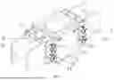
FIG. 1 is a schematic perspective structural view of a high-strength steel structure joint connection device according to the disclosure.
FIG. 2 is a schematic side cross-sectional view of the high-strength steel structure joint connection device according to the disclosure.
FIG. 3 is a schematic front cross-sectional view of the high-strength steel structure joint connection device according to the disclosure.
FIG. 4 is a partial enlarged view of a section A in FIG. 1 according to the disclosure.
FIG. 5 is a partial enlarged view of a section B in FIG. 2 according to the disclosure.
Reference Numerals: 1: threaded hole, 2: connection seat, 3: inner locking block, 4: steel structure body, 5: adapter plate, 6: drain outlet, 7: cross slot, 8: push rod, 9: device body, 10: buffer spring, 11: damper, 12: rotating plate, 13: sleeve, 14: fixing bolt, 15: turntable, 16: accommodation groove, 17: sliding groove, 18: threaded cylinder, 19: sliding block, 20: return spring, 21: connection plate, 22: inclined surface, 23: fan blade, 24: bracket, 25: fan pipe, 26: support rod, 27: protective plate, 28: motor, 29: bearing plate, 30: heating cavity, 31: air outlet, 32: sealing plate, 33: heating plate.
DETAILED DESCRIPTION OF EMBODIMENTS
The technical solutions in the embodiments of the disclosure will be described clearly and completely below with reference to the accompanying drawings. Apparently, the described embodiments are only some, not all, embodiments of the disclosure. All other embodiments obtained by those of ordinary skill in the art based on the embodiments of the disclosure without creative efforts shall fall within the protection scope of the disclosure.
Please refer to FIGS. 1-5, a high-strength steel structure joint connection device disclosed by the disclosure is illustrated.
The high-strength steel structure joint connection device provided by the disclosure includes a device body 9, a connection seat 2, inner locking blocks 3, and a steel structure body 4.
The connection seat 2 and the inner locking blocks 3 are disposed on two opposite side surfaces of the device body 9. The inner locking blocks 3 are disposed inside the connection seat 2, and a gap is formed between the connection seat 2 and each inner locking block 3. The steel structure body 4 is inserted into the gap between the connection seat 2 and each inner locking block 3. The steel structure body 4 and the connection seat 2 are detachably and fixedly connected through a positioning mechanism.
Specifically, the device body 9 is used to carry the overall members. The connection seat 2 and the inner locking blocks 3 are used to connect the steel structure body 4 and fix the position of the steel structure body 4. The steel structure body 4 is detachably and fixedly connected between the connection seat 2 and the inner locking block 3. The connection seat 2, the inner locking block 3, and the steel structure body 4 are each provided with multiple threaded holes 1 for connecting fixing bolts 14, so that the steel structure body 4 can be fixed after being inserted into the gap between the connection seat 2 and the inner locking block 3.
The positioning mechanism includes multiple threaded holes 1 defined on side surfaces of the connection seat 2 adjacent to the device body 9 and fixing bolts 14 screwed into the threaded holes 1. The inner wall of each threaded hole 1 is threadedly connected to the fixing bolt 14. Each threaded hole 1 sequentially penetrates through the side walls of the steel structure body 4 and the inner locking block 3 in a direction perpendicular to the side surface of the connection seat 2. The outer end of each fixing bolt 14 is fixedly provided with a rotating plate 12 for driving the fixing bolt 14 to rotate, facilitating the rotation of the fixing bolt 14.
To further optimize the above technical solution and enhance the connection stability of the device, in this embodiment, each fixing bolt 14 is provided with a threaded cylinder 18 therein, and the threaded cylinder 18 is arranged along an axial direction of the fixing bolt 14. A push rod 8 is screwed into the threaded cylinder 18. The side wall of the inner end of the fixing bolt 14 defines a sliding groove 17. A sliding block 19 is disposed in the sliding groove 17. The inner end of the sliding block 19 is movably connected to the sliding groove 17. The contact surfaces of the push rod 8 and the sliding block 19 are each provided with an inclined surface 22. When the push rod 8 is screwed inward, the push rod 8 pushes the free end of the sliding block 19 out of the sliding groove 17.
It should be noted that the sliding block 19 is slidably connected to the inner surface of the sliding groove 17. The sliding groove 17 is used to accommodate the sliding block 19 and allow the sliding block 19 to be actuated within the sliding groove 17, so that when the sliding block 19 slides out, it locks against the inner surface of the inner locking block 3 from the inside, thereby preventing the fixing bolt 14 from detaching. The sliding block 19 and the inner surface of the inner locking block 3 are movably abutted.
Specifically, to achieve the sliding out of the sliding block 19, the sliding groove 17 communicates with the threaded cylinder 18. The inner surface of the threaded cylinder 18 is threadedly connected to the push rod 8. Both the push rod 8 and the sliding block 19 are provided with inclined surfaces 22 to facilitate contact between the push rod 8 and the sliding block 19. The outer end of the push rod 8 is provided with a cross slot 7. By using a compatible cross-tip screwdriver to continuously screw the push rod 8 into the threaded cylinder 18, the inclined surface 22 on the push rod 8 and the inclined surface 22 on the sliding block 19 begin to contact, and the contact area gradually increases. Through the movable abutment connection between the push rod 8 and the sliding block 19, the sliding block 19 is pushed out.
To further optimize the above technical solution and enable convenient disassembly and reuse of the device, in this embodiment, an accommodation groove 16 is provided on the sliding groove 17. The side surface of the inner end of the sliding block 19 is fixedly connected to a connection plate 21. The connection plate 21 is movably connected to the accommodation groove 16. The side surface of the connection plate 21 is fixedly connected to an end of a return spring 20. The other end of the return spring 20 is fixedly connected to the inner surface of the accommodation groove 16. When the push rod 8 is unscrewed outward, the return spring 20 is used to pull the sliding block 19 back to its reset position.
Specifically, the sliding groove 17 is provided with the accommodation groove 16 for connecting the return spring 20, and the side surface of the sliding block 19 is fixedly connected with the connection plate 21. In order to movably connect the connection plate 21 with the accommodation groove 16, an end of the return spring 20 is fixedly connected with the side surface of the connection plate 21, and the other end of the return spring 20 is fixedly connected with the inner surface of the accommodation groove 16, so that when the push rod 8 is screwed out, the return spring 20 pulls back the sliding block 19 to reset, thereby allowing the fixing bolt 14 to be unscrewed from the threaded hole 1, releasing the fixation between the connection seat 2 and the steel structure body 4.
To further optimize the above technical solution, the rotating plate 12 is threadedly connected to a sleeve 13. The inner surface of the sleeve 13 is fixedly connected to a buffer spring 10 and a damper 11. The damper 11 is disposed inside the buffer spring 10. The damper 11 and the buffer spring 10 cooperate to push the sleeve 13 against the connection seat 2 to absorb vibration and impact, and to relatively fix the fixing bolt 14 and the threaded hole 1 through a reaction force.
Specifically, the sleeve 13 is used to internally connect the buffer spring 10 and the damper 11. The damper 11 is used, in cooperation with the buffer spring 10, to press against the connection seat 2, fixing the fixing bolt 14 through the reaction force, and also capable of absorbing vibration and impact, increasing the fixing strength. An end of the sleeve 13 is also provided with a cross slot 7 for engagement with a cross-tip screwdriver for rotation.
To further optimize the above technical solution, the other end of the damper 11 and the buffer spring 10 is fixedly connected to an adapter plate 5. The surface of the adapter plate 5 facing towards the connection seat 2 is rotatably connected to a turntable 15. The turntable 15 is movably abutted against the side surface of the connection seat 2. The rotatable connection between the turntable 15 and the adapter plate 5 is used to prevent the turntable 15 from causing the buffer spring 10 and the damper 11 to twist together when rotating.
To further optimize the above technical solution, the inner surface of the device body 9 is fixedly connected to a bearing plate 29 and a sealing plate 32. A heating cavity 30 is formed between the bearing plate 29 and the sealing plate 32, and the sealing plate 32 is located below the bearing plate 29. The side surface of the device body 9 provided with the connection seat 2 is provided with an air outlet 31. The air outlet 31 communicates with the heating cavity 30 and is used to blow gas from the heating cavity 30 towards the fixing bolt 14.
Specifically, the inner surface of the device body 9 is fixedly connected to the bearing plate 29. The upper surface of the bearing plate 29 is fixedly connected to a fan pipe 25 communicating with the heating cavity 30, thereby enabling the device body 9 to connect to the fan pipe 25. The heating cavity 30 is used to store heated air flow inside. The air outlet 31 is used to blow air towards the fixing bolt 14 when the fan assembly is activated.
The upper surface of the sealing plate 32 is provided with a heating plate 33 for heating the air in the heating cavity 30. The upper surface of the bearing plate 29 is fixedly connected to the fan pipe 25 communicating with the heating cavity 30. The inner wall of the fan pipe 25 is provided with a fan assembly. The fan assembly is used to discharge the gas heated by the heating plate 33 from the heating cavity 30 and blow it towards the fixing bolt 14 through the air outlet 31.
Specifically, the heating plate 33 is located inside the heating cavity 30. The fan pipe 25 is used to connect and secure the fan assembly. The fan assembly blows the gas heated by the heating plate 33 towards the fixing bolt 14, used for de-icing in cold seasons and preventing the connection device from freezing.
It should be noted that the fan assembly includes a motor 28 and a bracket 24 for fixedly connecting the motor 28. The output end of the motor 28 is provided with a fan blade 23. The motor 28 drives the fan blade 23 to rotate, drawing external air into the heating cavity 30. The bracket 24 is fixedly connected to the inner wall of the fan pipe 25. The upper surface of the bearing plate 29 is provided with a protective plate 27 for protecting the fan assembly.
Specifically, the upper surface of the bearing plate 29 is fixedly connected to a support rod 26. The upper end of the support rod 26 is fixedly connected to the protective plate 27. The fan assembly is located below the protective plate 27. The protective plate 27 is used to protect the fan assembly from environmental erosion and pressure damage.
To further optimize the above technical solution, the device body 9 is provided with a drain outlet 6. The drain outlet 6 is located on the other two side surfaces of the device body 9 (i.e., the side surfaces adjacent to the connection seat 2), communicates with the outer surface of the bearing plate 29, and is used to promptly drain water from the surface of the bearing plate 29 to prevent rust and freezing caused by water accumulation on the surface of the bearing plate 29.
It should be noted that the bearing plate 29, the sealing plate 32, and the heating cavity 30 formed thereby can be provided in two sets, arranged symmetrically up and down on the inner surface of the device body, to perform de-icing and other operations at multiple fixing bolts 14. Similarly, the fan assembly and other devices are correspondingly provided as needed.
A method for using the high-strength steel structure joint connection device of the disclosure is as follows.
During installation, the steel structure body 4 is inserted into the gap between the connection seat 2 and the inner locking block 3. After insertion, the fixing bolt 14 is inserted into the threaded hole 1. The rotating plate 12 is used to screw the fixing bolt 14 into the threaded hole 1 until the free end of the sliding block 19 passes beyond the inner surface of the inner locking block 3. A cross-tip screwdriver is used to screw the push rod 8 inward so that it advances inward and contacts the sliding block 19. Under the action of the inclined surfaces 22, the free end of the sliding block 19 is pushed out. After being pushed out, then the fixing bolt 14 is unscrewed outward until the free end of the sliding block 19 abuts against the inner surface of the inner locking block 3 from the inside outward, forming a stable mechanical locking structure. Subsequently, a cross-tip screwdriver is used to screw the sleeve 13 inward so that it drives the buffer spring 10 and the damper 11 to move inward, causing the turntable 15 to contact the side surface of the connection seat 2, compressing the buffer spring 10 and the damper 11 to form a reaction force to fix the fixing bolt 14. When the steel structure body 4 is subjected to vibration or impact, the buffer spring 10 and the damper 11 can absorb and dissipate energy, ensuring the fixing bolt 14 does not become loose. During disassembly, a cross-tip screwdriver is used to unscrew the sleeve 13 outward, loosening the buffer spring 10 and the damper 11. Subsequently, a cross-tip screwdriver is used to unscrew the push rod 8 outward. After the push rod 8 is unscrewed outward, the return spring 20 pulls the sliding block 19 inward to reset. Subsequently, the fixing bolt 14 is unscrewed and the steel structure body 4 is removed from the connection seat 2.
The above description of the disclosed embodiments enables any person skilled in the art to make or use the disclosure. Various modifications to these embodiments will be readily apparent to those skilled in the art, and the generic principles defined herein may be applied to other embodiments without departing from the spirit or scope of the disclosure. Therefore, the disclosure is not intended to be limited to the embodiments shown herein but is to be accorded the widest scope consistent with the principles and novel features disclosed herein.
Claims
What is claimed is:1. A high-strength steel structure joint connection device, comprising:
a device body (9);
a connection seat (2), disposed on two opposite side surfaces of the device body (9);
an inner locking block (3), disposed inside the connection seat (2) and fixedly connected to one of the side surfaces of the device body (9); and
a steel structure body (4), inserted between the connection seat (2) and the inner locking block (3), wherein the steel structure body (4) and the connection seat (2) are detachably and fixedly connected through a positioning mechanism;
wherein the positioning mechanism comprises:
a threaded hole (1), defined on a side surface of the connection seat (2) adjacent to the device body (9);
a fixing bolt (14), screwed into the threaded hole (1); wherein the threaded hole (1) sequentially penetrates through side walls of the steel structure body (4) and the inner locking block (3) in a direction perpendicular to the side surface of the connection seat (2); and
a rotating plate (12), disposed on an outer end of the fixing bolt (14); wherein the rotating plate (12) is configured to drive the fixing bolt (14) to rotate;
wherein the fixing bolt (14) is provided with a threaded cylinder (18) therein, the threaded cylinder (18) is arranged along an axial direction of the fixing bolt (14), a push rod (8) is screwed into the threaded cylinder (18), a side wall of an inner end of the fixing bolt (14) defines a sliding groove (17), a sliding block (19) is disposed in the sliding groove (17), an inner end of the sliding block (19) is movably connected to the sliding groove (17), each of contact surfaces of the push rod (8) and the sliding block (19) is provided with an inclined surface (22), and when the push rod (8) is screwed inward, the push rod (8) pushes a free end of the sliding block (19) out of the sliding groove (17);
wherein the sliding groove (17) is provided with an accommodation groove (16), a side surface of the inner end of the sliding block (19) is fixedly connected to a connection plate (21), the connection plate (21) is movably connected to the accommodation groove (16), a side surface of the connection plate (21) is fixedly connected to an end of a return spring (20), and another end of the return spring (20) is fixedly connected to an inner surface of the accommodation groove (16), and when the push rod (8) is unscrewed outward, the return spring (20) pulls the sliding block (19) back to reset; and
wherein the rotating plate (12) is threadedly connected to a sleeve (13), an inner surface of the sleeve (13) is fixedly connected to a buffer spring (10) and a damper (11), the damper (11) is disposed inside the buffer spring (10), and the damper (11) and the buffer spring (10) cooperate to push the sleeve (13) against the connection seat (2) to absorb vibration and impact, and to relatively fix the fixing bolt (14) and the threaded hole (1) through a reaction force.
2. The high-strength steel structure joint connection device according to claim 1, wherein another end of the damper (11) and the buffer spring (10) is fixedly connected to an adapter plate (5), a surface of the adapter plate (5) close to the connection seat (2) is rotatably connected to a turntable (15), the turntable (15) is movably abutted against a side surface of the connection seat (2), and a rotatable connection between the turntable (15) and the adapter plate (5) is configured to prevent the turntable (15) from driving the buffer spring (10) and the damper (11) to twist together when rotating.
3. The high-strength steel structure joint connection device according to claim 1, wherein an inner surface of the device body (9) is fixedly connected to a bearing plate (29) and a sealing plate (32), a heating cavity (30) is defined between the bearing plate (29) and the sealing plate (32), the sealing plate (32) is disposed below the bearing plate (29), a side surface of the device body (9) provided with the connection seat (2) defines an air outlet (31), and the air outlet (31) is connected with the heating cavity (30) and configured to blow gas from the heating cavity (30) towards the fixing bolt (14).
4. The high-strength steel structure joint connection device according to claim 3, wherein an upper surface of the sealing plate (32) is provided with a heating plate (33) configured to heat air in the heating cavity (30), an upper surface of the bearing plate (29) is fixedly connected to a fan pipe (25) connected with the heating cavity (30), an inner wall of the fan pipe (25) is provided with a fan assembly, and the fan assembly is configured to discharge gas heated by the heating plate (33) from the heating cavity (30) and blow the gas towards the fixing bolt (14) through the air outlet (31).
5. The high-strength steel structure joint connection device according to claim 4, wherein the fan assembly comprises a motor (28) and a bracket (24) fixedly connected to the motor (28), an output end of the motor (28) is provided with a fan blade (23), the motor (28) is configured to drive the fan blade (23) to rotate to draw external air into the heating cavity (30), the bracket (24) is fixedly connected to an inner wall of the fan pipe (25), and the upper surface of the bearing plate (29) is provided with a protective plate (27) configured to protect the fan assembly.
6. A method for using the high-strength steel structure joint connection device according to claim 2, comprising:
during assembly, inserting the steel structure body (4) into a gap between the connection seat (2) and the inner locking block (3), then inserting the fixing bolt (14) into the threaded hole (1), screwing the fixing bolt (14) into the threaded hole (1) via the rotating plate (12) until the free end of the sliding block (19) passes beyond an inner surface of the inner locking block (3), using a cross screwdriver to screw the push rod (8) inward to make the push rod (8) contact the sliding block (19), thereby making the free end of the sliding block (19) be pushed out under an action of the inclined surfaces (22), after being pushed out, unscrewing the fixing bolt (14) outward until the free end of the sliding block (19) abuts against the inner surface of the inner locking block (3) from inside to outside to form a stable mechanical locking structure, subsequently, using a cross screwdriver to screw the sleeve (13) to drive the buffer spring (10) and the damper (11) to move inward, making the turntable (15) contact the side surface of the connection seat (2), and compressing the buffer spring (10) and the damper (11) to form a reaction force to fix the fixing bolt (14), wherein when the steel structure body (4) is subjected to vibration or impact, the buffer spring (10) and the damper (11) absorb and dissipate energy, and the fixing bolt (14) does not become loose; and
during disassembly, using a cross screwdriver to unscrew the sleeve (13) outward, loosening the buffer spring (10) and the damper (11), subsequently, using a cross screwdriver to unscrew the push rod (8) outward, after the push rod (8) is unscrewed outward, pulling the sliding block (19) inward to reset via the return spring (20), subsequently, unscrewing the fixing bolt (14), and removing the steel structure body (4) from the connection seat (2).
Images & Drawings included:


Sources:
- United States Patent and Trademark Office - verify current appl. status at the USPTO↗
Recent applications in this class:
- » 20260117510 2026-04-30
MEZZANINE SYSTEM AND INSTALLATION - » 20260110170 2026-04-23
MODULAR WALL JUNCTIONS BRACKET SYSTEMS AND METHODS - » 20260103880 2026-04-16
BEAM CONNECTION SYSTEMS AND METHODS - » 20260078576 2026-03-19
ENGINEERED BEAM WITH ADJUSTABLE ANGLE CONNECTION - » 20260078575 2026-03-19
PREFABRICATED CONSTRUCTION STRUCTURE, PREFABRICATED MAIN STRUCTURE, AND PREFABRICATED BUILDING - » 20260015852 2026-01-15
Building System - » 20260015851 2026-01-15
ADJUSTABLE STRUCTURAL SUPPORT - » 20250354368 2025-11-20
SUPPORT BEAM FOR SCREENED ENCLOSURE AND CONNECTORS THEREFORE - » 20250305270 2025-10-02
CORNER CONNECTOR - » 20250263919 2025-08-21
BEAM-TO-COLUMN JOINT CONNECTION
Recent applications for this Assignee:
- » 20260147964 2026-05-28
Regional seismic liquefaction space-time field construction method fusing physical simulation and machine learning - » 20260139832 2026-05-21
OPTICAL DIAGNOSIS SYSTEM AND METHOD FOR IGNITION OF SINGLE-PARTICLE EXCAVATE WASTE - » 20260134357 2026-05-14
METHOD FOR ONLINE COORDINATED OPTIMIZATION SCHEDULING OF TRUCK MOBILE CHARGING STATIONS - » 20260117134 2026-04-30
SYSTEM AND METHOD FOR PREPARING HYDROGEN-RICH SYNGAS BY TAKING BIOGAS AS COMPOSITE GASIFICATION AGENT FOR GASIFICATION OF BIOGAS RESIDUE - » 20260107628 2026-04-16
SYNTHESIS METHOD FOR HEXAPHENYLBENZENE-BASED ORGANIC SMALL MOLECULES AND APPLICATION IN ELECTROLUMINESCENT DEVICES - » 20260099639 2026-04-09
CALCULATION, PLANNING, AND CONFIGURATION METHOD FOR MAXIMUM LATENCY OF POWER DISTRIBUTION NETWORK INTEGRATED WITH IDC - » 20260091044 2026-04-02
APPLICATION OF CARBASALATE CALCIUM IN PREPARING DRUG FOR TREATMENT OF HYDROCEPHALUS - » 20260080119 2026-03-19
METHOD AND DEVICE FOR PREDICTING LONG-TERM CREEP DATA BASED ON SHORT-TERM CREEP DATA - » 20260063086 2026-03-05
Value-moving deviation method for acquiring cycle-stage combustion parameters of engine based on multiple sensing signals - » 20260061404 2026-03-05
CO-LOADED CARBON-BASED CATALYST, PREPARATION METHOD AND APPLICATION THEREOF