SUPPORT SYSTEMS AND METHODS FOR SUPPORTING STUD RAIL ASSEMBLIES
US20260146449A1
2026-05-28
19/399,421
2025-11-24
Smart Summary: A support system helps hold two parts of a stud rail assembly in place while concrete is poured. It includes a support structure with a special slot and opening for easy adjustments. One part of the assembly has a slot that allows movement, while the other part has an opening that supports rotation. This setup lets the first part move and rotate as needed. Overall, the system keeps the assembly stable in the right position during construction. 🚀 TL;DR
Abstract:
A support system for a stud rail assembly having first and second stud rail members supported on a form for a concrete structure. The support system comprises a support structure, a support slot and a support opening. The support structure defines a support member, and a connection projection. The first stud rail member defines a support slot and the second stud rail member defines a support opening. The connection projection can extend through the support slot so the connection projection is movable within the support slot to allow movement of the first stud rail member. The support opening can receive the connection projection, so the first stud rail member is supported for rotation relative to the support structure and the second stud rail member. The support system is arranged to support the stud rail assembly in a desired location and configuration relative to the form.
Inventors:
- Scott McCornack 3 🇺🇸 Ferndale, WA, United States
- Joshua Hupp 3 🇺🇸 Sedro-Woolley, WA, United States
Assignee:
- Morse Distribution, Inc. 3 🇺🇸 Bellingham, WA, United States
Applicant:
Interested in similar patents?
Get notified when new applications in this technology area are published.
Classification:
E04C5/168 » CPC main
Reinforcing elements, e.g. for concrete; Auxiliary elements therefor; Auxiliary parts for reinforcements, e.g. connectors, spacers, stirrups Spacers connecting parts for reinforcements and spacing the reinforcements from the form
E04C5/0645 » CPC further
Reinforcing elements, e.g. for concrete; Auxiliary elements therefor; Reinforcing elements of metal, e.g. with non-structural coatings of high bending resistance, i.e. of essentially three-dimensional extent, e.g. lattice girders Shear reinforcements, e.g. shearheads for floor slabs
E04C5/16 IPC
Reinforcing elements, e.g. for concrete; Auxiliary elements therefor Auxiliary parts for reinforcements, e.g. connectors, spacers, stirrups
E04C5/06 IPC
Reinforcing elements, e.g. for concrete; Auxiliary elements therefor; Reinforcing elements of metal, e.g. with non-structural coatings of high bending resistance, i.e. of essentially three-dimensional extent, e.g. lattice girders
Description
This application (Attorney's Ref. No. P220727) claims benefit of U.S. Provisional Application Ser. No. 63/725,813 filed Nov. 27, 2024, the contents of which are incorporated herein by reference.
TECHNICAL FIELD
The present invention relates to support systems for stud rail assemblies and, more specifically, support systems and methods for supporting stud rail assemblies on a concrete structure.
BACKGROUND
Stud rail systems and assemblies are engineered for use at a specific location to reinforce concrete structures. The stud rail assemblies comprise multiple configurations or require assembly to ensure the stud rail system is securely attached to a structure at a specific location.
To secure the stud rail assembly at a desired location, the stud rail assembly must be supported by a support system. However, the stud rail assembly is typically engineered to be arranged in a desired position and orientation relative to the support system can require precise alignment of the stud rail assembly and the concrete structure.
Thus the need exists for improved support systems and methods that are efficient and easier to support stud rail assemblies so the stud rail assemblies can be precisely and accurately arranged in a desired position and orientation on a form for the concrete structure.
RELATED ART
U.S. Pat. No. 11,959,270 discloses stud rail systems and methods for use in reinforced concrete structures.
SUMMARY
The present invention can be embodied as a support system for a stud rail assembly supported on a form for a concrete structure, where the stud rail assembly has a first stud rail member and a second stud rail member, the support system comprising a support structure, a support slot, and a support opening. The support structure defines a support portion, a connection projection configured to extend from the support portion. The support slot is defined by the first stud rail member. The support opening is defined by the second stud rail member. The connection projection is configured to extend through the support slot such that the connection projection is movable within the support slot to allow movement of the first stud rail member relative to the support structure. The support opening is configured to receive the connection projection such that the first stud rail member is supported for rotation relative to the support structure and the second stud rail member about a pivot axis defined by the connection projection, and the pivot axis is movable relative to the first stud rail member. The support system is arranged to support the stud rail assembly at a desired location and in a desired configuration relative to the form.
The present invention can be embodied as a support system for a stud rail system supported on a form for a concrete structure, where the stud rail assembly has a plurality of first stud rail members and a plurality of second stud rail members, the support system comprising a plurality of support structures, a plurality of support slots, and a plurality of support openings. The plurality of support structures each define a primary member defining a support portion, and a secondary member defining a connection projection configured to extend from the primary member. At least one support slot is defined by each of the plurality of first stud rail members. At least one support opening defined by each of the plurality of second stud rail members. Each connection projection is configured to extend through a corresponding support slot defined by one of the plurality of first stud rail members such that each connection projection is movable within one of the support slots to allow movement of one of the first stud rail members relative to the support structure. Each support opening is configured to receive one of the connection projections such that each of the plurality of first stud rail members is supported for rotation relative to the support structure and at least one of the plurality of second stud rail members about a pivot axis defined by one of the connection projections, and each pivot axis is movable relative to at least one of the plurality of first stud rail members. The plurality of first stud rail members are connected to the plurality of second stud rail members at a plurality of axis points defined by each pivot axis to allow the stud rail assembly to be reconfigured between a collapsed configuration and an expanded configuration. The support assembly is arranged to support the stud rail assembly at a desired location and in a desired configuration relative to the form.
The present invention can further be embodied as a method for supporting a stud rail assembly with a support system, the stud rail assembly having a first stud rail member and a second stud rail member to be supported on a form for a concrete structure. A support structure is provided, where the support structure defines a support portion, and a connection projection configured to extend from the support portion. A support slot is provided defined by the first stud rail member. A support opening is provided defined by the second stud rail member. The connection projection is extended through the support slot so the connection projection is movable within the support slot to allow movement of the first stud rail member relative to the support structure. The support opening is configured to receive the connection projection such that the first stud rail member is supported for rotation relative to the support structure and the second stud rail member about a pivot axis defined by the connection projection, and the pivot axis is moveable relative to the first stud rail member. The support system is arranged to support the stud rail assembly at a desired location and in a desired configuration relative to the form.
BRIEF DESCRIPTION OF THE DRAWINGS
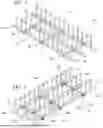
FIG. 1 is a perspective view of the first example support system attached to a stud rail assembly;
FIG. 2 is a bottom perspective view of the first example support system attached to the stud rail assembly;
FIG. 3 is a top plan view of the form for a concrete structure prior to placement of the support system;
FIG. 4 is a side elevational view of the concrete structure prior to the placement of the stud rail assemblies;
FIG. 5 is a top plan view of the stud rail assemblies secured to the concrete structure with the support system;
FIG. 6 is a side elevational view of the stud rail assemblies secured to the concrete structure with the support system;
FIG. 7 is a side elevational view of the stud rail assemblies secured to the concrete structure with the support system after concrete is poured;
FIG. 8 is a top plan view of the stud rail assembly being depicted in an expanded configuration;
FIG. 9 is a top plan view of the stud rail assembly being depicted in a collapsed configuration;
FIG. 10 is a close up side view of the support system attached to the stud rail system;
FIG. 11 is a top cross-sectional view of the line 11-11 in FIG. 10, showing the support slots;
FIG. 12 is a top cross-sectional view of the line 11-11 in FIG. 10, showing the support slots;
FIG. 13 is a top plan view of the stud rail assembly in which the support assemblies permit movement of the rail portions;
FIG. 14 is a perspective view of the first example support structure; and,
FIG. 15 is a close-up cross-sectional view of the support system secured to the form for a concrete structure.
DETAILED DESCRIPTION
FIGS. 1 and 2 are perspective views of a first example support system 20 for a stud rail assembly 22 constructed in accordance with, and embodying, the principles of the present invention. FIGS. 1 and 2 illustrate that at least a portion of the first example support system 20 is secured relative to the stud rail assembly 22. As shown in FIGS. 3 and 4, stud rail assembly 22 is conventionally attached to or supported by a form 24 for a reinforced concrete deck structure 26 (FIG. 7). The example reinforced concrete deck structure 26 (FIG. 7) is in turn supported by a column structure 28 (FIGS. 3-7). The example reinforced concrete deck structure 26 and column structure 28 are or may be conventional and will not be described herein beyond that extend helpful to a complete understanding of the construction and operation of the principles of the present invention.
The example stud rail assembly 22 comprises a plurality of cross portions, or first stud rail members, 30 and a plurality of rail portions, or second stud rail members, 32, where each rail portion 32 defines one or more pin projections 34. As generally shown in FIG. 4, the column structure 28 supporting the example reinforced concrete deck structure 26 is a reinforced concrete structure comprising a rebar structure 36. When the support system 20 and the stud rail assembly 22 are attached to or supported by the form 24, concrete in liquid form can be poured onto the form 24 around the stud rail assembly 22 and at least a portion of the rebar structure 36 to create the reinforced concrete deck structure 26.
As perhaps best shown in FIGS. 14 and 15, the example support system 20 comprises at least one support structure 50, at least one support slot 52 defined by each of the cross portions 30, and at least one support opening 54 defined by each of the rail portions 32. The example support structure 50 defines a support portion 60 and a connection projection 62 configured to extend from the support portion 60.
The example connection projection 62 is configured to extend through the support slot 52 such that at least one connection projection 62 is movable within at least one support slot 52 to allow movement of at least one of the first stud rail members 30 relative to the support structure 50. Each support opening 54 is configured to receive one of the connection projections 62 such that the cross portion 26 is supported for rotation relative to the support structure 50 and the rail portion 32 about a pivot axis P defined by one of the connection projections 62 and such that the pivot axis P is movable relative to the cross portion 26. The support system 20 is arranged to support the stud rail assembly 22 in a desired configuration relative to the form 24 as shown, for example, in FIGS. 5-7.
With the foregoing general description of the construction and operation of the present invention in mind, the details of the example support system 20 will now be described in further detail.
The stud rail assembly 22 is or can be constructed in accordance with the stud rail system of U.S. Pat. No. 11,959,270. As depicted in FIG. 5, the example stud rail system comprises first, second, third, and fourth stud rail assemblies 22a, 22b, 22c, and 22d. In the following discussion, letter appendices to a numerical reference character indicate individual instances of the element identified by that reference character and not an element different from that identified by that reference character.
As perhaps best shown in FIGS. 1 and 2, each stud rail assembly 22 comprises a plurality of the cross portions 30 and a plurality of the rail portions 32 and the example support system 20 comprises a plurality of the support structures 50. As perhaps best shown in FIG. 2, the example stud rail assembly 22 comprises first, second, and third cross portions 30a, 30b, and 30c and first, second, and third rail portions 32a, 32b, and 32c. The example stud rail assembly 22 comprising three of the rail portions 30 and three of the cross portions 32 thus defines nine intersection points, and one of the support structures 50 is associated with each of these intersection points. Accordingly, the example support system 50 comprises first, second, third, fourth, fifth, sixth, seventh, eighth, and ninth support structures 50a, 50b, 50c, 50d, 50e, 50f, 50g, 50h, and 50i, one located at each intersection point. Depending on the structural requirements of the completed reinforced form 24, stud rail assemblies with different numbers of rail portions and cross portions may be used to define different numbers of intersection points, in which case different numbers of support structures 50 may be provided.
The example support structures 50 may be made of a single piece of molded, milled, or fabricated material but may desirably be made of multiple parts to facilitate fabrication, assembly, and installation. The example support structure 50 may be constructed from one or more materials, including composite materials, polymers. metals, and/or combinations thereof, that provide a desirable mix of low cost, corrosion resistance, and structural integrity. The example support structures 50 are typically made of one or more injection molded plastic parts.
FIGS. 14 and 15 illustrate that at least one of the example support structures 50 defines a primary member 120 and, optionally, a secondary member 122. The example primary member 120 defines the support portion 60 and the connection projection 62 of the support structures 50 as generally described above. The example connection projection 62 defines a connecting axis C. The example primary member 120 further defines a structure wall 130 defining a primary member upper surface 132 and a primary member lower surface 134. The primary member upper surface 132 is configured to engage one of the cross portions 30 to support the example stud rail assembly 22 as best shown in FIG. 15.
The example connection projection 62 extends from the primary member upper surface 132. The example connection projection 62 is substantially cylindrical in cross-section, but a connection portion 62 constructed in accordance with the present invention may take other cross-sectional shapes. The example connection projection 62 is configured to extend through the support slot 52 to allow movement of the connecting axis C along a longitudinal axis of the cross portion 30 and rotation of the rail portions 32 about the connecting axis C.
Extending from lower surface 134 of the example primary member 120 is a reinforcement portion 140 and one or more leg portions 142. The example reinforcement portion 140 defines a reinforcement cavity 144 adapted to receive the secondary member 122 of the support structure(s) 50. Each of the example secondary members 122 is a cylindrical member, and the example reinforcement cavity 144 is an annular groove adapted to receive an upper edge of one of the secondary members 122 as depicted in FIGS. 14 and 15. Alternatively, different configurations of reinforcement cavities 144 (e.g., more than one cavity; shapes other than cylindrical) and secondary members 122 (e.g., a projection for each cavity; shapes other than cylindrical) may be used to secure the secondary member 122 to the primary member 120. In any case, each of the example reinforcement cavities 144 is sized and dimensioned to receive one or more portions of the secondary members 122 to secure one of the secondary members 122 to one of the primary members 120. Fastening methods such as friction, adhesive, and/or spin welding can be used, separately or in combination, to secure the secondary members 122 to the primary members 120.
Each of the example leg portions 142 defines an optional fastener opening 150. The fastener openings 150 are sized and dimensioned to receive fasteners 152 as will be described in further detail below.
The example primary members 120 define three of the leg portions 142a, 142b, and 142c to provide stable support for the example stud rail assembly 22. More than three leg portions 142 may be provided. Alternatively, one or two of the leg portions 142 may be provided if the one or two leg portions 142 are configured to provide stable support for the example stud rail assembly 22 during installation and use. In addition, one or more brace walls 160 may be arranged to extend between adjacent leg portions 142 and the structure wall 130 to rigidify the support structures 50 by bracing the leg portions 142. With the example primary member 120 defining three of the leg portions 142, three of the brace walls 160 are connected to the structure wall 130 and arranged to extend between pairs of adjacent leg portions 142.
When secured the primary member 120, the example secondary member 122 is substantially coaxially aligned with the connecting axis C defined by the connection projection 62 extending from primary member upper surface 132. The example secondary member 122 is hollow and cylindrically shaped and can be easily formed using a conventional injection molding process. If used, the example secondary member 122 can be positioned below the connection projection 62 to provide additional support to the structure wall 60 below the connection projection 62.
The example fastener(s) 152 is or may be a nail, screw, or the like that may be extended at least partly through the fastener opening(s) 150 and into the form 24 for the reinforced concrete deck structure 26. The fastener(s) 152 are used to secure the support structure(s) 50 in a desired position and configured relative to the column portion and the form 24 to ensure that the stud rail assembly 22 is in a desired position and orientation relative to the reinforced concrete deck structure 26.
As perhaps best shown in FIGS. 14 and 15, the example support structure 50 defines a height dimension H. When the support structure 50 is secured to the plurality of cross portion(s) 26 and the plurality of rail portion(s) 28, the height dimension H determines a spacing between the form 24 and a bottom of the stud rail assemblies 22. This spacing, and thus the height dimension H of the support structure 50, is or may be predetermined based on the structural requirements of the form 24 and/or the reinforced concrete deck structure 26.
The cross portions 30 each define at least one support slot 52. As generally described above, one support slot 52 is typically provided for each rail portion 32 that intersects a given cross portion 30. Each support slot 52 is configured to guide the connection projection 62 in a variable position. The example support slot 52 is an elongated opening formed in the cross portion 30 and defines a slot length L and a slot width W. The support slot 52 is configured to allow the adjustable movement of the connection projection 62 along the slot length L. The example support slot 52 is linear and features parallel sidewalls that define the slot width W, which is larger than the diameter or thickness of the connection projection 62. The example support slot 52 need not be linear and may be curved or otherwise configured as may be determined by the structural function of a given stud rail assembly 22.
Each of the plurality of rail portions 32 defines at least one support opening 54. The support opening 54 is configured to receive at least a portion of the connection projection 62. The example support opening 54 is positioned on each rail portion 32 such that each support opening 54 can be aligned with or supported in an assembly position relative to at least a portion of a given support slot 52. When the support opening 54 is arranged in the assembly position relative to an associated support slot 52, at least a portion of each connection projection 62 may be extended through a given support slot 52 and one support opening 54 associated with that given support slot as shown, for example, in FIG. 15.
The example support system 20 may comprise one or more engaging member(s) 170. Each engaging member 170 is configured to engage a corresponding connection projection 62 to ensure a secure connection when the connection projection 62 is inserted at least partly through the support opening 54 and engaging member 170. The engaging member 170 further inhibits movement of the cross portion(s) 30 and the rail portion(s) 32 along the pivot axis P relative to the support structure(s) 50.
The example engaging member 170 is or may be a conventional retaining clip comprising an inner portion 172 and an outer portion 174. A clip opening 176 is formed in the inner portion 172. As is conventional, the engaging member 170 is press fit onto the corresponding connection projection 62 such that the inner portion engages the corresponding connection projection 62 and the outer portion engages the corresponding rail portion 32. Alternatively, the engaging member 170 can be fastened directly to the rail portions 32, integrally formed on the rail portion 32 inside of the support opening 54, or integrally formed as part of the connection projection 62. At least a portion of the example engaging member 170 can be constructed with a resilient material to allow the connection projection 62 to pass through the clip opening 176 but to frictionally or otherwise engage the connection projection(s) 62 and/or rail portion(s) 32 once inserted or otherwise used to movably attach the rail portion(s) 32 to the cross portion(s) 30. Thus, movement of the cross portions 30 and the rail portions 32 along the connection axis C relative to the support structure 50 is inhibited when the connection projection 62 is engaged with the engaging member 170.
The example support structure 50 is preferably made of or coated with a material that inhibits oxidation of the support structure 50. A typical material from which the support structure 50 is made is plastic, but other materials, coated or uncoated, having structural properties adequate for use as described herein may be used in addition or instead. In an example embodiment, the support structure(s) 50 are plastic so the support structure(s) 50 will not corrode but will prevent water from reaching the stud rail assembly 22. Similarly, when fully inserted into the fastener opening(s) 150, the fastener(s) 152 are spaced from the example stud rail assembly 22 such that water is inhibited or prevented from reaching any component of the example stud rail assembly 22 that is susceptible to oxidation. Further, the example fasteners 152 are preferably made of or coated with a material that inhibits oxidation.
To attach the support structure 50 to the example stud rail assembly 22, the connection projection 62 is inserted at least partly into and through a corresponding support slot 52 in one of the cross portions 30 and then through a corresponding support opening 54 in one of the rail portions 32. The connection projection 62 can then engage with the engaging member 170 to secure the support structure 50 to the cross portions 30 and the rail portions 32.
To support the stud rail assembly 22 with the support system 20, each connection projection 62 is passed in a first direction through one of the support slots 52 and one of the support openings 54, and the support structure 50 is secured to the stud rail assembly 22. When a support assembly is attached to each support slot 52 and support opening 54 defined by the cross portions 30 and rail portions 32, the example engaging members 170 inhibit or prevent movement of the connection projection 62 in a second direction opposite the first direction. However, the connection projections 62 each form an axle that allows pivoting movement of the cross portions 30 relative to the rail portions 32.
The engagement of at least one support system 20 with the stud rail assembly 22 thus secures the plurality of cross portions 30 to the plurality of rail portions 32. With proper arrangement of the support structures 50, the pivoting movement allowed between the plurality of cross portions 30 and the plurality of rail portions 32 about the pivot axis P allows the stud rail assembly 22 to be reconfigured between a collapsed or folded configuration as depicted in FIG. 9 and an expanded or open configuration as depicted in FIG. 8. Alternatively, the support slots 52 may be formed in the rail portions 32 and the support openings 54 may be formed in the cross portions 30 to allow the same pivoting (FIGS. 8 and 9) and arranging (FIG. 11-13) functions as the first example support system 20 described herein.
With the example support system 20 and stud rail assembly 22, arrangement of the example stud rail assembly 22 in the expanded or open configuration as shown in FIG. 8, connection axes C are configured and located in a symmetrical grid 190 at the intersections 192 defining a plurality of axis points corresponding to the connection axes C defined by the connection projections 62. The example stud rail assembly 22 comprising three cross members 30a, 30b, and 30c defines first, second, and third cross axes 194a, 194b, and 194c, first, second, and third rail axes 196a, 196b, and 196c, and first, second, third, fourth, fifth, sixth, seventh, eighth and ninth intersections 192a, 192b, 192c, 192d, 192e, 192f, 192g, 192h, and 192i. In the example stud rail assembly 40, each of the example intersections 192a, 192b, 192c, 192d, 192e, 192f, 192g, 192h, and 192i correspond to locations of the support structures 50a, 50b, 50c, 50d, 50c, 50e, 50f, 50g, 50h, and 50i as described above. Grids with different numbers of cross axes, rail axes, and intersection points may be used depending on the structural requirements of the completed reinforced concrete structure.
Claims
What is claimed is:1. A support system for a stud rail assembly supported on a form for a concrete structure, where the stud rail assembly has a first stud rail member and a second stud rail member, the support system comprising:
a support structure defining
a support portion,
a connection projection configured to extend from the support portion;
a support slot defined by the first stud rail member;
a support opening defined by the second stud rail member; wherein
the connection projection is configured to extend through the support slot such that the connection projection is movable within the support slot to allow movement of the first stud rail member relative to the support structure;
the support opening is configured to receive the connection projection such that
the first stud rail member is supported for rotation relative to the support structure and the second stud rail member about a pivot axis defined by the connection projection, and
the pivot axis is movable relative to the first stud rail member; and
the support system is arranged to support the stud rail assembly at a desired location and in a desired configuration relative to the form.
2. The support system of claim 1, in which the support slot defines a slot length, where the slot length defines the movement of the pivot axis relative to the first stud rail member.
3. The support system of claim 1, further comprising an engaging member configured to engage the connection projection to inhibit movement of the second stud rail member along the pivot axis.
4. The support system of claim 1, in which the support structure further defines at least one fastener opening.
5. The support system of claim 4, further comprising at least one fastener configured to extend through each fastener opening and engage the form to support the support structure in a desired orientation relative to the form.
6. The support system of claim 1, in which the support structure comprises:
a primary member; and
a secondary member.
7. The support system of claim 6, in which the primary member is detachably attached to the secondary member.
8. The support system of claim 6, in which the primary member defines at least one leg portion.
9. The support system of claim 8, in which the support structure further defines at least one fastener opening formed in each leg portion.
10. A method for supporting a stud rail assembly with a support system, the stud rail assembly having a first stud rail member and a second stud rail member to be supported on a form for a concrete structure, the method comprising the steps of:
providing a support structure, where the support structure defines a support portion, and
a connection projection configured to extend from the support portion;
forming a support slot in the first stud rail member;
forming a support opening in the second stud rail member,
extending the connection projection through the support slot so the connection projection is movable within the support slot to allow movement of the first stud rail member relative to the support structure;
configuring the support opening to receive the connection projection such that
the first stud rail member is supported for rotation relative to the support structure and the second stud rail member about a pivot axis defined by the connection projection, and
the pivot axis is moveable relative to the first stud rail member; and
arranging the support system to support the stud rail assembly at a desired location and in a desired configuration relative to the form.
11. The method of claim 10, further comprising the step of providing an engaging member configured to engage the connection projection to inhibit movement of the second stud rail member relative to the pivot axis.
12. The method of claim 10, in which the step of providing a support structure includes defining at least one fastener opening.
13. The method of claim 12, further comprising the step of providing at least one fastener configured to extend through each fastener opening and engage the form to support the support structure in a desired orientation relative to the form.
14. The method of claim 10, in which the step of providing the support structure further comprises providing:
a primary member defining the support portion; and
a secondary member defining the connection projection.
15. The method of claim 14, further comprising detachably attaching the primary member to the secondary member.
16. The method of claim 14, in which the step of providing a primary member further comprises defining at least one leg portion.
17. The method of claim 16, in which the step of providing a support structure further comprises defining at least one fastener opening in each leg portion.
18. A support system for a stud rail system supported on a form for a concrete structure, where the stud rail assembly has a plurality of first stud rail members and a plurality of second stud rail members, the support system comprising:
a plurality of support structures each defining
a primary member defining a support portion,
a secondary member defining a connection projection configured to extend from the primary member;
at least one support slot defined by each first stud rail member of the plurality of first stud rail members;
at least one support opening defined by each second stud rail member of the plurality of second stud rail members; wherein
each connection projection is configured to extend through a corresponding support slot defined by at least one of the plurality of first stud rail members such that each connection projection is movable within one of the support slots to allow movement of one of the first stud rail members relative to the support structure;
each support opening is configured to receive one of the connection projections such that
each of the plurality of first stud rail members is supported for rotation relative to the support structure and at least one of the plurality of second stud rail members about a pivot axis defined by one of the connection projections, and
each pivot axis is movable relative to at least one of the plurality of first stud rail members;
the plurality of first stud rail members are connected to the plurality of second stud rail members at a plurality of axis points defined by each pivot axis to allow the stud rail assembly to be reconfigured between a collapsed configuration and an expanded configuration; and
the support assembly is arranged to support the stud rail assembly at a desired location and in a desired configuration relative to the form.
19. The support system of claim 18, in which each support slot defines a slot length, where the slot length defines the movement of each of the pivot axes relative to one of the plurality of first stud rail members.
20. The support system of claim 18, further comprising a plurality of engaging members, where each engaging member is configured to engage one of the connection projections to inhibit movement of one of the plurality of second stud rail members along the pivot axis.
Images & Drawings included:


Sources:
- United States Patent and Trademark Office - verify current appl. status at the USPTO↗
Recent applications in this class:
- » 20250347116 2025-11-13
REINFORCING BAR CLIP - » 20250257570 2025-08-14
Adjustable Rebar Cage Tool - » 20250084641 2025-03-13
SPACER CARRIER PLATE FOR RECEIVING FASTENING ELEMENTS ON SPACERS, AND METHOD FOR INSERTING THIS SPACER CARRIER PLATE IN SPACERS - » 20240318429 2024-09-26
REBAR INSTALLATION DEVICE AND CORRESPONDING METHOD - » 20230071972 2023-03-09
Adjustable height rebar chair - » 20220136248 2022-05-05
Grid fixing apparatus having spacer-integrated retaining clip for grid reinforcement and grid fixing method using the same - » 20210025168 2021-01-28
Reinforcing spacer - » 20200063436 2020-02-27
Reinforcing bar positioner and method - » 20200040581 2020-02-06
Apparatus for arranging steel reinforcement prior to a concrete pour - » 20190368198 2019-12-05
Reinforcing bar positioner and method
Recent applications for this Assignee:
- » 20240254755 2024-08-01
STUD RAIL SYSTEMS AND METHODS FOR USE IN REINFORCED CONCRETE STRUCTURES - » 17650139 2024-04-16
Stud rail systems and methods for use in reinforced concrete structures