Fencing Systems Including Adjustable Posts
US20260146471A1
2026-05-28
19/453,189
2026-01-20
Smart Summary: An adjustable post is designed for fencing systems. It has two parts: the first part holds one section of the fence, and the second part holds another section. These two parts are connected in a way that allows them to move relative to each other. This movement happens around a vertical pivot point. This design helps the fence sections adjust easily, making it more flexible. 🚀 TL;DR
Abstract:
An adjustable post for a fencing system that includes a first post section, which is configured to support a first section of fencing, and a second post section, which is configured to support a second section of fencing. The first post section and the second post section are pivotably connected to facilitate relative movement between the first section of fencing and the second section of fencing about a pivot axis that extends in a generally vertical orientation.
Applicant:
Interested in similar patents?
Get notified when new applications in this technology area are published.
Classification:
E04H17/1448 » CPC main
Fencing, e.g. fences, enclosures, corrals; Fences constructed of rigid elements, e.g. with additional wire fillings or with posts; Post-and-rail fences, e.g. without vertical cross-members; Details of connections between rails and posts Adjustable, angled or hinged connections
E04H17/21 » CPC further
Fencing, e.g. fences, enclosures, corrals; Fences constructed of rigid elements, e.g. with additional wire fillings or with posts; Posts therefor with hollow cross sections
E04H17/14 IPC
Fencing, e.g. fences, enclosures, corrals Fences constructed of rigid elements, e.g. with additional wire fillings or with posts
E04H17/20 IPC
Fencing, e.g. fences, enclosures, corrals; Fences constructed of rigid elements, e.g. with additional wire fillings or with posts Posts therefor
Description
CROSS-REFERENCE TO RELATED APPLICATION(S)
This application is a continuation-in-part of U.S. patent application Ser. No. 18/955,068, filed on Nov. 21, 2024, which claims the benefit of and priority to U.S. Provisional Patent Application Ser. No. 63/613,189, filed on Dec. 21, 2023, and U.S. Provisional Patent Application Ser. No. 63/603,547, filed on Nov. 28, 2023. This application also claims the benefit of and priority to U.S. Provisional Patent Application Ser. No. 63/791,848, filed on Apr. 21, 2025, and U.S. Provisional Patent Application Ser. No. 63/748,033, filed on Jan. 22, 2025. The entire contents of each of the above-identified applications are hereby incorporated by reference.
TECHNICAL FIELD
The present disclosure relates to adjustable fencing systems that include: adjustable-height rails; universal mounting brackets; adjustable-height end brackets; adjustable (repositionable) posts; and/or reversible slats.
BACKGROUND
During the installation of a typical fencing system, the distance between fence posts is determined by an installation technician, after which, the rails extending between the fence posts are cut to length. Manually setting the distance between fence posts, however, often results in inconsistent spacing and imprecise (e.g., crooked) fence lines and can create delays as a result of the required adjustments to the fence posts. Additionally, in known fencing systems, adjusting the rail height is cumbersome and often results in damage to the fence posts caused by the drilling of holes and/or the repeated insertion and removal of fasteners (e.g., screws). Known fencing systems also offer limited flexibility in terms of obstacle avoidance, accommodating lots with irregular configurations, and design aesthetics.
The fencing systems described herein address these deficiencies, among others, by facilitating even, consistent spacing between fence posts, which reduces (if not entirely eliminates) any need to cut the rails, by providing adjustable (repositionable) posts that allow adjacent sections of fencing to be positioned at a variety of angles, and by providing slats that are configured for installation in multiple orientations in order to vary the profile of the fencing system and the overall aesthetic appearance thereof.
SUMMARY
In one aspect of the present disclosure, the fencing system described herein includes a variety of posts (e.g., line posts, end posts, corner posts) and height-adjustable (light-duty and/or heavy-duty) rails that extend between the posts and support infills (pickets) in horizontal and/or vertical orientations. In order to facilitate vertical adjustments in the heights of the rails, the rails are movably connected to the posts via mounting brackets, which are repositionable in relation thereto. More specifically, the mounting brackets receive fasteners (e.g., screws or the like) that extend therethrough and threadably engage flutes in the posts, which allows for repositioning of the mounting brackets and, thus, the rails without causing damage to the posts. For example, the threaded flutes obviate the need to drill holes in the posts during either assembly of the fencing system or vertical adjustments in the heights of the rails and inhibit (if not entirely prevent) damage to the posts that would otherwise occur as a result of the repeated insertion and removal of the fasteners.
In another aspect of the present disclosure, the fencing system described herein includes (one or more) at least one adjustable post. The adjustable post(s) each include first and second post sections, which support adjacent sections of fencing and are movably (e.g., pivotably) connected such that the adjacent sections of fencing are positionable at various angles.
In another aspect of the present disclosure, a fencing system is disclosed that includes reversible slats, which extend between the rails and the posts and are configured for connection (e.g., engagement (contact)) in an end-to-end arrangement. The slats include first ends and second ends with different configurations as well as open sides and closed sides that extend between the first ends and the second ends. The configurations of the slats and the reversibility thereof facilitate installation of the slats in various orientations in order to achieve a variety of profiles for the fencing system.
BRIEF DESCRIPTION OF THE DRAWINGS
The present disclosure is best understood from the following detailed description when read in conjunction with the accompanying drawings. According to common practice and in the interest of clarity, certain components, elements, and/or features may be omitted from certain drawings.
FIG. 1 is a top, perspective view of a fencing system according to the principles of the present disclosure, which includes: posts; rails; mounting brackets; and infills (pickets).
FIG. 2 is a top, perspective view of the posts, the rails, and the mounting brackets shown separated.
FIG. 3 is a top, perspective view of the posts, the rails, and the mounting brackets seen in FIG. 2 upon assembly.
FIG. 4 is a horizonal (transverse) cross-sectional view taken along line 4-4 in FIG. 1.
FIG. 5 is a horizonal (transverse) cross-sectional view taken along line 5-5 in FIG. 1.
FIG. 6 is a horizonal (transverse) cross-sectional view taken along line 6-6 in FIG. 1.
FIG. 7 is a partial, top, perspective view of the post seen in FIG. 4 shown with a pair of infills.
FIG. 8 is a horizonal (transverse) cross-sectional of the post seen in FIG. 4 shown with mounting brackets, heavy-duty rails, and a valance.
FIG. 9A is a partial, top, perspective view of the post seen in FIG. 4 shown with a mounting bracket and a heavy-duty rail prior to assembly.
FIG. 9B is a partial, vertical (longitudinal), cross-sectional view of the post, the mounting bracket, and the heavy-duty rail seen in FIG. 9A upon assembly.
FIG. 10 is a horizontal (transverse), cross-sectional view of the post seen in FIG. 5 shown with mounting brackets, a heavy-duty rail, a light-duty rail, and valances.
FIG. 11 is a partial, top, perspective view of the post seen in FIG. 5 shown with a pair of infills.
FIG. 12 is a horizonal (transverse) cross-sectional of the post seen in FIG. 6 shown with a mounting bracket, a heavy-duty rail, and a valance.
FIG. 13 is a vertical (longitudinal) cross-sectional view of the light-duty rail seen in FIG. 10.
FIG. 14 is a vertical (longitudinal) cross-sectional view of the heavy-duty rail seen in FIG. 10.
FIG. 15 is a partial, end, perspective view of a light-duty rail and a mounting bracket prior to assembly.
FIG. 16 is a partial, end, perspective view of an upper light-duty rail and an infill upon assembly.
FIG. 17 is a partial, end, perspective view of a lower light-duty rail and an infill upon assembly.
FIG. 18 is a partial, top, perspective view of a heavy-duty rail, a mounting bracket, and a cover prior to assembly.
FIG. 19 is a partial, side, perspective view of the heavy-duty rail, the mounting bracket, and the cover seen in FIG. 18 upon assembly.
FIG. 20 is a partial, end, perspective view of an upper heavy-duty rail, an infill, and a cover upon assembly with the infill shown in a horizontal orientation.
FIG. 21 is a partial, end, perspective view of a lower heavy-duty rail, an infill, and a cover upon assembly with the infill shown in a horizontal orientation.
FIG. 22 is a partial, end, perspective view of an upper heavy-duty rail, an infill, and a cover upon assembly with the infill shown in a vertical orientation.
FIG. 23 is a partial, end, perspective view of a lower heavy-duty rail, an infill, and a cover upon assembly with the infill shown in a vertical orientation.
FIG. 24 is a vertical (longitudinal) cross-sectional view taken along line 24-24 in FIG. 18.
FIG. 25 is a top, perspective view of one of the mounting brackets.
FIG. 26 is a horizonal (transverse) cross-sectional view of an alternate embodiment of the post seen in FIG. 4.
FIG. 27 is a horizonal (transverse) cross-sectional view of an alternate embodiment of the post seen in FIG. 5.
FIG. 28 is a horizonal (transverse) cross-sectional view of an alternate embodiment of the post seen in FIG. 6.
FIG. 29 is a horizonal (transverse) cross-sectional view of an alternate embodiment of the post seen in FIG. 27.
FIG. 30 is a horizonal (transverse) cross-sectional view of an alternate embodiment of the post seen in FIG. 28.
FIG. 31 is a side, perspective view of a gate latch for use with the presently disclosed fencing system.
FIG. 32 is a horizonal (transverse) cross-sectional view of an alternate embodiment of the post seen in FIG. 26.
FIG. 33 is a partial, top, perspective view of the post seen in FIG. 32 shown with a pair of infills.
FIG. 34 is a horizonal (transverse) cross-sectional of the post seen in FIGS. 32 and 33 shown with mounting brackets, heavy-duty rails, valances, and dampeners.
FIG. 35 is a horizonal (transverse) cross-sectional view of an alternate embodiment of the post seen in FIG. 30.
FIG. 36 is a horizonal (transverse) cross-sectional of the post seen in FIG. 35 shown with a mounting bracket, a heavy-duty rail, a valance, and a pair of dampeners.
FIG. 37 is a horizonal (transverse) cross-sectional view of an alternate embodiment of the post seen in FIG. 29 shown with mounting brackets, a heavy-duty rail, a light-duty rail, valances, and dampeners.
FIG. 38 is a partial, top, perspective view of the post seen in FIG. 37 shown with a pair of infills, dampeners, and a valance.
FIG. 39 is a partial, front, perspective view of an alternate embodiment of the present disclosure in which the fencing system includes: individual slats; spacers; and end brackets.
FIG. 40 is a horizonal (transverse) cross-sectional of the post seen in FIGS. 35 and 36 shown with one of the slats, a pair of the dampeners, one of the spacers, and one of the end brackets.
FIG. 41 is a partial, top, perspective view of a lower end of the end post seen in FIG. 40 shown with the dampeners and the support bracket.
FIG. 42 is a partial, top, perspective view of an upper end of the post seen in FIGS. 37 and 38 shown with one of the slats and one of the end brackets.
FIG. 43 is a partial, top, perspective view of the lower end of the end post seen in FIG. 41 shown with the dampeners, the support bracket, one of the slats, and one of the spacers.
FIG. 44 is a partial, top, perspective view of the lower end of the end post seen in FIG. 43 shown with an additional slat.
FIG. 45 is a top, perspective view of the fencing system shown with an adjustable post according to the principles of the present disclosure, which includes a pair of post sections and a hinge having first and second hinge members.
FIG. 46 is a horizonal (transverse) cross-sectional view of the adjustable post with the hinge shown in a first orientation.
FIG. 47 is a horizonal (transverse) cross-sectional view of the post sections.
FIGS. 48-50 are horizonal (transverse) cross-sectional views of the adjustable post with the hinge shown in the first orientation and illustrating movement through a range of motion thereof.
FIG. 51 is a top, perspective view of the fencing system seen in FIG. 45 with the hinge shown in a second orientation.
FIGS. 52-54 are horizonal (transverse) cross-sectional views of the adjustable post with the hinge shown in the second orientation and illustrating movement through a range of motion thereof.
FIG. 55 is a partial, top, perspective view of the hinge.
FIG. 56 is a cross-sectional view taken along line 56-56 in FIG. 55.
FIG. 57 is a horizonal (transverse) cross-sectional view of the first hinge member.
FIG. 58 is a horizonal (transverse) cross-sectional view of the second hinge member.
FIG. 59 is a top, perspective view of another embodiment of the fencing system, which includes (reversible) slats that are arranged in generally horizontal orientations in one installation.
FIG. 60 is a vertical (longitudinal) cross-sectional view of a conventional slat.
FIG. 61 is a vertical (longitudinal) cross-sectional view of one of the slats seen in FIG. 59.
FIG. 62 is a vertical (longitudinal) cross-sectional view illustrating a plurality of the slats seen in FIG. 59 shown connected in an end-to-end arrangement.
FIG. 63 is an enlargement of the area of detail identified in FIG. 62.
FIG. 64 is a perspective view of a plurality of the slats seen in FIG. 59 shown in generally horizontal orientations in order to achieve one profile of the fencing system.
FIG. 65 is a vertical (longitudinal) cross-sectional view taken along line 65-65 in FIG. 59.
FIGS. 66 and 67 are enlargements of the areas of detail identified in FIG. 65.
FIG. 68 is a partial, end view illustrating a first end of one of the slats seen in FIG. 59 shown inserted into an upper rail of the fencing system.
FIG. 69 is a partial, end view illustrating a second end of one of the slats seen in FIG. 59 shown inserted into a lower rail of the fencing system.
FIG. 70 is a partial, plan view of another installation of the fencing system seen in FIG. 59 in which the slats are arranged in generally vertical orientations.
FIG. 71 is a horizontal (transverse) cross-sectional view taken along line 71-71 in FIG. 70.
FIGS. 72 and 73 are enlargements of the areas of detail identified in FIG. 71.
FIG. 74 is a partial, top, perspective view of the installation seen in FIG. 70 and illustrating insertion of the slats into a post of the fencing system.
FIG. 75 is a perspective view of a plurality of the slats seen in FIG. 59 shown in generally horizontal orientations in order to achieve another profile of the fencing system.
FIG. 76 is a perspective view of a plurality of the slats seen in FIG. 59 shown in generally horizontal orientations in order to achieve another profile of the fencing system.
FIG. 77 is a horizontal (transverse) cross-sectional view illustrating another profile of the fencing system with the slats seen in FIG. 59 shown in generally vertical orientations.
FIGS. 78 and 79 are enlargements of the areas of detail identified in FIG. 77.
DETAILED DESCRIPTION
With reference now to FIGS. 1-3, a fencing system 1000 is disclosed that includes: posts 100; rails 200, which extend between the posts 100 and are provided as both (first, light-duty) rails 200l (FIGS. 10, 13)) and (second, heavy-duty) rails 200h (FIGS. 10, 14); mounting brackets 300, which support the rails 200 and (indirectly) connect the rails 200 to the posts 100 such that the rails 200 are height-adjustable; and infills (pickets) 400, which include slats 402 of material (e.g., wood, aluminum, vinyl, etc.).
During assembly of the fencing system 1000, adjacent sections 1002 of fencing are arranged into (to define) a fence line 1004, wherein each section 1002 of fencing includes (one or more) at least one of the infills 400. In order to vary the performance of the fencing system 1000 and/or the appearance of the fence line 1004, the rails 200 are configured to receive and support the infills 400 in vertical and/or horizontal orientations, each of which is shown in FIG. 1.
Referring now to FIGS. 4-8, 9A, 9B, and 10-12 as well, the posts 100 are anchored to the ground during installation of the fencing system 1000, as described in further detail below, and support the rails 200 (via the mounting brackets 300) as well as the infills 400. In the illustrated embodiment, the fencing system 1000 includes: (first, line) posts 100L (FIG. 4), which have a first configuration and are positioned (located) along the fence line 1004 between adjacent sections 1002 of fencing; (second, corner) posts 100C, which have a second configuration that is different from the first configuration and connect sections 1002 of fencing at an (approximately) 90 degree angle; and (third, end) posts 100E, which have a third configuration that is different from the first and second configurations and are positioned (located) at opposite ends 1006, 1008 (FIG. 1) of the fence line 1004. Depending upon the desired configuration of the fence line 1004, it is envisioned that the 100C may be omitted from the fencing system 1000 (i.e., in circumstances where a generally linear fence line 1004 is necessary or desired).
The posts 100 are manufactured (e.g., from aluminum) via an extrusion process and include: threaded flutes 102 (FIG. 4), which extend vertically along a length Lp (FIG. 2) of the posts 100; cavities 104; stops 106; receptacles 108; and open interior regions 109, which reduce the weight of the posts 100 and facilitate the extrusion process.
The posts 100 include a wall thickness T (FIG. 4) that lies substantially within the range of approximately 1 mm to approximately 4 mm. Depending upon the specific site of the installation, anticipated weather conditions, etc., however, embodiments are envisioned in which the wall thickness T of (one or more) at least one of the posts 100 may lie outside of the disclosed range.
In the illustrated embodiment, the posts 100 are configured such that the thickness T is generally uniform, as illustrated in FIG. 4, which simplifies the manufacturing (extrusion) process. Embodiments in which (one or more) at least one of the posts 100 may include a variable wall thicknesses T (i.e., such that the thickness T is non-uniform) are also envisioned herein, however. For example, it is envisioned that (one or more) at least one of the posts 100 (e.g., one of the posts 100E) may include (one or more) at least one area with an increased wall thickness T in order to support a wider variety of gate latches G (FIG. 31), as described in further detail below.
The flutes 102 are formed in (i.e., extend laterally inward into) end walls 103 (FIG. 4) that are defined by the cavities 104. The flutes 102 are configured to receive fasteners 110 (e.g., screws or the like) (FIGS. 8-10, 12) such that the fasteners 110 extend through the mounting brackets 300 and into threaded engagement (contact) with the flutes 102 to thereby connect the mounting brackets 300 to the posts 100. As described in further detail below, engagement between the flutes 102 and the fasteners 110 facilitates repositioning of the mounting brackets 300 in relation to the posts 100 (i.e., via loosening and tightening of the fasteners 110) to thereby vary the vertical positions of the rails 200, which allows the heights of the rails 200 to be adjusted without causing the damage to the posts 100 that would otherwise result from the drilling of holes and/or the repeated insertion and removal of the fasteners 110, as is typically required in known fencing systems.
The flutes 102 each define a width Wf (FIG. 4) that lies substantially within the range of approximately 3 mm to approximately 8 mm. For example, it is envisioned that embodiments of the posts 100 including flutes 102 with an increased width Wf may be utilized to facilitate the connection of base plates to the posts 100 for surface mount installations on patios, decks, etc. Embodiments in which the width Wf of (one or more) at least one of the flutes 102 may lie outside of the disclosed range are also envisioned herein (e.g., depending upon the specific site of the installation, anticipated weather conditions, etc.), however, as are embodiments in which the fencing system 1000 may include posts 100 having flutes 102 with variable widths Wf (i.e., in relation to each other), and would not be beyond the scope of the present disclosure.
In the illustrated embodiment, the flutes 102 extend continuously between opposite (i.e., upper and lower) ends 112, 114 of the posts 100 (i.e., such that the flutes 102 extend along the entire length Lp (FIG. 2) of the posts 100). Embodiments in which the flutes 102 may extend discontinuously along the length Lp of the posts 100 are also envisioned herein, however, as are embodiments in which the flutes 102 may extend along only a portion of the length Lp of the posts 100.
The cavities 104 (FIG. 4) extend (laterally) inward into the posts 100 and each define a width Wc and a depth Dc. With reference to FIGS. 7, 8, and 10 as well, the cavities 104 are configured to receive the mounting brackets 300, the rails 200l, and the infills 400, which may be oriented either vertically or horizontally, as indicated above.
Depending upon the post 100, flutes 102 and the cavities 104 are included in different numbers and orientations. More specifically, the posts 100L (FIG. 4) include a pair of (first and second) cavities 104Li, 104Lii and a pair of (first and second) flutes 102Li, 102Lii that are oriented (face) in (diametrically) opposite directions, the posts 100C (FIG. 5) include a pair of (first and second) cavities 104Ci, 104Cii and a pair of (first and second) flutes 102Ci, 102Cii that are oriented at 90 degrees in relation to each other, and the posts 100E (FIG. 6) include a single cavity 104E and a single flute 102E.
As seen in FIG. 10, the stops 106 extend outwardly from the cavities 104 and are configured for engagement (contact) with the rails 200l to inhibit (if not entirely prevent) over-advancement of the rails 200l. The stops 106 thus facilitate proper insertion of the rails 200l into the posts 100 and proper assembly of the fencing system 1000.
The receptacles 108 are positioned (located) in corner portions 116-116iv of the posts 100 and define channels 118 that are configured to receive fasteners (e.g., self-tapping screws) in order to secure top caps 119 (FIG. 9B) to the posts 100.
In certain embodiments, such as that illustrated throughout the drawings, the posts 100 further include mounting (clip) features 120 (FIGS. 4-6, 10). The mounting features 120 extend outwardly from the cavities 104 and are configured for engagement (contact) with valances 500 (FIGS. 8, 10), which include (flexible, resilient) legs 502 and are configured to obscure the fasteners 110 and/or any unused sections of the posts 100 (e.g., flute 102 and cavities 104) from view. More specifically, the mounting features 120 include projections 122, which engage (contact) and deflect the legs 502 inwardly such that the valances 500 are removably connected to the posts 100 in a snap-fit arrangement, and recesses 124, which create additional clearance for the legs 502.
Referring to FIGS. 13-24 as well, the rails 200 are manufactured (e.g., from aluminum) via an extrusion process and are positioned above and below the infills 400 such that each section 1002 of fencing includes upper and lower rails 200, as seen in FIGS. 2 and 3, for example.
Although non-identical in configuration, the rails 200l, 200h each include: chambers (cavities) 202, which are configured to receive the infills 400; hollows 204, which extend in generally parallel relation to the chambers 202 and are configured to receive the mounting brackets 300 such that the mounting brackets 300 extend into the rails 200; and supports 206, which are configured for engagement (contact) with the infills 400 upon insertion into the chambers 202 in order to stabilize the infills 400 and inhibit (if not entirely prevent) movement thereof in relation to the rails 200 (e.g., rattle).
In certain embodiments, such as those illustrated in FIGS. 13 and 14, the rails 200l, 200h each include retention members 208 (i.e., projections 210), which extend into the hollows 204 and are configured for engagement (contact) with the mounting brackets 300 so as to establish an interference (press) fit therebetween and thereby eliminate any need for separate fasteners (e.g., screws) to connect the brackets 300 and the rails 200. Embodiments in which the retention members 208 may be omitted are also envisioned herein, however, and would not be beyond the scope of the present disclosure.
Although shown as (linear) ribs 212, it should be appreciated that the specific configurations of the retention members 208 may be varied. For example, an embodiment in which the retention members 208 may include (arcuate) detents is also envisioned herein and would not be beyond the scope of the present disclosure.
In certain embodiments, such as those illustrated in FIGS. 13 and 14, it is envisioned that the rails 200l, 200h may further include drainage channels 214 in order to facilitate the drainage of water from the fencing system 1000. The drainage channels 214 are defined by, and extend between, the supports 206 and extend in generally parallel relation to the chambers 202 and the hollows 204.
The rails 200l, 200h each define a fixed length Lr (FIG. 2). More specifically, in the illustrated embodiment, the length Lr of each rail 200l, 200h is (approximately) six feet, which corresponds to lengths Li (FIG. 1) of the infills 400. Alternate lengths Lr are also envisioned herein, however, and would not be beyond the scope of the present disclosure (e.g., depending on the configuration and/or the style of the infills 400). As a result, contrary to known fencing systems, which include rails and/or infills that are cut to length to fit the spacing between posts, the fencing system 1000 eliminates any need to cut the rails 200l, 200h or the infills 400 to a specific length, which saves time and facilitates assembly of the fencing system 1000. Rather, during installation of the fencing system 1000, the spacing between the posts 100 is based upon and is dictated by the lengths Lr of the rails 200l, 200h and the length Li of the infills 400, which results in even, consistent spacing between the posts 100 and a fence line 1004 that is straight (plumb).
As indicated above, the rails 200l, 200h are non-identical. More specifically, the rails 200l have a first configuration, and the rails 200h have a second configuration, which is different from that defined by the rails 200l, as described in further detail below.
As seen in FIGS. 10 and 13, the rails 200l define widths Wl, which are less than the widths Wc (FIG. 4) defined by the cavities 104, thereby facilitating (partial) insertion of the rails 200l into the posts 100 and engagement (contact) with the stops 106.
The rails 200l are configured to receive the infills 400 in a single, horizontal orientation such that, upon assembly of the fencing system 1000, the infills 400 span the entire distance between adjacent posts 100 such that each section 1002 of fencing includes a single infill 400, which reduces the overall weight thereof and inhibits (if not entirely prevents) sag.
The rails 200h include open interior regions 215 (FIG. 14), which not only reduce the weight of the posts 100 and facilitate the extrusion process but improve the overall aesthetic design of the rails 200h.
As seen in FIGS. 10 and 14, the rails 200h define widths Wh, which exceed (are greater than) the widths Wc (FIG. 4) defined by the cavities 104 and the widths Wl defined by the rails 200l. By virtue of their increased widths Wh, the rails 200h are entirely positioned (located) externally of the posts 100 upon assembly of the fencing system 1000, in contrast to the rails 200l, which (partially) extend into the posts 100, as indicated above. More specifically, as seen in FIG. 8, upon assembly of the fencing system 1000, the rails 200h engage (contact) outer (external) surfaces 126 of the posts 100.
The increased widths Wh of the rails 200h also impart greater strength and rigidity to the fencing system 1000 (when compared to the rails 200l), which allows the rails 200h to accommodate various weather conditions (e.g., higher winds) and receive the infills 400 in multiple orientations. More specifically, the rails 200h are configured to receive the infills 400 in both horizontal and vertical orientations. When oriented vertically, the infills 400 span only a portion of the distance between adjacent posts 100, which results in the utilization of additional infills 400 and, thus, added weight, which is accommodated by the rails 200h.
In such vertical installations, it is envisioned that the infills 400 may be secured to the rails 200h via fasteners (e.g., screws), which may be obscured (covered) and hidden from view by (removable) covers 600 (FIGS. 18-24). In order to facilitate removable connection thereof, the covers 600 and the rails 200h include corresponding engagement members 216 (FIGS. 14, 18), 602 (FIG. 18), respectively (e.g., recess and detents, ribs and slots, etc.). During assembly of the covers 600 and the rails 200h, the engagement members 216 inwardly deflect the engagement members 602, which are flexible (resilient) in construction, such that the covers 600 are removably connected to the rails 200h in a snap-fit arrangement.
Referring now to FIG. 25 as well, the mounting brackets 300 are movably connected to the posts 100 such that the mounting brackets 300 are repositionable in relation thereto, as described in further detail below, and are manufactured (e.g., from aluminum) via an extrusion process. The mounting brackets 300 each include a pair of (first and second) legs 302i, 302ii, which are oriented in generally orthogonal (perpendicular) relation and are non-identical in configuration. More specifically, the legs 302i each define a (first) length L1 and are configured for insertion into the hollows 204 (FIG. 14) in the rails 200h such that the legs 302ii extend in generally parallel relation to and engage (contact) the posts 100, and the legs 302ii each define a (second) length L2, which is less than the length L1, and are configured for insertion into the hollows 204 (FIG. 13) in the rails 200l such that the legs 302i extend in generally parallel relation to and engage (contact) the posts 100. The mounting brackets 300 are thus universal in that they are configured for use with both the rails 200h and the rails 200l, which obviates the need for separate mounting brackets that are configured for exclusive use with the rails 200h and the rails 200l.
In certain embodiments, such as that illustrated throughout the drawings, each of the legs 302 i, 302 ii includes a tapered (e.g., beveled, angled, chamfered) end 304 in order to facilitate insertion of the legs 302i, 302ii into the hollows 204. Embodiments of the mounting brackets 300 in which the legs 302i, 302ii are devoid of the aforementioned tapering are also envisioned herein, however, and would not be beyond the scope of the present disclosure.
In order to inhibit (if not entirely prevent) over-advancement of the legs 302i, 302ii into the hollows 204, the leg 302 i includes a (first) stop 306i (FIG. 25) that is configured for engagement (contact) with an outer (external, end) surface 218h (FIGS. 18, 19) of the rail 200h, and the leg 302 ii includes a (second) stop 306ii that is configured for engagement (contact) with an outer (external, end) surface 218l (FIG. 15) of the rail 200l.
In the illustrated embodiment, the stops 306 include shoulders 308 (FIG. 25) that extend outwardly from the legs 302i, 302ii (e.g., in generally orthogonal (perpendicular) relation thereto) so as to define recessed areas 310, which are configured for insertion into the hollows 204 (FIGS. 13, 14) in the rails 200h, 200l, respectively. It should be appreciated, however, that the specific configuration of the stops 306 may be varied in alternate embodiments. For example, an embodiment in which the stops 306 may include (arcuate) detents is also envisioned herein and would not be beyond the scope of the present disclosure.
As seen in FIG. 25, the legs 302i include (first) apertures 312i, and the legs 302ii include (second) apertures 312ii. The apertures 312i, 312ii are each configured to receive the fasteners 110 (FIG. 8-10, 12) such that the fasteners 110 extend through the mounting brackets 300 and into the flutes 102 in the posts 100, which facilitates connection of the mounting brackets 300 to the posts 100 in first and second orientations when used with the rails 200l, 200h, respectively. More specifically, in the first orientation, the fasteners 110 extend into the flutes 102 through the apertures 312i, thereby connecting the legs 302i to the posts 100 and positioning the legs 302ii for insertion into the hollows 204 in the rails 200l, and in the second orientation, the fasteners 110 extend into the flutes 102 through the apertures 312ii, thereby connecting the legs 302ii to the posts 100 and positioning the legs 302i for insertion into the hollows 204 in the rails 200h.
Due to the differing lengths L1, L2 respectively defined by the legs 302i, 302ii of the mounting brackets 300, depending on whether the mounting brackets 300 are being utilized in connection with the rails 200l or the rails 200h and the corresponding orientations thereof, the heights (i.e., the vertical positions) of the apertures 312 are varied. More specifically, when the brackets 300 are utilized in connection with the rails 200h, due to the reduced length L2 of the leg 302ii, the vertical position of the aperture 312ii is lower than (offset from) the vertical position of the aperture 312i when the mounting brackets 300 are utilized in connection with the rails 200l. This vertical offset, however, is accounted for and accommodated by the flutes 102 in the posts 100, which receive the fasteners 110 regardless of their vertical positions, thereby further contributing to the universality of the mounting brackets 300.
With continued reference to FIGS. 1-25, a method of assembling and installing the fencing system 1000 will be discussed.
Initially, the posts 100 are positioned (located) within holes in the ground, which can be anchored therein at any suitable time (e.g., via cement). The mounting brackets 300 are then inserted into the hollows 204 (FIGS. 13, 14) in the rails 200 (i.e., the rails 200l and/or the rails 200h), and the rails 200 and the mounting brackets 300 are positioned adjacent to the posts 100. The fasteners 110 (FIGS. 8-10, 12) are then inserted into the flutes 102 (FIGS. 4, 8, 9A, 9B) through the mounting brackets 300 and tightened, thereby securing the vertical positions of the rails 200 and the mounting brackets 300 in relation to the posts 100. If necessary or desirable, the heights of the rails 200 can be adjusted by simply loosening the fasteners 110, vertically repositioning the mounting brackets 300 and the rails 200, and re-tightening the fasteners 110.
Following securement of the mounting brackets 300 and the rails 200 to the posts 100, the infills 400 (FIG. 1) are inserted into the chambers 202 (FIGS. 13, 14) in the rails 200. When oriented vertically (i.e., when utilized in connection with the rails 200h), the covers 600 (FIGS. 18-24) are removed from the rails 200h, and the infills 400 are fastened thereto. The covers 600 are then reconnected to the rails 200h via the engagement members 602, 216 (FIGS. 14, 18).
With reference now to FIGS. 26-28, in another implementation, the fencing system 1000 (FIG. 1) includes posts 700L, 700C, 700E, which are alternate embodiments of the posts 100L, 100C, 100E (FIGS. 4-12), respectively. The posts 700L, 700C, 700E include components and features that are similar to the posts 100L, 100C, 100E discussed above and, accordingly, will only be discussed with respect to differences therefrom in the interest of brevity. As such, identical reference characters will be utilized to refer to elements, structures, features, etc., that are common to the posts 100, 700.
The receptacles 108 positioned (located) in the corner portions 116-116iv of the posts 700 include recesses 732 that define generally linear base walls 734, which are positioned (located) between opposite ends 128, 130 of the receptacles 108. The recesses 732 reduce the (wall) thickness T of the receptacles 108, which not only reduces the overall weight of the posts 700 but facilitates manufacturing by allowing material (e.g., aluminum) to move more easily during extrusion of the posts 700. Additionally, the recesses 732 increase the overall size of the channels 118, which facilitates the use of larger fasteners (e.g., self-tapping screws) when securing the top caps 119 (FIG. 9B) to the posts 700. More specifically, the recesses 732 create additional space for the removal of material (e.g., aluminum) during insertion of the fasteners (i.e., during tapping of the receptacles 108).
Referring now to FIG. 29, in another implementation, the fencing system 1000 (FIG. 1) includes posts 800C, which are an alternate embodiment of the post 100C (FIG. 5). The post 800C includes components and features that are similar to the post 100C and, accordingly, will only be discussed with respect to differences therefrom in the interest of brevity. As such, identical reference characters will be utilized to refer to elements, structures, features, etc., that are common to the posts 100C, 800C.
Each post 800C includes three (first, second, and third) flutes 802Ci, 802Cii, 802Ciii and three (first, second, and third) cavities 804Ci, 804Cii, 804Ciii. More specifically, the flute 802Cii and the cavity 804Cii are oriented at 90 degrees in relation to the flute 802Ci and the cavity 804Ci, respectively, and the flute 802Ciii and the cavity 804Ciii are oriented at 90 degrees in relation to the flute 802Cii and the cavity 804Cii and at 180 degrees in relation to the flute 802Ci and the cavity 804Ci, respectively, whereby the flutes 802Ci, 802Ciii and the cavities 804Ci, 804Ciii face in (diametrically) opposite directions.
The trio of flutes 802 and cavities 804 allows for installations in which adjacent properties (i.e., parcels of land) share a fence line 1004 that includes a T-joint (intersection, interface). When utilized with a fence line 1004 that includes a 90-degree corner instead, it is envisioned that the unused flute 802 and the unused cavity 804 may be obscured via the valance 500 (FIGS. 8, 10).
Referring now to FIG. 30, in another implementation, the fencing system 1000 (FIG. 1) includes posts 800E, which are alternate embodiments of the posts 100E (FIG. 6). The post 800E includes components and features that are similar to the post 100E and, accordingly, will only be discussed with respect to differences therefrom in the interest of brevity. As such, identical reference characters will be utilized to refer to elements, structures, features, etc., that are common to the posts 100E, 800E.
Each post 800E includes an open interior region 836 that spans an entire width We thereof and extends in generally orthogonal (perpendicular) relation to the flute 102E and the cavity 104E. The open interior region 836 facilitates use of the post 800E with the gate latch G (FIG. 31), which is connected (secured, mounted) to an exterior surface 828 thereof such that a rod R of the gate latch G extends through the post 800E.
In order to support connection of the gate latch G and increase the strength (rigidity) of the post 800E, it is envisioned that the post 800E may include exterior wall(s) 838 with an increased wall thickness T2 (FIG. 4) when compared to interior walls 830 thereof, which include the aforementioned wall thickness T.
With reference now to 32-38, in another implementation, the fencing system 1000 (FIG. 1) includes posts 900L, 900C, 900E, which are alternate embodiments of the posts 100L, 700L, the posts 100C, 700C, 800C, and the posts 100E, 700E, 800E,, as well as dampeners (seals, gaskets) 1100, which are supported by the posts 900L, 900C, 900E. The posts 900L, 900C, 900E include components and features that are similar to the posts 100L, 700L, 100C, 700C, 800C, 100E, 700E, 800E discussed above and, accordingly, will only be discussed with respect to differences therefrom in the interest of brevity. As such, identical reference characters will be utilized to refer to elements, structures, features, etc., that are common to the posts 100, 700, 800, 900.
The posts 900L, 900C, 900E respectively include: flutes 902L, 902C, 902E; cavities 904L, 904C, 904E; mounting features 120L, 120C, 120E; and indentations 942L, 942C, 942E. Given the generally identical configurations of the mounting features 120L, 120C, 120E and the indentations 942L, 942C, 942E, in the interest of brevity, only the mounting features 120L and the indentations 942L are discussed below in connection with FIGS. 32-38.
With reference to FIGS. 32-34 in particular, in addition to projections 122L, recesses 124L, and stops 106L, the mounting features 120L define cavities 944L that are configured to receive the dampeners 1100, which are flexible (resilient) in construction and include ribs 1102, 1104 that are oriented in generally orthogonal (perpendicular) relation. More specifically, the cavities 944L are configured to receive the ribs 1102 and define shoulders 946L, which are configured for engagement (contact) with teeth 1106 that extend from the ribs 1102 in generally orthogonal (perpendicular) relation thereto to thereby removably connect the dampeners 1100 to the posts 900L.
As seen in FIG. 34, upon assembly, the dampeners 1100 are retained and compressed between the posts 900L and the infills 400, which are hidden from view in FIG. 34 by the rails 200h and the mounting brackets 300. Compression of the dampeners 1100 between the posts 900L and the infills 400 further stabilizes and further inhibits (if not entirely prevents) unintended movement (e.g., rattle) of the infills 400.
With reference to FIGS. 39-44 as well, another implementation of the fencing system 1000 will be discussed, which includes: individual slats 402; the posts 900L, 900C, 900E (FIGS. 32-38) (although only the posts 900E and 900C are illustrated in FIGS. 39-44); the dampeners 1100; spacers 1200; and end brackets 1300, and is devoid of the rails 200, the mounting brackets 300, and the infills 400. As described in further detail below, the spacers 1200 and the end brackets 1300 facilitate vertical separation (gapping) between adjacent slats 402 to thereby vary the performance and/or the aesthetic appearance of the fencing system 1000.
The spacers 1200 are positioned (located) between adjacent slats 402, as seen in FIG. 44, and are configured for insertion into the cavities 904E, 904C. More specifically, each of the spacers 1200 defines a width Wp (FIG. 40) and a depth Dp. The width Wp is less than the width Wc (FIG. 4) defined by the cavities 904E, 904C, which facilitates insertion of the spacer 1200 into the posts 900E, 900C, and generally corresponds to a width Ws defined by each of the slats 402 such that that spacers 1200 are vertically supported by and rest atop the slats 402 below. The depth Dp is less than the depth Dc (FIG. 4) defined by the cavities 904E, 904C such that the spacers 1200 are entirely positioned therein upon assembly (i.e., such that the spacers 1200 do not extend beyond respective outer surfaces 926E, 926C of the posts 900E, 900C).
In order to inhibit (if not entirely prevent) unintended movement (e.g., rattle), the spacers 1200 include legs 1202 with detents 1204 that are configured for insertion into the indentations 942E, 942C, which are positioned (located) adjacent to end walls 903E, 903C defined by the cavities 904E, 904C. More specifically, the detents 1204 and the indentations 942E, 942C are configured for engagement in a snap-fit arrangement such that the spacers 1200 are removably connected to the posts 900E, 900C.
Upon assembly, the dampeners 1100 are retained and compressed between the posts 900E, 900C L and the infills 400 and the spacers 1200. Compression of the dampeners 1100 between the posts 900E, 900C and the infills 400 and the spacers 1200 further stabilizes and further inhibits (if not entirely prevents) unintended movement (e.g., rattle) of the infills 400 and the spacers 1200. It is also envisioned that compression of the dampeners 1100 between the posts 900E, 900C and the infills 400 and the spacers 1200 may inhibit (if not entirely prevent) the passage of light between the dampeners 1100 and the spacers 1200 (i.e., as a result of engagement (contact) between the legs 1202 and the ribs 1104).
The end brackets 1300 support the slats 402 and are configured for insertion into the cavities 904E, 904C. More specifically, each of the end brackets 1300 defines a width Wb (FIG. 42) and a depth Db. The width Wb is less than the width Wc (FIG. 4) defined by the cavities 904E, 904C, which facilitates insertion of the end brackets 1300 into the posts 900E, 900C, and a depth Db, which is less than the depth Dc (FIG. 4) defined by the cavities 904E, 904C such that the end brackets 1300 are entirely positioned therein (i.e., such that the end brackets 1300 do not extend beyond the outer surfaces 926E, 926C of the posts 900E, 900C).
As seen in FIG. 41, it is envisioned that the end brackets 1300 may be configured for engagement (contact) with the dampeners 1100 (i.e., the ribs 1104) in order to inhibit (if not entirely prevent) unintended movement (e.g., rattle) of the end brackets 1300 upon connect to the posts 900E, 900C.
The end brackets 1300 are identical in configuration and each include a pair of (first and second) legs 1302i, 1302ii. The legs 1302i, 1302ii are oriented in generally orthogonal (perpendicular) relation and include respectively openings 1304i, 1304ii (FIG. 41).
The openings 1304i, 1304ii receive the fasteners 110 such that the fasteners 110 extend through the end brackets 1300. More specifically, during assembly, the legs 1302i are positioned adjacent to the respective end walls 903E, 903C defined by the cavities 904E, 904C and the fasteners 110 are inserted horizontally into the flutes 902E, 902C through the openings 1304i, thereby connecting the end brackets 1300 to the posts 900E, 900C, and the fasteners 110 are inserted vertically into the slats 402 through the openings 1304ii, thereby connecting the end brackets 1300 to the slats 402.
The legs 1302i, 1302ii and the openings 1304i, 1304ii are identical in configuration, which renders the end brackets 1300 universal in that they are configured for connection to the posts 900E, 900C and the slats 402 in multiple orientations, as described in further detail below, thereby obviating the need for distinct components that are configured for exclusive connection in a single orientation.
As discussed above in connection with the mounting brackets 300, the flutes 902E, 902C facilitate repositioning of the end brackets 1300 in relation to the posts 900E, 900C, which allows for not only adjustments in the vertical positions of the slats 402 without damaging the posts 900E, 900C but the utilization of different slats 402 (i.e., slats 402 that vary in configuration). For example, embodiments are envisioned in which the sections 1002 of fencing may include slats 402 with uniform heights H (FIG. 43) as are embodiments in which the sections 1002 of fencing may include a variety of slats 402 with different heights H.
In certain embodiments, it is envisioned that the end brackets 1300 (i.e., the legs 1302) may be configured for engagement (contact) with the dampeners 1100 (i.e., the ribs 1104) in order to inhibit (if not entirely prevent) unintended relative movement (e.g., rattle) of the end brackets 1300.
With continued reference to FIGS. 32-44, a method of assembling a section 1002 (FIG. 39) of fencing will be discussed utilizing the posts 900L, 900C, 900E, the dampeners 1100, spacers 1200, and end brackets 1300, and the slats 402.
Initially, following positioning and anchoring of the posts 900E, 900C, the dampeners 1100 are connected thereto via insertion of the ribs 1102 (FIG. 34) into the cavities 944E, 944C, thereby removably connecting the dampeners 1100 to the posts 900E, 900C, as discussed above.
The end brackets 1300 are inserted into the posts 900E, 900C in a first orientation at or adjacent to lower ends 914 of the posts 900E, 900C, as seen in FIG. 41. More specifically, the end brackets 1300 are inserted into the cavities 904E, 904C such that the legs 1302i are positioned adjacent to the respective end walls 903E, 903C, and the fasteners 110 are inserted through the openings 1304i and into the flutes 902E, 902C, thereby securing the end brackets 1300 in relation to the posts 900E, 900C.
Thereafter, (lowermost) slats 402l are inserted into the cavities 904E, 904C such that the slats 402l are (directly) supported by the end brackets 1300 (i.e., the legs 1302ii) and such that the slats 402l engage (contact) the dampeners 1100 (i.e., the ribs 1104), thereby inhibiting (if not entirely preventing) unintended movement (e.g., rattle) of the slats 402l. The fasteners 110 are then inserted through the openings 1304ii and into the slats 402l, thereby securing the slats 402l to the end brackets 1300.
Following connection of the slats 402l to the end brackets 1300, (lowermost) spacers 1200l are positioned (located) atop the slats 402l such that the spacers 1200l are (directly) supported thereby. The spacers 1200l are then advanced into the cavities 904E, 904C such that the detents 1204 (FIG. 40) are inserted into the indentations 942E, 942C, thereby removably connecting the spacers 1200l to the posts 900E, 900C, and such that the spacers 1200l engage (contact) and compress the dampeners 1100 (i.e., against the posts 900E, 900C).
Additional slats 402i are then inserted into the cavities 904E, 904C such that the slats 402i are (directly) supported by the spacers 1200l in a manner identical to that discussed above with respect to the slats 402l, and additional spacers 1200 are positioned (located) atop the slats 402i in a manner identical to that discussed above with respect to the spacer 1200l.
To complete assembly of the section 1002 of fencing, (uppermost) slats 402u are inserted into the cavities 904E, 904C (i.e., such that the slats 402u are (directly) supported by uppermost spacers 1200), and the end brackets 1300 are inserted into the posts 900E, 900C in a second orientation, which is offset from the first orientation by 180 degrees, at or adjacent to upper ends 912 of the posts 900E, 900C, as seen in FIG. 42. More specifically, the end brackets 1300 are inserted into the cavities 904E, 904C such that the legs 1302i are positioned adjacent to the respective end walls 903E, 903C and such that the legs 1302ii engage (contact) the slats 402u. The fasteners 110 are inserted through the openings 1304i and into the flutes 902E, 902C, thereby securing the end brackets 1300 in relation to the posts 900E, 900C, and through the openings 1304ii and into the slats 402u, thereby securing the slats 402u to the end brackets 1300 and fixing the positions (locations) of the slats 402 and the spacers 1200.
During assembly of the section 1002 of fencing, if necessary or desired, the heights of the end brackets 1300 and, thus, the slats 402, can be adjusted by simply loosening the fasteners 110, vertically repositioning the end brackets 1300, and re-tightening the fasteners 110.
With reference now to FIGS. 45-58, an adjustable (repositionable) post 1400 will be discussed, which may be utilized in addition to or instead of any of the aforedescribed posts 100 (e.g., the posts 100, the posts 700, the posts 900, etc.) at any necessary or desired position in the fencing system 1000. The posts 1400 include components and features that are similar to the posts 900 (e.g., the posts 900L, 900E, 900C) discussed above and, accordingly, will only be discussed with respect to differences therefrom in the interest of brevity. As such, identical reference characters will be utilized to refer to elements, structures, features, etc., that are common to the posts 900, 1400.
As described in further detail below, the posts 1400 allow adjacent sections 1002 of fencing to be positioned at various angles (e.g., in order to avoid obstacles or barriers during installation, accommodate lots with irregular configurations, achieve a desired aesthetic, etc.) and eliminate any need to cut or otherwise modify the rails 200. For example, in various embodiments, it is envisioned that the posts 1400 may be configured and installed such that adjacent sections 1002 of fencing are positionable so as to subtend acute, obtuse, or right angles therebetween, as described in further detail below.
The posts 1400 include a pair of post sections 1402 (e.g., a (first) post section 1402i (FIG. 47) and a (second) post section 1402ii) and a hinge 1404, which includes a (first, female) hinge member 1406 and a (second, male) hinge member 1408. The post sections 1402 are generally identical in configuration and support adjacent sections 1002 of fencing (e.g., such that the post section 1402i supports a (first) section 1002i of fencing, and the post section 1402ii supports a (second) section 1002ii of fencing).
The post sections 1402 include: flutes 1410 (FIG. 47), which are generally identical to the flutes 902L, 902E, 902C (FIGS. 32, 35, 37, 38); cavities 1412, which are generally identical to the cavities 904L, 904E, 904C; mounting features 1414, which are generally identical to the mounting features 120L, 120E, 120C; indentations 1416, which are generally identical to the indentations 942L, 942E, 942C; and hinge receptacles 1418.
The hinge receptacles 1418 (FIG. 47) are positioned (located) and formed (defined) in corner portions 1420 of the post sections 1402 and are configured to receive either the hinge member 1406 or the hinge member 1408, as described in further detail below. The hinge receptacles 1418 define channels 1422, which are generally linear in configuration and extend in generally orthogonal (perpendicular) relation, and outer walls 1424, which extend between and connect the channels 1422.
The hinge 1404 connects and extends between the post sections 1402 such that the post sections 1402 are movably connected. More specifically, the hinge 1404 is configured for insertion into the hinge receptacles 1418 along a generally vertical axis of assembly A1 (FIG. 45) during assembly of the post 1400 and pivotably connects the post sections 1402 to facilitate relative (pivotal) movement therebetween and, thus, the adjacent sections 1002 of fencing, and reconfiguration of the post 1400.
During reconfiguration of the post 1400, the post sections 1402 are repositionable about a pivot axis P (FIG. 46) such that the post sections 1402 subtend a variable angle α (FIGS. 46, 48-50, 52-54) between exterior walls 1426 as the post 1400 moves through a range of motion β thereof. The pivot axis P is defined by the hinge 1404 and extends in a generally vertical orientation and in generally parallel relation to a length La (FIG. 45) of the post 1400.
In the illustrated embodiment, the hinge 1404 is configured such that the angle α lies substantially within the range of approximately 0 to approximately 90 degrees (e.g., such that the range of motion β for the post 1400 is approximately equal to 90 degrees). It is envisioned, however, that the hinge 1404 may be configured to achieve any necessary or desirable angle α and range of motion β (e.g., depending upon the requirements of the particular installation of the fencing system 1000).
As described in further detail below, the hinge 1404 is configured for insertion into the post 1400 (e.g., the hinge receptacles 1418 in the post sections 1402) in multiple (e.g., first and second) orientations, which are inverted in relation to each other. In the first orientation (FIGS. 45, 46, 48-50) the hinge 1404 is configured so as to facilitate positioning of the post sections 1402 and, thus, the adjacent sections 1002 of fencing, such that the angle α is acute or approximately equal to 90 degrees, and in the second orientation (FIGS. 51-54), the hinge 1404 is configured so as to facilitate positioning of the post sections 1402 and, thus, the adjacent sections 1002 of fencing, such that the angle α is obtuse or approximately equal to 90 degrees.
With reference now to FIGS. 55-58 in particular, the hinge members 1406, 1408 will be discussed.
The hinge member 1406 extends into and engages the hinge member 1408 and includes: a (first) body 1428; a (first) anchor 1430; and (first) stops 1432.
The body 1428 includes respective open and closed ends 1434, 1436, and defines a (first) cavity 1438, which receives the hinge member 1408 such that the hinge member 1408 extends into the hinge member 1406, and an inner surface 1440, which may engage (contact) the hinge member 1408 to guide the hinge members 1406, 1408 during pivoting and reconfiguration of the post 1400, as described in further detail below.
The anchor 1430 includes legs 1442, which are directly connected to and extend radially outward from the body 1428. The legs 1442 are oriented in generally orthogonal (perpendicular) relation and are configured for insertion into (reception by) the channels 1422 defined by the hinge receptacles 1418 such that the body 1428 and the legs 1442 collectively define a (first) engagement structure 1444.
The stops 1432 are directly connected to and extend radially inward from the body 1428 (e.g., in generally opposite directions) at opposite extremities (terminal ends) 1446, 1448 thereof so as to define a window 1450 into the cavity 1438 with an inner dimension (e.g., a diameter) ID. The stops 1432 are configured for engagement (contact) with the hinge member 1408 to define the range of motion α and may guide the hinge members 1406, 1408 during pivoting and reconfiguration of the post 1400, as described in further detail below.
The hinge member 1408 extends into and engages the hinge member 1406 such that, during assembly of the hinge 1404, the hinge member 1408 is inserted into the hinge member 1406 along a generally vertical axis of assembly A2 (FIG. 55), which extends in generally parallel relation to and is generally coincident with the axes A1, P.
The hinge member 1408 includes: a (second) body 1452; a (second) anchor 1454; and (second) stops 1456.
The body 1452 extends into the cavity 1438 defined by the hinge member 1406 and includes respective open and closed ends 1458, 1460. The body 1452 defines an outer surface 1462, which may engage (contact) the stops 1432, subject to clearance requirements between the hinge members 1406, 1408 sufficient to allow for relatively movement in the manner described herein, thereby guiding the hinge members 1406, 1408 during pivoting and reconfiguration of the post 1400, as indicated above, and inhibiting (if not entirely preventing) unintended lateral (e.g., horizontal) movement between the hinge members 1406, 1408 (e.g., rattle). As seen in FIG. 58, the body 1452 (e.g., the outer surface 1462) defines an outer dimension (e.g., a diameter) OD that is larger than the ID defined by the window 1450, which inhibits (if not entirely prevents) unintended lateral (e.g., horizontal) separation of the hinge members 1406, 1408.
The anchor 1454 includes: a stem 1464; a backspan 1466; and legs 1468.
The stem 1464 is directly connected to and extends between the body 1452 and the backspan 1466 in generally orthogonal (perpendicular) relation thereto, thereby indirectly connecting the backspan 1466 and the legs 1468 to the body 1452 such that the backspan 1466 and the legs 1468 are spaced radially outwardly thereof so as to define a (second) cavity 1470. More specifically, the cavity 1470 is defined between the body 1452 and the backspan 1466 and receives the hinge member 1406 (e.g., the body 1428) such that the hinge member 1406 extends into the cavity 1470, as seen in FIG. 56.
The backspan 1466 extends between and connects the legs 1468 and corresponds in configuration to the outer walls 1424 of the hinge receptacles 1418. As seen in FIG. 56, the outer walls 1424 and the backspan 1466 include corresponding non-linear (e.g., arcuate) configurations, which creates clearance between the hinge members 1406, 1408 and allows for insertion of the hinge 1404 into the post 1400 in the aforementioned first and second orientations.
The legs 1468 are directly connected to and extend radially outward from the backspan 1466. The legs 1468 are oriented in generally orthogonal (perpendicular) relation and are configured for insertion into (reception by) the channels 1422 defined by the hinge receptacles 1418 such that the backspan 1466 and the legs 1468 collectively define a (second) engagement structure 1472, which is generally identical in configuration to the engagement structure 1444.
The anchors 1430, 1454 (e.g., the engagement structures 1444, 1472) are received by and are configured for insertion into the hinge receptacle 1418 in either the post section 1402i (FIGS. 47, 56) or the post section 1402ii, which is facilitated by the generally identical configurations thereof and allows for insertion of the hinge 1404 into the post 1400 in the aforementioned first and second orientations. More specifically, in the first orientation, the hinge 1404 is inserted into the post 1400 such that the anchors 1430, 1454 are respectively received by the hinge receptacles 1418 in the post sections 1402i, 1402ii and the closed end 1436 of the body 1428 and the open end 1458 of the body 1452 are positioned inside the fence line 1004 (FIG. 45), as seen in FIGS. 46, 48-50, 56, and in the second orientation, the hinge 1404 is inserted into the post 1400 such that the anchors 1430, 1454 are respectively received by the hinge receptacles 1418 in the post sections 1402ii, 1402i such that the closed end 1436 of the body 1428 and the open end 1458 of the body 1452 are positioned outside the fence line 1004, as seen in FIGS. 53, 54.
The stops 1456 are directly connected to and extend radially outward from the body 1452 (e.g., in generally opposite directions) at opposite extremities (terminal ends) 1474, 1476 thereof. The stops 1456 are configured for engagement (contact) with the stops 1432 on the hinge member 1406, which correspond thereto, so as to limit relative movement between the hinge members 1406, 1408 and define the range of motion α. The stops 1456 may also engage (contact) the inner surface 1440 defined by the body 1428, subject to clearance requirements between the hinge members 1406, 1408 sufficient to allow for relatively movement in the manner described herein, thereby guiding the hinge members 1406, 1408 during pivoting and reconfiguration of the post 1400, as indicated above, and inhibiting (if not entirely preventing) unintended lateral (e.g., horizontal) movement between the hinge members 1406, 1408 (e.g., rattle).
In the illustrated embodiment, the stops 1456 extend radially outward from the body 1452 so as to subtend an angle δ (FIG. 58) therebetween that lies substantially within the range of approximately 120 degrees to approximately 150 degrees. It is envisioned, however, that the hinge member 1408 may be configured such that the stops 1456 and the body 1452 subtend any angle δ therebetween that is suitable for the intended purpose of limiting relative movement between the hinge members 1406, 1408 in the manner described herein.
With reference now to FIG. 59, a fencing system 1500 will be discussed that includes:
-
- the posts 100 (FIGS. 1-12) and the posts 1400 (FIGS. 45, 46); the rails 200, which include an upper rail 200U and a lower rail 200L; and slats 1600 (which may also be referred to as boards), which are positioned in adjacent relation and connected in an end-to-end arrangement between the posts 100, 1400 and the rails 200. Although generally shown and described in connection with the posts 100, 1400, it is envisioned that the fencing system 1500 may include any of the posts described herein (e.g., the posts 700 (FIGS. 26-28), the posts 800 (FIGS. 29, 30), or the posts 900 (FIGS. 32-38)).
Conventional slats S (FIG. 60) used in known fencing systems are typically formed as either solid boards or hollow extrusions and are generally symmetrical in configuration, which facilitates installation in a single orientation resulting in a single profile that limits the overall aesthetic options for the fencing system. In contrast, the slats 1600 described herein are asymmetrical and are configured for installation in multiple horizontal and vertical orientations in order to vary the profile of the fencing system 1500 and the overall aesthetic appearance thereof, as described in further detail below.
With reference now to FIGS. 59 and 61-64, the slats 1600 will be discussed. The slats 1600 are generally identical in configuration and are configured for connection (e.g., engagement (contact)) in an end-to-end arrangement, as described in further detail below, so as to form a section 1502 (FIG. 59) of fencing for the fencing system 1500. The slats 1600 are configured for installation in multiple, reversible orientations, as described in further detail below, and, as such may also be referred to as reversible slats or reversible boards.
In the illustrated embodiment, the slats 1600 are integral (e.g., unitary, monolithic) in construction and are formed from a single piece of aluminum via an extrusion process. Embodiments in which the slats 1600 may include one or more alternate materials are also envisioned herein, however, as are alternate methods of manufacturing. For example, non-metallic (e.g., polymeric, plastic, composite, etc.) slats 1600 that are manufactured via injection molding would not be beyond the scope of the present disclosure.
The slats 1600 define axial lengths Lrs (FIG. 64) and widths Wrs, which extend in generally orthogonal (perpendicular) relation to the axial lengths Lrs, and include: ends 1602 (which may also be referred to as first ends); ends 1604 (which may also be referred to as second ends) opposite to the ends 1602; sides 1606 (which may also be referred to as first sides or open sides); and sides 1608 (which may also be referred to as second sides or closed sides), which are opposite to the sides 1606. For example, FIG. 62 illustrates: a slat 1600i (which may also be referred to as a first slat) with an end 1602i, an end 1604i, a side 1606i, and a side 1608i; a slat 1600ii (which may also be referred to as a second slat) with an end 1602ii, an end 1604ii, a side 1606ii, and a side 1608ii; and a slat 1600iii (which may also be referred to as a third slat) with an end 1602iii, an end 1604iii, a side 1606iii, and a side 1608iii.
In the illustrated embodiment, the slats 1600 are configured such that the widths Wrs (FIG. 64) lie substantially within the range of approximately 1 inch to approximately 10 inches. Embodiments in which the slats 1600 may configured such that the widths Wrs lie outside of the disclosed range are also envisioned herein (e.g., depending upon the particular installation, the desired profile of the fencing system 1500, etc.), however.
The ends 1602 (FIG. 61) of the slats 1600 have first configurations and are configured for insertion into the end 1604 of an adjacent slat 1600, which facilitates engagement (contact) of adjacent slats 1600 and installation in the aforementioned end-to-end arrangement. For example, as seen in FIGS. 62 and 63, the end 1602ii of the slat 1600ii is configured for insertion into the end 1604i of the slat 1600i. The ends 1602 are also configured for insertion into the rails 200 (e.g., the upper rails 200U and the lower rails 200L, as shown in FIGS. 59 and 65-69), which allows the slats 1600 to be arranged in generally horizontal orientations, as well the posts 100, which allows the slats to be arranged in generally vertical orientations (FIGS. 70-74).
The ends 1602 include: outer walls 1610 (which may also be referred to as first outer walls), which extend in generally orthogonal (perpendicular) relation to the axial lengths Lrs (FIG. 64) and in generally parallel relation to the widths Wrs; prongs 1612; and detents 1614.
The prongs 1612 extend from the outer walls 1610 in generally orthogonal (perpendicular) relation thereto (e.g., in generally parallel relation to the axial lengths Lrs (FIG. 64) and in generally orthogonal (perpendicular) relation to the widths Wrs). The prongs 1612 include the detents 1614, which extend laterally outward therefrom (e.g., in generally orthogonal (perpendicular) relation to both the axial lengths Lrs and the widths Wrs) and are configured for engagement (contact) with the ends 1604 of the adjacent slats 1600, as described in further detail below. For example, with reference to FIGS. 62 and 63, the detents 1614ii included on the prongs 1612ii of the slat 1600ii are configured for engagement (contact) with the ends 1604i of the slat 1600i.
The ends 1604 (FIG. 61) have a second configuration that is different from the first configuration, which contributes to the asymmetrical configuration to the slats 1600. More specifically, the slats 1600 are asymmetrical about reference axes Y, which extend in generally orthogonal (perpendicular) relation to the axial lengths Lrs (FIG. 64) and in generally parallel relation to the widths Wrs. The ends 1604 are also configured for insertion into the rails 200 (FIG. 59) (e.g., the lower rails 200L), which allows the slats 1600 to be arranged in generally horizontal orientations (FIGS. 59 and 64), as well the posts 100, which allows the slats to be arranged in generally vertical orientations (FIGS. 70-74), as indicated above.
The ends 1604 include: outer walls 1616 (which may also be referred to as second outer walls), which extend in generally orthogonal (perpendicular) relation to the axial lengths Lrs (FIG. 64) and in generally parallel relation to the widths Wrs and the outer walls 1610; brackets 1618; guides 1620; and chambers 1622.
The brackets 1618 extend from the outer walls 1616 and define the chambers 1622. The brackets 1618 are generally L-shaped in configuration and include legs 1624 (which may also be referred to as first legs) and legs 1626 (which may also be referred to as second legs) that extend from the legs 1624 in generally orthogonal (perpendicular) relation and define inner (upper) surfaces 1628. More specifically, the legs 1624 extend from the outer walls 1616 in generally orthogonal (perpendicular) relation thereto (e.g., in generally parallel relation to the axial lengths Lrs (FIG. 64) and in generally orthogonal (perpendicular) relation to the widths Wrs). As described in further detail below, the legs 1626 are configured for engagement (contact) with the prongs 1612 on the end 1602 of the adjacent slat 1600 in order to secure (lock) the slats 1600 together. For example, with reference again to FIGS. 62 and 63, the legs 1624i on the slat 1600i are configured for engagement (contact) with the prongs 1612ii on the end 1602ii of the slat 1600ii.
The guides 1620 are positioned between the brackets 1618 (e.g., within the chambers 1622) and extend from the outer wall 1616 in generally orthogonal (perpendicular) relation thereto. More specifically, the guides 1620 extend in generally parallel relation to the widths Wrs (FIG. 64) and the legs 1624 and in generally orthogonal (perpendicular) relation to the axial lengths Lrs and the legs 1626. The guides 1620 define receptacles 1630 therebetween that are configured to receive the prongs 1612 on the end 1602 of the adjacent slat 1600, as described in further detail below. For example, with reference again to FIGS. 62 and 63, the receptacle 1630i on the slat 1600i receives the prongs 1612ii on the end 1602ii of the slat 1600ii.
The chambers 1622 are defined by (and between) the brackets 1618, as indicated above, and are configured to receive the end 1602 of an adjacent slat 1600 such that the prongs 1612 are positioned within and extend into the chambers 1622. For example, with reference again to FIGS. 62 and 63, the chamber 1622i defined by the brackets 1618i on the slat 1600i receives the end 1602ii of the slat 1600ii.
The sides 1606, 1608 (FIG. 61) of the slats 1600 extend between the ends 1602, 1604 (e.g., in generally parallel relation to the widths Wrs (FIG. 64)) and along the axial lengths Lrs of the slats 1600. Whereas the sides 1606 are open and are devoid of any direction connection between the ends 1602, 1604, the sides 1608 are closed and are directly connected to the ends 1602, 1604, which further contributes to the asymmetrical configuration to the slats 1600. More specifically, as seen in FIG. 61, the sides 1608 include panels 1632 with inner faces 1634 and outer faces 1636 that extend between and connect the ends 1602, 1604 thereby attributing a generally C-shaped transverse cross-sectional configurations to the slats 1600 between the ends 1602, 1604. The elimination of corresponding panels on the open sides 1606 substantially reduces the amount of material required to manufacture the slats 1600 (e.g., by approximately 30% to approximately 50%) when compared to known slats S (FIG. 60), which reduces both the overall weight and the overall cost of the fencing system 1500 (FIG. 59).
In one installation of the fencing system 1500, the slats 1600 are arranged horizontally (FIGS. 59, 61-69) such that the end 1602U (FIGS. 66, 68) of an uppermost slat 1600U extends into (is received by) the chamber 202 of the rail 200U and the end 1604L (FIGS. 67, 69) of a lowermost slat 1600L extends into (is received by) the chamber 202 of the rail 200L. More specifically, upon assembly, the prongs 1612U on the uppermost slat 1600U engage (contact) and are supported by the supports 206 on the rail 200U, and the brackets 1618L (e.g., the legs 1626L) on the lowermost slat 1600L engage (contact) and are supported by the supports 206 on the lower rail 200L.
In another installation of the fencing system 1500, the slats 1600 are arranged vertically (FIGS. 70-74) such that the respective ends 1602oi, 1604oii of outermost slats 1600oi, 1600oii extend into (are received by) the cavities 104 of the posts 100.
The configurations and the reversibility of the slats 1600 also allow for arrangement of the slats 1600 in a variety of profiles by altering the orientations thereof. For example, FIGS. 62 and 64 illustrate a first profile, commonly referred to as a board-on-board profile, in which the slats 1600 (e.g., the slats 1600i, 1600ii, 1600iii) are positioned in non-uniform (e.g., non-identical or dissimilar) orientations and are arranged horizontally in an alternating manner. More specifically, the slats 1600i, 1600ii, 160iii are oriented with the closed sides 1608i, 1608iii and the closed side 1608ii facing in opposite directions such that the outer faces 1636i, 1636iii of the slats 1600i, 1600iii are directed outwardly, and such that the outer face 1636ii of the slat 1600ii is directed inwardly. FIG. 75 illustrates a second profile, commonly referred to as a board-on-batten profile, in which the slats 1600 (e.g., the slats 1600i, 1600ii, 1600iii) are positioned in uniform (e.g., identical or similar) orientations and are arranged horizontally. More specifically, the slats 1600i, 1600ii, 160iii are oriented with each of the closed sides 1608i, 1608ii, 1608iii facing in a common direction (e.g., outwardly). By reversing the orientations of the slats 1600 (e.g., the slats 1600i, 1600ii, 1600iii) from that which is shown in FIG. 75, however, such that each of the outer faces 1638i, 1638ii, 1638iii is directed inwardly, a third profile can be achieved, which is seen in FIG. 76 and is commonly referred to as a flat-face profile. FIGS. 70-73 illustrate a fourth profile in which the slats 1600 are positioned in non-uniform orientations and are arranged vertically in an alternating manner. FIGS. 77-79 illustrate a fifth profile in which the slats 1600 are positioned in uniform orientations and are arranged vertically. More specifically, the slats 1600 are oriented with the closed sides 1608 (e.g., the outer faces 1636) facing in a common direction (e.g., outwardly). By reversing the orientations of the slats 1600 from that which is shown in FIGS. 77-79, however, (e.g., such that the closed sides 1608 face inwardly), a sixth profile can be achieved.
Additional profiles are also envisioned herein, however, by further varying the arrangements and/or the orientations of the slats 1600.
With reference again to FIGS. 62 and 63, the connection of adjacent slats 1600 (e.g., the slats 1600i and the slats 1600ii) will be discussed.
Initially the end 1602ii of the slat 1600ii is inserted into the chamber 1622i defined by the brackets 1618i on the slat 1600i, during which, the prongs 1612ii are inserted into the receptacle 1630i and the legs 1626i engage (contact) the detents 1614ii. Engagement (contact) between the legs 1626i and the detents 1614ii causes inward deflection of the prongs 1612ii (e.g., such that the prongs 1612ii move towards each other) and/or outward deflection of the brackets 1618i (e.g., such that that the brackets 1618i move away from each other).
Advancement continues until the detents 1614ii are positioned within the chamber 1622i and the legs 1626i are positioned adjacent to (e.g., in engagement (contact) with) the outer wall 1610ii on the end 1602ii of the slat 1600ii, which allows the prongs 1612ii and/or the brackets 1618i to return to their normal configurations shown in FIGS. 62 and 63. Upon return of the prongs 1612ii and/or the brackets 1618i to their normal configurations, the detents 1614ii engage (contact) the inner (upper) surfaces 1628i of the legs 1626i, thereby securing the legs 1626i between the detents 1614ii and the outer wall 1610ii and mechanically locking the slats 1600i, 1600ii together (e.g., in a snap-fit arrangement). The engagement (contact) between the prongs 1612ii (e.g., the detents 1614ii) and the brackets 1618i (e.g., the legs 1626i) eliminates any need to connect the adjacent slats 1600i, 1600ii via mechanical fasteners (e.g., screws, etc.), thereby simplifying assembly of the fencing system 1500 and reducing the overall cost thereof.
Upon connection of the adjacent slats 1600i, 1600ii, the prongs 1612ii engage (contact) the guides 1620i, which inhibits (if not entirely prevents) unintended movement (e.g., rattle, twisting, pivoting, etc.) of the slats 1600i, 1600ii. In order to further inhibit (if not entirely prevent) unintended movement of the slats 1600 i, 1600 ii, it is envisioned that fasteners 1638 (FIG. 59) may be utilized and inserted into the slats 1600 through the rails 200 (e.g., the rails 200U and/or the rails 200L).
In one aspect of the present disclosure, a fencing system is disclosed that includes: posts having upper and lower ends; rails that extend between the posts; mounting brackets that support the rails and which are connected to the posts via fasteners that extend into threaded engagement with the flutes such that the mounting brackets and the rails are vertically repositionable in relation to the posts; and infills that are supported by the rails. The posts include cavities and flutes, which are formed in end walls that are defined by the cavities.
In certain embodiments, the cavities may be configured to receive the mounting brackets and the infills.
In certain embodiments, the posts may include first posts, which have a first configuration, and second posts, which have a second configuration that is different from the first configuration.
In certain embodiments, the first posts may include a pair of cavities that are oriented in diametrically opposite directions and a pair of flutes that are oriented in diametrically opposite directions.
In certain embodiments, the second posts may include a single cavity and a single flute.
In certain embodiments, the posts may further include third posts, which have a third configuration that is different from the first configuration and the second configuration.
In certain embodiments, the third posts may include: a first cavity; a first flute; a second cavity that is oriented at 90 degrees in relation to the first cavity; and a second flute that is oriented at 90 degrees in relation to the first flute.
In certain embodiments, the third posts may further include a third cavity that is oriented at 90 degrees in relation to the second cavity and a third flute that is oriented at 90 degrees in relation to the second flute.
In certain embodiments, the flutes may extend continuously between the upper and lower ends of the posts.
In certain embodiments, the fencing system may further include dampeners that are supported by the posts and which are configured to inhibit movement of the infills in multiple directions.
In another aspect of the present disclosure, a fencing system is disclosed that includes: posts; rails that extends between the posts; and mounting brackets that support the rails and which are connected to the posts to facilitate adjustments in the heights of the rails in a manner that inhibits damage to the posts. The rails include first rails, which have a first configuration, and second rails, which have a second configuration that is different from the first configuration.
In certain embodiments, the rails may include chambers that are configured to receive infills and hollows that are configured to receive the mounting brackets such that the mounting brackets extend into the rails.
In certain embodiments, the first rails may be configured to receive the infills in a single orientation, and the second rails may be configured to receive the infills in multiple orientations.
In certain embodiments, the posts may include cavities that define first widths.
In certain embodiments, the first rails may define second widths that are less than the first widths such that the first rails extend into the posts.
In certain embodiments, the second rails may define third widths that are greater than the first widths and the second widths such that the second rails are located externally of the posts.
In another aspect of the present disclosure, a fencing system is disclosed that includes: posts; rails that extend between the posts; and mounting brackets that support the rails. The posts include threaded flutes, and the mounting brackets are connected to the posts via fasteners that extend into the threaded flutes such that the mounting brackets are repositionable in relation to the posts to thereby vary the vertical positions of the rails.
In certain embodiments, the rails may include first rails, which have a first configuration, and second rails, which have a second configuration that is different from the first configuration.
In certain embodiments, the mounting brackets may be configured for connection to the posts in a first orientation to facilitate use with the first rails and in a second orientation to facilitate use with the second rails.
In certain embodiments, the mounting brackets may include first legs that are configured for insertion into the first rails and second legs that are configured for insertion into the second rails, wherein the second legs are oriented in generally orthogonal relation to the first legs.
In certain embodiments, the first legs may include first apertures, and the second legs may include second apertures, wherein the first apertures and the second apertures are configured to receive the fasteners.
In certain embodiments, the first legs may define a first length, and the second legs may define a second length that is less than the first length.
In another aspect of the present disclosure, an adjustable post for a fencing system is disclosed. The adjustable post includes first and second post sections that are movably connected such that the first and second post sections subtend a variable angle between exterior walls thereof.
In certain embodiments, the first and second post sections may be pivotably connected such that the first and second post sections are repositionable about a pivot axis.
In certain embodiments, the pivot axis may extend in a generally vertical orientation.
In certain embodiments, the adjustable post may further include a hinge that connects the first and second post sections.
In certain embodiments, the hinge may define the pivot axis.
In certain embodiments, the hinge may be configured for insertion into the first and second post sections in a first orientation or a second orientation.
In the first orientation, the hinge facilitates positioning of the first and second post sections so as to define an obtuse angle between the exterior walls thereof, and in the second orientation, the hinge facilitates positioning of the first and second post sections so as to define an acute angle between the exterior walls thereof.
In certain embodiments, the hinge may include a first hinge member and a second hinge member.
In certain embodiments, the first hinge member may extend into the second hinge member, and the second hinge member may extend into the first hinge member.
In certain embodiments, the first and second post sections may each include a hinge receptacle that is configured to receive the first hinge member or the second hinge member.
In certain embodiments, the first and second post sections may be generally identical in configuration.
In certain embodiments, the first hinge member and the second hinge member may include corresponding stops that are configured for engagement to limit relative movement between the first hinge member and the second hinge member.
In certain embodiments, the first hinge member and the second hinge member may be configured for movement through a range of motion of approximately 90 degrees.
In another aspect of the present disclosure, an adjustable post for a fencing system is disclosed. The adjustable post includes a first post section, which is configured to support a first section of fencing, and a second post section, which is configured to support a second section of fencing. The first post section and the second post section are pivotably connected to facilitate relative movement between the first section of fencing and the second section of fencing.
In certain embodiments, the first post section and the second post section may be repositionable about a pivot axis that extends in generally parallel relation to a length of the adjustable post.
In certain embodiments, the adjustable post may further include a hinge that connects the first post section and the second post section.
In certain embodiments, the hinge may define the pivot axis.
In certain embodiments, the hinge may be configured for insertion into the first post section and the second post section in a first orientation and a second orientation that is different than the first orientation.
In certain embodiments, the hinge may be configured such that, in the first orientation, the first post section and the second post section are positionable so as to define an obtuse angle between exterior walls thereof, and in the second orientation, the first post section and the second post section are positionable so as to define an acute angle between the exterior walls thereof.
In another aspect of the present disclosure, an adjustable post for a fencing system is disclosed. The adjustable post includes first and second post sections, which are configured to support adjacent sections of fencing, and a hinge, which connects the first and second post sections to facilitate reconfiguration of the adjustable post.
In certain embodiments, the hinge may be configured for insertion into the first and second post sections in inverted orientations.
In certain embodiments, the hinge may define a pivot axis that extends in a generally vertical orientation.
In certain embodiments, the hinge may include a female hinge member and a male hinge member that engages the female hinge member.
In certain embodiments, the female hinge member may include a first body, which defines a first cavity, and first stops, which extend inwardly from the first body to define a window.
In certain embodiments, the male hinge member may include a second body, which defines a second cavity, and second stops, which extend outwardly from the second body and are configured for engagement with the first stops to define a range of motion for the hinge.
In certain embodiments, the first cavity may be configured to receive the male hinge member.
In certain embodiments, the second cavity may be configured to receive the female hinge member.
In certain embodiments, the window may define an inner dimension, and the second body may define an outer dimension that is greater than the inner dimension to thereby inhibit separation of the female hinge member and the male hinge member.
In another aspect of the present disclosure, a fencing system is disclosed that includes: posts; rails that extend between the posts; and a first slat and a second slat, which are positioned in adjacent relation between the posts and the rails. The first slat and the second slat define axial lengths and each include: a first end having a first configuration; a second end having a second configuration that is different from the first configuration; a closed side that extends between the first end and the second end; and an open side that is opposite to the closed side.
In certain embodiments, the first slat and the second slat may be asymmetrical in configuration.
In certain embodiments, the first end and the second end may each be configured for insertion into the rails to facilitate installation of the first slat and the second slat in generally horizontal orientations.
In certain embodiments, the first end and the second end may each be configured for insertion into the posts to facilitate installation of the first slat and the second slat in generally vertical orientations.
In certain embodiments, the first end of the second slat may be configured for insertion into the second end of the first slat.
In certain embodiments, the first end may include a first outer wall and prongs that extend from the first outer wall in generally orthogonal relation thereto.
In certain embodiments, the second end may include a chamber such that, upon assembly of the fencing system, the prongs on the first end of the second slat are positioned within the chamber included on the second end of the first slat.
In certain embodiments, the second end may include: a second outer wall; brackets that extend from the second outer wall and which include generally L-shaped configurations; and guides that are positioned between the brackets.
In certain embodiments, the prongs may include detents such that, upon assembly of the fencing system, the detents included on the prongs of the second slat engage the brackets on the first slat.
In certain embodiments, the first slat and the second slat may be configured such that, upon assembly of the fencing system, the brackets on the first slat are secured between the detents and the first outer wall on the second slat.
In another aspect of the present disclosure, a fencing system is disclosed that includes: posts; rails that extend between the posts; and slats that are positioned in adjacent relation between the posts and the rails. The slats include: first ends and second ends; open sides that extend between the first ends and the second ends; and closed sides that are opposite to the open sides.
In certain embodiments, the slats may be generally identical in configuration.
In certain embodiments, the second ends may be configured to receive the first ends such that, upon assembly of the fencing system, the second end of a first slat receives the first end of a second slat.
In certain embodiments, the slats may be positioned in uniform orientations such that the closed sides face in a common direction.
In certain embodiments, the slats may be positioned in non-uniform orientations such that the closed sides face in opposite directions.
In another aspect of the present disclosure, a reversible slat for a fencing system is disclosed that includes: a first end having a first configuration; a second end having a second configuration that is different from the first configuration; a closed side that extends between the first end and the second end; and an open side that is opposite to the closed side. The reversible slat is asymmetrical about a reference axis that extends in generally orthogonal relation to a length thereof.
In certain embodiments, the first end may include a first outer wall and prongs.
In certain embodiments, the prongs may extend from the first outer wall in generally orthogonal relation thereto and in generally parallel relation to the length of the slat.
In certain embodiments, the first end may further include detents that extend outwardly from the prongs.
In certain embodiments, the second end may include: a second outer wall; brackets that extend from the second outer wall; a chamber that is defined between the brackets; and guides that are positioned within the chamber.
In certain embodiments, the brackets may include first legs and second legs that extend form the first legs in generally orthogonal relation.
While the present disclosure has been described in connection with certain embodiments, it is to be understood that the present disclosure is not to be limited to the disclosed embodiments, but, on the contrary, is intended to cover various modifications and equivalent arrangements included within the scope of the appended claims, which scope is to be accorded the broadest interpretation to encompass all such modifications and equivalent structures as is permitted under the law.
Persons skilled in the art will understand that the various embodiments of the present disclosure and shown in the accompanying figures constitute non-limiting examples, and that additional components and features may be added to any of the embodiments discussed hereinabove without departing from the scope of the present disclosure. Additionally, persons skilled in the art will understand that the elements and features shown or described in connection with one embodiment may be combined with those of another embodiment without departing from the scope of the present disclosure to achieve any desired result and will appreciate further features and advantages of the presently disclosed subject matter based on the description provided. Variations, combinations, and/or modifications to any of the embodiments and/or features of the embodiments described herein that are within the abilities of a person having ordinary skill in the art are also within the scope of the present disclosure, as are alternative embodiments that may result from combining, integrating, and/or omitting features from any of the disclosed embodiments.
Use of the term “optionally” with respect to any element of a claim means that the element may be included or omitted, with both alternatives being within the scope of the claim. Additionally, use of broader terms such as “comprises,” “includes,” and “having” should be understood to provide support for narrower terms such as “consisting of,” “consisting essentially of,” and “comprised substantially of.” Accordingly, the scope of protection is not limited by the description set out above, but is defined by the claims that follow, and includes all equivalents of the subject matter of the claims.
In the preceding description, reference may be made to the spatial relationship between the various structures illustrated in the accompanying drawings, and to the spatial orientation of the structures. However, as will be recognized by those skilled in the art after a complete reading of this disclosure, the structures described herein may be positioned and oriented in any manner suitable for their intended purpose. Thus, the use of terms such as “above,” “below,” “upper,” “lower,” “inner,” “outer,” “left,” “right,” “upward,” “downward,” “inward,” “outward,” “horizontal,” “vertical,” etc., should be understood to describe a relative relationship between the structures and/or a spatial orientation of the structures. Those skilled in the art will also recognize that the use of such terms may be provided in the context of the illustrations provided by the corresponding figure(s).
Additionally, terms such as “generally,” “approximately,” “substantially,” and the like should be understood to include the numerical range, concept, or base term with which they are associated as well as variations in the numerical range, concept, or base term on the order of up to 25% (e.g., to allow for manufacturing tolerances and/or deviations in design). For example, the term “generally parallel” should be understood as referring to an arrangement in which the pertinent components (structures, elements) subtend an angle therebetween that is equal to 180° as well as an arrangement in which the pertinent components (structures, elements) subtend an angle therebetween that is greater than or less than 180° (e.g., ±10%, ±15%, ±25%). The term “generally parallel” should thus be understood as encompassing configurations in which the pertinent components are arranged in parallel relation. Similarly, the term “generally identical” should be understood as encompassing configurations in which the pertinent components are identical in configuration as well as configurations in which there may be insubstantial variations between the pertinent components that do not influence the substantive construction or performance thereof.
Although terms such as “first,” “second,” “third,” etc., may be used herein to describe various operations, elements, components, regions, and/or sections, these operations, elements, components, regions, and/or sections should not be limited by the use of these terms in that these terms are used to distinguish one operation, element, component, region, or section from another. Thus, unless expressly stated otherwise, a first operation, element, component, region, or section could be termed a second operation, element, component, region, or section without departing from the scope of the present disclosure, etc.
Each and every claim is incorporated as further disclosure into the specification and represents embodiments of the present disclosure. Also, the phrases “at least one of A, B, and C” and “A and/or B and/or C” should each be interpreted to include only A, only B, only C, or any combination of A, B, and C.
Claims
What is claimed is:1. An adjustable post for a fencing system, wherein the adjustable post comprises:
first and second post sections movably connected such that the first and second post sections subtend a variable angle between exterior walls thereof.
2. The adjustable post of claim 1, wherein the first and second post sections are pivotably connected such that the first and second post sections are repositionable about a pivot axis.
3. The adjustable post of claim 2, wherein the pivot axis extends in a generally vertical orientation.
4. The adjustable post of claim 2, further comprising:
a hinge connecting the first and second post sections and defining the pivot axis.
5. The adjustable post of claim 4, wherein the hinge is configured for insertion into the first and second post sections in a first orientation facilitating positioning of the first and second post sections so as to define an obtuse angle between the exterior walls thereof and a second orientation facilitating positioning of the first and second post sections so as to define an acute angle between the exterior walls thereof.
6. The adjustable post of claim 4, wherein the hinge includes:
a first hinge member; and
a second hinge member, wherein the first hinge member extends into the second hinge member, and the second hinge member extends into the first hinge member.
7. The adjustable post of claim 6, wherein the first and second post sections each include a hinge receptacle configured to receive the first hinge member or the second hinge member.
8. The adjustable post of claim 7, wherein the first and second post sections are generally identical in configuration.
9. The adjustable post of claim 6, wherein the first hinge member and the second hinge member include corresponding stops configured for engagement to limit relative movement between the first hinge member and the second hinge member.
10. The adjustable post of claim 9, wherein the first hinge member and the second hinge member are configured for movement through a range of motion of approximately 90 degrees.
11. An adjustable post for a fencing system, wherein the adjustable post comprises:
a first post section configured to support a first section of fencing; and
a second post section configured to support a second section of fencing, wherein the first post section and the second post section are pivotably connected to facilitate relative movement between the first section of fencing and the second section of fencing.
12. The adjustable post of claim 11, wherein the first post section and the second post section are repositionable about a pivot axis extending in generally parallel relation to a length of the adjustable post.
13. The adjustable post of claim 12, further comprising:
a hinge connecting the first post section and the second post section and defining the pivot axis.
14. The adjustable post of claim 13, wherein the hinge is configured for insertion into the first post section and the second post section in a first orientation and a second orientation different than the first orientation.
15. The adjustable post of claim 14, wherein the hinge is configured such that, in the first orientation, the first post section and the second post section are positionable so as to define an obtuse angle between exterior walls thereof, and in the second orientation, the first post section and the second post section are positionable so as to define an acute angle between the exterior walls thereof.
16. An adjustable post for a fencing system, wherein the adjustable post comprises:
first and second post sections configured to support adjacent sections of fencing; and
a hinge connecting the first and second post sections to facilitate reconfiguration of the adjustable post.
17. The adjustable post of claim 16, wherein the hinge is configured for insertion into the first and second post sections in inverted orientations.
18. The adjustable post of claim 16, wherein the hinge defines a pivot axis extending in a generally vertical orientation.
19. The adjustable post of claim 16, wherein the hinge includes:
a female hinge member including:
a first body defining a first cavity; and
first stops extending inwardly from the first body to define a window; and
a male hinge member engaging the female hinge member, wherein the male hinge member includes:
a second body defining a second cavity, wherein the first cavity is configured to receive the male hinge member, and the second cavity is configured to receive the female hinge member; and
second stops extending outwardly from the second body and configured for engagement with the first stops to define a range of motion for the hinge.
20. The adjustable post of claim 19, wherein the window defines an inner dimension, and the second body defines an outer dimension greater than the inner dimension to thereby inhibit separation of the female hinge member and the male hinge member.
Images & Drawings included:
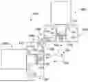
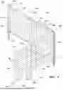

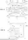

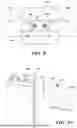
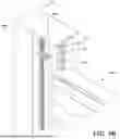
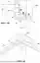
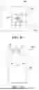


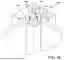


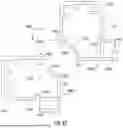


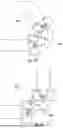
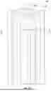


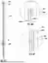
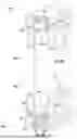

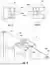
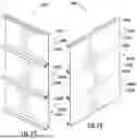
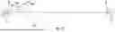
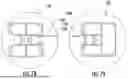
Sources:
- United States Patent and Trademark Office - verify current appl. status at the USPTO↗
Recent applications in this class:
- » 20260015886 2026-01-15
RACKABLE GATE KIT - » 20250223830 2025-07-10
TELESCOPIC PARTITION - » 20240368915 2024-11-07
RACKABLE PANEL ASSEMBLY AND METHODS OF ASSEMBLY THEREOF - » 20240344352 2024-10-17
ADAPTABLE FENCE BRACING - » 20240271460 2024-08-15
ADAPTABLE FENCE BRACING - » 20240141681 2024-05-02
RACKABLE GATE KIT - » 20230417076 2023-12-28
DEPLOYABLE FENCE SYSTEM - » 20230358072 2023-11-09
Adaptable fence bracing - » 20230287704 2023-09-14
Height adjustable and detachable fence system - » 20230243180 2023-08-03
Adaptable fence bracing