SOLENOID ACTUATED GEARED LINEAR ACTUATOR
US20260146509A1
2026-05-28
18/960,076
2024-11-26
Smart Summary: A system is designed to work deep underground in a wellbore. It uses a solenoid that creates a pulse to move a shaft in a straight line. This movement is connected to a gearing mechanism that allows another shaft to rotate. The second shaft then changes the size of an opening, or orifice. Overall, the system converts electrical energy into mechanical movement to control the flow of materials. 🚀 TL;DR
Abstract:
A system positioned in a wellbore formed in a subsurface formation. The system comprises a first solenoid configured to generate a first solenoid actuation pulse in a first linear direction in response to the first solenoid being energized. The system comprises a first shaft configured to axially translate in the first linear direction with the first solenoid actuation pulse. The system comprises a first gearing mechanism coupled with the first shaft and configured to axially rotate in a first rotational direction with the first solenoid actuation pulse. The system comprises a second shaft configured to move via the first gearing mechanism and to modify an area of an orifice.
Applicant:
Interested in similar patents?
Get notified when new applications in this technology area are published.
Classification:
E21B34/12 » CPC main
Valve arrangements for boreholes or wells in wells operated by movement of casings or tubings
E21B34/066 » CPC further
Valve arrangements for boreholes or wells in wells electrically actuated
E21B2200/03 » CPC further
Special features related to earth drilling for obtaining oil, gas or water Valves operated by gear mechanisms, e.g. rack and pinion mechanisms
E21B2200/09 » CPC further
Special features related to earth drilling for obtaining oil, gas or water Detecting, eliminating, preventing liquid slugs in production pipes
E21B34/06 IPC
Valve arrangements for boreholes or wells in wells
Description
TECHNICAL FIELD
This disclosure relates generally to the field of hydrocarbon recovery operations and more particular to solenoid based actuation systems positioned downhole in a wellbore.
BACKGROUND
In hydrocarbon recovery operations, systems may be positioned downhole in a wellbore to assist in producing fluid to the surface. Such systems may need to be adjusted to optimize the fluid recovery. One such system may include one or more gas lift valves to inject gas into the fluid to reduce the hydrostatic pressure in the fluid column and increase the pressure differential between the reservoir and the surface. Traditional gas lift valves may include an orifice and a check valve in a side pocket mandrel of a tubular string. To change the area of the orifice, and hence the injection rate, the entire unit may need to be replaced. This may be done with intervention operations such as wireline or slickline and may as such require well intervention equipment to be present. In a subsea environment this can be expensive to mobilize and operate.
BRIEF DESCRIPTION OF THE DRAWINGS
Implementations of the disclosure may be better understood by referencing the accompanying drawings.
FIG. 1 is a diagrammatic illustration of an example well system, according to some implementations.
FIG. 2 is a block diagram of an example solenoid based actuation system, according to some implementation.
FIG. 3 is an illustration depicting an example solenoid based actuation system with a dual-ratchet mechanism, according to some implementations.
FIG. 4 is an illustration depicting an example shaft and runner of a solenoid based actuation system, according to some implementations.
FIGS. 5A-B are illustrations depicting an example runner of a solenoid based actuation system, according to some implementations.
FIG. 6 is an illustration depicting an example solenoid based actuation system with a ratchet wheel, according to some implementations.
FIG. 7 is an illustration of an example solenoid based actuation system with ballpoint pen mechanisms, according to some implementations.
FIG. 8 is an illustration depicting an example solenoid based actuation system with a stepping device, according to some implementations.
FIG. 9 is an illustration depicting an example solenoid based actuation system with a cam as a stepping device, according to some implementations.
FIG. 10 is an illustration depicting an example solenoid based actuation system with a ballpoint pen retract mechanism as a stepping device, according to some implementations.
FIG. 11 is a flowchart depicting example operations for operating a solenoid based actuation system, according to some implementations.
DESCRIPTION
The description that follows includes example systems, methods, techniques, and program flows that embody aspects of the disclosure. However, it is understood that this disclosure may be practiced without these specific details. For instance, this disclosure refers to configurations of solenoid based actuation systems configured to modify an orifice area of a gas lift valve. Aspects of this disclosure can also be applied to any other translatable downhole device in a wellbore. For clarity, some well-known instruction instances, protocols, structures, and operations have been omitted.
Example implementations relate to a solenoid based actuation system positioned downhole in a wellbore and configured to modify a device. Devices positioned in a wellbore, such gas lift valves, may need to be altered. For example, as a well is produced and the reservoir is depleted, reservoir pressure may decrease over time and thus, not provide enough pressure to lift the fluid to the surface to be produced. Accordingly, one or more gas lift valves may be positioned in the wellbore such that gas may be injected into the fluid column to reduce the hydrostatic pressure of the fluid column and generate a greater pressure differential between the reservoir pressure and the surface pressure. Over time, the injection rate may be altered to accommodate for changing downhole pressures. This may be done by altering the area of the orifice in the gas lift valve. In conventional operations, the entire mandrel comprising the gas lift valve may need to be removed from the wellbore to be adjusted, replaced, etc., which may be expensive and result in a loss in production. In some implementations, one or more solenoids (such as electromagnetic solenoids) may be employed to modify the mechanism. However, due to the nature of a downhole environment (such as differential pressure between the tubing and the annular), the force required to move the needle valve and alter the orifice area may be considerable. Additionally, the electrical power supplied downhole may be limited, limiting the solenoids ability to modify the mechanism given the downhole environment. Moreover, due to the nature of solenoid configurations (i.e., only able to advance or retract a mechanism), the positions of the mechanisms may be limited. For instance, two solenoids may be employed to adjust an area of an orifice. One solenoid may reduce the area of the orifice to its minimum area (i.e., sealed shut), and the other solenoid may increase the area of the orifice to its maximum area (i.e., wide open). The solenoids may not allow for any alternate positions of the mechanism, such as having an area in between being fully closed and fully open. Additionally, the sudden moves on the valves while gas lift is in operation may cause effects like water hammer and slugging. Thus, in some implementations a solenoid based actuation system may be configured to modify a device such that solenoids may function as the primary movers but also the system allows for more than two possible positions and the modifications may be applied without wellbore intervention. Additionally, the configuration of the solenoid based actuation system may allow for the device to gradually move over a longer time to allow for smoother changes in operation and prevent effects such as water hammering and slugging.
In some implementations, a solenoid based actuation system may be configured with two solenoids to move an output shaft and modify a device, such as a conical needle to adjust the area of an orifice in a gas lift valve. The solenoid based actuation system may include a shaft configured to axially translate in both linear directions along the longitudinal axis of the system. A solenoid, when energized, may be actuated, contacting the shaft to axially translate the shaft in a first linear direction a fixed distance. A gearing mechanism coupled with the shaft may be configured to axially rotate about the longitudinal axis of the solenoid based actuation system. When the shaft axially translates, the gearing mechanism may axially rotate in the a first rotational direction. Subsequently, another shaft coupled with the gearing mechanism (such as an output axle), may rotate in the first rotational direction. Thus, the linear motion of the solenoid may be transformed to rotational motion, via the shafts and gearing mechanism of the solenoid based actuation system. The output axle may be coupled with device that is to be modified, such as a conical needle valve. For example, when the output axle rotates a fixed distance in the first rotational direction, components of the needle valve may also be rotated such that the conical needle moves a fixed distance in a linear direction, modifying the area of the orifice.
A second solenoid may be configured to be actuated, when energized, in the opposite direction of the other solenoid such that the components of the solenoid based actuation system move in the opposite direction as when the first solenoid is activated and thus the device is modified in the opposite direction. For example, the second solenoid may actuate, resulting in shaft linearly translating in a second linear direction that is opposite the first linear direction. Accordingly, the gearing mechanism may rotate in a second rotational direction opposite the first rotational direction, the output axle may rotate in the second rotational direction opposite the first rotational direction, and the needle valve to axially rotate in the opposite direction such that the conical needle axially translates in the opposite direction a fixed distance, modifying the orifice area. Thus, to multiply the available solenoid force, a gearing mechanism is used. Each actuation pulse of a solenoid advances or retracts (depending on which solenoid may be activated) the device (such as a conical needle) a fixed distance, regardless of the activation time. A high gearing ratio may also effectively lock the output of the solenoid based actuation system between actuations since the moment of inertia increases with the square of the gearing ratio. For large gearing ratios the force required to turn the first stage mechanism may be greater than the mechanical strength of the last gear stage.
In some implementations, the solenoid based actuation system may be configured with a stepping mechanism such that only a single solenoid is used as the primary mover. With the stepping mechanism, the actuation of the single solenoid may advance a device in a linear direction (such as a conical needle) to reduce the area of the orifice, rather than through a rotary-to-linear motion transformation, as described above. For example, a shaft may be coupled to a stepping mechanism, where the stepping mechanism is configured with a fixed number of steps. When the solenoid is energized, the shaft axially translates in a first linear direction, thus causing the stepping mechanism to advance to the next step (by either rotation and/or linear translation). As the stepping mechanism advances to the next step, an output shaft coupled with the stepping mechanism linearly translates a fixed distance in the first linear direction. In some implementations, the output shaft may be configured with and/or coupled with a conical needle that modifies the area of the orifice. When the device reaches the end of travel (e.g., the conical needle has fulling closed the orifice), the stepping mechanism may be configured such that the following pulse of the solenoid may return the needle to the other extreme position (e.g., the conical needle has fully opened the orifice area), or the needle begins to axially translate in the opposite linear direction. In some implementations, the stepping mechanism is used to drive a rotating device with a track, a cam or similar mechanisms that drive the needle in both extending and retracting directions.
In some implementations, the position of the device may be provided by a count in actuations of the solenoids. Reference position detection can be by means of a proximity sensor or an open/closed circuit detector, or by a simple homing sequence where the maximum number of activation pulses may be applied in one direction to ensure the stroke is at one extreme. After this homing sequence, knowing the position may be a simple matter of counting actuation pulses.
Example System
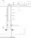
FIG. 1 is a diagrammatic illustration of an example well system, according to some implementations. In particular, a well system 100 of FIG. 1 includes a wellbore 102 in a subsurface formation 101. The wellbore 102 includes casing 104 and number of perforations 116 being made in the casing 104. The perforations 116 are located in a reservoir 132 to allow reservoir fluids (i.e., oil, water, and gas) from the reservoir 132 to flow into the wellbore 102 and into the tubular string 106 (the production tubing). The tubular string 106 includes a packer 112 that may prevent the comingling of fluids produced from the reservoir 132 and fluids in the annulus between the casing 104 and the tubular string 106. Additionally, the packer 112 may force the fluid produced from the reservoir 132 to flow to the surface 111 via the tubular string 106.
In some implementations, one or more gas lift mandrels, such as gas lift mandrel 108, may be integrated into the tubular string 106. The gas lift mandrel 108 may be configured with components such as a check valve, an orifice, etc. such that gas may be injected from the annulus and into the fluid within the tubular string 106 to assist in producing the fluid to the surface 111. In some implementations, the gas lift mandrel 108 may be configured with a solenoid based actuation system to alter the area of the orifice and thus adjust the injection rate into the tubular string. A conduit 110 may house one or more cables to supply power and/or communications to the solenoid based actuation system from a power source at or near the surface 111.
A flowline 120 coupled to the wellhead 118 of wellbore 102 and a separator 122 may allow the fluid produced up the tubular string 106 to flow to the separator 122. The separator 22 may be designed to separate the phases of the fluid produced from the wellbore 102. For instance, oil, water, and gas may be separated from each other after passing through the separator 122. The aggregate of fluid produced from wellbore 102 may then flow to a tank battery, via flowline 124, that may include components such as storage tank 126, to store the produced fluid.
The well system 100 of FIG. 1 depicts an example wellbore where a solenoid based actuation system may be positioned. The solenoid based actuation system described herein may be positioned in any suitable wellbore configurations and/or environment where alteration of a translatable mechanism may be useful (e.g., other flow control systems such as an inflow control device).
FIG. 2 is a block diagram of an example solenoid based actuation system, according to some implementation. In particular, FIG. 2 includes a block diagram 200 of a solenoid based actuation system 202 configured to convert linear motion to rotary motion between the solenoids 206 and the gearing 210. To allow for the use of small solenoids (to fit the required form factor given the area limitations in a wellbore and power budget) the motion may be geared at a significant ratio. This ratio, combined with the required total motion, may be relatively easy to achieve with rotary motion gearing, as shown in the block diagram 200. The solenoid based actuation system 202 may be positioned in a wellbore, such as in a gas lift mandrel as described in FIG. 1, and configured to modify a device (such as a needle valve and orifice). A power source 204 may supply power to the solenoid based actuation system 202. The power source may be external to the solenoid based actuation system 202. For example, the power source may be positioned at the surface, integrated into another component in the wellbore (such as a generator), etc.
The solenoids 206, when energized, may actuate a linear motion such that a shaft axially translates along the longitudinal axis of the solenoid based actuation system 202. Linear to rotary conversion 208 may be achieved via the gearing 210. For example, the linear translation of the shaft (actuated by the solenoids 206) may cause a gearing mechanism to axially rotate, thus converting the linear motion to rotary motion via the gearing 210. Additionally, rotary to linear motion 212 may be achieved via the gearing 210 and an output shaft 214. The output shaft 214 may be coupled with the gearing mechanism and may be configured to axially translate when the gearing mechanism axially rotates, thus converting the rotary motion to linear motion via the gearing 210. Example configurations of the solenoid based actuation system 202 are further described below.
Example Solenoid Based Actuation System
Example configurations of a solenoid based actuation system are now described. FIGS. 3-7 are example solenoid based actuation systems utilizing two or more solenoids as the primary movers. FIGS. 8-10 are example solenoid based actuation systems utilizing one solenoid as the primary mover. The solenoid based actuation systems are described in reference to the gas lift mandrel 108 of FIG. 1 and the block diagram 200 or FIG. 2.
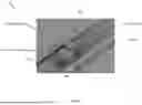
FIG. 3 is an illustration depicting an example solenoid based actuation system with a dual-ratchet mechanism, according to some implementations. In particular, FIG. 3 includes a solenoid based actuation system 300 configured with a shaft 302, a runner 306, and an output shaft 304. In some implementations, the shaft 302 may be free to axially translate along the longitudinal axis of the solenoid based actuation system 300 but may not rotate, the runner 306 may be free to both axially translate and axially rotate about the longitudinal axis of the solenoid based actuation system 300, and the output shaft 304 may axially rotate about the longitudinal axis of the solenoid based actuation system 300 but not axially translate.
Two solenoids (not pictured) may be paired in a back-to-back configuration. When the first solenoid is energized, a component (such as a shaft) is actuated in a linear direction and then returns to the initial position when the solenoid is deenergized. When the other solenoid is energized, a component (such as a shaft) of the other solenoid is actuated in a linear direction that is opposite the first solenoid, and then returns to the initial position when the solenoid is deenergized.
The shaft 302 may be configured with one or more treads that may spiral along a portion of the shaft 302. The runner 306 may be configured with one or more pins to engage with the slots (as shown in FIG. 4). When the first solenoid is energized, the solenoid may contact the shaft 302 such that the shaft 302 may axially translate a fixed distance. The runner 306 may axially translate until the teeth of the runner contact a face of the output shaft 304 with mating teeth and lock rotationally. The centering springs 310, 312 may ensure the runner 306 engages with the output shaft 304. After contacting the output shaft 304 as the shaft 302 continues to axially translate (via the actuation pulse of the first solenoid), the output shaft 304 may axially rotate at least a fraction of a revolution due to the runner 306 being locked to the shaft 302 and unable to rotate. The pins on the inside of the runner 306 may function as a cam mechanism to rotate the runner 306 and thus the output shaft 304. The distal end 308 of the output shaft 304 may be coupled with a device, such as a needle valve. For example, when the output shaft 304 is rotated during the actuation pulse of the solenoid, the needle valve may also rotate to modify the area of an orifice. When the solenoid is deenergized, centering springs 310, 312 may return the runner 306 to neutral (middle position) when the shaft 302 returns to the start position such that the teeth of the runner 306 may not be contacting the output shaft 304 (as shown in FIG. 5B), and a new cycle may begin. Due to no opposing force on the output shaft 304, the output shaft may not rotate in the opposite direction when the solenoid is deenergized. In some implementations, a face 314 of the output shaft 304 may be configured with grooves or any other suitable mechanisms to interact with components (such as a ball and spring) to prevent the output shaft 304 from rotating the opposite direction when the solenoid is deenergized if there are any external forces on the output shaft 304. Energizing the opposing solenoid may cause the shaft 302 to move in the opposite linear direction. Accordingly, the opposite face of the runner 306 may engage with the output shaft 304, causing the output shaft 304 to rotate the opposite rotational direction and the runner 306 engages with the treads on the shaft 302.
The teeth on the runner 306 and faces of the output shaft 304 may be formed as a sawtooth ramp, with one steep side for transfer of forces during the power stroke of the solenoid and on shallow side for low friction and reduced risk of binding on the return/relaxation stroke. In some implementations, the runner 306 may be configured as more than one piece. For example, the runner 306 may also be two separate halves activated by two independent solenoids if space and form factor permit so.
By correctly dimensioning the output shaft 304 groove pitch, the solenoid stroke length, and number of teeth on the runner 306 and output shaft 304, the output shaft 304 may approximately always move a fixed rotational distance (i.e., a given fraction of a full rotation) for each activation pulse, in that respect mimicking the operation of an electric stepper motor. Accordingly, the device coupled with the output shaft 304 to also rotate a fixed rotational distance with each activation pulse. This may allow for position to be tracked by the simple process of counting activation pulses up and down once the position is known. For example, an activation pulse of the solenoid may axially translate the conical needle of the needle valve approximately 1/100 millimeter (mm), 1/10 mm, 1 mm, etc. in a linear direction. Alternatively, the activation of the opposing solenoid may translate the conical needle 1 mm in the opposite direction. The solenoid based actuation system 300 may be configured to rotate the output shaft 304 any suitable distance to axially translate a component any suitable distance.
In some implementations, the components of the solenoid based actuation system 300 may be used in different configurations. For example, the shaft 302 and the output shaft 304 may be switched such that the shaft 302 may be free to axially rotate and function as the output to rotate a device (such as a needle valve) and the output shaft 304 may only be allowed to axially translate and move in a linear direction via the solenoids. Any suitable configuration of components for the solenoid based actuation system 300 may be utilized to generate initial rotary motion from two individual or coupled solenoid motions. The suitability of each approach may depend on if the entire mechanism must reside inside a single tubular housing or if other shapes can be used. In some implementations, the configuration of the components may depend on the materials of the components. For example, a configuration of components and their respective functions (such as which shaft may function as the output shaft) may be selected based on moving mass of each component, resulting in less moving mass and thus potentially faster operations for a given power budget.
FIG. 4 is an illustration depicting an example shaft and runner of a solenoid based actuation system, according to some implementations. In particular, FIG. 4 includes a shaft 402 and a runner 406. The shaft 402 may be similar to the shaft 302 depicted in FIG. 3. Similarly, the runner 406 may be similar to the runner 306 depicted in FIG. 3. A portion of the shaft 402 is configured to fit through a center bore of the runner 406 such that the runner 406 may translate along the shaft 402. The shaft may include treads in a spiral pattern around at least a portion of the shaft 402, such as tread 404. The runner 406 may be configured with one or more pins to engage with the tread 404. When the runner 406 translates along the shaft 402, the pin-tread interaction may cause the runner 406 to rotate as it translates along the shaft 402.
FIGS. 5A-B are illustrations depicting an example runner of a solenoid based actuation system, according to some implementations. In particular, FIG. 5A includes a side view of a runner 500. The runner 500 may be similar to the runner 306 and runner 406 depicted in FIGS. 3 and 4, respectively. The runner 500 may include one or pins 504, 506 on the face of the inner bore 502 that engage with treads on a shaft.
FIG. 5B includes a runner 524 between the mating faces of a shaft, such as the output shaft 304 described in FIG. 3. The shaft shown in FIG. 5A is depicted as two separate components (first end 520 and second end 522). In some implementations, the shaft may be one single component with a groove in which the runner 524 may be positioned in and may interact with (as depicted in FIG. 3). The first end 520 of the shaft includes a mating face 510 with teeth configured in one direction. The face 508A of the runner 524 includes teeth configured in the opposite direction as the mating face 510 so the teeth from both faces may engage and lock when the runner 524 translates towards the first end 520 (or when the first end translates towards the runner 524). Similarly, The second end 522 of the shaft includes a mating face 512 with teeth configured in one direction. The face 508B of the runner 524 includes teeth configured in the opposite direction as the mating face 512 so the teeth from both faces may engage and lock when the runner 524 translates towards the second end 522 (or when the first end translates towards the runner 524). When the runner 524 is in the neutral position (i.e., when no solenoids are energized and/or centralizing springs have returned the runner 524 to the neutral position), the faces 508A-B of the runner 524 may not be in contact with the mating faces 510, 512, respectively.
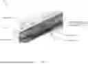
FIG. 6 is an illustration depicting an example solenoid based actuation system with a ratchet wheel, according to some implementations. In particular, FIG. 6 includes a solenoid based actuation system 600 configured with pins 604, 606, a ratchet wheel 608, a 90 degrees gear 610, and an output axle 612. The components of the solenoid based actuation system may be positioned in a tubular 602, such as a side pocket of a gas lift mandrel. The rotating motion will be around an axis perpendicular to the plane the solenoid pins may be in, so for a straight tubular enclosure a 90° gear may be used to move the axis of rotation.
Each pin 604, 606 may be coupled with a solenoid (not pictured), where the solenoids may be paired in a back-to-back configuration (similar to the solenoids described in FIG. 3). Similar to the interaction between the shaft 302 and the solenoid described in FIG. 3, when a first solenoid is energized, the pin 604 may axially translate in a first linear direction, pulling the ratchet wheel 608 to rotate the ratchet wheel 608.
With each actuation pulse of the solenoid, the pin 604 may pull through one tooth of rotation causing the ratchet to rotate. The 90 degree gear 610 coupled with the ratchet wheel 608 may also rotate with the ratchet wheel 608, resulting in the output axle 612 (coupled with the 90 degree gear 610) to also rotate. In some implementations, the pins 604, 606, ratchet wheel 608, and solenoids may be configured for the pins 604, 606 to push the ratchet wheel 608 to rotate the ratchet wheel 608.
In some implementations, the output axle may be similar to the output shaft 304 described in FIG. 3, where a device, such as a needle valve may be coupled with the output axle 612. Accordingly, when the output axle 612 rotates, then the needle valve may also rotate to modify the area of an orifice. When the other solenoid is energized, the actuation pulse may cause the ratchet wheel 608 to rotate in the opposite direction via the pulling of the pin 606, and thus the output axle 612 may rotate in the opposite direction.
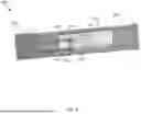
FIG. 7 is an illustration of an example solenoid based actuation system with ballpoint pen mechanisms, according to some implementations. In particular, FIG. 7 includes a solenoid based actuation system 700 configured with a forward ballpoint mechanism 704A, and a backward ballpoint mechanism 704B, and an output axle 712. Similar to the solenoid based actuation systems described in FIGS. 3-6, the output axle 712 may rotate through one step either forwards or backwards depending on which solenoid is actuated.
The forward ballpoint mechanism 704A and backward ballpoint mechanism 704B may be mounted back-to-back to form a slotted cylinder. The slotted cylinder may be free to axially translate and axially rotate when one of a pair of solenoids are actuated. Depending on the direction of movement on the slotted cylinder, the output axle may be turned through one step either linearly forwards or backwards. When a first solenoid is energized, a shaft 714 may axially translate in a first linear direction. The movement of the shaft may axially translate the slotted cylinder. A pin 706 fixed to the outer tubular via a plate 702 may engage with the tracks within the slotted cylinder such that when the slotted cylinder axially translates, the slotted cylinder is forced to axially rotate. The output axle 712 (and nut 708) may also rotate with the slotted cylinder. When the solenoid is deenergized, the centralizing spring 710 returns the slotted cylinder back to the neutral position. In some implementations, the output axle may be similar to the output shaft 304 described in FIG. 3, where a device, such as a needle valve may be coupled with the output axle 712. Accordingly, when the output axle 712 rotates, then the needle valve may also rotate, axially translating the conical needle a fixed distance to modify the area of an orifice. When the other solenoid is energized, the shaft 714 may be axially translated in the opposite direction and thus, the output axle 712 may axially rotate in the opposite direction via the slotted cylinder.
Solenoid based actuation systems utilizing one solenoid as the primary mover are now described. The solenoid based actuation systems described herein comprise a stepping device (derived from a ballpoint pen retract mechanism) that may be operated by the solenoid to axially translate a component a fixed distance with each actuation pulse. The number of steps of the stepping device may be tailored to the application, such as 4-6 steps plus a home position. The axial translation of a member via the solenoid and stepping device may axially translate a device, such as a conical needle such that the orifice area may be modified with each step. The taper angle of the conical needle and the stroke between positions may determine the orifice area range available.
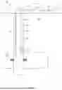
FIG. 8 is an illustration depicting an example solenoid based actuation system with a stepping device, according to some implementations. In particular, FIG. 8 includes a solenoid based actuation system 800 configured with a channel 806, a stepping device 804, and an actuator 802. The stepping device 804 is positioned within the channel 806 and the channel 806 is configured to allow the stepping device 804 to translate back and forth within the channel 806. The actuator 802 is configured with an arm 808 that may engage with the track 814 and return track 816 on the stepping device 804. The actuator 802 may be configured to axially translate forward a fixed distance when the solenoid is energized, and may return to an initial position (e.g., via a spring) when the solenoid is deenergized.
A solenoid (not pictured), when energized, may contact the actuator 802 to axial translate the actuator 802 in a linear direction. For example, the solenoid may push the actuator 802 a fixed distance into the channel 806. When the actuator 802 advances forward, the arm 808 (contacting the track 814 of the stepping device 804) may push the stepping device 804 forward in the same linear direction. Concurrently, the tooth of the arm 812 (which may be fixed to the channel 806) may advance to the next step in the track 818 of the stepping device 804 as the stepping device 804 axially translates forward, thus maintaining the position of the stepping device 804 in the channel 806 with the actuation pulse of the solenoid. An output shaft (not pictured) may extend from the stepping device 804 that is opposite the actuator 802. When the stepping device 804 axially translates with the actuation pulse of the solenoid, the output shaft may also axially translate in the same direction a fixed distance. In some implementations, a device, such as a conical needle, may be positioned at/or near the end of the output shaft. As the output shaft/conical needle translates, the area of an orifice proximate the conical needle may be modified (i.e., increased, decreased, sealed shut, etc.). For example, the conical needle may translate a fixed distance forward a number of steps (with each actuation pulse) until the orifice area may be sealed shut and/or the stepping device 804 returns to the home position, increasing the orifice area. Since the stepping mechanisms of the stepping device 804 may require the output shaft and conical needle to move forwards beyond the stationary position for every step, a reverse taper needle may be utilized if a sealing function is needed. When a fully closed position is not needed, a normal tapered needle may be used. If the orifice only has to be closed but not gas tight, a needle with a cylindrical cross section behind the taper with a close fit to the orifice may be used. The fully closed position may then have room to move forwards to advance the stepping device 804.
When the actuator 802 has reached the last step in the track 814, the actuator 802 may not translate any further in that direction due to the configuration of the track 814. Accordingly, the track 814 may be configured such that in the proceeding actuation pulse of the solenoid, the actuator 802 may return to the home position (i.e., translate in the opposite direction as when the solenoid advances the actuator 802). To do so, the arm 808 slides to the return track 816 of the track 814 with an actuation pulse. This may cause the arm 808 to apply a force to the extension 810 of the arm 812, causing the tooth of the arm 812 to disengage with the track 818. A bias component such as one or more springs (not pictured) may be positioned between the channel 806 and the stepping device 804 and configured to be bias towards the opposing direction as the solenoid actuation direction. When the arm 812 is disengaged with the track 818, the bias component may force the stepping device 804 back to the home position. Accordingly, the output shaft also moves back with the stepping device 804. If a conical needle is positioned at the end of the output shaft, the conical needle may translate in the opposite direction to increase the area of the orifice. Alternatively, a second transfer mechanism like a track or a cam may be used to remove the needle for the reverse taper. This may also be done by using a spring between the solenoid based actuation system 800 and the valve needle.
Any suitable device and/or method may be utilized for determining the position of the stepping device 804. A home position sensing circuit may be with a hall or gear tooth solid state sensor if the temperature rating of the sensing device allows. Other alternatives may include the needle valve closing an electrical circuit, a magnet activated proximity switch, etc. Giving the home position a different stroke length than the other positions (i.e., when the arm 812 is disengaged from the track 818 to return to the home position) may enable detection through the shape and duration of the solenoid current.
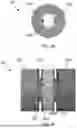
FIG. 9 is an illustration depicting an example solenoid based actuation system with a cam as a stepping device, according to some implementations. In particular, FIG. 9 includes a solenoid based actuation system 900 configured with a shaft 904, a cam 908, and an output shaft 912 all positioned on a frame 902. Similar to FIG. 8, a single solenoid (not pictured) may function as the primary mover for the solenoid based actuation system 900.
When the solenoid is energized, the actuation pulse may actuate the shaft 904 to axially translate a fixed distance in a linear direction. The axial translation of the shaft 904 may engage with a tooth of a gearing mechanism 906 to rotate the gearing mechanism one step (i.e., one tooth). A pin 910 may prevent the gearing mechanism from rotating in the opposite direction. A cam 908 may be coupled with the gearing mechanism 906 and may rotate with the gearing mechanism 906. The cam 908 may be any suitable shape and/or be in any suitable position on the gearing mechanism. An output shaft 912 may be positioned proximate the cam 908 such that the output shaft 912 axially translates a fixed distance when the cam 908 rotates a step with the actuation pulse of the solenoid. Similar to the solenoid based actuation system described in FIG. 8, a device may be positioned at/near the end of the shaft to modify the area of an orifice as the shaft translates back and forth.
Starting at a home position (e.g., the output shaft 912 is positioned all the way back and the orifice area is 100% open), the solenoid may be energized a number of times to cycle the gearing mechanism 906 and cam 908 to move the output shaft forward in a linear direction. In some implementations, the components of the solenoid based actuation system 900 may be configured such that when the output shaft in fully forward, the needle may fully seal the orifice. As the gearing mechanism 906 and cam 908 continue to cycle with each actuation pulse, the output shaft may then translate in the opposite direction until it returns to the home position.
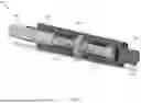
FIG. 10 is an illustration depicting an example solenoid based actuation system with a ballpoint pen retract mechanism as a stepping device, according to some implementations. In particular, FIG. 10 includes a solenoid based actuation system 1000 configured with a shaft 1004, a rotating cylinder 1008 with a track 1010, a cam track 1014, and an output shaft 1016. Similar to FIG. 8, a single solenoid (not pictured) may function as the primary mover for the solenoid based actuation system 1000.
When the solenoid is energized, the actuation pulse may actuate the shaft 1004 to axially translate a fixed distance in a linear direction along the longitudinal axis. The axial translation of the shaft 1004 may cause a pin on an actuator 1006 to engage with a track 1010 on a rotating cylinder 1008. The rotating cylinder 1008 may be similar to a ballpoint pen retract mechanism where the rotating cylinder 1008 may rotate a fixed distance with each actuation pulse of the solenoid. A cylindrical cam 1012 configured with a cam track 1014 maybe coupled with the rotating cylinder 1008 such that the cylindrical cam 1012 may rotate with the rotating cylinder 1008. An output shaft 1016 may be coupled with the cylindrical cam 1012. The output shaft 1016 may be configured with one or more pins that engage with the cam track 1014 such that the output shaft may axially translate a fixed distance in a linear direction as the cylindrical cam 1012 with each actuation pulse of the solenoid. Similar to the solenoid based actuation system 800 described in FIG. 8, a device 1020 may be positioned at/near the end of the output shaft 1016 to modify the area of an orifice as the output shaft 1016 translates with each actuation pulse of the solenoid.
Example Operations
Examples operations are now described.
FIG. 11 is a flowchart depicting example operations for operating a solenoid based actuation system, according to some implementations. FIG. 11 depicts a flowchart 1100 for modifying a downhole device (such the orifice area of a gas lift valve) with a system that uses solenoids as the primary movers with more than two possible positions. The operations of flowchart 1100 are described in reference to the solenoid based actuation system described in FIGS. 2-10.
At block 1102, a first solenoid positioned in a wellbore formed in a subsurface formation may be energized to generate a first solenoid actuation pulse in a first linear direction.
At block 1104, a first shaft may be axially translated in the first linear direction with the first solenoid actuation pulse.
At block 1106, a first gearing mechanism may be axially rotated in a first rotational direction with the first solenoid actuation pulse, wherein the first gearing mechanism is coupled with the first shaft.
At block 1108, a second shaft may be moved via the first gearing mechanism to modify an area of an orifice.
While the aspects of the disclosure are described with reference to various implementations and exploitations, it will be understood that these aspects are illustrative and that the scope of the claims is not limited to them. In general, techniques for configuring a solenoid based actuation system as described herein may be implemented with facilities consistent with any hardware system or hardware systems. Many variations, modifications, additions, and improvements are possible.
Plural instances may be provided for components, operations or structures described herein as a single instance. Finally, boundaries between various components, operations and data stores are somewhat arbitrary, and particular operations are illustrated in the context of specific illustrative configurations. Other allocations of functionality are envisioned and may fall within the scope of the disclosure. In general, structures and functionality presented as separate components in the example configurations may be implemented as a combined structure or component. Similarly, structures and functionality presented as a single component may be implemented as separate components. These and other variations, modifications, additions, and improvements may fall within the scope of the disclosure.
Various modifications to the implementations described in this disclosure may be readily apparent to those skilled in the art, and the generic principles defined herein may be applied to other implementations without departing from the spirit or scope of this disclosure. Thus, the claims are not intended to be limited to the implementations shown herein but are to be accorded the widest scope consistent with this disclosure, the principles and the novel features disclosed herein.
Certain features that are described in this specification in the context of separate implementations also may be implemented in combination in a single implementation. Conversely, various features that are described in the context of a single implementation also may be implemented in multiple implementations separately or in any suitable subcombination. Moreover, although features may be described as acting in certain combinations and even initially claimed as such, one or more features from a claimed combination may in some cases be excised from the combination, and the claimed combination may be directed to a subcombination or variation of a subcombination.
Similarly, while operations are depicted in the drawings in a particular order, this should not be understood as requiring that such operations be performed in the particular order shown or in sequential order, or that all illustrated operations be performed, to achieve desirable results. Further, the drawings may schematically depict one more example process in the form of a flow diagram. However, some operations may be omitted and/or other operations that are not depicted may be incorporated in the example processes that are schematically illustrated. For example, one or more additional operations may be performed before, after, simultaneously, or between any of the illustrated operations. In certain circumstances, multitasking and parallel processing may be advantageous. Moreover, the separation of various system components in the implementations described should not be understood as requiring such separation in all implementations, and the described program components and systems may generally be integrated together in a single software product or packaged into multiple software products. Additionally, other implementations are within the scope of the following claims. In some cases, the actions recited in the claims may be performed in a different order and still achieve desirable results.
Unless otherwise specified, use of the terms “up,” “upper,” “upward,” “uphole,” “upstream,” or other like terms shall be construed as generally away from the bottom, terminal end of a well; likewise, use of the terms “down,” “lower,” “downward,” “downhole,” or other like terms shall be construed as generally toward the bottom, terminal end of the well, regardless of the wellbore orientation. Use of any one or more of the foregoing terms shall not be construed as denoting positions along a perfectly vertical axis. In some instances, a part near the end of the well can be horizontal or even slightly directed upwards. Unless otherwise specified, use of the term “subsurface formation” shall be construed as encompassing both areas below exposed earth and areas below earth covered by water such as ocean or fresh water.
Example Implementations
Implementation #1: A system positioned in a wellbore formed in a subsurface formation comprising: a first solenoid configured to generate a first solenoid actuation pulse in a first linear direction in response to the first solenoid being energized; a first shaft configured to axially translate in the first linear direction with the first solenoid actuation pulse; a first gearing mechanism coupled with the first shaft and configured to axially rotate in a first rotational direction with the first solenoid actuation pulse; and a second shaft configured to move via the first gearing mechanism and to modify an area of an orifice.
Implementation #2: The system of Implementation #1, wherein the second shaft is configured to move via the first gearing mechanism in the first rotational direction.
Implementation #3: The system of Implementation #2, wherein the second shaft is coupled with a needle valve, and wherein the area of the orifice is modified via the needle valve.
Implementation #4: The system of any one or more of Implementation #1-3 further comprising: one or more springs coupled with the first shaft and configured to return the first gearing mechanism to a neutral position when the first solenoid is deenergized.
Implementation #5: The system of any one or more of Implementation #1-4 further comprising: a second solenoid configured to generate a second solenoid actuation pulse in a second linear direction that is opposite the first linear direction when the second solenoid is energized, wherein the first shaft is configured to axially translate in the second linear direction with the second solenoid actuation pulse.
Implementation #6: The system of Implementation #5, wherein the first gearing mechanism is configured to axially rotate in a second rotational direction with the second solenoid actuation pulse, and wherein the second shaft is configured to move via the first gearing mechanism in the second rotational direction.
Implementation #7: The system of Implementation #5 or #6, wherein the second shaft is configured to axially rotate in a second rotational direction that is opposite the first rotational direction, via the first gearing mechanism, when the first shaft axially translates in the second linear direction.
Implementation #8: The system of any one or more of Implementation #1-7, wherein the second shaft is configured to move a fixed distance with the first solenoid actuation pulse.
Implementation #9: The system of any one or more of Implementation #1-8, wherein the first gearing mechanism includes a stepping device, and wherein the second shaft is configured to axially translate in the first linear direction via the stepping device and modify the area of the orifice.
Implementation #10: The system of Implementation #9, wherein the second shaft is configured to return to an initial position that after a fixed number of actuation pulses of the first solenoid.
Implementation #11: An apparatus comprising: a first shaft configured to axially translate in a first linear direction via a first solenoid, wherein the first solenoid is configured to generate a first solenoid actuation pulse in the first linear direction in response to the first solenoid being energized; a first gearing mechanism coupled with the first shaft and configured to axially rotate in a first rotational direction with the first solenoid actuation pulse; and a second shaft configured to move via the first gearing mechanism and to modify an area of an orifice.
Implementation #12: The apparatus of Implementation #11 wherein the second shaft is configured to move via the first gearing mechanism in the first rotational direction.
Implementation #13: The apparatus of Implementation #12, wherein the second shaft is coupled with a needle valve, and wherein the area of the orifice is modified via the needle valve.
Implementation #14: The apparatus of any one or more of Implementation #11-13 further comprising: a second solenoid configured to generate a second solenoid actuation pulse in a second linear direction that is opposite the first linear direction when the second solenoid is energized, wherein the first shaft is configured to axially translate in the second linear direction with the second solenoid actuation pulse.
Implementation #15: The apparatus of Implementation #14, wherein the first gearing mechanism is configured to axially rotate in a second rotational direction with the second solenoid actuation pulse, and wherein the second shaft is configured to move via the first gearing mechanism in the second rotational direction.
Implementation #16: The apparatus of Implementation #14, wherein the second shaft is configured to axially rotate in a second rotational direction that is opposite the first rotational direction, via the first gearing mechanism, when the first shaft axially translates in the second linear direction.
Implementation #17: The apparatus of any one or more of Implementation #11-16, wherein the second shaft is configured to move a fixed distance with the first solenoid actuation pulse.
Implementation #18: A method comprising: energizing a first solenoid positioned in a wellbore formed in a subsurface formation to generate a first solenoid actuation pulse in a first linear direction; axially translating a first shaft in the first linear direction with the first solenoid actuation pulse; axially rotating a first gearing mechanism in a first rotational direction with the first solenoid actuation pulse, wherein the first gearing mechanism is coupled with the first shaft; and moving a second shaft via the first gearing mechanism to modify an area of an orifice.
Implementation #19: The method of Implementation #18 further comprising: energizing a second solenoid to generate a second solenoid actuation pulse in a second linear direction that is opposite the first linear direction; axially translating the first shaft in the second linear direction with the second solenoid actuation pulse; axially rotate the first gearing mechanism in a second rotational direction with the second solenoid actuation pulse; moving the second shaft via the first gearing mechanism in the second rotational direction to modify the area of the orifice.
Implementation #20: The method of Implementation #18 or #19, wherein the second shaft moves a fixed distance with the first solenoid actuation pulse.
Use of the phrase “at least one of” preceding a list with the conjunction “and” should not be treated as an exclusive list and should not be construed as a list of categories with one item from each category, unless specifically stated otherwise. A clause that recites “at least one of A, B, and C” can be infringed with only one of the listed items, multiple of the listed items, and one or more of the items in the list and another item not listed.
As used herein, the term “or” is inclusive unless otherwise explicitly noted. Thus, the phrase “at least one of A, B, or C” is satisfied by any element from the set {A, B, C} or any combination thereof, including multiples of any element.
Claims
1. A system positioned in a wellbore formed in a subsurface formation comprising:
a first solenoid configured to generate a first solenoid actuation pulse in a first linear direction in response to the first solenoid being energized;
a first shaft configured to axially translate in the first linear direction with the first solenoid actuation pulse;
a first gearing mechanism coupled with the first shaft and configured to axially rotate in a first rotational direction with the first solenoid actuation pulse; and
a second shaft configured to move via the first gearing mechanism and to modify an area of an orifice.
2. The system of claim 1 wherein the second shaft is configured to move via the first gearing mechanism in the first rotational direction.
3. The system of claim 2, wherein the second shaft is coupled with a needle valve, and wherein the area of the orifice is modified via the needle valve.
4. The system of claim 1 further comprising:
one or more springs coupled with the first shaft and configured to return the first gearing mechanism to a neutral position when the first solenoid is deenergized.
5. The system of claim 1 further comprising:
a second solenoid configured to generate a second solenoid actuation pulse in a second linear direction that is opposite the first linear direction when the second solenoid is energized, wherein the first shaft is configured to axially translate in the second linear direction with the second solenoid actuation pulse.
6. The system of claim 5, wherein the first gearing mechanism is configured to axially rotate in a second rotational direction with the second solenoid actuation pulse, and wherein the second shaft is configured to move via the first gearing mechanism in the second rotational direction.
7. The system of claim 5, wherein the second shaft is configured to axially rotate in a second rotational direction that is opposite the first rotational direction, via the first gearing mechanism, when the first shaft axially translates in the second linear direction.
8. The system of claim 1, wherein the second shaft is configured to move a fixed distance with the first solenoid actuation pulse.
9. The system of claim 1, wherein the first gearing mechanism includes a stepping device, and wherein the second shaft is configured to axially translate in the first linear direction via the stepping device and modify the area of the orifice.
10. The system of claim 9, wherein the second shaft is configured to return to an initial position that after a fixed number of actuation pulses of the first solenoid.
11. An apparatus comprising:
a first shaft configured to axially translate in a first linear direction via a first solenoid, wherein the first solenoid is configured to generate a first solenoid actuation pulse in the first linear direction in response to the first solenoid being energized;
a first gearing mechanism coupled with the first shaft and configured to axially rotate in a first rotational direction with the first solenoid actuation pulse; and
a second shaft configured to move via the first gearing mechanism and to modify an area of an orifice.
12. The apparatus of claim 11 wherein the second shaft is configured to move via the first gearing mechanism in the first rotational direction.
13. The apparatus of claim 12, wherein the second shaft is coupled with a needle valve, and wherein the area of the orifice is modified via the needle valve.
14. The apparatus of claim 11 further comprising:
a second solenoid configured to generate a second solenoid actuation pulse in a second linear direction that is opposite the first linear direction when the second solenoid is energized, wherein the first shaft is configured to axially translate in the second linear direction with the second solenoid actuation pulse.
15. The apparatus of claim 14, wherein the first gearing mechanism is configured to axially rotate in a second rotational direction with the second solenoid actuation pulse, and wherein the second shaft is configured to move via the first gearing mechanism in the second rotational direction.
16. The apparatus of claim 14, wherein the second shaft is configured to axially rotate in a second rotational direction that is opposite the first rotational direction, via the first gearing mechanism, when the first shaft axially translates in the second linear direction.
17. The apparatus of claim 11, wherein the second shaft is configured to move a fixed distance with the first solenoid actuation pulse.
18. A method comprising:
energizing a first solenoid positioned in a wellbore formed in a subsurface formation to generate a first solenoid actuation pulse in a first linear direction;
axially translating a first shaft in the first linear direction with the first solenoid actuation pulse;
axially rotating a first gearing mechanism in a first rotational direction with the first solenoid actuation pulse, wherein the first gearing mechanism is coupled with the first shaft; and
moving a second shaft via the first gearing mechanism to modify an area of an orifice.
19. The method of claim 18 further comprising:
energizing a second solenoid to generate a second solenoid actuation pulse in a second linear direction that is opposite the first linear direction;
axially translating the first shaft in the second linear direction with the second solenoid actuation pulse;
axially rotate the first gearing mechanism in a second rotational direction with the second solenoid actuation pulse;
moving the second shaft via the first gearing mechanism in the second rotational direction to modify the area of the orifice.
20. The method of claim 18, wherein the second shaft moves a fixed distance with the first solenoid actuation pulse.
Images & Drawings included:


Sources:
- United States Patent and Trademark Office - verify current appl. status at the USPTO↗
Recent applications in this class:
- » 20250297531 2025-09-25
SWIVEL AND CIRCULATION CONTROL VALVE TOOL - » 20250188818 2025-06-12
CURVED FLOW TUBE TO SLOW A CLOSURE OF A FLOW VALVE - » 20250084710 2025-03-13
COMPLETION STRING, METHOD, AND SYSTEM - » 20250027384 2025-01-23
Core Barrel Head Assembly - » 20240125202 2024-04-18
VALVE, METHOD, AND SYSTEM - » 20240102356 2024-03-28
Core barrel head assembly - » 20230383621 2023-11-30
Producing gas through variable bore production tubing - » 20230212925 2023-07-06
Pressure-activated valve assemblies and methods to remotely activate a valve - » 20230023843 2023-01-26
Mechanical drain for oilfield service - » 20220205338 2022-06-30
Subsurface safety valve with uniform loading