High Granularity Pump Maintenance for Split Flow Wellbore Services System
US20260146522A1
2026-05-28
19/367,546
2025-10-23
Smart Summary: A system is designed to pump fluids for well servicing using split flow technology. It consists of a trailer with separate lines for clean and dirty fluids, along with a high-pressure line. Each pumping unit has two pumps that can handle either clean or dirty fluids. Valves control the flow of fluids to each pump, allowing for flexibility in operation. The pumps can be switched between clean and dirty roles as needed, making maintenance easier and more efficient. 🚀 TL;DR
Abstract:
Disclosed embodiments include split flow pumping systems for providing well servicing fluid to a well, and methods of maintenance thereto. For example, the system can include a manifold trailer having a clean split flow line, a dirty split flow line, and a high-pressure manifold line; a plurality of pumping units disposed in proximity to the manifold trailer, each pumping unit comprising two pumps; and for each pump of each pumping unit, a clean flow valve configured to control flow from the clean split flow line to the corresponding pump, and a dirty flow valve configured to control flow from the dirty split flow line to the corresponding pump. In embodiments, one or both pumps of each pumping unit can be designated as clean, one or both pumps of each pumping unit can be designated as dirty, and/or each pump can be switched between clean and dirty designation.
Inventors:
- Bruce Carl Lucas 16 🇺🇸 Duncan, OK, United States
- Brad Bull 4 🇺🇸 Duncan, OK, United States
- Kalyb Beaver 2 🇺🇸 Duncan, OK, United States
Applicant:
Interested in similar patents?
Get notified when new applications in this technology area are published.
Classification:
E21B43/2607 » CPC main
Methods or apparatus for obtaining oil, gas, water, soluble or meltable materials or a slurry of minerals from wells; Methods for stimulating production by forming crevices or fractures Surface equipment specially adapted for fracturing operations
E21B43/26 IPC
Methods or apparatus for obtaining oil, gas, water, soluble or meltable materials or a slurry of minerals from wells; Methods for stimulating production by forming crevices or fractures
Description
CROSS-REFERENCE TO RELATED APPLICATIONS
This application is a continuation-in-part of and claims priority to U.S. patent application Ser. No. 18/958,190, filed Nov. 25, 2024, the entire contents of which are incorporated herein by reference.
FIELD
This disclosure relates generally to the field of pumping. More particularly, this disclosure relates to the field of pumping units. Still more particularly, this disclosure relates to a system and related methods allowing maintenance access to the pumps of pumping units in situ when connected to a pressurized manifold of a wellbore services system.
BACKGROUND
Conventional pumping units, such as those utilized for wellbore operations (e.g., for hydraulic fracking) typically are not serviced while the pump of the pumping unit is disposed in a “red zone” of pressurized wellbore services equipment. For example, a red zone may typically be a defined distance adjacent pressurized equipment. Accordingly, for maintenance to be performed, either the pumping unit as a whole may typically be removed from the red zone, or the job may be halted while maintenance is performed in situ. Either of these approaches can be a time-consuming operation, as the job must typically be halted for the time taken to rig down the unit or perform the maintenance. Furthermore, the delays inherent in such a system can negatively impact pumping efficiency of the wellbore services system. Thus, there is a need for improved techniques for safely performing maintenance on a pump of a pumping unit, for example to significantly reduce or eliminate job downtime due to pump maintenance.
BRIEF DESCRIPTION OF THE DRAWINGS
Embodiments of the disclosure may be better understood by referencing the accompanying drawings.
FIG. 1 is a schematic of an exemplary pumping unit, according to embodiments of this disclosure;
FIG. 2 is a schematic of an exemplary pump module, according to embodiments of this disclosure;
FIG. 3 is a schematic representation of an overview of an exemplary wellbore servicing system, according to embodiments of this disclosure;
FIG. 4 is a schematic of an exemplary wellbore services system, according to embodiments of this disclosure;
FIG. 5 is an isometric view of a portion of the wellbore services system of FIG. 4, according to embodiments of this disclosure;
FIG. 6 is an overhead plan view of a portion of the wellbore services system of FIG. 4, according to embodiments of this disclosure;
FIG. 7 is a schematic overhead plan view of a portion of the wellbore services system of FIG. 4, according to embodiments of this disclosure;
FIG. 8 is a schematic illustration of an exemplary split-flow wellbore services system, according to an embodiment of the disclosure;
FIG. 9 is a schematic illustration of a portion of another exemplary split-flow system, according to an embodiment of the disclosure;
FIG. 10 is a plan view of another exemplary system, according to an embodiment of the disclosure;
FIG. 11 is an isometric view of a portion of the system of FIG. 10, according to an embodiment of the disclosure;
FIG. 12 is a plan view of FIG. 11, according to an embodiment of the disclosure;
FIG. 13 is another isometric view similar to the system of FIG. 11, according to an embodiment of the disclosure;
FIGS. 14-15 are alternate isometric views showing aspects of the system of FIG. 11, according to an embodiment of the disclosure;
FIG. 16 is a plan view of a portion of the system of FIG. 10, according to an embodiment of the disclosure;
FIG. 17 is a partial isometric view of a similar wellbore servicing system, configured to allow for switching of individual pump designations on an exemplary pumping unit, according to an embodiment of the disclosure;
FIG. 18 is an enlarged view of a portion of the system of FIG. 17, illustrating exemplary clean and dirty flow valving, according to an embodiment of the disclosure; and
FIGS. 19A-D schematically illustrate how individual pumps of an exemplary pumping unit can be designated as either clean or dirty, for example with a first pump designated dirty and a second pump designated clean (see FIG. 19A), a first pump designated clean and a second pump designated dirty (see FIG. 19B), both pumps designated clean (see FIG. 19C), or both pumps designated dirty (see FIG. 19D), according to an embodiment of the disclosure.
DESCRIPTION
The description that follows includes example systems, methods, techniques, and program flows that embody aspects of the disclosure. However, it is understood that this disclosure may be practiced without these specific details. For brevity, well-known steps, protocols, structures, and techniques have not been shown in detail in order not to obfuscate the description.
As noted above, there is a need for improved techniques for safely performing maintenance on a pump of a pumping unit, for example to reduce downtime of the pump during maintenance. As disclosed herein, the use of shielding, in conjunction with remote isolation and de-pressurization of the pump, may allow for maintenance to be safely performed on the pump, for example on a fluid end of the pump, without the need to move the pump out of the red zone and/or while the wellbore services manifold trailer is pressurized (for example by other active pumps). Before discussing the specifics of such systems and methods for improved (e.g. in situ) maintenance in detail, exemplary pumping units, pumps, and wellbore services systems, of the sort that can be used in this system, will now be set forth.
FIG. 1 illustrates schematically an exemplary pumping unit 100. While the specific exemplary pumping unit 100 shown in FIG. 1 is configured for a modular approach (allowing modular pump removal and replacement), it should be understood that the maintenance system described herein can be used with various pumping units, whether modular or not. The pumping unit 100 of FIG. 1 can comprise a base structure 101; an electric motor 110 mounted on the base structure 101; and one or more pump modules 150. As depicted via brackets, in the embodiment of FIG. 1, the one or more pump modules 150 include two pump modules 150, comprising first pump module 150A and second pump module 150B. Each of the one or more pump modules 150 comprises a pump 120 and a pump module structure 130. The one or more pump modules 150 are configured to be removably mounted on the base structure 101 and driven by the electric motor 110.
The pumping unit 100 can further comprise at least one connector panel 102 comprising connectors 103 for electrical cables and/or hoses 104 from the one or more pump modules 150, wherein the electrical cables and/or hoses 104 are configured for supplying fluids, electric power, and/or control signals to the one or more pump modules 150, and/or to receive sensor feedback from the one or more pump modules 150. One or more of the connectors/receptacles 103 can be configured for providing/receiving electrical power to the connector panel 102.
The base structure 101 can comprise a truck, a trailer, or a skid. The electric motor 110, an electric motor drive 160 (which can include) an auxiliary electric power supply 107, or a combination thereof can be mounted on the base structure 101. A pump packing lubrication system 108 can be mounted on the base structure 101.
In embodiments, the base structure 101 can further comprise one or more mounting points/elements 115, and each of the one or more pump modules 150 can comprise one or more complementary mounting points/elements 116, configured such that each of the one or more mounting points 115 of the base structure 101 are configured to receive/align with one or more of the one or more complementary mounting elements 116 of the one or more pump modules 150, to position and/or align the pump module 150 (e.g., a driveline 135 thereof) with the electric motor 110 (e.g., with a motor shaft 111 thereof).
FIG. 2 is a schematic of an exemplary pump module 150, providing additional details about exemplary pumps 120. In embodiments, each of the one or more pump modules 150 can comprise the pump module structure 130, the pump 120, a driveline 135, and pump auxiliary systems 140. The pump auxiliary systems 140 can comprise an oil lubrication pump 141, an oil reservoir 143, one or more oil filters 144, an oil cooler 145, an oil heater 187, a sensor package 146 (e.g., comprising one or more sensors 147 for monitoring pressure, temperature, position), a driveline 135 (“driveshaft assembly”), or a combination thereof. The oil lubrication pump 141 can be powered by an auxiliary electric motor 142, in embodiments. Oil cooler 145 can comprise a heat exchanger (e.g., radiator having oil circulating therein) and a fan, in embodiments. The oil heater 187 can comprise a heat exchanger or heating element such as an electrical resistance heating element 188 disposed within the oil reservoir 143 or a heating jacket disposed around all or a portion of the oil reservoir 143. The oil cooler and/or heater can be controlled by control systems 153 responsive to temperature of the oil and/or ambient temperature sensed by one or more sensors of the sensor package 146. The pump auxiliary systems 140 can further comprise a suction manifold 148 and a discharge manifold 149 with connectors for piping, a pump packing lubrication system 151, a driveshaft clutch and/or driveshaft decoupler 152, electrical cables and/or hoses 104, control systems 153, or a combination thereof.
Each of the pump modules 150 can comprise cables and/or hoses 104 that extend to one or more connector panels 102 mounted on the base structure 101. For example, two connector panels 102 are depicted in the embodiments of FIG. 1. However, in embodiments, a single connector panel 102 can be utilized for one, two, or more pump modules 150, or a plurality of connector panels 102 can be associated with each pump module 150. In embodiments, connector panel 102 can be mounted on base structure 101 (rather than on pump module structure 130). One or more cables (e.g., electrical cables) and/or hoses 104 can connect the connector panel 102 with (e.g., components of) pump module 150. A receptacle/connector 103 of the connector panel 102 can receive electrical supply for the pumping unit 100.
Each of the one or more pump modules 150 can further comprise one or more lift components 113 configured for removal of each of the one or more pump modules 150 from the base structure 101. The lifting components 113 are not particularly limited, and can comprise, for example, one or more forklift pockets, lifting eyes, or a combination thereof.
As depicted in FIG. 2, each of the one or more pump modules 150 can further comprise guarding 114, such as configured for rotating or otherwise moving one or more components of the pump module 150; deflectors, trays, and/or tanks, such as for directing or containing fluids; or a combination thereof.
The electric motor 110 can comprise a first drive shaft 111A and a second drive shaft 111B. In such embodiments, as depicted in FIG. 1, the pumping unit 100 can comprise two pump modules 150, with a first pump module 150A and a second pump module 150B. First pump module 150A is connected to the first drive shaft 111A and second pump module 150B is connected to the second drive shaft 111B, whereby the two pump modules 150 can be driven by the single electric motor 110. The pumping unit 100 can be designed to operate with a single pump module 150 or more pump modules 150 (e.g., with exactly two pump modules 150).
As depicted in FIG. 2, each of the one or more pump modules 150 can further comprise a pump packing lubrication system 151a (e.g., a “packing grease system”), and/or can be connected to a remote pump packing grease system 151b, and have no fluid connections from the pump packing lubrication system 151 to the base structure 101.
One or more of the pump module(s) 150 can comprise a pump life monitoring system 154 that is operable to provide component identification, data processing, data storage and/or communications (e.g., internal and/or external), or a combination thereof. In this manner, life data for each pump module 150 can be monitored and tracked (e.g., independently of the life of a pumping unit 100 itself).
As noted herein, pump 120 of each pump module 150 can comprise a triplex or quintuplex plunger pump (e.g., positive displacement pump), in embodiments. Pump 120 of each of the one or more pump modules 150 can be mounted onto the pump module structure 130 of the each of the one or more pump modules 150 in a manner designed to reduce and/or prevent translation of flexure of the pump module structure 130 to the pump 120. For example, in embodiments, pump 120 of each of the one or more pump modules 150 can be mounted onto the pump module structure 130 of the each of the one or more pump modules 150 via a three-point mounting sub-structure 190 that reduces and/or prevents translation of flexure of the pump module structure 130 to the pump 120.
Additionally, or alternatively, pump 120 of one or more pump modules 150 can be a centrifugal pump. A centrifugal pump for pumping wellbore servicing fluids downhole comprises a housing having an inlet and an outlet, and a rotating impeller disposed within the housing. The impeller has a plurality of vanes extending radially outwardly from a central hub and is mounted on a shaft that is driven by the electric motor. The impeller rotates at high speed, creating a centrifugal force that propels the wellbore servicing fluid (e.g., fracturing fluid) through the pump and into the wellbore via a manifold and associate piping fluidically coupling the pump 120 to the wellbore.
Each of the one or more pump modules 150 is driven by the electric motor 110 via connection of a driveline 135 of each of the pump modules 150 with a shaft 111 of the electric motor 110. In embodiments, the driveline can comprise a driveshaft clutch and/or a driveshaft decoupler 152, whereby rotary motion can be prevented from being transmitted from the electric motor 110 to pump 120.
While the specific exemplary pumping units and/or pumps described herein may be in the context of an exemplary modular pumping unit, many of the same basic elements would be shared with conventional, non-modular pumping units, as persons of skill would understand. The discussion of exemplary pumping units is not intended to be limiting, but merely provides examples for context. The systems and method of improved pump maintenance described herein can apply to both modular and non-modular pumping units.
One or more pumping units 100 can be used within a wellbore servicing system 200. An embodiment of a wellbore servicing system 200 and a method of servicing a wellbore via the wellbore servicing system 200 will now be described with reference to FIG. 3, which is a schematic representation of an embodiment of a wellbore servicing system 200. For simplicity and clarity, components of pumping units 100 and pump modules 150 other than pumps 120 and electric motors 110 have been omitted from FIG. 3.
A method of servicing a wellbore 224 using a pumping unit 100 can comprise fluidly coupling a pump 120 of a pumping unit 100 to a source of a wellbore servicing fluid (e.g., a wellbore services manifold trailer 204) and to the wellbore 224 (e.g. via the wellbore services manifold trailer 204), and communicating wellbore servicing fluid into the wellbore 224 via the pump 120. The pump 120 can comprise a pump fluid end and a pump power end. The pump power end is operable to reciprocate a reciprocating element within a reciprocating element bore of the pump fluid end.
The method of servicing the wellbore can comprise connecting a fluid inlet (e.g., suction or suction manifold 148) on each of the one or more pump modules 150 to a source of a wellbore servicing fluid (e.g., a wellbore services manifold trailer 204), connecting a fluid outlet (e.g., outlet or discharge manifold 149) on each of the one or more pump modules 150 to a well, and operating each of the one or more pump modules 150 via the electric motor 110 to pump the wellbore servicing fluid (e.g., fracturing fluid) into the wellbore 224 and surrounding formation (e.g.,, to fracture the subterranean formation). The method can further comprise recovering oil and/or gas (e.g., hydrocarbons) from the wellbore 224 (e.g., flowing to the wellbore via the fractured subterranean formation).
It will be appreciated that the wellbore servicing system 200 disclosed herein can be used for any purpose. In embodiments, the wellbore servicing system 200 may be used to service a wellbore 224 that penetrates a subterranean formation by pumping a wellbore servicing fluid into the wellbore and/or subterranean formation. As used herein, a “wellbore servicing fluid” or “servicing fluid” refers to a fluid used to drill, complete, work over, fracture, repair, or in any way prepare a well bore for the recovery of materials residing in a subterranean formation penetrated by the well bore. It is to be understood that “subterranean formation” encompasses both areas below exposed earth and areas below earth covered by water such as ocean or fresh water. Examples of servicing fluids suitable for use as the wellbore servicing fluid, the another wellbore servicing fluid, or both include, but are not limited to, cementitious fluids (e.g., cement slurries), drilling fluids or muds, spacer fluids, fracturing fluids or completion fluids, and gravel pack fluids, remedial fluids, perforating fluids, diverter fluids, sealants, drilling fluids, completion fluids, gelation fluids, polymeric fluids, aqueous fluids, oleaginous fluids, etc.
In embodiments, the wellbore servicing system 200 comprises one or more pumping units 100 operable to perform oilfield and/or well servicing operations. The oilfield and/or well servicing operations may include, but are not limited to, drilling operations, fracturing operations, perforating operations, fluid loss operations, primary cementing operations, secondary or remedial cementing operations, or any combination of operations thereof. Although a wellbore servicing system is illustrated, skilled artisans will readily appreciate that the pump 120 disclosed herein may be employed in any suitable operation. Each of the one or more pumping units 100 comprises one or a plurality of pump modules 150, and each of the one or more pump modules 150 comprises one or a plurality of pumps 120 operated by an electric motor 110, as detailed hereinabove.
In embodiments, the wellbore servicing system 200 may be a system such as a fracturing spread for fracturing wells in a hydrocarbon-containing reservoir. In fracturing operations, wellbore servicing fluids, such as particle laden fluids, are pumped at high-pressure into a wellbore. The particle laden fluids may then be introduced into a portion of a subterranean formation at a sufficient pressure and velocity to cut a casing and/or create perforation tunnels and fractures within the subterranean formation. Proppants, such as grains of sand, are mixed with the wellbore servicing fluid to keep the fractures open so that hydrocarbons may be produced from the subterranean formation and flow into the wellbore. Hydraulic fracturing may desirably create high-conductivity fluid communication between the wellbore and the subterranean formation.
For example, the wellbore servicing system 200 of the embodiment of FIG. 3 comprises a blender 202 that is coupled to a wellbore services manifold trailer 204 via flowline 206. As used herein, the term “wellbore services manifold trailer” or the term “wellbore services manifold system” can be used interchangeably and can include a truck, trailer, skid, and/or any other wellbore servicing fluid source comprising one or more manifolds for receiving, organizing, and/or distributing wellbore servicing fluids during wellbore servicing operations. While in some embodiments, the wellbore services manifold trailer may be mobile, in other embodiments it may be fixed. In the embodiment of FIG. 3, the wellbore services manifold trailer 204 is coupled to eight positive displacement pumps 120 via outlet flowlines 208 (e.g., connected to suction manifolds 148 of pump module(s) 150) and inlet flowlines 210 (e.g., connected to discharge flow lines 149 of pump modules 150). In alternative embodiments, however, there may be more or less pumps used in a wellbore servicing operation. Outlet flowlines 208 are outlet lines from the wellbore services manifold trailer 204 that supply fluid to the pumps 120. Inlet flowlines 210 are inlet lines from the pumps 120 that supply fluid to the wellbore services manifold trailer 204. One or more (e.g., two adjacent) pumps 120 can be mounted on a pumping unit 100.
The blender 202 can be utilized/operable to mix or otherwise combine solid and fluid components of the wellbore servicing fluid to achieve a well-blended wellbore servicing fluid. As depicted, in embodiments, sand or proppant 212, water 214, and/or additives 216 can be fed into the blender 202 via feedlines 218, 220, and 222, respectively. The water 214 may be potable, non-potable, untreated, partially treated, or treated water. In embodiments, the water 214 may be produced water that has been extracted from the wellbore while producing hydrocarbons form the wellbore. The produced water may comprise dissolved and/or entrained organic materials, salts, minerals, paraffins, aromatics, resins, asphaltenes, and/or other natural or synthetic constituents that are displaced from a hydrocarbon formation during the production of the hydrocarbons. In embodiments, the water 214 may be flowback water that has previously been introduced into the wellbore during wellbore servicing operation. The flowback water may comprise some hydrocarbons, gelling agents, friction reducers, surfactants and/or remnants of wellbore servicing fluids previously introduced into the wellbore during wellbore servicing operations.
The water 214 may further comprise local surface water contained in natural and/or manmade water features (such as ditches, ponds, rivers, lakes, oceans, etc.). Still further, the water 214 may comprise water stored in local or remote containers. The water 214 may be water that originated from near the wellbore and/or may be water that has been transported to an area near the wellbore from any distance. In some embodiments, the water 214 may comprise any combination of produced water, flowback water, local surface water, and/or container stored water. In some implementations, water may be substituted by nitrogen or carbon dioxide; some in a foaming condition.
In embodiments, the blender 202 may be an Advanced Dry Polymer (ADP) blender and the additives 216 are dry blended and dry fed into the blender 202. In alternative embodiments, however, additives may be pre-blended with water using other suitable blenders, such as, but not limited to, a GEL PRO blender, which is a commercially available preblender trailer from Halliburton Energy Services, Inc., to form a liquid gel concentrate that may be fed into the blender 202. The mixing conditions of the blender 202, including time period, agitation method, pressure, and temperature of the blender 202, may be chosen by one of ordinary skill in the art with the aid of this disclosure to produce a homogeneous blend having a desirable composition, density, and viscosity. In alternative embodiments, however, sand or proppant, water, and additives may be premixed and/or stored in a storage tank before entering a wellbore services manifold trailer 204.
In embodiments, the pump(s) 120 pressurize the wellbore servicing fluid to a pressure suitable for delivery into a wellbore 224 or wellhead. For example, the pumps 120 can increase the pressure of the wellbore servicing fluid to a pressure of greater than or equal to about 3,000 psi, 5,000 psi, 10,000 psi, 20,000 psi, or higher, in embodiments.
From the pumps 120, the wellbore servicing fluid may reenter the wellbore services manifold trailer 204 via inlet flowlines 210 and be combined so that the wellbore servicing fluid may have a total fluid flow rate that exits from the wellbore services manifold trailer 204 through flowline 226 to the flow connector wellbore 224 of between about 1 BPM to about 200 BPM, alternatively from between about 50 BPM to about 150 BPM, alternatively about 100 BPM. In embodiments, pumps 120 discharge wellbore servicing fluid at a fluid flow rate of between about 1 BPM to about 200 BPM, alternatively from between about 50 BPM to about 150 BPM, alternatively about 100 BPM. In embodiments, the pumps 120 discharge wellbore servicing fluid at a volumetric flow rate of greater than or equal to about 3, 10, or 20 barrels per minute (BPM), or in a range of from about 3 to about 20, from about 10 to about 20, or from about 5 to about 20 BPM.
Persons of ordinary skill in the art with the aid of this disclosure will appreciate that the flowlines described herein are piping that are connected together for example via flanges, clamps, collars, welds, etc. These flowlines may include various configurations of pipe tees, elbows, and the like. These flowlines connect together the various wellbore servicing fluid process equipment described herein.
Having discussed exemplary pumping units and wellbore servicing systems 200 as context, this disclosure turns now to describing in detail improved techniques for safely performing maintenance on a pump of a pumping unit. Disclosed herein are system and method embodiments which may allow for maintenance to be performed safely on a pump (e.g. on a fluid end of a pump) of a pumping unit, for example even while the pumping unit is located within what would normally be considered the red zone of a pressurized wellbore services manifold trailer, the pumping unit is connected (e.g. via fluid flowlines) to the wellbore services manifold trailer, and/or other (e.g. adjacent) pumping units are still pressurized and providing continuous pressurized fluid to the wellbore services manifold trailer.
FIG. 4 is a schematic view illustrating an exemplary wellbore services system 200, according to embodiments of this disclosure. As shown in FIG. 4, one or more pumping units 100 may be fluidly coupled to a wellbore services manifold trailer. In some embodiments, the wellbore services manifold trailer may be similar to wellbore services manifold trailer 204. In some embodiments, one or more of the pumping units 100 may extend approximately perpendicularly to the wellbore services manifold trailer 204. While FIG. 4 illustrates eight pumping units 100 coupled to the wellbore services manifold trailer 204, this is merely exemplary. As shown in FIG. 4, in embodiments, one or more pumping units 100 may be coupled to and disposed on either side of the wellbore services manifold trailer 204. And as shown in FIG. 4, in embodiments, each pumping unit 100 may have up to two adjacent pumping units (e.g. disposed adjacent, approximately parallel to, and offset from the pumping unit 100 in question). For reference, the pumping unit 100 may have a fluid end adjacent pumping unit (e.g. disposed to the side of the pumping unit 100 in question, next to the fluid end 374 of the pump 120 of the pumping unit 100 in question—see for example FIG. 7) and a power end adjacent pumping unit (e.g. disposed to the side of the pumping unit 100 in question, next to the power end 372 of the pump 120 of the pumping unit 100 in question—see for example FIG. 7).
FIG. 5 is an isometric view of an exemplary portion of the wellbore services system 200 of FIG. 4, and FIG. 6 is an overhead plan view of the exemplary portion of the wellbore services system 200 of FIG. 4. The system 200 may be configured for providing maintenance to a pumping unit 100 fluidly coupled to a pressurized wellbore services manifold trailer 204, for example while the pumping unit 100 is located in a red zone around and/or still coupled (e.g. via flowlines) to the wellbore services manifold trailer 204. In other words, the system 200 may allow for maintenance to be safely performed without moving the pump 120 or the pumping unit 100 out of the red zone, without moving the pump 120 or the pumping unit 100 away from the wellbore services manifold trailer 204, and/or without disconnecting the lines linking the pump 120 to the wellbore services manifold trailer 204.
As best shown in FIGS. 5-6, a ballistic barrier 302 can be disposed between the pumping unit 100 and the wellbore services manifold trailer 204. The ballistic barrier 302 can be configured to effectively shield a worker performing maintenance on a pump 120 of the pumping unit 100 from the pressurized wellbore services manifold trailer 204 (e.g. providing the worker with safety from the danger presented by highly pressurized fluid in the wellbore services manifold trailer 204). An outlet flowline 208 can extend from the wellbore services manifold trailer 204 to the pump 120, physically connecting the pump 120 to the wellbore services manifold trailer 204. The outlet flowline 208 can be configured to supply fluid to the pump 120, for example at low pressure (e.g. approximately 100 psi). An inlet flowline 210 can extend from the pump 120 to the wellbore services manifold trailer 204, physically connecting the pump 120 to the wellbore services manifold trailer 204. The inlet flowline 210 can be configured to supply pressurized fluid to the wellbore from the pump 120, for example at high pressure (e.g. approximately 15,000 psi). In embodiments, the inlet flowline 210 can include an inlet flowline valve 323 having an open position allowing fluid flow from the pump 120 to the wellbore services manifold trailer 204 and a closed position blocking fluid flow from the pump 120 to the wellbore services manifold trailer 204. The inlet flowline valve 323 can be disposed between the wellbore services manifold trailer 204 and the ballistic barrier 302 (e.g. with the ballistic barrier 302 between the inlet flowline valve 323 and the pumping unit 100). In embodiments, the inlet flowline valve 323 can be offset from any opening in the ballistic barrier 302 (for example, an opening allowing passage of the inlet flowline 210 therethrough), so that a portion of the barrier 302 may be disposed directly between the inlet flowline valve 323 and the pumping unit 100. In embodiments, the inlet flowline valve 323 can be configured for remote activation/operability between the open and closed positions (e.g. via remotely controlled actuator). By way of example, the remotely controlled actuator can be one selected from the following: plug valve, gate valve, and ball valve. Some embodiments may comprise an optional second inlet flowline valve, which may provide for redundancy and safety). The second inlet flowline valve can be similar to the first inlet flowline valve 323.
In embodiments, the outlet flowline 208 can comprise an outlet flowline valve 321 having an open position allowing fluid flow from the wellbore services manifold trailer 204 to the pump 120 and a closed position blocking fluid flow from the wellbore services manifold trailer 204 to the pump 120. In embodiments, the outlet flowline valve 321 can be configured for remote activation between the open and closed positions (e.g. via remotely controlled actuator). In embodiments, the outlet flowline valve 321 can be disposed between the wellbore services manifold trailer 204 and the ballistic barrier 302 (e.g. the ballistic barrier 302 may be disposed between the outlet flowline valve 321 and the pumping unit 100).
In some embodiments, the inlet flowline valve 323 can be disposed within the discharge manifold 149 and the outlet flowline valve 321 can be disposed in the suction manifold 148. Jointly, the inlet flowline valve 323 and the outlet flow valve can provide the ability to remotely isolate the pump 120 from the wellbore services manifold trailer 204, even while the pump 120 is connected to the wellbore services manifold trailer 204 and/or when additional pumping units connected to the wellbore services trailer are in operation providing pressurized fluid to the wellbore services manifold trailer 204, such that the wellbore services manifold trailer 204 is pressurized.
The system can further comprise a bleed off line 331 fluidly coupled to the pump 120. For example, the bleed off line 331 can be configured to allow fluid in the pump 120 and inlet flowline 210 to be bled off (e.g. depressurizing the pump 120 and/or inlet flowline 210), for example to a holding tank. In some embodiments, the fluid in the outlet flowline 208 may also be bled off using the bleed off line 331, for example as the pressure would bleed through the pump. In embodiments, the bleed off line 331 can comprise a bleed off valve 332 having a closed position preventing fluid flow into the bleed off line 331 and an open position allowing fluid flow into the bleed off line 331. In embodiments, the bleed off valve 332 can be configured for remote activation between the open and closed positions (e.g. via remotely controlled actuator). Closing the inlet and outlet valves (to isolate the pump 120) and bleeding off the pressurized fluid can effectively depressurize the pump 120 (even when the pump 120 is still connected to the pressurized wellbore services manifold trailer 204 and/or when additional pumping units connected to the wellbore services trailer are in operation providing pressurized fluid to the wellbore services manifold trailer 204). Some embodiments may also include sensors. For example, a sensor may note the pressure in the pump 120 and/or the inlet flowline 210 (e.g. so that an operator may determine if the pressure has effectively been bled off). Sensors may also indicate whether particular valves are open or closed. In some embodiments, one or more sensor may have a visual and/or auditory indicator associated therewith. For example, a light may be illuminated automatically when the pressure sensor indicates effective bleed off of pressure, indicating that the system has been isolated and depressurized.
Interposing the ballistic barrier 302 between the pumping unit 100 and the pressurized wellbore services, along with isolating and depressurizing the pump 120 fluidly from the wellbore services manifold trailer 204 (so that the pump 120 does not contain high pressure), can effectively render the red zone into a “safe zone,” which is permissible for workers to operate within. For example, the safe zone may be defined by the ballistic barrier 302, the passenger-side edge of the deenergized pumping unit (e.g. the power end of the pump at issue), and the passenger side edge of the adjacent unit (e.g. the power end of the adjacent pumping unit). See for example the exemplary safe zone shown by the dotted box around an exemplary pumping unit 100 in FIG. 4.
The ballistic barrier 302 may be formed of any material sufficient to provide ballistic protection capable of blocking and/or absorbing damage associated with a high-pressure failure event (e.g. so that workers protected by the ballistic barrier 302 can work safely). In some embodiments, the ballistic barrier 302 may comprise one or more steel plates. For example, the one or more steel plates of the ballistic barrier 302 can each comprise approximately 1 inch thick steel plates. Other materials capable of providing sufficient ballistic protection may also be used. Further, the ballistic barrier 302 may be engineered so that its structure can meet the ballistic requirements of the particular system. For example, any structure engineered (for example with respect to material selection and thickness and structural element design) to meet the ballistic requirements of the system can serve as the ballistic barrier 302. In embodiments, the ballistic barrier 302 can comprise an opening for the inlet flowline 210 and/or the outlet flowline 208. For example, each opening may be only slightly larger than the diameter of the corresponding flowline, for example to maximize the protection provided by the ballistic barrier 302. In some embodiments, the ballistic barrier 302 may comprise an opening for an electrical connection. In embodiments, the ballistic barrier 302 can comprise a lift component 305 (e.g. which may be similar to the lift component 113). The lift component 305 may assist with installation of the ballistic barrier 302 in place.
In embodiments, the pumping unit 100 can be configured to allow electric lockout (e.g. depowering) of the pump 120. The electric lockout may be a switch, allowing power to the pump 120 to be turned on or off. In embodiments, the electric lockout can be configured for remote activation (e.g. via remotely controlled actuator). In embodiments, the system can further comprise a flush line 335, which may be configured to allow for flushing of the pump 120 and/or inlet flowline 210. For example, the flush line 335 may be configured to direct clean water (e.g. water from a clean source or water without proppant and/or additives) through the pump 120 and the inlet flowline 210 (for example, pushing proppant, additives, or dirty water out to the wellbore services manifold trailer 204). In some embodiments, the flush line 335 may also be configured to flush the outlet flowline 208. In embodiments, the flush line 335 can be configured for remote activation (e.g. via remotely controlled actuator). For example, the flush line 335 can include a flush line valve 336, which can be remotely operated. In embodiments, the system can further comprise a controller 391 configured to remotely activate/operate the inlet flowline valve 323, the outlet flowline valve 321, the electric lockout, the bleed off valve 332, and/or the flush line valve 336. For example, the controller 391 may be located at the end of the pumping unit 100 furthest from the pump 120.
In embodiments, the ballistic barrier 302 can comprise two or more ballistic panels, for example as shown in FIG. 8. In embodiments, the two or more ballistic panels can be configured to overlap, so that there is no exposed gap between ballistic panels. In embodiments, the ballistic barrier 302 can have a length greater than the width of the pumping unit 100.
In embodiments, the pumping unit 100 can comprise more than one pump 120. For example, the pumping unit 100 can have a plurality, such as two, pumps, as shown in FIG. 8. In some embodiments, each pump 120 of the pumping unit 100 may be individually isolated from the wellbore services manifold trailer 204. In other embodiments, the entire pumping unit 100 may be isolated as a whole from the wellbore services manifold pumping unit 100 (e.g. thereby isolating both pumps 120 on the pumping unit in question).
As shown in FIG. 5, the system may further comprise a secondary barrier 352 disposed on a same side of the ballistic barrier 302 as the pumping unit 100, adjacent to the pump 120. For example, the secondary barrier 352 can be disposed adjacent to a fluid end 374 of the pump 120 (see FIG. 7 for example). In embodiments in which a pumping unit 100 has more than one pump 120, each pump 120 may have a corresponding secondary barrier 352.
In embodiments, as shown in FIG. 7, the secondary barrier 352 can comprise a first portion 352b disposed in proximity to a fluid end 374 of the pump 120 and disposed between the fluid end 374 of the pump 120 and a power end 372 of an adjacent pumping unit pump (e.g. a fluid end adjacent pumping unit), and a second portion 352a oriented towards/facing the ballistic barrier 302 and/or the wellbore services manifold trailer 204. In embodiments, the first portion 352b can be positioned to provide protection to a worker located adjacent the fluid end 374 of the pump 120 from secondary impacts and/or spray from the fluid end adjacent pumping unit. In embodiments, the second portion 352a can be positioned to provide additional protection (e.g. in addition to the ballistic barrier 302) to a worker located adjacent the fluid end 374 of the pump 120 from high pressure in the wellbore services manifold trailer 204. In embodiments, the first portion 352b can extend approximately parallel to the pumping unit 100, approximately parallel to the fluid end adjacent pumping unit, and/or approximately perpendicular to the ballistic barrier 302 and/or the wellbore services manifold trailer 204. In embodiments, the second portion 352a can be located along a line extending (e.g. approximately parallel to and) between the pump 120 and the ballistic shield. In embodiments, the first portion 352b can extend approximately perpendicular to the second portion 352a.
In embodiments, the first portion 352b of the secondary barrier 352 can have a length greater than the fluid end 374 of the pump 120. For example, the first portion 352b can extend sufficiently to protect a worker adjacent to the fluid end 374 of the pump 120 on the pumping unit 100 (e.g. to be disposed between such a worker and the fluid end adjacent pumping unit). In embodiments, the secondary barrier 352 can be less protective than the ballistic barrier 302. For example, the ballistic barrier 302 can be rated for the high pressures of the wellbore services manifold trailer 204, while the secondary barrier 352 can be rated for lesser, secondary impacts and spray, which may come from the power end 372 of the fluid end adjacent pumping unit pump. In embodiments, the secondary barrier 352 and the ballistic barrier 302 can differ in material and/or thickness. For example, the secondary barrier 352 can be formed of approximately 1/4 inch thick mild steel plate, in some embodiments. In alternate embodiments, the secondary barrier 352 and the ballistic barrier 302 may be formed of the same or similarly ballistically protective materials.
The system can further comprise a shielded work platform 350, as shown in FIGS. 4-7, and the shielded work platform 350 can comprise the secondary barrier 352. For example, the secondary barrier 352 may be disposed on or part of the shielded work platform 350, for example as shown schematically in FIG. 7. In embodiments, the first portion 352b of the secondary barrier 352 can be disposed between a worker on the shielded work platform 350 and the power end 372 of the adjacent pumping unit. In embodiments, the second portion 352a of the secondary barrier 352 can be configured to be disposed between the worker on the shielded work platform 350 and the ballistic barrier 302.
In embodiments, the shielded work platform 350 can further comprise a cover/roof 352c (which may provide shade, structural support to the two portions of the secondary barrier 352, and/or additional secondary shielding protecting workers on the shielded work platform 350, for example from overhead secondary impacts and/or spray). See for example, FIGS. 5-6. In embodiments, the shielded work platform 350 can further comprise a base/floor 358, as shown in FIG. 5. In embodiments, the base 358 can be configured to elevate the worker off the ground, for example to place the worker at a height to access the pump 120. For example, the worker may be able to access and perform maintenance on the fluid end of the pump 120 without having to leave the shielded work platform 350. In embodiments, the secondary barrier 352 may be separable from the base 358 of the shielded work platform 350 (e.g. removably attached/coupled).
In embodiments, the shielded work platform 350 can be configured to provide access to the fluid end 374 of the pump 120 (e.g. for a worker standing on the base). For example, the shielded work platform 350 can comprise an open side facing the fluid end 374 of the pump 120 or can comprise one or more openings in a facing wall/panel. In embodiments having a facing wall (e.g. disposed between the worker on the base 358 and the fluid end of the pump 120), the one or more openings therein may be closable, for example via sliding or folding/hinged panels. In embodiments, the secondary barrier 352/shielded work platform 350 can be configured to be movable/repositionable. For example, the secondary barrier 352 and/or the base 358 can comprise a lift component 355, which may be similar to lift component 113. In embodiments, the secondary barrier 352 and/or shielded work platform 350 can be entirely separate and independent of the pumping unit 100 (e.g. not mounted on the pumping unit 100). In embodiments, the secondary barrier 352/shielded work platform 350 can be configured to be anchored to the ground. In embodiments, the ballistic barrier 302 can have a length greater than the joint width of the pumping unit 100 and the shielded work platform 350. In operation, the pump 120 of the pumping unit 100 would typically be disposed between the worker (e.g. the access area of the shielded work platform 350) and the (pressurized) fluid end 374 of a power end adjacent pumping unit, thereby shielding the worker (e.g. from secondary impacts and/or spray) despite the open access area (e.g. the open side of the shielded work platform 350).
As shown in FIGS. 4-6, the system can further comprise one or more additional pumping units 100, each having a similar ballistic barrier 302 disposed between the corresponding one or more additional pumping unit 100 and the wellbore services manifold trailer 204. In embodiments, each pumping unit 100 can be operable to be isolated and depressurized individually (e.g. fluidly isolated from the wellbore services manifold trailer 204 and typically having the pressure then bled off, for example as discussed herein, even while one or more other pumping units 100 operate to pump high pressure fluid to the wellbore services manifold trailer 204). In embodiments, each pumping unit 100 can have a secondary barrier 352 and/or shielded work platform 350 corresponding to each pump 120. For example, the first portion 352b of the secondary barrier 352 and/or the shielded work platform 350 can be disposed between adjacent pumping units, for example with the open side facing the fluid end 374 of the pump 120 of the pumping unit 100 to which it corresponds and the first portion 352b of the secondary barrier 352 disposed opposite from the open side and facing towards the power end 372 of the fluid end adjacent pumping unit pump. In embodiments, each pumping unit 100 can extend approximately perpendicular to the wellbore services manifold trailer 204 and/or approximately parallel to the one or more adjacent pumping units. In embodiments, the ballistic barrier 302 of adjacent pumping units 100 can overlap. For example, the overlapping ballistic barriers 302 of the plurality of adjacent pumping units can form a continuous barrier between the plurality of pumping units 100 and the wellbore services manifold trailer 204.
In some embodiments, the wellbore services manifold trailer 204 can be configured for split flow. Typically, a split flow pumping system can include two separate fluid streams, (1) a highly concentrated slurry (e.g. often termed “dirty fluid” or a “dirty stream”) and (2) a clean fluid (e.g. a “clean stream” which may be water or a much less concentrated slurry), which can each be sent to separate high-pressure pumps. This approach may allow for some portion of a plurality of pumps to be designated as “clean pumps” (e.g. receiving clean fluid), while another portion of the plurality of pumps are designated as “dirty pumps” (e.g. receiving dirty fluid). Multiple pumps can be used simultaneously in the system, for example with some pumping clean fluid and some pumping dirty fluid, in order to provide a desired concentration for the high-pressure treatment fluid (such as frac fluid) for the well. Typically, mixing of the clean and dirty streams may occur in the high-pressure manifold line and/or during injection downhole (e.g. with the pressurized flow from each of the clean and dirty pumps mingling in the high-pressure manifold line leading to the wellbore). Split flow pumping is an alternative to the more traditional method, in which a lower-concentration slurry is supplied to all of the pumps of the system. By reducing the number of pumps exposed to the dirty fluid (e.g. to abrasive slurries and/or related chemicals), pump and/or manifold equipment lifespans may be increased.
Furthermore, as discussed above, some system embodiments include flushing of one or more pumping unit and/or pump(s). FIGS. 8-16 illustrate exemplary split flow systems in more detail (which may be similar to other disclosed systems herein, for example those relating to FIGS. 3-7, but which also include split flow features). In embodiments, pump and/or pumping unit designations (e.g. as either clean or dirty) can be changed, based on specific procedures of operating aspects of the split flow system. This may be useful, for example, if a pump and/or pumping unit is taken offline for maintenance, as one or more other pump or pumping unit may have its designation changed (e.g. by altering low-pressure flow into the pump/pumping unit using the split flow system) in order to maintain approximately the same final composition and/or flowrate of the treatment fluid going to the wellbore (e.g. the same mixture of clean and dirty fluid streams).
Additionally, system embodiments may be configured for improved flushing of such systems (e.g. of pumping units in such systems), for example prior to performing maintenance on a pumping unit. By way of example, flushing may be performed using the clean split flow, for example using a specific procedure of operating aspects of the split flow system. And in some embodiments, the system can be configured to allow for safe in-situ maintenance of pumping units, for example without the need to move the pumping unit away from the manifold trailer or to stop pumping of adjacent pumping units and/or the manifold trailer. These and other aspects will be apparent to those skilled in the art based on this disclosure, including FIGS. 8-16.
In FIGS. 8-16, the manifold trailer 204 is configured for split flow, with a clean split flow line 805, a dirty split flow line 810 (e.g. both of which are low pressure lines), and a high-pressure manifold line 820 (e.g. which is configured to receive pressurized fluid from pumping units 100 and send it to the wellbore). A plurality of pumping units 100 can be disposed in proximity to the manifold trailer 204, with each pumping unit 100 designated as either a clean pumping unit or a dirty pumping unit based on which of the two split flow lines is directed thereto. For each pumping unit 100, there is one or more clean flow valve 807 configured to open or close flow from the clean split flow line 805 to the corresponding pumping unit 100 (e.g. via outlet flowline 208) and one or more dirty flow valve 812 configured to open or close flow from the dirty split flow line 810 to the corresponding pumping unit 100 (e.g. via outlet flowline 208). Typically, all pumping units are piped to receive both clean and dirty fluid from the manifold trailer, even though some pumping units may run clean and other pumping units may run dirty. For example, each pumping unit can be configured to switchably receive low-pressure fluid from the dirty or clean side of the manifold trailer, and to provide high-pressure fluid to the high-pressure manifold line.
While one clean flow valve 807 and one dirty flow valve 812 may be sufficient per pumping unit 100 (see FIG. 9 for example), in some embodiments two clean flow valves 807 and two dirty flow valves 812 can be provided for each pumping unit 100 (e.g. to provide a back-up and/or redundancy and/or to channel flow to the two pumps of each pumping unit (e.g. with each pump receiving its own flow), as shown in FIG. 8 for example). Some embodiments may also include a split flow isolation valve 814 in the dirty split flow line 810, which can be capable of preventing further flow of dirty fluid through the dirty split flow line 810 towards the wellbore end of the manifold trailer. Typically, the split flow isolation valve 814 can be disposed in proximity to the dirty flow valve 812, for example minimizing the distance therebetween (for example approximately 12 inches, approximately 6-12 inches, approximately 12-18 inches, or approximately 6-18 inches. The split flow isolation valve 814 can be useful in switching between dirty and clean designation/status of a specific pumping unit 100, as discussed in more detail below and as understood by persons of skill in the art field.
The manifold trailer 204 of FIGS. 8-9 can be similar to other disclosed embodiments in other aspects. In some embodiments, the dirty flow valve 812 for each pumping unit can be disposed downstream (e.g. within the manifold trailer 204, for example closer to the well end) of the corresponding clean flow valve 807, and/or the split flow isolation valve 814 can be disposed downstream (e.g. with respect to the dirty split flow line 810) of the dirty flow valve 812. In some embodiments, the dirty flow valve 812 and the corresponding clean flow valve 807 of the pumping unit may be approximately parallel (e.g. disposed at approximately the same axial location within the manifold trailer). Each pumping unit 100 can be configured to receive low pressure fluid (either clean or dirty fluid, depending on the designation of the pumping unit at that time and/or which of the corresponding clean flow valve 807 and dirty flow valve 812 is opened or closed) from the manifold trailer 204 via the outlet flowline 208. For example, each outlet flowline 208 may be in fluid communication with the corresponding pumping unit 100 and the manifold trailer 204, such as the clean flow valve 807 and/or the dirty flow valve 812. Each pumping unit 100 can also be configured so that, after pressurizing the fluid (e.g. with the pump(s) of the pumping unit 100 raising the fluid pressure therein to high-pressure), the pumping unit 100 pumps the high-pressure fluid back towards the manifold trailer 204 via the inlet flowline 210.
In FIGS. 8-9, there is a skid 850 which can be configured to assist in safely addressing the high-pressure fluid from the corresponding pumping unit 100 (e.g. each pumping unit 100 may have a corresponding skid 850). In FIG. 8, the skid 850 is shown as being disposed beside the corresponding pumping unit 100 (for example, with ballistic barrier 302 disposed between the manifold trailer 204 and the pumping unit and/or the skid 850 and/or with ballistic barrier 302 disposed between the skid 850 and the pumping unit 100). In some embodiments, the skid 850 may be disposed between adjacent pumping units 100 which are coupled to and/or disposed in proximity to the manifold trailer 204 (e.g. with pumping units 100 oriented to extend approximately perpendicular to the manifold trailer 204). In FIG. 9, the skid 850 is disposed between the manifold trailer 204 and the pumping unit 100. In some embodiments, the skid 850 may include the ballistic barrier 302 (e.g. disposed between high-pressure aspects of the skid and the pumping unit 100), while in other embodiments, a separate ballistic barrier 302 may be disposed between the skid 850 and the pumping unit 100 (e.g. with the skid 850 disposed between the pumping unit 100 and the manifold trailer 204). In FIG. 8, the ballistic barrier 302 can be coupled to the skid 850, allowing the entire unitary structure to be moved as a whole, and/or the ballistic barrier may be disposed in proximity to the distal side of the skid 850 (e.g. away from the manifold trailer 204 and/or in proximity to and/or towards the pumping unit 100).
Embodiments of the skid 850 can include one or two (e.g. a second one for backup purposes) inlet flowline valve 323, a bleed off valve 332, and a prime valve 830. See for example FIGS. 8-9. The high-pressure fluid from the pumping unit 100 can be directed to the inlet flowline valve 323 (e.g. via the inlet flowline 210, which may be in fluid communication with both the pumping unit 100 and the inlet flowline valve 323), and if open, then to the manifold trailer 204 (e.g. the inlet flowline valve 323 is in fluid communication with both the pumping unit 100 (e.g. through the inlet flowline 210) and the manifold trailer 204, such as the high-pressure manifold line 820). When the inlet flowline valve 323 is closed, pressurized fluid from the pumping unit 100 is no longer in fluid communication with the manifold trailer 204 (e.g. with the high-pressure manifold line 820) and/or the manifold trailer 204 can be isolated from the inlet flowline 210 from the pumping unit 100.
In FIGS. 8-9, the bleed off valve 332 and prime valve 830 are in fluid communication with the inlet flowline 210, for example via a tee-connection located before high pressure fluid flow from the pumping unit 100 reaches the inlet flowline valve 323 (e.g. located upstream of the inlet flowline valve 323 within the inlet flowline 210). The bleed off valve 332 (e.g. configured for bleed off of high-pressure fluid, for example after isolation of the pumping unit 100) and the prime valve (e.g. configured for priming the pumping unit 100 after maintenance shutdown, for example in preparation for re-start) are configured to be separately operable (e.g. each can be opened independently and/or can be independently in fluid communication with the inlet flowline 210). In some embodiments, remote an optional plug valve (e.g. a four-inch plug valve) can be disposed between and/or configured to isolate the bleed off valve 332 and the prime valve 830 from high-pressure. Typically, the skid 850 also has a ballistic barrier 302, for example disposed between the pumping unit 100 and the manifold trailer 204, and also disposed between the pumping unit 100 and the inlet flowline valve(s) 323, the bleed off valve 332, and the prime valve 830.
The inlet flowline valve 323 in FIGS. 8-9 is disposed between the pumping unit 100 and the high-pressure manifold line 820 of the manifold trailer 204, and configured to control flow therebetween through the inlet flowline 210. Fluid communication between the inlet flowline 210 and the bleed off valve and/or the prime valve 830 occurs upstream of the inlet flowline valve(s) 323 (e.g. so that these can operate with respect to the inlet flowline 210 and/or the pumping unit 100, even when the inlet flowline valve 323 is closed). The bleed off valve 332, when open, leads to a bleed off line for bleeding off pressure from the pumping unit 100. While the bleed off line can lead to a tank for capture of the bleed off fluid, in other embodiments the bleed off fluid can be routed to a pit or back to the blender. The prime valve 830, when open, can allow for priming the pump(s) of the pumping unit 100 in advance of re-starting after maintenance. For example, fluid from the clean fluid stream (e.g. from the clean split flowline) can be introduced into the pump(s) of the pumping unit 100 (e.g. by briefly running the pump and then reducing the RPM of the pump to zero), with the prime valve being closed after priming is complete.
The disclosed split flow configuration can allow for changing of a specific pumping unit 100 designation between clean and dirty (e.g. by directing either clean or dirty fluid flow (based on valve configuration) to the pumping unit 100). Additionally, the disclosed split flow configuration can allow for flushing of the pumping units 100 using the clean split flow portion of the well servicing (e.g. fracturing) fluid (e.g. the clean fluid from the clean split flow line 805), rather than having to use a separate clean water source for flushing. Using a portion of the treatment fluid flow for flushing can simplify setup and improve efficiency, for example by using pre-existing aspects (which may serve more than one function in this configuration) rather than relying on separate lines and/or fluid sources (which may complicate plumbing, require more hookups, and/or require more spacing and/or a larger footprint (which may in turn reduce the footprint for productive equipment)).
Disclosed embodiments can also provide for safe and effective servicing of pumping units 100 without having to move the pumping units 100 away from the manifold trailer 204 or without having to stop pumping by adjacent pumping units and/or to stop pumping of high-pressure fluid to the wellbore 224 using the manifold trailer 204 (e.g. continuous pumping can continue even while servicing/maintenance of the pumping unit 100 occurs). For example, the use and placement of ballistic barrier 302 and/or 352 can shield workers from high-pressure aspects of the system (e.g. including the manifold trailer 204) and allow safe working conditions even when the pumping unit 100 remains in place in proximity to and/or coupled to the manifold trailer 204 and/or any adjacent pumping units 100 (e.g. as previously discussed). Additionally, the placement of the inlet flowline valve(s) 323, bleed off valve 332, and prime valve 830 (e.g. with respect to the ballistic barrier 302 and/or 352) can allow for effective isolation of the pumping unit 100 and removal of high-pressure fluid from the inlet flowline 210 and/or pumping unit 100, in order to provide a safe environment for maintenance. And as previously noted, the placement and operation of the inlet flowline valve(s) 323, bleed off valve 332, and prime valve 830, for example in conjunction with the clean flow valve 807, dirty flow valve 812, and/or split flow isolation valve 814, can allow for effective switching between clean and dirty designations for each pumping unit 100 and/or can allow for effective flushing of the pumping unit 100 in advance of maintenance. While a separate flush line (as discussed above) is possible in some embodiments, in FIGS. 8-9, the system is configured to flush into the high-pressure manifold line 820, and thereby into the wellbore 224 (e.g. there may be no separate flush line or flush valve).
FIG. 10 illustrates an exemplary split flow system, having a plurality of pumping units 100 fluidly coupled to the manifold trailer 204. While only four pumping units are illustrated in FIG. 10 (e.g. coupled to one side of the manifold trailer 204), it should be understood that additional pumping units can be coupled to the other side (e.g. providing for up to eight pumping units within the system) and/or that the manifold trailer 204 can be configured for operation/coupling with any number of pumping units (e.g. 2-12, 4-12, 6-12, 8-12, 10-12, 10-4, 10-6, 10-8, 6-8, 6-4, 4-8, etc.). The manifold trailer 204 in FIG. 10 is configured for split flow, having both a clean flow valve 807 and dirty flow valve 812 corresponding to each pumping unit 100 (e.g. with each such valve in fluid communication with the clean split flow in the manifold trailer 204 and the corresponding outlet flowline 208 leading to the corresponding pumping unit 100). FIG. 10 also shows the high-pressure coupling of the pumping unit 100 to the manifold trailer 204 (e.g. to the high-pressure manifold line 820), for example via the inlet flowline 210 and the inlet flowline valve(s) 323; as well as the bleed off valve 332 and prime valve 830. In FIG. 10, ballistic barrier 302 is affixed to the skid 850, for example disposed between the pumping unit and the manifold trailer 204 and the inlet flowline valve(s) 323, bleed off valve 332, and prime valve 830.
FIGS. 11-12 illustrate portions of the system of FIG. 10 in more detail, for example showing the clean split flowline 805 and dirty split flowline 810 of the split flow manifold trailer 204. In FIG. 11, both the clean flow valve 807 and dirty flow valve 812 are disposed on the manifold trailer 204 (e.g. in proximity to their corresponding split flowline), but in other embodiments these valves could be located elsewhere so long as they are configured to control flow of fluid from the corresponding low-pressure line (e.g. the clean split flowline 805 in the case of the clean flow valve 807 and the dirty split flowline 810 in the case of the dirty flow valve 812) to the pumping unit 100 (e.g. through the outlet flowline 208). For example, the clean flow valve 807 can be in fluid communication with the clean split flowline 805 and the outlet flowline 208, and the dirty flow valve 812 can be in fluid communication with the dirty split flowline 810 and the outlet flowline 208. Each of these valves has two positions, a first position preventing fluid flow therethrough from the corresponding split flowline, and a second position allowing fluid flow therethrough from the corresponding split flowline (e.g. placing the outlet flowline 208b into fluid communication with the corresponding split flowline). Additionally, the split flow isolation valve 814 is shown, for example disposed in the dirty split flowline 810 and configured to, when closed, prevent further flow downstream within the dirty split flowline 810.
In some embodiments, the clean flow valve 807 and/or the dirty flow valve 812 can comprise a butterfly valve. In some embodiments, the inlet flowline valve(s) 323 can comprise a plug valve, such as a 4-inch plug valve. In some embodiments, the bleed off valve 332 can comprise a 2-inch bleed off valve and/or the prime valve can comprise a 2-inch prime valve. In embodiments, a blender unit may be configured to feed dirty fluid into the dirty split flowline 810 and/or a clean fluid source may be configured to feed clean fluid into the clean split flowline 805. In embodiments, the high-pressure manifold line 820 may be configured to feed high-pressure treatment fluid (e.g. a mixture of clean and dirty fluid from the pumping units 100) into the wellbore(s) being serviced. By mixing the clean and dirty streams in the proper proportion, the concentration of the treatment fluid in the high-pressure manifold line 820 exiting the manifold trailer 204 and/or within the wellbore can be set as desired.
FIGS. 11-12 also illustrate the high-pressure manifold line 820 within the manifold trailer 204. As shown, the high-pressure fluid from the pumping unit 100 can flow through the inlet flowline 210 to the inlet flowline valve 323 on the corresponding skid 850. The inlet-flowline 210 may pass through an opening in the ballistic barrier 302, which may be sized accordingly (e.g. just wide enough for passage of the line therethrough). The inlet flowline valve 323 can be disposed opposite the ballistic barrier 302 (e.g. with the ballistic barrier 302 disposed between the inlet flowline valve 323 and the pumping unit 100) and/or can be in fluid communication with the high-pressure manifold line 820 of the manifold trailer 204. Also disposed on the skid are the bleed off valve 332 and the prime valve 830. FIG. 11 also illustrates the use of optional secondary barrier 352, which may be disposed approximately perpendicular to the ballistic barrier 302 and/or the skid 850 and/or the manifold trailer 204 and/or which may be disposed between the inlet flowline 210 and an adjacent pumping unit 100 (e.g. in the open space between the adjacent pumping unit 100 and the ballistic barrier 302).
FIGS. 13-15 provide various isometric views of the manifold trailer 204 configured for split flow. For example, the clean split flowline 805 in FIG. 13 is disposed above the dirty split flowline 810. In FIG. 13, the high-pressure manifold line 820 can be disposed outward (e.g. distal to) the split flowlines. Exemplary positions of the clean flow valve 807, dirty flow valve 812, and split flow isolation valve 814 are shown, along with conduits connecting the clean flow valve 807 and the dirty flow valve 812 to the outlet flowline 208. In FIG. 13, the outlet flowline 208 may be configured to pass underneath the ballistic barrier 302, while the inlet flowline 210 may pass through a corresponding opening in the ballistic barrier 302.
FIG. 15 further illustrates an exemplary actuator 808 (e.g. configured for remote operation) for the clean flow valve 807 and an exemplary actuator 813 (e.g. configured for remote operation) for the dirty flow valve 812. The actuators 808 and 813 can be configured to remotely open and close the corresponding valves. In embodiments, one or more other valves of the system (and in some embodiments, all valves) can also be configured for remote operation, for example by a remotely-located controller (e.g. each such valve may have its own remote actuator, for example comprising a hydraulic actuator and a controller). The use of remote actuators may further enhance safety of maintenance personnel. FIG. 15 also illustrates the split flow isolation valve 814, which can be disposed in proximity to and in fluid communication with the dirty flow valve 812 (e.g. disposed downstream of the dirty flow valve 812 in the dirty split flowline 810). In practice, it can useful to place the split flow isolation valve 814 as close as possible to the dirty flow valve 812 (e.g. to reduce sandoff in the line), for example no more than approximately 18 inches, no more than approximately 12 inches, approximately 6-18 inches, approximately 6-12 inches, approximately 12-18 inches, or approximately 12 inches.
FIG. 16 illustrates a portion of the split flow system of FIG. 13, for example further illustrating an exemplary layout of the skid 850. The ballistic barrier 302 can be mounted on the skid 850, for example in proximity to its distal edge (e.g. near to the pumping unit 100). For example, the ballistic barrier 302 can be disposed between the pumping unit 100 and the manifold trailer 204, between the pumping unit 100 and the skid 850, and/or between the pumping unit and the inlet flowline valve 323, the bleed of valve 332, and the prime valve 830 (e.g. which can be disposed on the skid 850). The inlet flowline valve(s) 323 can be disposed downstream (e.g. within the inlet flowline 210) of the bleed off valve 332 and the prime valve 830, and may be in fluid communication with the inlet flowline 210 and the high-pressure manifold line 820 of the manifold trailer 204. In FIG. 16, there can be two inlet flowlines 210, for example one for each pump of the pumping unit 100, and the two may join upstream of the inlet flowline valve 323 and the bleed off valve 332 and the prime valve 830. Similarly, there can be two separate outlet flowlines 208, for example one for each pump of the pumping unit 100. In some embodiments, the outlet flowline 208 for each pump of the pumping unit 100 may be configured to allow flow to be switched between clean and dirty (e.g. in fluid communication with both the corresponding clean and dirty flow valves 807, 812 and/or switchable between fluid communication with the clean split flow line 805 and fluid communication with the dirty split flow line 810). A side branch conduit can extend from the inlet flowline 210 (e.g. upstream of the inlet flowline valve 323) to a tee-conduit, with the bleed off valve 332 disposed on one branch of the tee-conduit and the prime valve 830 disposed on the other branch of the tee-conduit. In some embodiments, for redundancy, two of each of these types of valves can be used (e.g. in series). Similarly, two inlet flowline valves 323 can be used in series for redundancy, for example to increase safety.
The skid 850 may be configured for ease of transport (e.g. based on sizing for road transport) and/or for quick and easy setup (e.g. with the valves and/or barrier already disposed thereon). In some embodiments, the manifold trailer 204, the skid 850, and/or the pumping unit 100 may each be configured for ease of transport (e.g. on standard-sized trucks), so that the entire system can easily be deployed and re-deployed to various locations. The ease of transport may also allow for any malfunctional element of the system to be swapped for a replacement (e.g. to better maintain the operational status of the system). By way of example ease of transport may limit sizing, for example with a width no more than approximately 61 inches, a length no more than approximately 171 inches and/or a height no more than approximately 96 inches. In embodiments, sizing limits for ease of transport may be based on governmental law and/or regulation (e.g. DOT regulations, which can vary by state, and in some embodiments, the most stringent state regulation may be used), industry standards, and/or practical constraints (e.g. with respect to road lane widths, standard bridge heights, rail car sizing, etc.).
While specific embodiments described above are configured so pumping units as a whole can be designated as either clean or dirty in exemplary split flow pumping systems, in other embodiments specific pumps on one or more pumping unit may be configured so that the pumps themselves can be (e.g. independently) designated as clean or dirty (e.g. receiving clean or dirty flow from the manifold trailer and/or providing pressurized clean or dirty flow to the high pressure line directed to the well, for example in the manifold trailer). Conceptually, such pump-specific embodiments can be somewhat similar to the embodiments described above, but the pump-specific configuration may provide more granularity in the system (e.g. with regard to managing the clean and dirty flows being pressurized for insertion into the wellbore, for example to allow for the fluid mixture composition to be maintained as approximately constant even when one pumping unit is taken offline for maintenance).
For example, one pump of a pumping unit can be configured as clean (e.g. receiving low pressure clean flow from the manifold trailer, pressurizing that received clean flow, and providing the resulting high pressure clean flow back to the manifold trailer, specifically to the high pressure manifold line of the manifold trailer for direction to the wellbore), while another pump of the same pumping unit can be configured as dirty (e.g. receiving low pressure dirty flow from the manifold trailer, pressurizing that received dirty flow, and providing the resulting high pressure dirty flow back to the manifold trailer, specifically to the high pressure manifold line of the manifold trailer for direction to the wellbore). In such embodiments, the designation/configuration of specific/individual pumps of a pumping unit (e.g. as clean or dirty) can be switched/swapped, for example as required to maintain approximately the same fluid composition to the wellbore even when another pumping unit is taken offline, for example for maintenance. For example, a pump of the pumping unit that is designated/configured as dirty can be switched to a clean designation/configuration (e.g. based on valving), or a pump of the pumping unit that is designated/configured and clean can be switched to a dirty designation/configuration (e.g. based on valving).
Thus, the pumping unit can be configured so that the entire pumping unit is clean (e.g. both pumps of the pumping unit can be configured as clean), so that the entire pumping unit is dirty (e.g. both pumps of the pumping unit can be configured as dirty), so that a first pump of the pumping unit is clean and a second pump of the pumping unit is dirty, or so that the first pump of the pumping unit is dirty and the second pump of the pumping unit is clean. In some embodiments, one of the plurality of pumping units of the system can be configured for such individual pump switching/control, while in other embodiments a plurality (e.g. all) of the pumping units can be so configured. This level of (e.g. independent) control (which in some embodiments can be accomplished using automated valves, for example with actuators which may be controlled by a controller) can allow for optimized pump usage during split flow pumping operations (e.g. to maintain approximately constant fluid composition to the wellbore, even when one pumping unit is taken offline), providing the option to select clean or dirty designation for each individual pump. In some embodiments, this capability may be provided by the design of the suction manifold, which may for example be configured with a clean and dirty valve for each pump of the pumping unit, and with separate outlet flowlines from those valves (and thereby the manifold trailer) to the specific/individual pumps of the pumping unit. This approach may be particularly useful when the overall system has fewer (e.g. relatively few) pumping units.
Turning now to the figures in more detail, FIGS. 17-19D illustrate exemplary embodiments of this sort of pump-specific approach to split flow pumping. FIG. 17 illustrates interaction between an exemplary pumping unit 100 and the manifold trailer 204, wherein each pump 120 of the pumping unit 100 is configured so that it can be independently/individually designated/configured as clean or dirty. FIG. 18 illustrates the suction manifold valving of FIG. 17 in more detail.
FIG. 17 illustrates an exemplary split flow pumping system 200 (e.g. for providing well servicing fluid to a well) comprising: a manifold trailer 204 having a clean split flow line 805, a dirty split flow line 810, and a high-pressure manifold line 820; a plurality of pumping units 100 disposed in proximity to the manifold trailer 204, with each pumping unit 100 comprising a plurality of (e.g. typically two) pumps 120 (e.g. 120a and 120b); and for each (or at least one of) pumping unit 100, two clean flow valves 807a and 807b configured to control flow from the clean split flow line 805 to the corresponding pumping unit 100; and two dirty flow valves 812a and 812b configured to control flow from the dirty split flow line 810 to the corresponding pumping unit 100 (see for example FIG. 18 illustrating exemplary valving). In FIGS. 17-18, a first of the two clean flow valves 807a is configured to control flow from the clean split flow line 805 to a first of the plurality of pumps 120a of the corresponding pumping unit 100, and a second of the two clean flow valves 807b is configured to control flow from the clean split flow line 805 to a second of the plurality of pumps 120b of the corresponding pumping unit 100. Additionally, a first of the two dirty flow valves 812a is configured to control flow from the dirty split flow line 810 to a first of the plurality of pumps 120a of the corresponding pumping unit 100, and a second of the two dirty flow valves 812b is configured to control flow from the dirty split flow line 810 to a second of the plurality of pumps 120b of the corresponding pumping unit 100. Typically, each pumping unit 100 (e.g. each pump 120 of the pumping unit) can be configured to receive low-pressure fluid from the manifold trailer 204 and to provide high-pressure fluid to the high-pressure manifold line 820 (e.g. of the manifold trailer 204).
Stated another way (e.g. describing the system of FIG. 17 from a slightly different perspective), such a split flow pumping system 200 can comprise: a manifold trailer 204 having a clean split flow line 805, a dirty split flow line 810, and a high-pressure manifold line 820; a plurality of pumping units 100 disposed in proximity to the manifold trailer 204, wherein each pumping unit 100 comprising a plurality of (e.g. typically two) pumps 120; and for each pump 120 of each pumping unit 100 (or alternatively in some embodiments, each pump of at least one pumping unit, with the other pumping units not so designated/configured - for example the other pumping units can be configured and/or operated so that they can each be switched between clean and dirty as a whole, as discussed above), a clean flow valve 807 configured to control flow from the clean split flow line 805 to the corresponding pump 120, and a dirty flow valve 812 configured to control flow from the dirty split flow line 810 to the corresponding pump 120. In embodiments, each pump 120 can be configured to receive low-pressure fluid from the manifold trailer 204 and to provide high-pressure fluid to the high-pressure manifold line 820.
As illustrated in FIG. 17, for each pump 120 there can be an outlet flowline 208 in fluid communication with the corresponding pump 120 and both the corresponding clean flow valve 807 and the corresponding dirty flow valve 812; and an inlet flowline 210 configured for fluid communication of high-pressure fluid from the corresponding pump 120 towards the high pressure manifold line 820 (e.g. of the manifold trailer 204). So for example, the pumping unit 100 can comprise a first pump 120a and a second pump 120b. The first pump 120a can be fluidly coupled to (e.g. in fluid communication with) both a first clean flow valve 807a and a first dirty flow valve 812a, for example by a first outlet flowline 208a. The second pump 120b, can be fluidly coupled to (e.g. in fluid communication with) both a second clean flow valve 807b and a second dirty flow valve 812b, for example by a second outlet flowline 208b. FIG. 18 illustrates exemplary valving in detail.
Embodiments can further comprise, for each clean flow valve 807, an actuator 808 configured to remotely and/or automatically operate the corresponding clean flow valve 807 (e.g. without the need for personnel to be in proximity to the valve); and for each dirty flow valve 812, an actuator 813 configured to remotely and/or automatically operate the corresponding dirty flow valve 812 (e.g. without the need for personnel to be in proximity to the valve). For example in FIG. 18, a first clean flow valve actuator 808a can be configured to operate the first clean flow valve 807a, a second clean flow valve actuator 808b can be configured to operate the second clean flow valve 807b, a first dirty flow valve actuator 813a can be configured to operate the first dirty flow valve 812a, and a second dirty flow valve actuator 813b can be configured to operate the second dirty flow valve 812b. For example, the actuators can be configured to open and close the corresponding valve. Some system embodiments may further include a controller 391 configured to operate the actuators 808, 813 of the clean and/or dirty flow valves 807, 812. For example, the controller 391 can be configured so that, for a swap of one of the pumps 120 from a dirty designation to a clean designation, the corresponding clean flow valve 807 is opened before closure of the corresponding dirty flow valve 812.
In some embodiments, for each pumping unit 100, there can be a skid 850 having at least one inlet flowline valve 323, a bleed off valve 332, and a prime valve 830 (e.g. similar to FIG. 12). For example, the inlet flowline 210 from each pump 120 of the pumping unit 100 can be in fluid communication with both the corresponding pump 120 and the at least one inlet flowline valve 323. The bleed off valve 332 and the prime valve 830 can each also be in fluid communication with the inlet flowline 210 from each pump 120 of the pumping unit 100 upstream of the at least one inlet flowline valve 323. The at least one inlet flowline valve 323 can also be in fluid communication with the high-pressure manifold line 820.
For example, for pump 120a of FIG. 17, the inlet flowline 210a can be in fluid communication with pump 120a and the inlet flowline valve 323 on the skid 850. For pump 120b, the inlet flowline 210b can be in fluid communication with pump 120b and the inlet flowline valve 323 on the skid 850. The bleed off valve 332 and the prime valve 830 can each also be in fluid communication with the inlet flowline 210a, b from each pump 120a, b of the pumping unit 100 upstream of the at least one inlet flowline valve 323. For example, the two inlet flowlines 210a, b can merge into a single inlet flowline jointly directing pressurized fluid from both pumps 120a, b to the inlet flowline valve 323, and the bleed off valve 332 and the prime valve 830 can be in fluid communication with the joint/single inlet flowline upstream of the inlet flowline valve 323. In some embodiments, two inlet flowline valves can be connected in series (see for example FIG. 12). In embodiments, a flow can be configured to branch off from the joint/single inlet flowline upstream of the inlet flowline valve 323, and in some embodiments both the bleed off valve 332 and the prime valve 830 can be fluidly coupled thereto. See for example the t-piping configuration of FIG. 12.
So for example in the embodiment illustrated in FIG. 17, one or both pumps 120 a, b of each pumping unit 100 can be designated/configured as clean (e.g. by having an open clean flow valve 807 and a closed dirty flow valve 812), and one or both pumps 120a, b of each pumping unit 100 can be designated/configured as dirty (e.g. by having an open dirty flow valve 812 and a closed clean flow valve 807). For example, for each pumping unit 100, both pumps 120a, b can be configured as clean (see for example FIG. 19C), both pumps 120 a, b can be configured as dirty (see for example FIG. 19D), or one pump (e.g. a first pump of the plurality of pumps) can be configured as clean and one pump (e.g. a second pump of the plurality of pumps) can be configured as dirty. For example, FIG. 19A illustrates the first pump 120a of the pumping unit 100 designated/configured as dirty and the second pump 120b of the pumping unit 100 designated/configured as clean. FIG. 19B illustrates the first pump 120a of the pumping unit 100 designated/configured as clean and the second pump 120b of the pumping unit 100 designated/configured as dirty. Each pump 120a, b of the pumping unit 100 can be designated/configured as either clean or dirty, for example based on operation of the valving (e.g. the clean flow valves 807 and the dirty flow valves 812).
In embodiments, each pump 120 can be configured as clean by an open clean flow valve 807 corresponding to that pump 120 and a closed dirty flow valve 812 corresponding to that pump 120; and each pump 120 can be configured as dirty by an open dirty flow valve 812 corresponding to that pump 120 and a closed clean flow valve 807 corresponding to that pump 120. For example, the designation/configuration of any of the pumps 120 of the pumping unit 100 as clean can require an open clean flow valve 807 and a closed dirty flow valve 812; and the designation/configuration of any of the pumps 120 as dirty can require an open dirty flow valve 812 and a closed clean flow valve 807.
In embodiments, the designation/configuration of one of the pumps 120 as clean can be switched/swapped to dirty by closing the corresponding clean flow valve 807 and opening the corresponding dirty flow valve 812. Similarly, the designation/configuration of one of the pumps 120 as dirty can be switched/swapped to clean by closing the corresponding dirty flow valve 812 and opening the corresponding clean flow valve 807. Typically, each pump 120 can be configured to be switched/swapped between clean and dirty designation/configuration. For example, one of the pumps 120 of each pumping unit 100 designated as clean can be switched to dirty by closure of the corresponding clean flow valve 807 and opening the corresponding dirty flow valve 812. Similarly, one of the pumps 120 of each pumping unit 100 designated as dirty can be switched to clean by closure of the corresponding dirty flow valve 812 and opening of the corresponding clean flow valve 807.
Typically, all pumping units 100 of the system 200 can be configured so that each individual pump 120 can be switched between clean and dirty designation. In alternate embodiments, only one pumping unit 100 can be configured for individual pump switching of designation (e.g. with the remaining pumping units configured for the entire pumping unit to be switched as a whole unit), or a plurality (but not all) of pumping units can be configured for individual pump switching of designation.
In some system embodiments (e.g. at some times), all of the pumping units 100 but one can be designated as clean or dirty as a whole (e.g. both pumps 120 of such pumping unit(s) 100 configured as clean or both pumps 120 configured as dirty per such pumping unit 100), and a single one (e.g. the remaining one) of the pumping units 100 can be configured with one pump designated clean and one pump designated dirty. However, the system can be flexible in such designations. For example, one, a plurality, or even all of the plurality of pumping units 100 can have one pump 120 designated as clean and one pump 120 designated as dirty.
In some system embodiments, the plurality of pumping units 100 can comprise five or less (e.g. 3-5, 4-5) pumping units 100 (although in other embodiments, the plurality of pumping units can comprise 4-8 pumping units). For example, the plurality of pumping units 100 can comprise five pumping units in some embodiments, with two pumping units designated as clean and two pumping units designated as dirty. In some such embodiments, the remaining pumping unit can be operated as a spare, whose individual pumps 120 can be set to clean or dirty responsive to one of the clean or dirty pumping units being taken offline (for example for maintenance). Typically, the spare unit may initially have both pumps configured as dirty, with the configuration being altered as needed based on system requirements (e.g. based on which type of pumping unit is taken offline).
In FIG. 17, the skid 850 is disposed between the manifold trailer 204 and the corresponding pumping unit 100. In some embodiments, a skid 850 can be associated with each pumping unit 100, although in other embodiments one skid could be configured for fluid connection with two or more pumping units (e.g. a single skid could be configured to for fluid communication with all of the pumping units disposed on one side of the manifold trailer 204). Some system embodiments further comprise a ballistic barrier 302, which can be configured to be disposed between the corresponding pumping unit 100 and all of the at least one inlet flowline valve 323, the bleed off valve 332, and the prime valve 830, for example of the corresponding skid 850. In some embodiments, the ballistic barrier 302 can be disposed between the pumping unit 100 and the manifold trailer 204. For example, the ballistic barrier 302 can be coupled to the corresponding skid 850. In some embodiments, each skid 850 can have a ballistic barrier 302 configured to protect the pumping unit(s) 100 associated with (e.g. fluidly coupled to) that skid 850. In some embodiments, a single ballistic barrier 302 can be configured to protect/shield more than one pumping unit 100. Various skid 850 and/or ballistic barrier 302 embodiments, for example as disclosed herein and understood by persons of skill based on the disclosure, are included within the scope of this disclosure.
In some embodiments, the configuration of the split flow pumping system 200 can allow for flushing of the pumps 120 of each pumping unit 100 using a clean split flow portion of the well servicing fluid, and uses no separate clean water source for flushing of the pumps 120. In some embodiments, each clean flow valve 807 and each dirty flow valve 812 can comprise a butterfly valve, and/or the at least one inlet flowline valve 323 can comprise a plug valve. Some system embodiments further comprise a split flow isolation valve 814 configured to control further fluid flow downstream through the dirty split flow line (see for example FIG. 15). In some embodiments one or more (e.g. typically each) of the clean flow valves 807, the dirty flow valves 812, the split flow isolation valve 814, the inlet flowline valve 323, the prime valve 830, and the bleed off valve 332 can be configured for remote operation (e.g. using actuators and/or operated by the controller).
Turning now to operation of exemplary systems and/or methods of use, specific embodiments related to the disclosure of FIGS. 8-16 will be discussed first (e.g. relating to switching of pumping unit(s) as a whole), before turning to embodiments related to the disclosure of FIGS. 17-19D (e.g. relating to switching of individual pumps of one or more pumping unit, for example between clean and dirty).
Exemplary split flow systems, for example similar to FIGS. 8-16, can be operated to flush one of a plurality of pumping units 100 using the clean stream of the split flow treatment fluid within the manifold trailer 204, for example for maintenance. By way of example, a method of performing maintenance for one of a plurality of pumping units of a split flow pumping system (e.g. similar to FIGS. 8-16), having a split flow manifold trailer, may comprise: shutting down the pumping unit (e.g. the one or more pump), performing maintenance on the shut-down pumping unit, and bringing the pumping unit back online (e.g. so that it is pumping high-pressure fluid to the high-pressure manifold line of the manifold trailer). In embodiments, the pumping unit in question may be a dirty pumping unit (e.g. receiving dirty fluid from the manifold trailer), for example since a clean pumping unit may not require flushing.
Shutting down the pumping unit can comprise: identifying the (e.g. dirty) pumping unit that needs maintenance, swapping the pumping unit from dirty to clean; flushing the pumping unit (e.g. the fluid end of the pumping unit); reducing RPM of the pumping unit to zero (e.g. taking the pumping unit offline and/or de-powering the pumping unit and/or the pumps of the pumping unit); putting the pumping unit into maintenance mode (for example, this can be a safe mode which locks out power to any system of the pumping unit that could harm the maintenance worker, but leaves some power available for work lights and controls feedback to ensure that the pumping unit is still safe to work on—in some embodiments, this may be performed instead of and/or as part of lock-out-tag-out); closing the one or more inlet flowline valve (e.g. four-inch plug valve(s)) corresponding to the pumping unit (e.g. isolating the pumping unit from the high-pressure manifold line of the manifold trailer); closing the one or more clean flow valve (e.g. which can be a butterfly valve) corresponding to the pumping unit (e.g. isolating the pumping unit from the clean split flowline of the manifold trailer and/or from the manifold trailer, with no fluid communication therebetween—e.g. the pumping unit is completely fluidly isolated, but may still have pressure in the pumping unit); opening the bleed off valve (e.g. to bleed off any remaining pressure in the pumping unit and/or inlet flowline after flushing, so there is no pressurized fluid remaining therein); lock-out-tag-out (e.g. shutting off power to the pumps of the pumping unit and physically locking the power in the off position)) of the pumping unit and/or opening the fluid end plug valves for the pumping unit (e.g. so no pressure can be provided by the pumps of the pumping unit and/or the fluid end cannot pull pressure).
In embodiments, swapping the pumping unit from dirty to clean can comprise: swapping another downstream pumping unit to dirty (e.g. if necessary, for example to maintain the concentration of the treatment fluid); opening the one or more clean flow valve corresponding to the pumping unit (e.g. placing the pumping unit into fluid communication with the clean split flowline of the manifold trailer); and/or closing the one or more dirty flow valve corresponding to the pumping unit (e.g. isolating the pumping unit from the dirty split flowline of the manifold trailer). Typically, the one or more clean flow valve may be opened before the one or more dirty flow valve is closed, so that for a short time period (e.g. approximately 15 seconds) the pumping unit may receive both clean and dirty fluid (e.g. from both the clean split flowline (through the clean flow valve) and the dirty split flowline (through the dirty flow valve)). In embodiments, the plurality of pumping units can include one or more clean pumping unit and one or more dirty pumping unit, and the last dirty pumping unit in the line (e.g. no other dirty pumping unit downstream in the manifold trailer) typically is not swapped to clean (e.g. to avoid stagnant dirty fluid in the line). In embodiments, swapping another (e.g. clean) downstream pumping unit to dirty can include closing the clean flow valve corresponding to that other downstream pumping unit and/or opening the dirty flow valve corresponding to that other downstream pumping unit. In embodiments, swapping another (e.g. clean) downstream pumping unit to dirty can include using (e.g. closing) the split flow isolation valve corresponding to that other downstream pumping unit.
In embodiments, flushing the pumping unit can comprise flushing with clean fluid (e.g. with the clean split flow stream (e.g. from the clean split flowline) from the split flow fracturing fluid within the manifold trailer). The clean fluid used for flushing can be provided from the clean split flowline of the split flow manifold trailer (e.g. from a portion of the split flow treatment fluid within the manifold trailer and/or with no external clean fluid source). This flushing approach can occur due to the valve operation of the clean and dirty flow valves of the manifold trailer. In embodiments, the flushing procedure flushes out into the high-pressure manifold line of the manifold trailer (e.g. through the inlet flowline and/or into the wellbore). In embodiments, flushing can occur for less than approximately 3 minutes (for example from approximately 30 seconds to approximately 3 minutes, from approximately 1-3 minutes, from approximately 2-3 minutes, from approximately 1-2 minutes, from approximately 30 seconds to approximately one minute, or in some embodiments for greater than 3 minutes). Typically, the flushing cycle can be set with a duration sufficient to effectively flush the pumping unit and/or the inlet flowline and/or outlet flowline.
In embodiments, reducing RPM of the pumping unit (e.g. to take the pumping unit offline) may also include ramping up other pumping units of the system, for example to maintain concentration of the treatment fluid in the high-pressure manifold line of the manifold trailer and/or entering the wellbore. This ramping up of some pumping units of the system while another pumping unit is taken offline may be handled automatically by computer in some embodiments. In embodiments, bleeding off fluid (e.g. by opening the bleed off valve) can include monitoring the pressure, for example using a pressure transducer, to ensure that all pressure has effectively been bled off. In embodiments, the fluid can be bled into a pit or tank. The bleed off valve can be in fluid communication with the open atmosphere, for example without any pressure to impeded the bleed off process.
In embodiments, an indicator (such as a green light) may be activated while in lock-out-tag-out and/or while the fluid end plug valves are open (e.g. with the indicator indicating that the pumping unit is safe for maintenance). In some embodiments, activation of the indicator may occur automatically (e.g. either with the shutting off of power or the physical locking). While all power to the pumping unit may be shut off in some embodiments, in other embodiments (e.g. with a maintenance mode which may require some power, for example to operate lights and/or the indicator and/or valves), power may be shut off to the pumps of the pumping units, but some limited power may be supplied only to those elements needing power during maintenance mode (e.g. only potentially dangerous power is shut off).
In embodiments, performing maintenance can include changing a valve, packing, plunger, and/or seal, etc. Maintenance personnel may be located on or in proximity to the pumping unit while performing maintenance. In embodiments, performing maintenance can occur while the pumping unit remains in situ (e.g. coupled to and/or in proximity with the manifold trailer). In embodiments, performing maintenance can occur while pumping operations continue (e.g. while other pumping units, which may include one or more adjacent pumping units, continue pumping and/or while high-pressure treatment fluid is pumped from the manifold trailer to the wellbore). In embodiments, the pumping unit may comprise an electric pumping unit.
Some method embodiments can also include bringing the pumping unit back online. By way of example, bringing the pumping unit online after maintenance can include: removing lock-out-tag-out (e.g. physically unlocking power and/or turning power back on, for example to restore full power to the pumping unit) and/or closing the fluid end plug valves of the pumping unit; taking the pumping unit out of maintenance mode (e.g. which can include unlocking the lock-out-tag-out and/or restoring power to the depowered elements); closing the bleed valve; opening the prime valve (e.g. to configure the system for priming of the pump(s) of the pumping unit); opening the clean flow valve (e.g. to restore fluid communication between the pumping unit and the clean split flowline of the manifold trailer, for example through the outlet flowline, and/or to circulate fluid to get air out of the pump(s)); priming the pumping unit (and then reducing RPM to zero); closing the prime valve; optionally if the pumping unit is desired to be designated as dirty (e.g. configured to pump dirty fluid from the dirty split flowline into the high-pressure manifold line after maintenance has been performed), opening the one or more dirty flow valves and closing the one or more clean flow valves; opening the one or more inlet flowline valve (e.g. 4-inch plug valves); and/or returning the pumping unit to operation (e.g. operating the pumps of the pumping unit to pressurize fluid for injection into the high-pressure manifold line of the manifold trailer, for example ramping up RPM). In some embodiments, returning the pumping unit to operation can comprise returning the other downstream pumping unit from dirty to clean (e.g. if necessary) and/or adjusting (slowing down) the flowrate of the other pump(s) in order to maintain treatment fluid concentration. In some embodiments, priming the pumping unit can comprise turning the pump(s) with no backpressure and/or dumping fluid to a pit before stopping running (e.g. turning) of the pump(s).
In embodiments, the prime and bleed off valves typically would both be closed before opening the inlet flowline valve. In embodiments, one or more of the valves discussed may be operated remotely, for example by remote actuator. Similar procedures can be used for other dirty pumping units of the split flow system (for example to provide maintenance, including flushing, to one or more other dirty pumping unit). In embodiments, various of the plurality of pumping units (e.g. other than the pumping unit undergoing maintenance) can be operated continuously while the one pumping unit undergoes maintenance, for example providing continuous pumping of treatment fluid at high pressure into the wellbore and/or maintaining approximately the same concentration for the treatment fluid. In embodiments, the pumping unit can be taken down for maintenance and brought back online without disrupting continuous flow of treatment fluid from the manifold trailer to the wellbore. In some embodiments, a similar procedure may be used for performing maintenance on a clean pumping unit, except that there may be no need to swap the pump from dirty to clean (e.g. as the corresponding clean flow valve would already be open and the corresponding dirty flow valve would already be closed).
These and similar approaches may allow for anytime access to perform pumping unit maintenance. Maintenance may safely be performed by personnel in proximity to the pumping unit, for example due to shielding from the high-pressure elements based on ballistic barrier, secondary barrier, and/or operation of valving (e.g. as described above). While the term pumping unit may be used in some embodiments, embodiments can instead relate to pumps, as will be understood be person of skill and included in the disclosure herein. In some embodiments, at least one of the last pumping units in line (e.g. downstream in the manifold trailer, in proximity to the well end of the manifold trailer) may always be kept clean. For example, in FIG. 10, the pumping unit in the number eight position may always be kept clean.
Similar methods can also be employed for embodiments, such as those illustrated in FIGS. 17-19D, configured for switching designation of individual pumps of a pumping unit. For example, in an embodiment, a method of operating (e.g. swapping pump designation for) a pumping unit (e.g. having two pumps), wherein the pumping unit comprises at least one dirty pump, can comprise: closing the corresponding dirty flow valve for the at least one dirty pump, and opening the corresponding clean flow valve (e.g. for the same pump), wherein the swapped pump is now designated clean. In some embodiments, the clean flow valve may be opened before closing of the dirty flow valve (e.g. to help clean/flush the dirty flow valve).
In other embodiments, a method of operating a split flow pumping system (e.g. configured to pump fluid into a wellbore) having a plurality of pumping units can comprise (for example, responsive to a first pumping unit being taken offline for maintenance): designating/configuring a first pump of a second pumping unit (e.g. which comprises two pumps, for example each configured to switchably receive clean or dirty fluid from a manifold trailer) as clean (e.g. having an open clean flow valve and a closed dirty flow valve) and a second pump of the second pumping unit as dirty (e.g. having an open dirty flow valve and a closed clean flow valve); designating/configuring both pumps of the second pumping unit as dirty (e.g. both pumps having an open dirty flow valve and a closed clean flow valve); or designating/configuring both pumps of the second pumping unit as clean (e.g. both pumps having an open clean flow valve and a closed dirty flow valve). In embodiments, the designation/configuration of one of the pumps as clean can be switched to dirty by closing the corresponding clean flow valve and opening the corresponding dirty flow valve. In embodiments, the designation/configuration of one of the pumps as dirty can be switched to clean by closing the corresponding dirty flow valve and opening the corresponding clean flow valve. In some embodiments, the clean flow valve can be opened before closing of the dirty flow valve (e.g. to help clean/flush the dirty valve). For example, the clean flow valve can be opened for a short time period (e.g. approximately 15 seconds) before closing of the dirty flow valve. In embodiments, the flushing can be directed into the high pressure manifold line of the manifold trailer (e.g. and thereby to the wellbore), although in other embodiments there may be a separate flush line configured to receive such flushing.
In some embodiments, responsive to a clean pumping unit being taken offline for maintenance, the method can comprise swapping a dirty pump to a clean pump (e.g. for one or more other pumping units). In some embodiments, responsive to a dirty pumping unit being taken offline, the method can comprise swapping a clean pump to a dirty pump (e.g. for one or more other pumping units). Some embodiments can comprise (e.g. dynamically) maintaining approximately the same final mixture of fluid (e.g. dirty to clean, for a specific concentration of solids in the fluid) and/or flow rate of fluid to the wellbore. For example, this may be accomplished by switching pump designations between clean and dirty as needed, for example if one or more pumping unit is taken offline (e.g. for maintenance). Such an approach can provide improved granularity in maintaining approximately the same final mixture of fluid to the wellbore (for example, +/−0.1 bpm).
Method embodiments can include a method of performing maintenance (or taking the pumping unit offline) for one of a plurality of pumping units of a split flow pumping system, having a split flow manifold trailer configured to provide high-pressure well servicing fluid to a well, comprising: shutting down the (e.g. first) pumping unit, wherein the (e.g. first) pumping unit has at least one dirty pump (e.g. typically the pumping unit may be designated/configured as dirty as a whole); performing maintenance on the shut-down (e.g. first) pumping unit; and bringing the (e.g. first) pumping unit back online. In embodiments, shutting down the (e.g. first) pumping unit can comprise: identifying the (e.g. dirty and/or first) pumping unit that needs maintenance; (assuming it is a dirty pumping unit) swapping the (e.g. first) pumping unit from dirty to clean; flushing the (e.g. first) pumping unit (e.g. the fluid end of the pumping unit); reducing RPM of the (e.g. first) pumping unit to zero (e.g. taking the pumping unit offline and/or de-powering the pumping unit and/or the pumps of the pumping unit); putting the (e.g. first) pumping unit into maintenance mode (for example, this can be a safe mode which locks out power to any system of the pumping unit that could harm the maintenance worker, but leaves some power available for work lights and controls feedback to ensure that the pumping unit is still safe to work on—in some embodiments, this may be performed instead of and/or as part of lock-out-tag-out); closing the one or more inlet flowline valve (e.g. four-inch plug valve(s)) corresponding to the (e.g. first) pumping unit (e.g. isolating the pumping unit from the high-pressure manifold line of the manifold trailer); closing the one or more clean flow valve (e.g. which can be a butterfly valve) corresponding to the (e.g. first) pumping unit (e.g. isolating the pumping unit from the clean split flowline of the manifold trailer and/or from the manifold trailer, with no fluid communication therebetween—e.g. the pumping unit is completely fluidly isolated, but may still have pressure in the pumping unit); opening the bleed off valve (e.g. to bleed off any remaining pressure in the (e.g. first) pumping unit and/or inlet flowline after flushing, so there is no pressurized fluid remaining therein); and/or lock-out-tag-out (e.g. shutting off power to the pumps of the pumping unit and physically locking the power in the off position)) of the (e.g. first) pumping unit and/or opening the fluid end plug valves for the (e.g. first) pumping unit (e.g. so no pressure can be provided by the pumps of the pumping unit and/or the fluid end cannot pull pressure). In embodiments, this type of process for taking a (e.g. first) pumping unit offline (e.g. for maintenance) can be used in conjunction with other disclosed methods (e.g. that are responsive to a first pumping unit being taken offline for maintenance).
In some embodiments, responsive to a clean (e.g. first) pumping unit being taken offline for maintenance, the method can comprise swapping a dirty pump to a clean pump (e.g. for one or more other pumping units, such as a second pumping unit having two pumps). In some embodiments, responsive to a dirty (e.g. first) pumping unit being taken offline, the method can comprise swapping a clean pump for a dirty pump (e.g. for one or more other pumping units, such as a second pumping unit having two pumps). This type of pump swapping (e.g. of designation/configuration of individual pumps on another pumping unit) may be done instead of having to swap an entire downstream pumping unit, for example. In this way, the composition and/or amount/volume of fluid to the wellbore can be maintained as approximately constant (e.g. +/−0.1 bpm). In some embodiments, isolating the (e.g. first) pumping unit from the high-pressure manifold line can comprise closing one or more inlet flowline valve corresponding to the (e.g. first) pumping unit; and isolating the (e.g. first) pumping unit from the clean split flowline can comprise closing one or more clean flow valve corresponding to the (e.g. first) pumping unit (e.g. the clean flow valve corresponding to both pumps of the pumping unit).
In some embodiments, swapping the (e.g. first) pumping unit (e.g. for maintenance) from dirty to clean can comprise: placing the (e.g. first) pumping unit into fluid communication with the clean split flowline of the manifold trailer; and isolating the (e.g. first) pumping unit from a dirty split flowline of the manifold trailer. In some embodiments, flushing the (e.g. first) pumping unit can comprise flushing with a clean split flow stream of the well servicing fluid, wherein the clean split flow stream is from the clean split flowline of the manifold trailer. In some embodiments, flushing the (e.g. first) pumping unit can flush out into the high-pressure manifold line of the manifold trailer. In some embodiments, taking the (e.g. first) pumping unit offline can comprise reducing RPM of the pumping unit and ramping up one or more other pumping units or individual pump(s) of the system (which in some embodiments may comprise swapping the designation of one or more pump of one or more other pumping units (e.g. the second pumping unit), for example depending on the designation of the (e.g. first) pumping unit being taken offline).
In some embodiments, bringing the (e.g. first) pumping unit back online can comprise: closing the bleed off valve; opening a prime valve; opening the clean flow valve; priming the (e.g. first) pumping unit; closing the prime valve; opening the one or more inlet flowline valve; and returning the (e.g. first) pumping unit to operation. Some method embodiments can further comprise opening one or more dirty flow valve and closing the one or more clean flow valve. In some embodiments, bringing the (e.g. first) pumping unit (e.g. on which maintenance was performed) back online can comprise swapping the pump on one or more other pumping unit (e.g. the second pumping unit) between clean and dirty (e.g. from dirty to clean), for example depending on the designation of the first pumping unit being brought back online. In embodiments, this pump designation swapping can be performed to maintain the composition and/or volume of fluid to the wellbore as approximately constant (+/−0.1 bpm). In some embodiments, performing maintenance can comprise performing maintenance on the (e.g. first) pumping unit in situ while the (e.g. first) pumping unit remains disposed in proximity to and fluidly coupled with the split flow manifold trailer, and while the split flow manifold trailer provides high-pressure well servicing fluid to the well. In some embodiments, the valving can be controlled (e.g. remotely) by a controller (e.g. without the need for personnel to be in proximity to the pumping unit and/or the manifold trailer), for example via actuators controlled remotely by the controller. In embodiments, disclosed methods can be used with and/or applied to one or more disclosed system embodiment.
Disclosed embodiments can also include methods for performing maintenance on a (e.g. first) pumping unit 100 that is fluidly coupled to a wellbore services manifold trailer 204 (e.g. while the pump 120 of the pumping unit 100 is connected to the wellbore services manifold trailer 204 by inlet and outlet flowlines and/or is located within the red zone). Advantageously, the methods may allow for maintenance on the fluid end 374 of the pump 120 without the need to move the pump 120 or the (e.g. first) pumping unit 100. For example, the methods may allow for a portion of the red zone (e.g. the portion surrounding the pump 120 in question) to be safe enough for workers to operate in (e.g. effectively becoming a safe zone). This may result in less downtime for pump maintenance, and in some embodiments the ability to continue pumping pressurized fluid to the wellbore services manifold trailer 204 with other pumping units even while performing maintenance on a pump 120 (e.g. in what would have been the red zone), increasing the overall efficiency of the system.
Exemplary methods can include providing/disposing ballistic shielding between the wellbore services manifold trailer 204 and the (e.g. first) pumping unit 100 (e.g. to create a safe zone); remotely isolating (i.e. fluidly) the pump 120 from the wellbore services manifold trailer 204 (e.g. preventing fluid communication therebetween, even though the pump 120 is still connected to the manifold, for example by closing valves as discussed herein); remotely bleeding off (e.g. pressurized) fluid from the isolated pump 120; and performing maintenance on the pump 120 in situ (e.g. while it is in a portion of the original red zone which is now protected by the ballistic barrier 302 to become a safe zone—e.g. without moving the pump 120) while the pump 120 remains connected to the wellbore services manifold trailer 204 (e.g. with outlet flowlines and inlet flowlines still extending between the (e.g. first) pumping unit and the manifold). In such methods, there may be no physical disconnection or moving of the pump 120 or (e.g. first) pumping unit 100 away from the wellbore services manifold trailer 204. Optionally, some methods may include remotely flushing a pump 120 of the (e.g. first) pumping unit 100 (e.g. with clean water and/or to remove proppant). In some embodiments, this flushing may be performed after closing the outlet flowline valve 321 (so no fluid is entering the pump 120 from the wellbore services manifold trailer 204) and before closing the inlet flowline valve 323, which may push the proppant and/or dirty water out of the pump 120 and into the wellbore services manifold trailer 204. In other embodiments, flushing can be performed after both the inlet and outlet flowline valves have been closed, for example with a flush drain line being then opened to direct the proppant/dirty water out of the pump 120. In some embodiments, the inlet flowline 210 and/or outlet flowline 208 may also be flushed, depending on the location of the flush line 335 within the system.
Typically, at least a portion of the red zone becomes a safe zone (e.g. due to the ballistic shielding). In some embodiments, performing maintenance can comprise performing maintenance on the fluid end 374 of the pump 120, for example changing one or more valves at the fluid end 374 of the pump 120. In some embodiments, remotely isolating the pump 120 can comprise isolating the pump 120 individually (e.g. even while one or more other pumping units and/or pumps are fluidly coupled to the wellbore services manifold trailer 204 and providing pressurized fluid to the wellbore services manifold trailer 204). Indeed, in some embodiments in which the (e.g. first) pumping unit 100 comprises more than one pump 120, the other pump(s) on the pumping unit 100 may remain coupled to and providing pressurized fluid to the wellbore services manifold trailer 204, even while the pump 120 in question is isolated for maintenance. In other embodiments, the entire (e.g. first) pumping unit 100 may be isolated for additional safety. In some embodiments, performing maintenance on the pump 120 in situ can comprise performing maintenance on the pump 120 while one or more adjacent pumping units are still pumping pressurized fluid to the wellbore services manifold trailer 204 and/or while the wellbore services manifold trailer 204 is pressurized (e.g. under high pressure) and providing pressurized fluid to the well.
Some method embodiments can further comprise locking out (e.g. de-energizing) the pump 120. For example, the pump 120 can be electrically depowered, for example by disconnecting the pump 120 from its power source. In some embodiments, this locking out can be performed remotely, for example using an actuator-operated switch to “turn off” the pump 120. Some method embodiments can further comprise disposing a secondary barrier 352 on a same side of the ballistic barrier 302 as the (e.g. first) pumping unit 100, adjacent to the pump 120 (e.g. adjacent the fluid end 374 of the pump 120). In some embodiments, performing maintenance on the pump 120 can comprise performing maintenance while shielded by the secondary barrier 352 (e.g. in addition to the ballistic barrier 302). In embodiments, the secondary barrier 352 can comprise a first portion 352b disposed between a fluid end 374 of the pump 120 and a power end 372 of an adjacent pumping unit pump (e.g. a fluid end adjacent pumping unit), and a second portion 352a oriented towards/facing the ballistic barrier 302 and/or the wellbore services manifold trailer 204. For example, the first portion 352b of the secondary barrier 352 can be disposed between a worker on a shielded work platform 350 and the power end 372 of the adjacent pumping unit, while the second portion 352a can be disposed between the worker on the shielded work platform 350 and the ballistic barrier 302. In embodiments, the secondary barrier 352 can be less protective that the ballistic barrier 302.
Method embodiments can further comprise (e.g. after maintenance on the pump 120 is completed) remotely re-priming the pump 120; remotely pressure testing the re-primed pump 120; remotely re-powering the pump 120 (e.g. electrically unlocking the pump 120 to reconnect the pump 120 to its power source); remotely re-establishing fluid communication between the pump 120 and the wellbore services manifold trailer 204 (e.g. by opening the inlet and outlet flowline valves to de-isolate the pump 120); and/or providing pressurized fluid once again from the pump 120 to the wellbore services manifold trailer 204. In this manner, the pump 120 of a (e.g. first) pumping unit 100 may be serviced without moving it out of the red zone (e.g. while the pump 120 stays in position in situ and is still physically connected via lines to the wellbore services manifold trailer 204). This method can be performed on one or more pumps of a system having a plurality of pumping units coupled to the wellbore services manifold trailer 204, which may allow for continuous, un-interrupted pumping of pressurized fluid to the wellbore services manifold trailer 204 (and thereby to the well). In embodiments, this approach may be used with a plurality or any of the plurality of pumping units of the system (e.g. any one of the pumping units of the system can be taken offline in a similar manner for maintenance).
Disclosed method embodiments relating to maintenance and/or operation in a split flow pumping system (e.g. as described above, for example with flushing using the clean stream of the split flow treatment fluid and/or pumping unit switching and/or pump switching) can also be used with disclosed method embodiments relating to maintenance in situ (e.g. with respect to red zones, safe zones, and/or ballistic barrier). Persons of skill will understand how various system or method aspects can be altered or used in conjunction, based on the disclosure herein, and all such embodiments are included within the scope of this disclosure.
Advantageously, because this method/system allows for pump maintenance with minimal disruption to the pumping operation, it may allow users to perform preventive maintenance, rather than simply fixing pumps when they break/fail. In other words, proactive maintenance may be easier to perform, which may ultimately provide for improved system performance (e.g. since replacing a worn part before failure can reduce collateral damage to other parts of the pump, which may thereby reduce the amount of maintenance work that needs to be performed). In some method embodiments, performing maintenance can comprise performing preventative maintenance on the pump, for example based on a pre-set schedule (which may be designed to have maintenance performed before a historical failure point), rather than waiting for pump failure. In some method embodiments, preventative maintenance can comprise inspection of the pump. For example, regular inspection of the pump may identify potential failure points before they actually fail and/or may allow for accumulation of data which may inform the pre-set schedule for maintenance. In embodiments having a modular pumping unit, it may be possible to remove the pump module (e.g. if the pump cannot effectively be repaired on site) even while the wellbore services manifold trailer is pressurized (e.g. due to the ballistic shielding creating a safe zone). In some embodiments, removing the pump module (as discussed herein) may include moving (e.g. using the lift component 355) the shielded work platform 350.
Further advantages can include reduced wear on pumping units (e.g. due to split flow configuration), improved flushing of pumping units ahead of maintenance, more efficient layout, minimizing the fluid sources and/or piping needed, reducing the footprint of the system, minimizing plumbing complexity and/or setup time, and/or improving modularity of the system (which can ease transport, setup, and/or take-down). For some embodiments, improved granularity (e.g. in operating pumps to control the composition and/or flow volume) can also be provided, for example maximizing operational control options when performing maintenance on a pumping unit in situ. Persons of skill will understand these and other advantages from the disclosure.
ADDITIONAL DISCLOSURE
The following are non-limiting, specific embodiments in accordance with the present disclosure:
In a first embodiment, a split flow pumping system (e.g. for providing well servicing fluid to a well) can comprise: a manifold trailer having a clean split flow line, a dirty split flow line, and a high-pressure manifold line; a plurality of pumping units disposed in proximity to the manifold trailer (e.g. each pumping unit designated as either a clean pumping unit or a dirty pumping unit based on which of the two split flow lines is directed thereto); and for each pumping unit, one or more clean flow valve configured to control flow from the clean split flow line to the corresponding pumping unit (via an outlet flowline), one or more dirty flow valve configured to control flow from the dirty split flow line to the corresponding pumping unit (e.g. via outlet flowline), and/or one or more split flow isolation valve in the dirty split flow line configured to control further fluid flow downstream through the dirty split flow line; wherein each pumping unit is configured to receive low-pressure fluid from the manifold trailer and to provide high-pressure fluid to the high-pressure manifold line.
A second embodiment can include the system of the first embodiment, further comprising, for each pumping unit, an outlet flowline in fluid communication with the corresponding pumping unit and both the clean flow valve and the dirty flow valve; and an inlet flowline configured for fluid communication of high-pressure fluid from the corresponding pumping unit towards the manifold trailer.
A third embodiment can include the system of the first or second embodiment, further comprising, for each pumping unit, a skid having at least one inlet flowline valve, a bleed off valve, and a prime valve; wherein the inlet flowline is in fluid communication with both the pumping unit and the at least one inlet flowline valve; the bleed off valve and the prime valve are each also in fluid communication with the inlet flowline (e.g. upstream of the at least one inlet flowline valve); and the at least one inlet flowline valve is also in fluid communication with the high-pressure manifold line.
A fourth embodiment can include the system of the third embodiment, wherein the skid is disposed between the manifold trailer and the corresponding pumping unit.
A fifth embodiment can include the system of any one of the third to fourth embodiments, further comprising a ballistic barrier, wherein the ballistic barrier is configured to be disposed between the at least one inlet flowline valve, the bleed off valve, and the prime valve of the corresponding skid and the corresponding pumping unit.
A sixth embodiment can include the system of the fifth embodiment, wherein the ballistic barrier is coupled to and/or mounted on the corresponding skid.
A seventh embodiment can include the system of any one of the first to sixth embodiments, wherein configuration of the split flow system allows for flushing of the pumping units using a clean split flow portion of the well servicing fluid (e.g. the clean fluid from the clean split flow line).
An eighth embodiment can include the system of any one of the first to seventh embodiments, wherein configuration of the split flow system allows for flushing of the pumping units using no separate clean water source.
A ninth embodiment can include the system of any one of the first to eighth embodiments, wherein the clean flow valve and the dirty flow valve each comprise a butterfly valve, and the at least one inlet flowline valve comprises a plug valve.
A tenth embodiment can include the system of any one of the first to ninth embodiments, wherein the clean flow valve, the dirty flow valve, the split flow isolation valve, the inlet flowline valve, the prime valve, and/or the bleed off valve is configured for remote operation.
An eleventh embodiment can include the system of any one of the third to tenth embodiments, wherein the skid, manifold trailer, and/or pumping units are configured for ease of transport.
A twelfth embodiment can include the system of any one of the fifth to eleventh embodiments, wherein the ballistic barrier is configured to effectively shield a worker performing maintenance on a pump of the pumping unit from the pressurized wellbore services manifold trailer and/or wherein the inlet flowline valve is disposed between the manifold trailer and the ballistic barrier and/or wherein the inlet flowline valve is configured for remote activation between the open and closed positions.
A thirteenth embodiment can include the system of any one of the fifth to twelfth embodiments, wherein the ballistic barrier comprises one or more steel plates, and optionally the one or more steel plates of the ballistic barrier each can comprise approximately 1 inch thick steel plates.
A fourteenth embodiment can include the system of any one of the fifth to thirteenth embodiments, wherein a single ballistic barrier is disposed between a plurality of pumping units and the manifold trailer (e.g. all of the pumping units on one side of the manifold trailer can have a single ballistic barrier shielding them from the manifold trailer) (in some embodiments, there can be two ballistic barriers, one on each side of the manifold trailer and configured to shield all of the pumping units on that side of the manifold trailer).
A fifteenth embodiment can include the system of any one of the fifth to thirteenth embodiments, wherein each skid and/or pumping unit has its own ballistic barrier (e.g. for each pumping unit, a ballistic barrier is disposed between the skid and the pumping unit or is disposed on the skid associated with the pumping unit, so as to be disposed between the pumping unit and the manifold trailer) (e.g. each of the plurality of pumping units having a similar ballistic barrier disposed between the corresponding pumping unit and the wellbore services manifold trailer, wherein each pumping unit is operable to be isolated individually from the wellbore services manifold trailer).
A sixteenth embodiment can include the system of any one of the fifth to fifteenth embodiments, further comprising a secondary barrier disposed on a same side of the ballistic barrier as the pumping unit (e.g. adjacent to the pump), wherein the secondary barrier comprises a first portion disposed in proximity to a fluid end of the pump and disposed between the fluid end of the pump and a power end of an adjacent pumping unit pump, and/or a second portion facing the ballistic barrier and the wellbore services manifold trailer.
A seventeenth embodiment can include the system of any one of the fifth to sixteenth embodiments, wherein the secondary barrier is less protective than the ballistic barrier.
An eighteenth embodiment can include the system of any one of the fifth to seventeenth embodiments, wherein the secondary barrier and the ballistic barrier differ in material and/or thickness.
A nineteenth embodiment can include the system of any one of the fifth to eighteenth embodiments, further comprising a shielded work platform, wherein the first portion and/or the second portion (e.g. of the secondary barrier) are disposed on the shielded work platform.
A twentieth embodiment can include the system of the nineteenth embodiment, wherein the shielded work platform further comprises a cover.
A twenty-first embodiment can include the system of any one of the nineteenth to twentieth embodiments, wherein the shielded work platform further comprises an elevated base.
A twenty-second embodiment can include the system of any one of the nineteenth to twenty-first embodiments, wherein the shielded work platform is configured to provide access to the fluid end of the pump for a worker in the shielded work platform.
In a twenty-third embodiment, a method of performing maintenance for one of a plurality of pumping units of a split flow pumping system (e.g. having a split flow manifold trailer configured to provide high-pressure well servicing fluid to a well) can comprise: shutting down the pumping unit (for example, the pumping unit can be a dirty pumping unit); performing maintenance on the shut-down pumping unit; and bringing the pumping unit back online.
A twenty-fourth embodiment can include the method of the twenty-third embodiment, wherein shutting down the pumping unit comprises: identifying the pumping unit that needs maintenance, swapping the pumping unit from dirty to clean; flushing the pumping unit; taking the pumping unit offline (e.g. reducing RPM of the pumping unit to zero); isolating the pumping unit from a high-pressure manifold line of the manifold trailer; isolating the pumping unit from a clean split flowline of the manifold trailer; and opening the bleed off valve.
A twenty-fifth embodiment can include the method of the twenty-fourth embodiment, wherein shutting down the pumping unit further comprises putting the pumping unit into maintenance mode (e.g. depowering elements of the pumping unit that could be dangerous to maintenance personnel, while still providing some power to other elements, such as lighting, to assist in maintenance).
A twenty-sixth embodiment can include the method of any one of the twenty-fourth to twenty-fifth embodiments, wherein shutting down the pumping unit further comprises performing lock-out-tag-out (e.g. shutting off power to the pumps of the pumping unit and physically locking the power in the off position)) of the pumping unit and/or opening the fluid end plug valves for the pumping unit (e.g. so no pressure can be provided by the pumps of the pumping unit and/or the fluid end cannot pull pressure).
A twenty-seventh embodiment can include the method of any one of the twenty-fourth to twenty-sixth embodiments, wherein isolating the pumping unit from the high-pressure manifold comprises closing one or more inlet flowline valve corresponding to the pumping unit; and/or wherein isolating the pumping unit from the clean split flowline comprises closing one or more clean flow valve corresponding to the pumping unit.
A twenty-eighth embodiment can include the method of any one of the twenty-fourth to twenty-seventh embodiments, wherein swapping the pumping unit from dirty to clean comprises: swapping another downstream pumping unit to dirty; opening the one or more clean flow valve corresponding to the pumping unit (e.g. placing the pumping unit into fluid communication with the clean split flowline of the manifold trailer); and closing the one or more dirty flow valve corresponding to the pumping unit (e.g. isolating the pumping unit from the dirty split flowline of the manifold trailer).
A twenty-ninth embodiment can include the method of any one of the twenty-fourth to twenty-eighth embodiments, wherein flushing the pumping unit comprises flushing with the clean split flow stream (e.g. from the clean split flowline) from the split flow well servicing fluid within the manifold trailer.
A thirtieth embodiment can include the method of any one of the twenty-fourth to twenty-ninth embodiments, wherein flushing the pumping unit flushes out into the high-pressure manifold line of the manifold trailer (e.g. through the inlet flowline and/or into the wellbore).
A thirty-first embodiment can include the method of any one of the twenty-fourth to thirtieth embodiments, wherein taking the pumping unit offline (e.g. reducing RPM of the pumping unit) may also include ramping up other pumping units of the system (for example to maintain concentration of the treatment fluid in the high-pressure manifold line of the manifold trailer and/or entering the wellbore, and/or to maintain flowrate).
A thirty-second embodiment can include the method of any one of the twenty-third to thirty-first embodiments, wherein bringing the pumping unit back online comprises: closing the bleed off valve; opening the prime valve (e.g. to configure the system for priming of the pump(s) of the pumping unit); opening the clean flow valve (e.g. to restore fluid communication between the pumping unit and the clean split flowline of the manifold trailer, for example through the outlet flowline, and/or to circulate fluid to get air out of the pump(s)); priming the pumping unit (and then reducing RPM to zero); closing the prime valve; opening the one or more inlet flowline valve (e.g. 4-inch plug valves); and returning the pumping unit to operation (e.g. operating the pumps of the pumping unit to pressurize fluid for injection into the high-pressure manifold line of the manifold trailer, for example ramping up RPM).
A thirty-third embodiment can include the method of the thirty-second embodiment, wherein bringing the pumping unit back online further comprises: optionally (e.g. if the pumping unit is desired to be designated as dirty (e.g. configured to pump dirty fluid from the dirty split flowline into the high-pressure manifold line after maintenance has been performed)), opening the one or more dirty flow valves and closing the one or more clean flow valves.
A thirty-fourth embodiment can include the method of any one of the thirty-second to thirty-third embodiments, wherein bringing the pumping unit back online further comprises: removing lock-out-tag-out (e.g. physically unlocking power and/or turning power back on, for example to restore full power to the pumping unit) and/or closing the fluid end plug valves of the pumping unit.
A thirty-fifth embodiment can include the method of any one of the thirty-second to thirty-fourth embodiments, wherein bringing the pumping unit back online further comprises taking the pumping unit out of maintenance mode (e.g. which can include removing the lock-out-tag-out and/or re-engaging full power to the pumping unit).
A thirty-sixth embodiment can include the method of any one of the thirty-second to thirty-fifth embodiments, wherein returning the pumping unit to operation can comprise returning the other downstream pumping unit from dirty to clean (e.g. if necessary) and/or adjusting (slowing down) the flowrate of the other pump(s) in order to maintain well servicing fluid concentration and/or flowrate.
A thirty-seventh embodiment can include the method of any one of the twenty-third to thirty-sixth embodiments, wherein performing maintenance comprises performing maintenance on the pump in situ while the pump remains disposed in proximity to and/or connected to (e.g. in fluid communication with) the split flow manifold trailer.
A thirty-eighth embodiment can include the method of any one of the twenty-third to thirty-seventh embodiments, wherein performing maintenance comprises performing maintenance on the pumping unit in situ while the adjacent pumping unit(s) are still pumping pressurized fluid to the manifold trailer and/or while the manifold trailer continues to provide high-pressure well services fluid to the well (e.g. continuous pumping even while maintenance is performed on the isolated pumping unit in situ).
A thirty-ninth embodiment can include the method of any one of the twenty-third to thirty-eighth embodiments, further comprising disposing ballistic shielding/barrier between the wellbore services manifold trailer and the pumping unit(s).
A fortieth embodiment can include the method of the thirty-ninth embodiment, further comprising disposing a secondary barrier on a same side of the ballistic barrier as the pumping unit (e.g. adjacent to the pump).
A forty-first embodiment can include the method of the fortieth embodiment, wherein the secondary barrier is less protective than the ballistic barrier.
A forty-second embodiment can include the method of any one of the twenty-third to forty-first embodiments, wherein performing maintenance on the pump comprises performing maintenance while shielded by the secondary barrier (e.g. the secondary barrier can comprise a first portion disposed between a fluid end of the pump and a power end of an adjacent pumping unit pump, and/or a second portion facing the ballistic barrier and the wellbore services manifold trailer).
A forty-third embodiment can include the method of any one of the twenty-third to forty-second embodiments, wherein one or more step of the method (e.g. shutting down the pumping unit, bringing the pumping unit back online, swapping the pumping unit from dirty to clean, flushing the pumping unit, taking the pumping unit offline, isolating the pumping unit from the high-pressure manifold line, isolating the pumping unit from the clean split flowline, opening the bleed off valve, closing inlet flowline valve, closing clean flow valve, swapping another downstream pumping unit to dirty, opening the clean flow valve, closing the dirty flow valve, closing the bleed off valve, opening the prime valve, closing the prime valve, opening the inlet flowline valve, and/or opening the dirty flow valve) can be performed remotely (e.g. using remotely operated actuators, for example controlled by a remote controller).
A forty-fourth embodiment can include the method of any one of the twenty-third to forty-third embodiments, using the system of any one of the first to twenty-second embodiments.
In a forty-fifth embodiment, a wellbore servicing system comprising the system of any one of the first to twenty-second embodiments fluidly coupled to one or more well (e.g. with the high-pressure manifold line in fluid communication with the one or more wellbore).
In a forty-sixth embodiment, supplying fluid, which may include a clean stream (e.g. water) and a dirty stream (e.g. water mixed with proppant and/or additives), to the wellbore servicing system of the forty-fifth embodiment, and operation of same to pump the fluid (e.g. the mixture of the clean and dirty streams, which jointly form the well services fluid) from the surface into the well(s).
A forty-seventh embodiment can include the system of the forty-sixth embodiment, wherein supplying the clean stream fluid may be from a clean source, and wherein supplying the dirty stream fluid may be from a blender.
A forty-eighth embodiment can include the method of any one of the twenty-third to forty-fourth embodiments, further comprising performing maintenance on a pump of one of a plurality of pumping units while others of the pumping units continue to provide pressurized fluid to the wellbore services manifold system and/or while the manifold trailer has a high-pressure fluid stream and/or provides high-pressure well services fluid to one or more well.
A forty-ninth embodiment can include the method of any one of the twenty-third to forty-eighth embodiments, wherein performing maintenance comprises safely performing maintenance on a fluid end of the pump without physically disconnecting and/or removing the pump from proximity to the wellbore services manifold system and/or others of the plurality of pumping units.
A fiftieth embodiment can include the method of any one of the twenty-third to forty-ninth embodiments, wherein safely performing maintenance comprises rendering a red zone into a safe zone by placement of the ballistic barrier and/or secondary barrier.
In a fifty-first embodiment, a skid for a split flow wellbore services system can comprise: at least one inlet flowline valve, a bleed off valve, and a prime valve; wherein the inlet flowline valve is configured to be in fluid communication with (e.g. piped for fluid coupling to) both a pumping unit (e.g. to receive high-pressure fluid from the pumping unit, for example via an inlet flowline) and with a high-pressure manifold line of a manifold trailer; and the bleed off valve and the prime valve are each also configured to be in fluid communication with (e.g. piped for fluid coupling to) the pumping unit (e.g. to receive high-pressure fluid from the pumping unit, for example via the inlet flowline).
A fifty second embodiment comprises the skid of the fifty-first embodiment, wherein the bleed off valve and the prime valve are each configured to be in fluid communication with the pumping unit (e.g. with the inlet flowline from the pumping unit) upstream of the at least one inlet flowline valve (e.g. wherein the inlet flowline valve is disposed downstream of the bleed off valve and the prime valve, for example between the branch off from the inlet flowline to the bleed off valve and the prime valve and the high-pressure manifold line of the manifold trailer).
A fifty-third embodiment comprises the skid of any one of the fifty-first to fifty-second embodiments, wherein the skid further comprises a base/platform upon which the at least one inlet flowline valve, the bleed off valve, and the prime valve (and in some embodiments, any piping therebetween) are mounted.
A fifty-fourth embodiment comprises the skid of any one of the fifty-first to fifty-third embodiments, wherein the skid is configured to be disposed between the manifold trailer and the corresponding pumping unit.
A fifty-fifth embodiment comprises the skid of any one of the fifty-first to fifty-fourth embodiments, further comprising a ballistic barrier, wherein the ballistic barrier is configured to be disposed between the at least one inlet flowline valve, the bleed off valve, and the prime valve of the corresponding skid and the corresponding pumping unit (e.g. the ballistic barrier is disposed in proximity to the distal side of the skid base/platform (e.g. which is configured to face the pumping unit), while the at least one inlet flowline valve, the bleed off valve, and the prime valve are disposed in proximity to the proximal side of the skid base/platform, which is configured to face the manifold trailer).
A fifty-sixth embodiment comprises the skid of the fifty-fifth embodiment, wherein the ballistic barrier is coupled to and/or mounted on the corresponding skid.
A fifty-seventh embodiment comprises the skid of any one of the fifty-first to fifty-sixth embodiments, wherein the inlet flowline valve, the prime valve, and/or the bleed off valve is configured for remote operation.
A fifty-eighth embodiment comprises the skid of any one of the fifty-first to fifty-seventh embodiments, wherein the skid is configured for ease of transport.
A fifty-ninth embodiment comprises the skid of any one of the fifty-fifth to fifty-eighth embodiments, wherein the ballistic barrier is configured to effectively shield a worker performing maintenance on a pump of the pumping unit from the pressurized manifold trailer and/or wherein the inlet flowline valve is configured to be disposed between the manifold trailer and the ballistic barrier and/or wherein the inlet flowline valve is configured for remote activation between the open and closed positions.
A sixtieth embodiment comprises the skid of any one of the fifty-fifth to fifty-ninth embodiments, further comprising a secondary barrier configured to be disposed on a same side of the ballistic barrier as the pumping unit (e.g. adjacent to the pump), wherein the secondary barrier comprises a first portion disposed in proximity to a fluid end of the pump and disposed between the fluid end of the pump and a power end of an adjacent pumping unit pump, and/or a second portion facing the ballistic barrier and the wellbore services manifold trailer.
A sixty-first embodiment comprises the skid of the sixtieth embodiment, wherein the secondary barrier is less protective than the ballistic barrier.
A sixty-second embodiment comprises the skid of the sixtieth or sixty-first embodiment, wherein the secondary barrier is mounted to the skid (e.g. to the base/platform), for example with the ballistic barrier disposed between the secondary barrier and the inlet flowline valve, the prime valve, and/or the bleed off valve.
A sixty-third embodiment comprises the skid of any one of the fifty-first to sixty-second embodiments, further comprising a second (e.g. back-up) inlet flowline valve (e.g. disposed in fluid communication between the first inlet flowline valve and the high-pressure manifold line).
In a sixty-fourth embodiment, a split flow pumping system (e.g. for providing well servicing fluid to a well) can comprise: a manifold trailer having a clean split flow line, a dirty split flow line, and a high-pressure manifold line; a plurality of pumping units disposed in proximity to the manifold trailer, with each pumping unit comprising a plurality of (e.g. typically two) pumps; and for each pumping unit, two clean flow valves configured to control flow from the clean split flow line to the corresponding pumping unit; and two dirty flow valves configured to control flow from the dirty split flow line to the corresponding pumping unit; wherein a first of the two clean flow valves is configured to control flow from the clean split flow line to a first of the plurality of pumps of the corresponding pumping unit, and a second of the two clean flow valves is configured to control flow from the clean split flow line to a second of the plurality of pumps of the corresponding pumping unit; and wherein a first of the two dirty flow valves is configured to control flow from the dirty split flow line to a first of the plurality of pumps of the corresponding pumping unit, and a second of the two dirty flow valves is configured to control flow from the dirty split flow line to a second of the plurality of pumps of the corresponding pumping unit.
A sixty-fifth embodiment comprises the system of the sixty-fourth embodiment, wherein each pumping unit (e.g. each pump of the pumping unit) is configured to receive low-pressure fluid from the manifold trailer (e.g. low-pressure clean flow or low-pressure dirty flow) and to provide high-pressure fluid to the high-pressure manifold line.
In a sixty-sixth embodiment, a split flow pumping system (e.g. for providing well servicing fluid to a well) can comprise: a manifold trailer having a clean split flow line, a dirty split flow line, and a high-pressure manifold line; a plurality of pumping units disposed in proximity to the manifold trailer, wherein each pumping unit comprising a plurality of (e.g. typically two) pumps; and for each pump of each pumping unit, a clean flow valve configured to control flow from the clean split flow line to the corresponding pump, and a dirty flow valve configured to control flow from the dirty split flow line to the corresponding pump.
A sixty-seventh embodiment comprises the system of the sixty-sixth embodiment, wherein each pump is configured to receive low-pressure fluid from the manifold trailer (e.g. low-pressure clean flow or low-pressure dirty flow) and to provide high-pressure fluid to the high-pressure manifold line.
A sixty-eighth embodiment comprises the system of any one of the sixty-fourth to sixty-seventh embodiments, further comprising, for each pump, an outlet flowline in fluid communication with the corresponding pump and both the corresponding clean flow valve and the corresponding dirty flow valve; and an inlet flowline configured for fluid communication of high-pressure fluid from the corresponding pump towards the manifold trailer.
A sixty-ninth embodiment comprises the system of any one of the sixty-fourth to sixty-eighth embodiments, further comprising, for each pumping unit, a skid having at least one inlet flowline valve, a bleed off valve, and a prime valve; wherein the inlet flowline from each pump of the pumping unit is in fluid communication with both the corresponding pumping and the at least one inlet flowline valve; the bleed off valve and the prime valve are each also in fluid communication with the inlet flowline from each pump of the pumping unit upstream of the at least one inlet flowline valve; and the at least one inlet flowline valve is also in fluid communication with the high-pressure manifold line.
A seventieth embodiment comprises the system of any one of the sixty-fourth to sixty-ninth embodiments, further comprising, for each clean flow valve, an actuator configured to remotely and/or automatically operate the corresponding clean flow valve (e.g. without the need for personnel to be in proximity to the valve); and for each dirty flow valve, an actuator configured to remotely and/or automatically operate the corresponding dirty flow valve (e.g. without the need for personnel to be in proximity to the valve).
A seventy-first embodiment comprises the system of the seventieth embodiment, further comprising a controller configured to operate the actuators of the clean and dirty flow valves.
A seventy-second embodiment comprises the system of the seventy-first embodiment, wherein the controller is configured so that, for a swap one of the pumps from a dirty designation to a clean designation, the corresponding clean flow valve is opened before closure of the corresponding dirty flow valve.
A seventy-third embodiment comprises the system of any one of the sixty-fourth to seventy-second embodiments, wherein one or both pumps of each pumping unit can be designated/configured as clean (e.g. by having an open clean flow valve and a closed dirty flow valve), and one or both pumps of each pumping unit can be designated/configured as dirty (e.g. by having an open dirty flow valve and a closed clean flow valve). In embodiments, each pump can be configured to be switchably designated as clean or dirty (e.g. based on which valves are open and closed). For example, for each pumping unit, both pumps can be configured as clean, both pumps can be configured as dirty, or one pump (e.g. a first pump of the plurality of pumps) can be configured as clean and one pump (e.g. a second pump of the plurality of pumps) can be configured as dirty.
A seventy-fourth embodiment comprises the system of any one of the sixty-fourth to seventy-second embodiments, wherein one of the pumps of the pumping unit designated as clean is configured to be switched to dirty by closure of the corresponding clean flow valve and opening the corresponding dirty flow valve.
A seventy-fifth embodiment comprises the system of any one of the sixty-fourth to seventy-fourth embodiments, wherein one of the pumps of each pumping unit designated as dirty is configured to be switched to clean by closure of the corresponding dirty flow valve and opening of the corresponding clean flow valve.
A seventy-sixth embodiment comprises the system of any one of the sixty-fourth to seventy-second embodiments, wherein each pump is configured as clean by an open clean flow valve corresponding to that pump and a closed dirty flow valve corresponding to that pump; and wherein each pump is configured as dirty by an open dirty flow valve corresponding to that pump and a closed clean flow valve corresponding to that pump (e.g. wherein each pump is configured to be designated as clean by the corresponding clean flow valve being open and the corresponding dirty flow valve being closed; and wherein each pump is configured to be designated as dirty by the corresponding dirty flow valve being open and the corresponding clean flow valve being closed).
A seventy-seventh embodiment comprises the system of any one of the sixty-fourth to seventy-sixth embodiments, wherein the designation/configuration of any of the pumps as clean requires an open clean flow valve and a closed dirty flow valve.
A seventy-eighth embodiment comprises the system of any one of the sixty-fourth to seventy-seventh embodiments, wherein the designation/configuration of any of the pumps as dirty requires an open dirty flow valve and a closed clean flow valve.
A seventy-ninth embodiment comprises the system of any one of the sixty-fourth to seventy-eighth embodiments, wherein the designation/configuration of one of the pumps as clean can be switched/swapped to dirty by closing the corresponding clean flow valve and opening the corresponding dirty flow valve.
An eightieth embodiment comprises the system of any one of the sixty-fourth to seventy-ninth embodiments, wherein the designation/configuration of one of the pumps as dirty can be switched/swapped to clean by closing the corresponding dirty flow valve and opening the corresponding clean flow valve.
An eighty-first embodiment comprises the system of any one of the sixty-fourth to eightieth embodiments, wherein each pump is configured to be switched/swapped (e.g. switchable) between clean and dirty designation/configuration (e.g. based on the valving for the corresponding pump).
An eighty-second embodiment comprises the system of any one of the sixty-fourth to eighty-first embodiments, wherein all of the pumping units but one are designated as clean or dirty as a whole (e.g. both pumps clean or both pumps dirty per such pumping unit), and wherein a single one (e.g. the remaining one) of the pumping units is configured with one pump designated clean and one pump designated dirty.
An eighty-third embodiment comprises the system of any one of the sixty-fourth to eighty-first embodiments, wherein one, a plurality, or even all of the plurality of pumping units can (e.g. each) have one pump designated as clean and one pump designated as dirty (e.g. are configured with their pumps to be switchable between clean and dirty designation, so that for any such pumping unit, one or both pumps can be designated as clean and/or one or both pumps can be designated as dirty) (e.g. any such pump is switchable between clean and dirty designation, for example based on the valving that is opened and closed).
An eighty-fourth embodiment comprises the system of any one of the sixty-fourth to eighty-third embodiments, wherein the plurality of pumping units comprises five or less (e.g. 3-5, 4-5) pumping units (for example 4 pumping units, or alternatively in other embodiments 8 pumping units).
An eighty-fifth embodiment comprises the system of any one of the sixty-fourth to eighty-fourth embodiments, wherein the plurality of pumping units comprises five pumping units, with two pumping units designated as clean and two pumping units designated as dirty (e.g. with the remaining pumping unit designated a spare, whose pumps can (e.g. individually) be set to clean or dirty responsive to one of the clean or dirty pumping units being taken offline, for example for maintenance). Typically, the spare unit may initially have both pumps configured as dirty. In some alternate embodiments, the plurality of pumping units can comprise 4 or 8 pumping units, with one of those pumping units similarly designated as a spare in some embodiments.
An eighty-sixth embodiment comprises the system of any one of the sixty-fourth to eighty-fifth embodiments, wherein the skid is disposed between the manifold trailer and the corresponding pumping unit.
An eighty-seventh embodiment comprises the system of any one of the sixty-fourth to eighty-sixth embodiments, further comprising a ballistic barrier, wherein the ballistic barrier is configured to be disposed between the corresponding pumping unit and all of the at least one inlet flowline valve, the bleed off valve, and the prime valve of the corresponding skid.
An eighty-eighth embodiment comprises the system of any one of the sixty-fourth to eighty-seventh embodiments, wherein the ballistic barrier is coupled to the corresponding skid.
An eighty-ninth embodiment comprises the system of any one of the sixty-fourth to eighty-eighth embodiments, wherein configuration of the split flow pumping system allows for flushing of the pumps of each pumping unit using a clean split flow portion of the well servicing fluid, and uses no separate clean water source for flushing of the pumps.
A ninetieth embodiment comprises the system of any one of the sixty-fourth to eighty-ninth embodiments, wherein each clean flow valve and each dirty flow valve comprises a butterfly valve, and the at least one inlet flowline valve comprises a plug valve.
A ninety-first embodiment comprises the system of any one of the sixty-fourth to ninetieth embodiments, further comprising a split flow isolation valve configured to control further fluid flow downstream through the dirty split flow line, and wherein each of the clean flow valves, the dirty flow valves, the split flow isolation valve, the inlet flowline valve, the prime valve, and the bleed off valve is configured for remote operation.
In a ninety-second embodiment, a method of operating (e.g. swapping pump designation for) a pumping unit (e.g. having two pumps), wherein the pumping unit comprises at least one dirty pump, can comprise: closing the corresponding dirty flow valve for the at least one dirty pump, and opening the corresponding clean flow valve, wherein the swapped pump is now designated clean.
A ninety-third embodiment can comprise the method of the ninety-second embodiment, wherein the clean flow valve is opened before closing of the dirty flow valve (e.g. to help clean/flush the dirty flow valve).
In a ninety-fourth embodiment, a method of operating a split flow pumping system (e.g. configured to pump fluid into a wellbore) having a plurality of pumping units can comprise (for example, responsive to a first pumping unit being taken offline for maintenance in some embodiments): designating/configuring a first pump of a second pumping unit (e.g. which comprises two pumps, for example each configured to switchably receive clean or dirty fluid from a manifold trailer) as clean (e.g. having an open clean flow valve and a closed dirty flow valve) and a second pump of the second pumping unit as dirty (e.g. having an open dirty flow valve and a closed clean flow valve); designating/configuring both pumps of the second pumping unit as dirty (e.g. both pumps having an open dirty flow valve and a closed clean flow valve); or designating/configuring both pumps of the second pumping unit as clean (e.g. both pumps having an open clean flow valve and a closed dirty flow valve). In some embodiments, the first and second pump designation can be arbitrary. Thus, another option can be designating/configuring a first pump of a second pumping unit as dirty and a second pump of the second pumping unit as clean. In some embodiments, designating/configuring one or more pump of a second pumping unit (e.g. as clean or dirty) can comprise switching the designation/configuration of the one or more pump (e.g. switching a pump that was initially clean to dirty and/or switching a pump that was originally dirty to clean).
A ninety-fifth embodiment can comprise the method of the ninety-fourth embodiment, wherein the designation/configuration of one of the pumps as clean can be switched to dirty by closing the corresponding clean flow valve and opening the corresponding dirty flow valve.
A ninety-sixth embodiment can comprise the method of any one of the ninety-fourth to ninety-fifth embodiments, wherein the designation/configuration of one of the pumps as dirty can be switched to clean by closing the corresponding dirty flow valve and opening the corresponding clean flow valve. In some embodiments, the clean flow valve can be opened before closing of the dirty flow valve (e.g. to help clean/flush the dirty valve). In embodiments, the flushing can be directed into the high pressure manifold line of the manifold trailer (e.g. and thereby to the wellbore), although in other embodiments there may be a separate flush line configured to receive such flushing.
A ninety-seventh embodiment can comprise the method of any one of the ninety-fourth to ninety-sixth embodiments, wherein responsive to a clean (e.g. first) pumping unit being taken offline for maintenance (e.g. wherein the clean pumping unit has one or more pump designated as clean, for example two (or all) pumps designated clean), the method can comprise swapping a dirty pump to a clean pump (e.g. swapping the designation of one of the pumps from dirty to clean)(e.g. for one or more other pumping units, e.g. for the second pumping unit).
A ninety-eighth embodiment can comprise the method of any one of the ninety-fourth to ninety-seventh embodiments, wherein responsive to a dirty (e.g. first) pumping unit being taken offline (e.g. wherein the dirty pumping unit has one or more pump designated as dirty, for example two (or all) pumps designated dirty), the method can comprise swapping a clean pump for a dirty pump (e.g. swapping the designation of one of the pumps from clean to dirty) (e.g. for one or more other pumping units, e.g. for the second pumping unit).
A ninety-ninth embodiment can comprise the method of any one of the ninety-fourth to ninety-eighth embodiments, further comprising (e.g. dynamically) maintaining approximately the same final mixture of fluid (e.g. dirty to clean, for a specific concentration of solids in the fluid) and/or flow rate of fluid to the wellbore. For example, this may be accomplished by switching pump designations between clean and dirty as needed, for example if one or more pumping unit is taken offline (e.g. for maintenance). Such an approach can provide improved granularity in maintaining approximately the same final mixture of fluid to the wellbore.
A one hundredth embodiment can comprise the method of any one of the ninety-fourth to ninety-ninth embodiments, further comprising taking a first pumping unit offline for maintenance.
A one hundred first embodiment can comprise the method of the one hundredth embodiment, wherein taking a first pumping unit offline comprises: shutting down the (e.g. first) pumping unit, wherein the (e.g. first) pumping unit has at least one dirty pump (e.g. typically the pumping unit may be designated/configured as dirty as a whole, for example with all pumps designated dirty); performing maintenance on the shut-down (e.g. first) pumping unit; and bringing the (e.g. first) pumping unit back online.
A one hundred second embodiment can comprise the method of the one hundred first embodiment, wherein shutting down the (e.g. first) pumping unit can comprise: identifying the (e.g. dirty and/or first) pumping unit that needs maintenance; (e.g. assuming it is a dirty pumping unit) swapping the (e.g. first) pumping unit from dirty to clean; flushing the (e.g. first) pumping unit (e.g. the fluid end of the pumping unit); reducing RPM of the (e.g. first) pumping unit to zero (e.g. taking the pumping unit offline and/or de-powering the pumping unit and/or the pumps of the pumping unit); putting the (e.g. first) pumping unit into maintenance mode (for example, this can be a safe mode which locks out power to any system of the pumping unit that could harm the maintenance worker, but leaves some power available for work lights and controls feedback to ensure that the pumping unit is still safe to work on - in some embodiments, this may be performed instead of and/or as part of lock-out-tag-out); closing the one or more inlet flowline valve (e.g. four-inch plug valve(s)) corresponding to the (e.g. first) pumping unit (e.g. isolating the pumping unit from the high-pressure manifold line of the manifold trailer); closing the one or more clean flow valve (e.g. which can be a butterfly valve) corresponding to the (e.g. first) pumping unit (e.g. isolating the pumping unit from the clean split flowline of the manifold trailer and/or from the manifold trailer, with no fluid communication therebetween—e.g. the pumping unit is completely fluidly isolated, but may still have pressure in the pumping unit); opening the bleed off valve (e.g. to bleed off any remaining pressure in the pumping unit and/or inlet flowline after flushing, so there is no pressurized fluid remaining therein); and/or lock-out-tag-out (e.g. shutting off power to the pumps of the pumping unit and physically locking the power in the off position)) of the (e.g. first) pumping unit and/or opening the fluid end plug valves for the (e.g. first) pumping unit (e.g. so no pressure can be provided by the pumps of the pumping unit and/or the fluid end cannot pull pressure).
A one hundred third embodiment can comprise the method of any one of the ninety-fourth to one hundred second embodiments, wherein responsive to a clean (e.g. first) pumping unit being taken offline for maintenance, swapping a dirty pump to a clean pump (e.g. for one or more other pumping units, such as a second pumping unit having two pumps).
A one hundred fourth embodiment can comprise the method of any one of the ninety-fourth to one hundred third embodiments, wherein responsive to a dirty (e.g. first) pumping unit being taken offline, the method can comprise swapping a clean pump for a dirty pump (e.g. for one or more other pumping units, such as a second pumping unit having two pumps).
A one hundred fifth embodiment can comprise the method of any one of the ninety-fourth to one hundred fourth embodiments, wherein isolating the (e.g. first) pumping unit from the high-pressure manifold line can comprise closing one or more inlet flowline valve corresponding to the (e.g. first) pumping unit; and isolating the (e.g. first) pumping unit from the clean split flowline can comprise closing one or more clean flow valve corresponding to the (e.g. first) pumping unit (e.g. the clean flow valve corresponding to both pumps of the pumping unit).
A one hundred sixth embodiment can comprise the method of any one of the ninety-fourth to one hundred fifth embodiments, wherein swapping the (e.g. first) pumping unit (e.g. for maintenance) from dirty to clean can comprise: placing the (e.g. first) pumping unit into fluid communication with the clean split flowline of the manifold trailer; and isolating the (e.g. first) pumping unit from a dirty split flowline of the manifold trailer.
A one hundred seventh embodiment can comprise the method of any one of the ninety-fourth to one hundred sixth embodiments, wherein flushing the (e.g. first) pumping unit can comprise flushing with a clean split flow stream of the well servicing fluid, wherein the clean split flow stream is from the clean split flowline of the manifold trailer. In some embodiments, flushing the (e.g. first) pumping unit can flush out into the high-pressure manifold line of the manifold trailer.
A one hundred eighth embodiment can comprise the method of any one of the ninety-fourth to one hundred seventh embodiments, wherein taking the (e.g. first) pumping unit offline can comprise reducing RPM of the pumping unit and ramping up one or more other pumping units or individual pump(s) of the system (which in some embodiments may comprise swapping the designation of a pump of one or more other pumping units (e.g. the second pumping unit), for example depending on the designation of the (e.g. first) pumping unit being taken offline).
A one hundred ninth embodiment can comprise the method of any one of the ninety-fourth to one hundred eighth embodiments, wherein bringing the (e.g. first) pumping unit back online can comprise: closing the bleed off valve; opening a prime valve; opening the clean flow valve; priming the (e.g. first) pumping unit; closing the prime valve; opening the one or more inlet flowline valve; and returning the (e.g. first) pumping unit to operation.
A one hundred tenth embodiment can comprise the method of any one of the ninety-fourth to one hundred ninth embodiments, further comprising opening one or more dirty flow valve and closing the one or more clean flow valve.
A one hundred eleventh embodiment can comprise the method of any one of the ninety-fourth to one hundred tenth embodiments, wherein bringing the (e.g. first) pumping unit (e.g. on which maintenance was performed) back online can comprise swapping the pump on one or more other pumping unit (e.g. the second pumping unit) between clean and dirty (e.g. from dirty to clean), for example depending on the designation of the first pumping unit being brought back online (e.g. typically switching a pump with the same designation as the pumping unit being brought back online to the other designation—for example if a dirty pumping unit is being brought back online, switching a dirty pump of the second pumping unit to a clean designation).
A one hundred twelfth embodiment can comprise the method of the one hundred eleventh embodiment, wherein this pump designation swapping can be performed to maintain the composition and/or volume of fluid to the wellbore as approximately constant (e.g. +/−0.1 bpm).
A one hundred thirteenth embodiment can comprise the method of any one of the ninety-fourth to one hundred twelfth embodiments, wherein performing maintenance can comprise performing maintenance on the (e.g. first) pumping unit in situ while the (e.g. first) pumping unit remains disposed in proximity to and fluidly coupled with the split flow manifold trailer, and while the split flow manifold trailer provides high-pressure well servicing fluid to the well (e.g. using the other pumping units).
A one hundred fourteenth embodiment can comprise the method of any one of the ninety-fourth to one hundred thirteenth embodiments, wherein the valving can be controlled (e.g. remotely) by a controller (e.g. without the need for personnel to be in proximity to the pumping unit and/or the manifold trailer), for example via actuators controlled remotely by the controller.
A one hundred fifteenth embodiment can comprise the method of any one of the ninety-fourth to one hundred fourteenth embodiments, wherein the system comprises any one of those described herein (e.g. any one of the sixty-fourth to ninety-first embodiments).
Persons of skill will understand from this disclosure how various disclosed system and/or method embodiments can be combined, for example with one or more element of one such system or method embodiment combinable with one or more element of another one or more of such system and/or method embodiments. Accordingly, the breadth of this disclosure is not limited to the specific exemplary embodiments set forth explicitly herein, but also includes any such combinations readily apparent from the overall application considered as a whole by persons of skill in the art field.
While embodiments have been shown and described, modifications thereof can be made by one skilled in the art without departing from the spirit and teachings of this disclosure. The embodiments described herein are exemplary only, and are not intended to be limiting. Many variations and modifications of the embodiments disclosed herein are possible and are within the scope of this disclosure. For example, the various elements or components may be combined or integrated in another system or certain features may be omitted or not implemented. Also, techniques, systems, subsystems, and methods described and illustrated in the various embodiments as discrete or separate may be combined or integrated with other techniques, systems, subsystems, or methods without departing from the scope of this disclosure. Other items shown or discussed as directly coupled or connected or communicating with each other may be indirectly coupled, connected, or communicated with. Method or process steps set forth may be performed in a different order. The use of terms, such as “first,” “second,” “third” or “fourth” to describe various processes or structures is only used as a shorthand reference to such steps/structures and does not necessarily imply that such steps/structures are performed/formed in that ordered sequence (unless such requirement is clearly stated explicitly in the specification).
Where numerical ranges or limitations are expressly stated, such express ranges or limitations should be understood to include iterative ranges or limitations of like magnitude falling within the expressly stated ranges or limitations (e.g., from about 1 to about 10 includes, 2, 3, 4, etc.; greater than 0.10 includes 0.11, 0.12, 0.13, etc.). For example, whenever a numerical range with a lower limit, Rl, and an upper limit, Ru, is disclosed, any number falling within the range is specifically disclosed. In particular, the following numbers within the range are specifically disclosed: R=Rl+k*(Ru−Rl), wherein k is a variable ranging from 1 percent to 100 percent with a 1 percent increment, i.e., k is 1 percent, 2 percent, 3 percent, 4 percent, 5 percent, . . . 50 percent, 51 percent, 52 percent, . . ., 95 percent, 96 percent, 97 percent, 98 percent, 99 percent, or 100 percent. Moreover, any numerical range defined by two R numbers as defined in the above is also specifically disclosed. Language of degree used herein, such as “approximately,” “about,” “generally,” and “substantially,” represent a value, amount, or characteristic close to the stated value, amount, or characteristic that still performs a desired function or achieves a desired result. For example, the language of degree may mean a range of values as understood by a person of skill or, otherwise, an amount that is +/−10%.
Use of broader terms such as comprises, includes, having, etc. should be understood to provide support for narrower terms such as consisting of, consisting essentially of, comprised substantially of, etc. When a feature is described as “optional,” both embodiments with this feature and embodiments without this feature are disclosed. Similarly, the present disclosure contemplates embodiments where this “optional” feature is required and embodiments where this feature is specifically excluded. The use of the terms such as “high-pressure” and “low-pressure” is intended to only be descriptive of the component and their position within the systems disclosed herein. That is, the use of such terms should not be understood to imply that there is a specific operating pressure or pressure rating for such components. For example, the term “high-pressure” describing a manifold should be understood to refer to a manifold that receives pressurized fluid that has been discharged from a pump irrespective of the actual pressure of the fluid as it leaves the pump or enters the manifold. Similarly, the term “low-pressure” describing a manifold should be understood to refer to a manifold that receives fluid and supplies that fluid to the suction side of the pump irrespective of the actual pressure of the fluid within the low-pressure manifold.
Accordingly, the scope of protection is not limited by the description set out above but is only limited by the claims which follow, that scope including all equivalents of the subject matter of the claims. Each and every claim is incorporated into the specification as embodiments of the present disclosure. Thus, the claims are a further description and are an addition to the embodiments of the present disclosure. The discussion of a reference herein is not an admission that it is prior art, especially any reference that can have a publication date after the priority date of this application. The disclosures of all patents, patent applications, and publications cited herein are hereby incorporated by reference, to the extent that they provide exemplary, procedural, or other details supplementary to those set forth herein.
Use of the phrase “at least one of” preceding a list with the conjunction “and” should not be treated as an exclusive list and should not be construed as a list of categories with one item from each category, unless specifically stated otherwise. A clause that recites “at least one of A, B, and C” can be infringed with only one of the listed items, multiple of the listed items, and one or more of the items in the list and another item not listed.
As used herein, the term “or” is inclusive unless otherwise explicitly noted. Thus, the phrase “at least one of A, B, or C” is satisfied by any element from the set {A, B, C} or any combination thereof, including multiples of any element.
As used herein, the term “and/or” includes any combination of the elements associated with the “and/or” term. Thus, the phrase “A, B, and/or C” includes any of A alone, B alone, C alone, A and B together, B and C together, A and C together, or A, B, and C together.
Claims
What we claim is:1. A split flow pumping system, for providing well servicing fluid to a well, comprises:
a manifold trailer having a clean split flow line, a dirty split flow line, and a high-pressure manifold line;
a plurality of pumping units disposed in proximity to the manifold trailer, wherein each pumping unit comprising a plurality of pumps; and
for each pump of each pumping unit, a clean flow valve configured to control flow from the clean split flow line to the corresponding pump, and a dirty flow valve configured to control flow from the dirty split flow line to the corresponding pump.
2. The system of claim 1, further comprising: for each pump, an outlet flowline in fluid communication with the corresponding pump and both the corresponding clean flow valve and the corresponding dirty flow valve; and an inlet flowline configured for fluid communication of high-pressure fluid from the corresponding pump towards the manifold trailer.
3. The system of claim 2, further comprising: for each pumping unit, a skid having at least one inlet flowline valve, a bleed off valve, and a prime valve; wherein the inlet flowline from each pump is in fluid communication with both the corresponding pump and the at least one inlet flowline valve; the bleed off valve and the prime valve are each also in fluid communication with the inlet flowline from each pump upstream of the at least one inlet flowline valve; and the at least one inlet flowline valve is also in fluid communication with the high-pressure manifold line.
4. The system of claim 1, further comprising:
for each clean flow valve, an actuator configured to remotely operate the corresponding clean flow valve;
for each dirty flow valve, an actuator configured to remotely operate the corresponding dirty flow valve; and
a controller configured to operate the actuators of the clean and dirty flow valves to swap one or more pump between clean and dirty designations, wherein the controller is configured so that, for swapping one of the pumps from the dirty designation to the clean designation, the corresponding clean flow valve is opened before closure of the corresponding dirty flow valve.
5. The system of claim 1, wherein:
the plurality of pumps of each pumping unit comprises two pumps, a first pump and a second pump;
both pumps of each pumping unit are each configured to be switchably designated as clean or dirty; and
both pumps of the pumping unit are designated clean, both pumps of the pumping unit are designated dirty, the first pump of the pumping unit is designated clean while the second pump of the pumping unit is designated dirty, or the first pump of the pumping unit is designated dirty while the second pump of the pumping unit is designated clean.
6. The system of claim 5, wherein each pump is configured to be designated as clean by the corresponding clean flow valve being open and the corresponding dirty flow valve being closed;
and wherein each pump is configured to be designated as dirty by the corresponding dirty flow valve being open and the corresponding clean flow valve being closed.
7. The system of claim 6, wherein:
any one of the pumps designated as clean is configured to be switched to dirty by closure of the corresponding clean flow valve and opening the corresponding dirty flow valve; or
any one of the pumps designated as dirty is configured to be switched to clean by closure of the corresponding dirty flow valve and opening of the corresponding clean flow valve.
8. The system of claim 1, wherein each pump is configured to be switchable between clean and dirty designation.
9. The system of claim 3, further comprising a ballistic barrier, wherein the ballistic barrier is configured to be disposed between the corresponding pumping unit and all of the at least one inlet flowline valve, the bleed off valve, and the prime valve of the corresponding skid, and wherein the skid is disposed between the manifold trailer and the corresponding pumping unit.
10. The system of claim 8, wherein the plurality of pumping units comprises five or less pumping units.
11. A method of operating a split flow pumping system having a plurality of pumping units, including a first pumping unit and a second pumping unit, comprises:
designating a first pump of the second pumping unit as clean and a second pump of the second pumping unit as dirty;
designating both pumps of the second pumping unit as dirty; or
designating both pumps of the second pumping unit as clean;
wherein the second pumping unit comprises two pumps, each pump configured to switchably receive clean or dirty fluid from a manifold trailer based on designation.
12. The method of claim 11, wherein:
the first pump of the second pumping unit is designated as clean by an open corresponding clean flow valve and a closed corresponding dirty flow valve, and the second pump of the second pumping unit is designated as dirty by an open corresponding dirty flow valve and a closed corresponding clean flow valve;
both pumps of the second pumping unit are designated as dirty by both pumps having an open corresponding dirty flow valve and a closed corresponding clean flow valve; or
both pumps of the second pumping unit are designated as clean by both pumps having an open corresponding clean flow valve and a closed corresponding dirty flow valve.
13. The method of claim 11, wherein designating one or more pump of a second pumping unit as clean or dirty comprises switching the designation of the one or more pump, responsive to the first pumping unit being taken offline for maintenance.
14. The method of claim 11, wherein the designation of one of the pumps as clean is switched to dirty by closing the corresponding clean flow valve and opening the corresponding dirty flow valve; or wherein the designation of one of the pumps as dirty is switched to clean by closing the corresponding dirty flow valve and opening the corresponding clean flow valve, with the clean flow valve being opened before closing of the dirty flow valve.
15. The method of claim 11, further comprising:
responsive to the first pumping unit being taken offline having two pumps designated as clean, swapping the designation of one dirty pump of the second pumping unit to clean; or
responsive to the first pumping unit being taken offline having two pumps designated as dirty, swapping the designation of one clean pump of the second pumping unit to dirty.
16. The method of claim 15, further comprising taking the first pumping unit offline for maintenance.
17. The method of claim 16, wherein taking the first pumping unit offline comprises: shutting down the first pumping unit, wherein the first pumping unit has two dirty pumps; performing maintenance on the shut-down first pumping unit; and bringing the first pumping unit back online.
18. The method of claim 17, wherein shutting down the first pumping unit comprises: identifying one of the plurality of pumping units in need of maintenance as the first pumping unit; swapping the first pumping unit from dirty to clean; flushing the first pumping unit; reducing RPM of the first pumping unit to zero; closing the one or more inlet flowline valve corresponding to the first pumping unit; closing the one or more clean flow valve corresponding to the first pumping unit; and opening the bleed off valve.
19. The method of claim 17, wherein bringing the first pumping unit back online comprises: closing the bleed off valve; opening a prime valve; opening the clean flow valve; priming the first pumping unit; closing the prime valve; opening the one or more inlet flowline valve; and returning the first pumping unit to operation.
20. The method of claim 19, wherein bringing the first pumping unit back online further comprises swapping the designation of one of the pumps on the second pumping unit between clean and dirty.
Images & Drawings included:


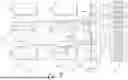
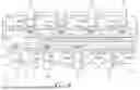


Sources:
- United States Patent and Trademark Office - verify current appl. status at the USPTO↗
Recent applications in this class:
- » 20260146521 2026-05-28
AUTOMATED BLEED-OFF SYSTEM FOR A FLUID SYSTEM - » 20260146520 2026-05-28
ENGINE LOAD MANAGEMENT IN A HYDRAULIC FRACTURING SYSTEM USING A SLIP DEVICE - » 20260146519 2026-05-28
TORQUE CONTROL WITH A SLIP DEVICE FOR PRESSURE TESTING A HYDRAULIC FRACTURING SYSTEM - » 20260146518 2026-05-28
PUMP MAINTENANCE FOR SPLIT FLOW WELLBORE SERVICES SYSTEM - » 20260139577 2026-05-21
HYBRID ELECTRIC TRANSMISSION FOR INERTIAL AND NON-INERTIAL LOADS - » 20260125975 2026-05-07
FLUID END - » 20260125974 2026-05-07
PASSIVE COOLING SYSTEM FOR A POST-COMBUSTION CARBON CAPTURE UNIT PROVIDING WATER MAKE-UP INTEGRATED WITH A SHALE OIL PRODUCTION AND NATURAL GAS COMPRESSOR STATION OPERATION - » 20260117636 2026-04-30
HYDRAULIC FRACTURING HOSE HANDLING ASSEMBLY AND METHODS OF USE - » 20260117635 2026-04-30
PIPING SYSTEMS AND METHODS WITH AN AUGER ASSEMBLY - » 20260103970 2026-04-16
ELECTRIC HYDRAULIC FRACTURING RIG SYSTEM AND METHOD