INTEGRATED RAPID EXCAVATION EQUIPMENT FOR ROCK ROADWAYS AND METHOD THEREOF
US20260146533A1
2026-05-28
19/401,493
2025-11-26
Smart Summary: The integrated rapid excavation equipment is designed to quickly break through rock roadways. It has a special drilling rig that creates deep holes in the rock before excavation begins. A pulse fracturing system is then used to weaken the rock further. After that, an oscillatory cutting part mills the rock into smaller pieces. Finally, the equipment provides support and bolting to stabilize the rock after excavation. 🚀 TL;DR
Abstract:
An integrated rapid excavation equipment for rock roadways and a method thereof are provided. The excavation equipment is provided with a multi-function drilling rig on one side of the boom-type roadheader body and a temporary support mechanism above an oscillatory cutting part. Before the excavation equipment breaks the rock, the multi-function drilling rig is used to form deep holes in the rock to be broken, the pulse fracturing system is then utilized to further expand and fracture the deep holes to weaken the rock mass strength, the oscillatory cutting part is subsequently employed to mill the rock mass, and finally, the multi-function drilling rig and the temporary support device are used for bolting and support on the rock mass.
Inventors:
- Dan MA 1 🇨🇳 Xuzhou City, China
- Qiang LI 1 🇨🇳 Xuzhou City, China
- Jinghong YAN 1 🇨🇳 Xuzhou City, China
- Hongxiang JIANG 1 🇨🇳 Xuzhou City, China
- Kuirun ZHANG 1 🇨🇳 Xuzhou City, China
- Quanhui LIU 1 🇨🇳 Xuzhou City, China
- Wentao HOU 1 🇨🇳 Xuzhou City, China
- Wenhao ZHANG 1 🇨🇳 Xuzhou City, China
Applicant:
Interested in similar patents?
Get notified when new applications in this technology area are published.
Classification:
E21D9/1013 » CPC main
Tunnels or galleries, with or without linings; Methods or apparatus for making thereof ; Layout of tunnels or galleries; Making by using boring or cutting machines with rotary cutting tools on a tool-carrier supported by a movable boom
E21D20/003 » CPC further
Setting anchoring-bolts Machines for drilling anchor holes and setting anchor bolts
E21D21/0053 » CPC further
Anchoring-bolts for roof, floor in galleries or longwall working , or shaft-lining protection characterised by constructional features of the bolts Anchoring-bolts in the form of lost drilling rods
E21D23/00 » CPC further
Mine roof supports for step- by- step movement, e.g. in combination with provisions for shifting of conveyors, mining machines, or guides therefor
E21D9/10 IPC
Tunnels or galleries, with or without linings; Methods or apparatus for making thereof ; Layout of tunnels or galleries Making by using boring or cutting machines
E21D20/00 IPC
Setting anchoring-bolts
E21D21/00 IPC
Anchoring-bolts for roof, floor in galleries or longwall working , or shaft-lining protection
Description
CROSS-REFERENCE TO RELATED APPLICATIONS
This application claims priority to Chinese Patent Application No. 202411721758.4, filed on Nov. 28, 2024, the contents of which are hereby incorporated by reference.
TECHNICAL FIELD
The present disclosure relates to the technical field of engineering machinery, and in particular to an integrated rapid excavation equipment for rock roadways and a method thereof.
BACKGROUND
Coal mining is predominantly conducted via underground mining, and roadway excavation serves as a critical prerequisite. The continuous improvements in coal mining technology and equipment have also led to higher demands for excavation operations. Currently, the total length of newly excavated roadways in China reaches 12,000 kilometers annually, over 80% of which are coal roadways. However, roadway excavation still relies on conventional processes such as drilling, charging, blasting, transportation, and construction. The average excavation speed of coal roadways is less than 200 meters per month, requiring a workforce exceeding 700,000. Slow excavation progress, high labor requirements, and low intelligentization levels lead to tense mining-excavation coordination, making low excavation efficiency a primary factor that restricts safe and efficient coal mining. The boom-type roadheader is the core equipment for roadway excavation, possessing the ability to adapt to various geological conditions, a high degree of mechanization, flexibility and mobility, and may be used in conjunction with multiple follow-up equipment. At present, a complete and efficient excavation system has not been formed at the roadway excavation face, and a series of problems such as imbalance between excavation, support, transportation, and auxiliary operations exist. These issues prevent the full utilization of the roadheader's cutting capability, and the equipment's intelligentization level is low, with weak inter-system correlation, making centralized control unachievable. Therefore, how to achieve mechanized and efficient fragmentation of ultra-hard rock masses in coal mines has become a key issue and challenge in the rapid excavation of hard rock roadways.
In recent years, innovative practices in advanced drilling technology and equipment have been carried out from three aspects: integrated excavation and exploration, rapid advanced exploration, and comprehensive detection technology based on directional drilling, providing references for roadway excavation operations. Traditional operations employing “boom-type roadheader+anchor drilling rig” will be phased out, and equipment models integrating excavation, support, and transportation are gradually emerging. Integrated excavation-exploration machines such as the EBZ160T, EBZ220T, and EBZ260T series, produced by representatives including the Taiyuan Research Institute of China Coal Technology and Engineering Group and the Shijiazhuang Coal Mining Machinery Co., Ltd. have been applied in large and medium-sized coal mines. The drilling rig is installed on the side of the machine body and performs drilling at different angles via a two-stage telescopic oil cylinder. Drilling is conducted before construction; the drilling rig extends from the side of the machine body to the specified position and retracts to its original position after drilling completion without affecting normal excavation. Under the premise of ensuring the normal operation of the roadheader, it may effectively perform drilling detection and support within a certain range of the comprehensive excavation face, roof, floor, and both sides when coordinated with temporary support equipment. Provided geological conditions permit, segmented synchronous support using different equipment is employed to achieve the purpose of improving excavation efficiency.
Pulse hydraulic fracturing is a rock mass fracturing method improved based on traditional hydraulic fracturing processes. It is widely used in oil and gas extraction, hard rock excavation in coal mines, underground engineering construction, and other fields. Traditional hydraulic fracturing methods involve injecting high-pressure fluid into boreholes and utilizing the compressive-but-not-tensile resistance characteristic of rock to form fractures, thereby reducing rock mass strength and facilitating subsequent mining. However, traditional hydraulic fracturing methods are plagued by issues such as high energy consumption, difficulty in control, and rock stress concentration. Particularly in high-hardness rock formations and complex geological conditions, sustained high pressure may lead to non-uniform failure of the rock mass, affecting the stability and safety of the excavation process. Consequently, pulse hydraulic fracturing technology has gradually become an important improvement solution. Using the pulse hydraulic fracturing method to directionally fracture the hard rock mass at the roadway excavation face into slab-shaped rock of a certain thickness, followed by oscillatory cutting using alloy roller cutters, may improve rock fragmentation efficiency. Therefore, integrated excavation equipment combining drilling exploration, support, and cutting enables centralized and visual control between roadways. Compared with traditional operations, it may reduce excavation time, and the comprehensive excavation line exhibits higher levels of mechanization, automation, and intelligentization, representing a potential approach for achieving efficient and rapid roadway excavation.
SUMMARY
The technical problem to be solved by the present disclosure is to overcome the above-mentioned technical defects and to provide an integrated rapid excavation equipment for rock roadways and a method thereof.
To solve the above technical problem, the technical scheme provided by the present disclosure is: an integrated rapid excavation equipment for rock roadways, the excavation equipment includes:
-
- a crawler-type main frame, serving as a support platform for the overall structure;
- an oscillatory cutting part, disposed on the crawler-type main frame, including an oscillatory cutting head and a telescopic portion, configured for cutting the rock stratum through the extension and retraction of the telescopic portion and the vibration of the oscillatory cutting head;
- a multi-function drilling rig, disposed on one side of the crawler-type main frame, configured for drilling holes in the rock stratum and installing anchor bolts;
- a pulse fracturing system, connected to the oscillatory cutting part and disposed behind the telescopic portion, for fracturing the rock stratum by generating hydraulic pulses to improve cutting efficiency;
- a temporary support mechanism, disposed in front of the crawler-type main frame, for providing temporary support in an excavation process;
- a loading mechanism, disposed below the oscillatory cutting part, including a shovel plate and a star wheel conveying device disposed on the shovel plate, configured for collecting and loading the cut coal and rock;
- a conveyor belt, disposed behind the loading mechanism and connected to the loading mechanism, and configured for conveying the coal and rock to the rear of the excavation equipment; and
- a rear support part, disposed at the rear of the crawler-type main frame, and configured for stabilizing the position of the excavation equipment during operation.
In an embodiment, the oscillatory cutting part is rotatably connected to the front end of the telescopic portion via a connecting member, telescopic cylinders are respectively rotatably disposed above and below the pulse fracturing system, and the output ends of the telescopic cylinders disposed above and below are respectively rotatably connected to hinge seats disposed above and below the oscillatory cutting part.
In an embodiment, the oscillatory cutting head includes an alloy roller cutter, a front end cover, a front housing, a front sleeve, a rear sleeve, and a rear housing;
-
- the alloy roller cutter is fixed to a front end of the front end cover by bolts, forming a main component for cutting operations;
- the rear sleeve is connected to a front end of the rear housing by bolts and extends into the interior of the rear housing;
- an eccentric block shaft is rotatably disposed inside the rear sleeve via two deep groove ball bearings, where an eccentric block shaft end cover is disposed in front of the front deep groove ball bearing, and a shaft sleeve is disposed in front of a rear one of the deep groove ball bearings for adapting to the eccentric block shaft;
- a bent-axis motor is further installed behind the rear one of the deep groove ball bearings via a motor sleeve and a bearing sleeve, and the output end of the bent-axis motor is connected to the eccentric block shaft, the front sleeve is installed to the front end of the rear sleeve by bolts, the front end cover is rotatably disposed at the front end of the front sleeve via a cylindrical roller bearing and a retaining ring is disposed on the inner side of the cylindrical roller bearing.
In an embodiment, the multi-function drilling rig includes a sliding platform, a traveling mechanism, a mechanical arm, a rotary platform, a drilling rig guide rail, and a drilling machine;
-
- the sliding platform is disposed on the crawler-type main frame;
- the traveling mechanism includes a traveling body slidably disposed on the sliding platform, a traveling gear is provided inside the traveling body via a traveling motor, and a transmission rack meshing with the traveling gear is provided on the sliding platform;
- a first rotary member and a second rotary member are rotatably disposed at the front end of the traveling body about a vertical axis, the rear end of the mechanical arm is rotatably connected to the first rotary member about a first horizontal axis, two pitch swing cylinders are rotatably disposed on the second rotary member about a second horizontal axis, output ends of the pitch swing cylinders are rotatably connected to the bottom of the mechanical arm, left-right swing cylinders are further rotatably disposed on two sides of the front end of the traveling body and the output ends of two sides of the left-right swing cylinders are respectively rotatably connected to two sides of the first rotary member, and a pump station is disposed on the traveling body and is hydraulically connected to the pitch swing cylinders and the left-right swing cylinders;
- a first rotary motor is disposed on the front end of the mechanical arm, the output shaft of the first rotary motor is provided with a rotary platform capable of rotating about a third horizontal axis, a second rotary motor is disposed on the rotary platform and the output shaft of the second rotary motor is connected to the bottom of the drilling rig guide rail, the drilling machine is slidably disposed on the drilling rig guide rail via an electric slider, and a self-drilling anchor rod body is installed on the front end of the drilling machine via a rotary grouting adapter.
In an embodiment, the self-drilling anchor rod body includes a hollow anchor rod body, a drill bit, a connecting sleeve, and a centralizer;
-
- the hollow anchor rod body is formed by connecting two section rod bodies via the connecting sleeve, the drill bit is disposed on the front end of the hollow anchor rod body, the rear end of the drill bit is a hollow disc-shaped structure with fine holes distributed circumferentially, the centralizer is disposed on the front section rod body of the hollow anchor rod body, a bearing plate is sleeved on the rear section rod body of the hollow anchor rod body for pressing against the rock wall and reinforcing bolts are provided on the bearing plate, and the rear section rod body of the hollow anchor rod body is connected to a grouting machine via a rotary grouting adapter and a grouting pipe.
In an embodiment, the pulse fracturing system includes a pulse fracturing housing, a piston is movably disposed inside the pulse fracturing housing and the piston divides the inner cavity of the pulse fracturing housing into an oil chamber and a water chamber, an oil injection port of the oil chamber is connected to the hydraulic system of the excavation equipment, the telescopic portion is capable of moving back and forth within the water chamber, a water inlet of the water chamber is connected to a low-pressure water pump via a water inlet passage and a hydraulic operated check valve is provided on the water inlet passage, and a water outlet of the water chamber is connected to the hollow anchor rod body via a water outlet passage.
In an embodiment, the temporary support mechanism includes a top guard plate and a front support frame, the bottom of the front support frame is rotatably connected to the pulse fracturing housing via two support seats, support cylinders are respectively rotatably disposed on two sides of the pulse fracturing housing, a lifting cylinder is rotatably disposed above the pulse fracturing housing, the output ends of the support cylinders and the lifting cylinder are all rotatably connected to the front support frame, the top guard plate is rotatably disposed above the front support frame, a folding cylinder is rotatably disposed at the bottom of the front end of the top guard plate and the output end of the folding cylinder is rotatably connected to a front portion of the front support frame.
In an embodiment, the star wheel conveying device includes two sets of drive motors disposed on the shovel plate, output ends of the two of drive motors are respectively provided with a left star wheel and a right star wheel, a channel is formed between the left star wheel and the right star wheel for conveying broken rock, and the conveyor belt is disposed at the channel.
In an embodiment, the rear support part is rotatably disposed at the rear of the crawler-type main frame via a rear support cylinder, and multiple stabilizing cones are provided on a bottom of the rear support part.
The present disclosure further provides a method of the excavation equipment as described above, including the following steps:
-
- step 1: performing drilling and pulse hydraulic fracturing
- when fracturing hard rock masses with a Protodyakonov strength coefficient f>15 in a roadway, first, adjusting a position of the excavation equipment to place the excavation equipment in a middle of the roadway; utilizing the traveling mechanism to slide the excavation equipment on the sliding platform to a suitable position; driving the two pitch swing cylinders by the pump station to extend and lift the mechanical arm; then controlling one of the left-right swing cylinders to retract and another of the left-right swing cylinders to extend by the pump station, and cooperating with the first rotary member and the second rotary member to swing the mechanical arm to a position to be drilled; then adjusting a position of the drilling machine by the first rotary motor and the second rotary motor; driving the drilling machine to slide on the drilling rig guide rail by the electric slider to enable the self-drilling anchor rod body to enter the rock mass and form a long straight deep hole in the rock mass to be fractured; adjusting the drilling machine to release the front section rod body, driving the drilling machine to retract, sleeving the centralizer onto a rear end of the hollow anchor rod body drilled into the deep hole, then sleeving the rear section rod body through the connecting sleeve, adjusting the drilling machine to connect to the section rod body, re-driving the drilling machine to continue drilling in the formed long straight deep hole; repeating the above operations until a deep hole length reaches 10 meters (m), driving the drilling machine to exit the long straight deep hole; removing lengthened section rod bodies; driving the mechanical arm and the drilling machine to move to a next position to be drilled; repeating the above operations until multiple long straight deep holes with a length of 10 m are drilled; and driving the mechanical arm to exit a working plane, driving the traveling mechanism to an initial position, and completing a drilling work; and
- subsequently, sealing the multiple long straight deep holes with high-pressure hole packers; injecting pulse water into the multiple long straight deep holes by the pulse fracturing system; further expanding and fracturing the long straight deep holes under an action of pulse hydraulic force; when an expansion range of fractures meets requirements is observed, completing the pulse hydraulic fracturing, and then removing the high-pressure hole packers;
- step 2: performing oscillatory cutting, loading and transportation
- adjusting the position of the excavation equipment to place the excavation equipment in the middle of the roadway; driving the telescopic cylinders to adjust the oscillatory cutting head to enable the alloy roller cutter to align with the expanded deep holes; driving the excavation equipment to move forward to enable the alloy roller cutter to enter the expanded deep holes; simultaneously adjusting the telescopic cylinders to enable the alloy roller cutter to fracture the rock mass according to a cutting path; then loading broken and fallen rock fragments through the loading mechanism; transporting the broken and fallen rock fragments through the conveyor belt; and continuously repeating the above process until a cutting depth reaches 1 m;
- step 3: performing temporary support and bolting support
- after completion of the process in step 2, adjusting the excavation equipment to place the excavation equipment in a suitable position; supplying hydraulic oil by a hydraulic pump station of the excavation equipment to push the hydraulic oil into the support cylinders, folding cylinder, and lifting cylinder of the temporary support mechanism; driving the lifting cylinder to lift the temporary support mechanism; then driving the folding cylinder to raise the front support frame, simultaneously driving the support cylinders to raise the top guard plate; and coordinating and operating the support cylinders, the folding cylinder, and the lifting cylinder through a multi-way directional control valve until the top guard plate and the front support frame are adjusted to a specified height and angle and reach a specified supporting force, then stopping;
- driving the traveling mechanism of the multi-function drilling rig to advance on the sliding platform to a suitable position; driving the mechanical arm to advance the drilling machine to a position to be bolted and supported; fixing the drilling machine onto the front section rod body of the hollow anchor rod body by the centralizer; adjusting an angle of the drilling machine, and connecting the rear section rod body of the hollow anchor rod body to the drilling machine via the rotary grouting adapter; and
- driving the drilling machine to advance the drill bit, simultaneously performing grouting by the grouting machine to achieve an effect of simultaneous drilling and grouting, until grout flows back from a hole mouth for 1 minute, then stopping the grouting; after the grout solidifies, installing the bearing plate on an exposed section of the hollow anchor rod body and enabling the bearing plate to abut against a rock surface; then fixing the bearing plate with the reinforcing bolt until the bearing plate is pressed tightly against the rock surface; repeating above operations until all positions to be bolted and supported are completed; when the grouting machine performs the grouting, pure cement grout or a 1:1 sand-cement grout is used, a particle size of sand in the grout is ≤1.0 millimeter (mm), and a water-cement ratio is controlled between 0.4-0.5; and
- Step 4: performing cyclical excavation and support operations until the roadway is penetrated through
- after completing above three steps, in other words, 1 m of roadway excavation is completed; repeating the two steps of the performing oscillatory cutting, loading and transporting as well as the performing temporary support and bolting support until the multiple 10 m deep holes in step 1 are milled complete, and completing one stage of roadway excavation; and repeating the three steps of the performing drilling and pulse hydraulic fracturing, the performing oscillatory cutting, loading and transporting, and the performing temporary support and bolting support until the roadway excavation is completed.
Compared with the prior art, the beneficial technical effects of adopting the above technical scheme in the present disclosure are as follows.
The present disclosure integrates drilling exploration, pulse fracturing, oscillatory cutting, and support operations into a single piece of equipment. The multi-function drilling rig may complete deep hole drilling exploration and grouting support on one side of the roadheader, reducing the connection time between processes. The temporary support device is located above the oscillatory cutting part and provides real-time support to the rock mass in the cutting area through the top guard plate and the front support frame, avoiding the risk of rock stratum collapse caused by delayed support in traditional roadway excavation. This disclosure improves the overall continuity of roadway excavation operations, reduces the frequency of equipment movement and time waste, and achieves full mechanization and automation of drilling exploration, cutting, and support operations, making it suitable for excavation scenarios requiring high safety and high efficiency in coal mines and other underground engineering projects.
The pulse hydraulic fracturing system performs directional fracturing of the rock mass inside the drill hole through pulse water flow, causing the rock mass to gradually form a fracture network under the impact of high-frequency water pressure. This process fully utilizes the compressive-but-not-tensile resistance characteristic of rock, effectively reduces the strength of the rock mass, and forms a bedding structure conducive to cutting. The periodic impact design of pulse fracturing not only effectively avoids the damage to rock stratum stability caused by sustained high pressure but also further expands the fractures, creating conditions for subsequent oscillatory cutting. Compared with traditional hydraulic fracturing methods, pulse hydraulic fracturing has the advantages of energy saving and strong controllability, wider adaptability, and may be applied to the excavation of ultra-hard rock roadways and complex geological conditions.
The oscillatory cutting head in this disclosure adopts a combination of an alloy roller cutter and an eccentric block shaft, enabling high-frequency oscillatory cutting, and allowing the cutting head to perform precise cutting on rock masses at different depths. This design utilizes the rotation of the eccentric block shaft to excite the eccentric oscillatory cutting of the roller cutter. This technology reduces resistance during hard rock cutting, making the fragmentation process more efficient and stable. This improvement reduces the load and wear on the equipment, prolongs the service life of the equipment, and significantly improves the efficiency of hard rock excavation, making it suitable for excavation operations in hard rock strata roadways.
BRIEF DESCRIPTION OF THE DRAWINGS
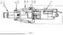
FIG. 1 is a schematic structural diagram of an integrated rapid excavation equipment for rock roadways according to the present disclosure.
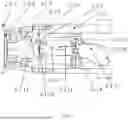
FIG. 2 is a schematic structural diagram of an oscillatory cutting part in the present disclosure.
FIG. 3 is a schematic internal structural diagram of an oscillatory cutting head in the present disclosure.
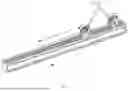
FIG. 4 is a structural diagram of a multi-function drilling rig in the present disclosure.
FIG. 5 is a schematic diagram of meshing transmission and advancement of a traveling gear and a rack in a traveling mechanism of the multi-function drilling rig in the present disclosure.
FIG. 6 is a schematic diagram of bolting support of the multi-function drilling rig in the present disclosure.
FIG. 7 is a schematic internal structural diagram of a pulse fracturing system in the present disclosure.
FIG. 8 is a structural diagram of a temporary support mechanism in the present disclosure.
FIG. 9 is a structural diagram of a loading mechanism in the present disclosure.
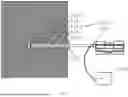
FIG. 10 is a schematic diagram of hole sealing and hydraulic fracturing of a high-pressure hole packer in the present disclosure.
FIG. 11 is a flowchart of a use method of the excavation equipment according to the present disclosure.
DETAILED DESCRIPTION OF THE EMBODIMENTS
In the following, the technical solutions in the embodiments of the present disclosure will be clearly and completely described with reference to the attached drawings. Apparently, the described embodiments are only a part of the embodiments of the present disclosure, but not all the embodiments. Based on the embodiments in the present disclosure, all other embodiments obtained by one of ordinary skill in the art without creative effort belong to the protection scope of the present disclosure.
It should be noted that all directional indications (such as up, down, left, right, front, rear . . . ) in the embodiments of the present disclosure are only used to explain the relative positional relationships, movement conditions, etc., between various components in a specific posture (as shown in the accompanying drawings). If the specific posture changes, the directional indication shall change accordingly.
In an embodiment, the descriptions involving “first”, “second”, etc., in the present disclosure are for descriptive purposes only and are not to be construed as indicating or implying their relative importance or implicitly specifying the quantity of the indicated technical features. Thus, features defined by “first”, “second” may explicitly or implicitly include at least one such feature. In the description of the present disclosure, “multiple” means at least two, such as two, three, etc., unless otherwise explicitly and specifically defined.
Moreover, the technical schemes of the various embodiments of the present disclosure may be combined with each other, but such combination must be achievable by a person of ordinary skill in the art. When the combination of technical solutions results in mutual contradiction or impossibility of implementation, it shall be considered that such combination of technical solutions does not exist and is not within the claimed protection scope of the present disclosure.
As shown in FIG. 1, an integrated rapid excavation equipment for rock roadways includes: a crawler-type main frame 1, serving as a support platform for the overall structure; an oscillatory cutting part 2, disposed on the crawler-type main frame 1, including an oscillatory cutting head 2-1 and a telescopic portion 2-4, and it is for cutting the rock stratum through the extension and retraction of the telescopic portion 2-4 and the vibration of the oscillatory cutting head 2-1; a multi-function drilling rig 3, disposed on one side of the crawler-type main frame 1, and it is for drilling holes in the rock stratum and installing anchor bolts; a pulse fracturing system 8, connected to the oscillatory cutting part 2 and disposed behind the telescopic portion 2-4, and it is for fracturing the rock stratum by generating hydraulic pulses to improve cutting efficiency; a temporary support mechanism 4, disposed in front of the crawler-type main frame 1, and it is for providing temporary support during the excavation process; a loading mechanism 5, disposed below the oscillatory cutting part 2, including a shovel plate 5-2 and a star wheel conveying device disposed on the shovel plate 5-2, and it is for collecting and loading the cut coal and rock; a conveyor belt 6, disposed behind the loading mechanism 5 and connected to the loading mechanism 5, and it is for conveying the coal and rock to the rear of the excavation equipment; and a rear support part 7, disposed at the rear of the crawler-type main frame 1, and it is for stabilizing the position of the excavation equipment during operation.
In an embodiment, as shown in FIG. 2, the oscillatory cutting part 2 is rotatably connected to the front end of the telescopic portion 2-4 via a connecting member. Telescopic cylinders 2-3 are respectively disposed above and below the pulse fracturing system 8, and these telescopic cylinders 2-3 are capable of rotating about their axes. The output ends of the telescopic cylinders 2-3 are rotatably connected to hinge seats 2-2 disposed above and below the oscillatory cutting part 2, respectively. By independently adjusting the extension or retraction state of these two telescopic cylinders 2-3, the present disclosure may precisely control the upward and downward swing angle of the oscillatory cutting head 2-1. Specifically, when the output end of the upper telescopic cylinder 2-3 extends and the output end of the lower telescopic cylinder 2-3 retracts, the oscillatory cutting head 2-1 swings downward accordingly; conversely, when the output end of the upper telescopic cylinder 2-3 retracts and the output end of the lower telescopic cylinder 2-3 extends, the oscillatory cutting head 2-1 swings upward. This enables the excavation equipment to adapt to rock masses of different hardness and angles, improving the flexibility and adaptability of the excavation operation.
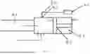
Specifically, as shown in FIG. 3, the oscillatory cutting head 2-1 includes an alloy roller cutter 2-1-1, a front end cover 2-1-2, a front housing 2-1-3, a front sleeve 2-1-5, a rear sleeve 2-1-6, and a rear housing 2-1-7; the alloy roller cutter 2-1-1 is fixed to the front end of the front end cover 2-1-2 by bolts, forming the main component for cutting operations; the rear sleeve 2-1-6 is connected to the front end of the rear housing 2-1-7 by bolts and extends into the interior of the rear housing 2-1-7; an eccentric block shaft 2-1-9 is rotatably disposed inside the rear sleeve 2-1-6 via two deep groove ball bearings 2-1-8, where an eccentric block shaft end cover 2-1-10 is further disposed in front of the front deep groove ball bearing 2-1-8, and a shaft sleeve 2-1-11 is disposed in front of the rear one of the deep groove ball bearings 2-1-8 for adapting to the eccentric block shaft 2-1-9; a bent-axis motor 2-1-13 is further installed behind the rear one of the deep groove ball bearings 2-1-8 via a motor sleeve 2-1-14 and a bearing sleeve 2-1-15, and the output end of the bent-axis motor 2-1-13 is connected to the eccentric block shaft 2-1-9, the front sleeve 2-1-5 is installed to the front end of the rear sleeve 2-1-6 by bolts, the front end cover 2-1-2 is rotatably disposed at the front end of the front sleeve 2-1-5 via a cylindrical roller bearing 2-1-4 and a retaining ring 2-1-12 is further disposed on the inner side of the cylindrical roller bearing 2-1-4, which may be used to share the cutting dynamic load. The eccentric block shaft 2-1-9 and the bent-axis motor 2-1-13 are connected by splines, and the axis of the eccentric block shaft 2-1-9 has an eccentric angle of 4-5 degrees (°). The oscillatory cutting head 2-1 in the present disclosure not only integrates core components such as the alloy roller cutter 2-1-1, front end cover 2-1-2, front housing 2-1-3, front sleeve 2-1-5, rear sleeve 2-1-6, and rear housing 2-1-7, but also incorporates multiple optimized features in its design. The alloy roller cutter 2-1-1, as the main force for cutting operations, is made of high-performance wear-resistant alloy material and is coated with a hard alloy layer on the surface to enhance its durability and cutting efficiency. Furthermore, the front end cover 2-1-2 and the front sleeve 2-1-5 achieve flexible rotation via the cylindrical roller bearing 2-1-4, and the addition of the retaining ring 2-1-12 not only ensures smooth rotation but also effectively shares the huge dynamic load generated during cutting, protecting the internal structure from damage. The eccentric block shaft 2-1-9 installed inside the rear sleeve 2-1-6 is designed with an eccentric angle of 4-5°, and, in cooperation with the spline connection of the bent-axis motor 2-1-13, may generate periodic oscillatory excitation when driven by the bent-axis motor 2-1-13. This design not only improves cutting efficiency but also effectively reduces cutting resistance and energy consumption. Both ends of the eccentric block shaft 2-1-9 are supported by the two deep groove ball bearings 2-1-8, respectively; the front end is fixed by the eccentric block shaft end cover 2-1-10, and the rear end is adapted and connected to the output end of the bent-axis motor 2-1-13 via the shaft sleeve 2-1-11, ensuring the stability and reliability of the transmission. The entire oscillatory cutting head 2-1 has a compact structure and precise coordination between components, ensuring efficient cutting operations while being easy to maintain and service, making it an indispensable high-efficiency tool in engineering fields such as mining and tunneling.
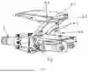
In a specific and detailed embodiment, as shown in FIG. 4 and FIG. 5, the multi-function drilling rig 3 is a highly integrated and flexible drilling device, which mainly consists of the following key components: a sliding platform 3-1, a traveling mechanism 3-2, a mechanical arm 3-5, a rotary platform 3-6, a drilling rig guide rail 3-7, and a drilling machine 3-8. These components work together to enable the multi-function drilling rig 3 to perform efficient and precise drilling tasks in various complex environments. The sliding platform 3-1 is the mobile base of the entire device and is connected to the crawler-type main frame 1.
The traveling mechanism 3-2 includes a traveling body 3-12 slidably disposed on the sliding platform 3-1. A traveling gear 3-17 is driven to rotate by a traveling motor inside the traveling body 3-12. A transmission rack meshing with the traveling gear 3-17 is provided on the sliding platform 3-1, so that the traveling gear 3-17 may drive the traveling body 3-12 to move on the sliding platform 3-1 via the transmission rack, thereby realizing the overall movement of the traveling body 3-12.
A first rotary member 3-3 and a second rotary member 3-4 are rotatably disposed at the front end of the traveling body 3-12 about a vertical axis, the rear end of the mechanical arm 3-5 is rotatably connected to the first rotary member 3-3 about a horizontal axis, a pitch swing cylinder 3-10 is rotatably disposed on the second rotary member 3-4 about a horizontal axis and the output end of the pitch swing cylinder 3-10 is rotatably connected to the bottom of the mechanical arm 3-5, left-right swing cylinders 3-9 are further rotatably disposed on both sides of the front end of the traveling body 3-12 and the output ends of the left-right swing cylinders 3-9 on both sides are rotatably connected to both sides of the first rotary member 3-3, respectively. A pump station 3-14 hydraulically connected to the pitch swing cylinder 3-10 and the left-right swing cylinders 3-9 is further disposed on the traveling body 3-12; a first rotary motor 3-18 is disposed at the front end of the mechanical arm 3-5, the output shaft of the first rotary motor 3-18 is provided with a rotary platform 3-6 capable of rotating about a horizontal axis, a second rotary motor 3-15 is disposed on the rotary platform 3-6 and the output shaft of the second rotary motor 3-15 is connected to the bottom of the drilling rig guide rail 3-7, the drilling machine 3-8 is slidably disposed on the drilling rig guide rail 3-7 via an electric slider, and a self-drilling anchor rod body 3-13 is installed at the front end of the drilling machine 3-8 via a rotary grouting adapter 3-11. At the front end of the traveling body 3-12, the first rotary member 3-3 and the second rotary member 3-4 are rotatably disposed about a vertical axis, providing flexible rotation space for the mechanical arm 3-5. The rear end of the mechanical arm 3-5 is rotatably connected to the first rotary member 3-3 about a horizontal axis, enabling it to rotate in the horizontal plane. To further enhance the flexibility of the mechanical arm 3-5, the pitch swing cylinder 3-10 is rotatably disposed on the second rotary member 3-4 about a horizontal axis, and its output end is rotatably connected to the bottom of the mechanical arm 3-5. By adjusting the extension and retraction of the pitch swing cylinder 3-10, the pitch swing of the mechanical arm 3-5 in the vertical plane may be achieved. Furthermore, the left-right swing cylinders 3-9 are rotatably disposed on both sides of the front end of the traveling body 3-12. The output ends of these two left-right swing cylinders 3-9 are rotatably connected to the two sides of the first rotary member 3-3, respectively. By simultaneously adjusting the extension and retraction of the two left-right swing cylinders 3-9, the left-right swing of the mechanical arm 3-5 in the horizontal plane may be achieved, thereby further expanding the working range of the mechanical arm 3-5.
To ensure the stable operation of the pitch swing cylinder 3-10 and the left-right swing cylinders 3-9, the pump station 3-14 is disposed on the traveling body 3-12 and is hydraulically connected to them. The pump station 3-14 provides a stable and reliable hydraulic power source for these cylinders, ensuring that the mechanical arm 3-5 may flexibly and accurately complete various movements.
In a specific embodiment disclosed in the present disclosure, as shown in FIG. 6, the self-drilling anchor rod body 3-13 includes a hollow anchor rod body 3-13-1, a drill bit 3-13-2, a connecting sleeve 3-13-3, and a centralizer 3-13-4; the hollow anchor rod body 3-13-1 is formed by connecting two section rod bodies via the connecting sleeve 3-13-3, the drill bit 3-13-2 is disposed at the front end of the hollow anchor rod body 3-13-1, the rear end of the drill bit 3-13-2 is a hollow disc-shaped structure with fine holes distributed circumferentially, the centralizer 3-13-4 is disposed on the front section rod body of the hollow anchor rod body 3-13-1, a bearing plate 3-13-5 is sleeved on the rear section rod body of the hollow anchor rod body 3-13-1 for pressing against the rock wall and a reinforcing bolt 3-13-6 is provided on the bearing plate 3-13-5, and the rear section rod body of the hollow anchor rod body 3-13-1 is further connected to a grouting machine 3-16 via the rotary grouting adapter 3-11 and a grouting pipe. The reinforcing bolt 3-13-6 and the bearing plate 3-13-5 are used in cooperation; the reinforcing bolt 3-13-6 first transfers the anchoring force of the hollow anchor rod body 3-13-1 to the bearing plate 3-13-5, and the bearing plate 3-13-5 then applies the anchoring force to the surrounding rock, transferring stress, improving the end force condition, and enhancing the anchoring effect of the self-drilling bolt. The centralizer 3-13-4 ensures that the self-drilling anchor rod body is always located at the center of the drill hole during the construction process, thereby ensuring a uniform thickness of grout around the anchor rod body and further strengthening the anchoring effect.
In a specific embodiment disclosed in the present disclosure, as shown in FIG. 7, the pulse fracturing system 8 includes a pulse fracturing housing 8-1, a piston 8-2 is movably disposed inside the pulse fracturing housing 8-1 and the piston 8-2 divides the inner cavity of the pulse fracturing housing 8-1 into an oil chamber 8-3 and a water chamber 8-4, an oil injection port of the oil chamber 8-3 is connected to the hydraulic system of the excavation equipment, the telescopic portion 2-4 is capable of moving back and forth within the water chamber 8-4, a water inlet of the water chamber 8-4 is connected to a low-pressure water pump 8-5 via a water inlet passage and a hydraulic operated check valve 8-6 is provided on the water inlet passage, and a water outlet of the water chamber 8-4 is further connected to the hollow anchor rod body 3-13-1 via a water outlet passage. This system uses the movement of the piston 8-2 to generate pressure changes in water and oil, thereby generating hydraulic pulses. Specifically, the oil chamber 8-3 is pressurized by injecting oil through the hydraulic system of the excavation equipment, forming a high-pressure oil flow that pushes the piston 8-2 in the oil chamber 8-3 towards the water chamber 8-4. The low-pressure water pump 8-5 supplies water pressure to the water chamber 8-4 inside the equipment through the hydraulic operated check valve 8-6 and the water inlet. The oil chamber 8-3 and the water chamber 8-4 are separated by the piston 8-2. As the piston 8-2 moves, the water in the water chamber 8-4 flows to the water outlet connected to the hollow anchor rod body 3-13-1 under a certain pressure, while the oscillatory cutting head 2-1 and the telescopic portion 2-4 extend and retract driven by the telescopic cylinders 2-3 under the action of the water pressure in the water chamber 8-4 to share the water pressure. When the pulse pressure reaches a certain value, the hydraulic operated check valve 8-6 controls the flow direction of the liquid, causing water to eject from the water outlet and, and further act on the fracture zone through the high-pressure hole packer 9. After the water flows into the drill hole, the pulse water transmitted by the pulse fracturing system acts on the rock stratum, forming an impact force, thereby generating cracks in the rock. By periodically pulsing water, an expanding fracture network may be initiated within the rock stratum, achieving hydraulic fracturing of the rock stratum. This process is cyclically repeated, enabling the equipment to continuously generate pulse water flow, thereby continuously impacting the rock stratum at high frequency.
In a specific embodiment disclosed in the present disclosure, as shown in FIG. 8, the temporary support mechanism 4 includes a top guard plate 4-1 and a front support frame 4-2, the bottom of the front support frame 4-2 is rotatably connected to the pulse fracturing housing 8-1 via two support seats 4-5, support cylinders 4-3 are rotatably disposed on both sides of the pulse fracturing housing 8-1 and a lifting cylinder 4-6 is further rotatably disposed above the pulse fracturing housing 8-1, the output ends of the support cylinders 4-3 and the lifting cylinder 4-6 are all rotatably connected to the front support frame 4-2, the top guard plate 4-1 is rotatably disposed above the front support frame 4-2, folding cylinders 4-4 are further rotatably disposed at the bottom of the front end of the top guard plate 4-1 and the output end of each folding cylinder 4-4 is rotatably connected to the front part of the front support frame 4-2. The temporary support mechanism 4 is powered by the hydraulic system of the excavation equipment, and is driven by hydraulic oil. During operation, the support cylinders 4-3 and the lifting cylinder 4-6 extend to lift the front support frame 4-2 to a certain height and then stop moving. The folding cylinder 4-4 extends to prop up the top guard plate 4-1 tightly against the upper rock wall. When retracting, the folding cylinder 4-4 first retracts to fold down the top guard plate 4-1, and then the support cylinders 4-3 and the lifting cylinder 4-6 retract to fold down the front support frame 4-2. The entire temporary support mechanism 4 has strong adaptability to the excavation equipment body and high flexibility of its own actuating mechanisms.
In a specific embodiment disclosed in the present disclosure, as shown in FIG. 9, the star wheel conveying device includes two of drive motors 5-3 disposed on the shovel plate 5-2, the output ends of the two of drive motors 5-3 are respectively provided with a left star wheel 5-1 and a right star wheel 5-4, a channel is formed between the left star wheel 5-1 and the right star wheel 5-4 for conveying broken rock, and the conveyor belt 6 is disposed at the channel. The function of the star wheel conveying device is to collect and load the broken coal and rock onto the conveyor belt 6 and transport them to the rear of the crawler belt. Specifically, the shovel plate 5-2 scoops up the broken rock, and the drive motors 5-3 drive the left star wheel 5-1 and the right star wheel 5-4 to rotate in opposite directions, so as to continuously transport the scooped broken rock to the conveyor belt 6.
In a specific embodiment, the rear support part 7 is rotatably disposed at the rear of the crawler-type main frame 1 via a rear support cylinder, and multiple stabilizing cones are provided at the bottom of the rear support part 7. The rear support part 7 and the rear support cylinder are both rotatably disposed at the rear of the crawler-type main frame 1, and the output end of the rear support cylinder is rotatably connected to the rear support part 7, so that under the action of the extension and retraction of the support cylinder, the rear support part 7 may rotate to the ground to achieve stable support.
As shown in FIG. 11, the present disclosure further provides a use method of the integrated rapid excavation equipment for rock roadways, including the following steps:
-
- Step 1: performing drilling and pulse hydraulic fracturing
- when fracturing hard rock masses with a Protodyakonov strength coefficient f>15 in a roadway, first, adjusting a position of the excavation equipment to place the excavation equipment in a middle of the roadway; utilizing the traveling mechanism 3-2 to slide the excavation equipment on the sliding platform 3-1 to a suitable position; driving the two pitch swing cylinders 3-10 by the pump station 3-14 to extend and lift the mechanical arm 3-5; then controlling one left-right swing cylinder 3-9 to retract and the other left-right swing cylinder 3-9 to extend by the pump station 3-14, and cooperating with the first rotary member 3-3 and the second rotary member 3-4 to swing the mechanical arm 3-5 to a position to be drilled; then adjusting a position of the drilling machine 3-8 by utilizing the first rotary motor 3-18 and the second rotary motor 3-15; driving the drilling machine 3-8 to slide on the drilling rig guide rail 3-7 by the electric slider to make the self-drilling anchor rod body 3-13 enter the rock mass and form a long straight deep hole in the rock mass to be fractured; adjusting the drilling machine 3-8 to release the front hollow section rod body at the front end, driving the drilling machine 3-8 to retract, sleeving the centralizer 3-13-4 onto the rear end of the hollow anchor rod body 3-13-1 already drilled into the deep hole, then using the connecting sleeve 3-13-3 to sleeve another hollow section rod body, adjusting the drilling machine 3-8 to connect to the section rod body, re-driving the drilling machine 3-8 to continue drilling in the already formed long straight deep hole; repeating the above operations until the deep hole length reaches 10 meters (m), driving the drilling machine 3-8 to exit the deep hole; removing lengthened section rod bodies; driving the mechanical arm 3-5 and the drilling machine 3-8 to move to a next position to be drilled; repeating the above operations until multiple long straight deep holes with a length of 10 m are drilled. Finally, driving the mechanical arm 3-5 to exit a working plane, and driving the traveling mechanism 3-2 to an initial position, thereby completing the drilling work; and
- subsequently, sealing the long straight deep holes with high-pressure hole packers 9; injecting pulse water into the long straight deep holes by utilizing the pulse fracturing system 8; further expanding and fracturing the long straight deep holes under an action of pulse hydraulic force; when an expansion range of fractures meets requirements is observed, completing the pulse hydraulic fracturing work, and then removing the high-pressure hole packers 9 (as shown in FIG. 10);
- Step 2: performing oscillatory cutting and loading and transporting
- adjusting the position of the excavation equipment to place the excavation equipment in the middle of the roadway; driving the telescopic cylinders 2-3 to adjust the oscillatory cutting head 2-1 to make the alloy roller cutter 2-1-1 align with the expanded deep holes; driving the roadheader (i.e., the excavation equipment) to move forward to make the alloy roller cutter 2-1-1 enter the expanded deep holes; simultaneously adjusting the telescopic cylinders 2-3 to make the alloy roller cutter 2-1-1 fracture the rock mass according to a cutting path; then loading the broken and fallen rock fragments through the loading mechanism 5; transporting the broken and fallen rock fragments through the conveyor belt 6; and continuously repeating the above process until a cutting depth reaches 1 m;
- Step 3: performing temporary support and bolting support
- after completion of the process in Step 2, adjusting the excavation equipment to place the excavation equipment in a suitable position; supplying oil by utilizing a hydraulic pump station of the excavation equipment to push hydraulic oil into the support cylinders 4-3, folding cylinder 4-4, and lifting cylinder 4-6 of the temporary support mechanism 4; driving the lifting cylinder 4-6 to lift the entire temporary support mechanism 4; then driving the folding cylinder 4-4 to raise the front support frame 4-2, simultaneously driving the support cylinders 4-3 to raise the top guard plate 4-1; and coordinating operation of the support cylinders 4-3, the folding cylinder 4-4, and the lifting cylinder 4-6 through a multi-way directional control valve until the top guard plate 4-1 and the front support frame 4-2 are adjusted to a required height and angle and reach a required supporting force, then stopping the support cylinders, the folding cylinder, and the lifting cylinder ;
driving the traveling mechanism 3-2 of the multi-function drilling rig 3 to advance on the sliding platform 3-1 to a suitable position; driving the mechanical arm 3-5 to advance the drilling machine 3-8 to a position to be bolted and supported; fixing the drilling machine 3-8 onto a front section rod body of the hollow anchor rod body 3-13-1 by the centralizer 3-13-4; adjusting an angle of the drilling machine 3-8, and connecting the rear section rod body of the hollow anchor rod body 3-13-1 to the drilling machine 3-8 via the rotary grouting adapter 3-11; and
-
- driving the drilling machine 3-8 to advance the drill bit 3-13-2, simultaneously performing grouting by the grouting machine 3-16 to achieve an effect of simultaneous drilling and grouting, until grout flows back from a hole mouth for 1 minute, then stopping grouting; after the grout solidifies, installing the bearing plate 3-13-5 on an exposed section of the hollow anchor rod body 3-13-1 and enabling the bearing plate 3-13-5 to abut against the rock surface; then fixing the bearing plate 3-13-5 with the reinforcing bolt 3-13-6 until the bearing plate 3-13-5 presses tightly against the rock surface; repeating above operations until all positions to be bolted and supported are completed; when the grouting machine 3-16 performs grouting, pure cement grout or a 1:1 sand-cement grout is used, a particle size of sand in the grout is ≤1.0 millimeter (mm), and a water-cement ratio is controlled between 0.4-0.5; and
- Step 4: performing cyclical excavation and support operations until the roadway is penetrated through
- after completing above three steps, in other words, 1 m of roadway excavation is completed; repeating the steps of the performing oscillatory cutting, loading and transporting as well as the performing temporary support and bolting support, until the multiple 10 m deep holes in Step 1 are milled complete, thereby completing one stage of roadway excavation; and repeating the steps of performing the drilling and pulse hydraulic fracturing, the performing oscillatory cutting, loading and transporting, and the performing temporary support and bolting support, until the roadway excavation is completed. The present disclosure and its embodiments have been described above. The above-mentioned embodiment only describes the preferred mode of the present disclosure, does not limit the scope of the present disclosure, and the embodiment shown in the drawings are only one of the embodiments of the present disclosure. Under the premise of not departing from the design spirit of the present disclosure, various modifications and improvements made by one of ordinary skill in the art to the technical solution of the present disclosure should fall within the protection scope of the present disclosure.
Claims
What is claimed is:1. An integrated rapid excavation equipment for rock roadways, the excavation equipment comprising:
a crawler-type main frame, serving as a support platform for an overall structure;
an oscillatory cutting part, disposed on the crawler-type main frame, comprising an oscillatory cutting head and a telescopic portion, and configured for cutting a rock stratum through extension and retraction of the telescopic portion and vibration of the oscillatory cutting head;
a multi-function drilling rig, disposed on one side of the crawler-type main frame, and configured for drilling holes in the rock stratum and installing anchor bolts;
a pulse fracturing system, connected to the oscillatory cutting part and disposed behind the telescopic portion, and configured for fracturing the rock stratum by generating hydraulic pulses to improve cutting efficiency;
a temporary support mechanism, disposed in front of the crawler-type main frame, and configured for providing temporary support in an excavation process;
a loading mechanism, disposed below the oscillatory cutting part, comprising a shovel plate and a star wheel conveying device disposed on the shovel plate, and configured for collecting and loading cut coal and rock;
a conveyor belt, disposed behind the loading mechanism and connected to the loading mechanism, and configured for conveying the coal and rock to a rear of the excavation equipment; and
a rear support part, disposed at a rear of the crawler-type main frame, and configured for stabilizing a position of the excavation equipment during operation;
wherein the oscillatory cutting part is rotatably connected to a front end of the telescopic portion via a connecting member, telescopic cylinders are respectively rotatably disposed above and below the pulse fracturing system, and output ends of the telescopic cylinders disposed above and below are respectively rotatably connected to hinge seats disposed above and below the oscillatory cutting part;
the oscillatory cutting head comprises an alloy roller cutter, a front end cover, a front housing, a front sleeve, a rear sleeve, and a rear housing;
the alloy roller cutter is fixed to a front end of the front end cover by bolts, forming a main component for cutting operations;
the rear sleeve is connected to a front end of the rear housing by bolts and extends into an interior of the rear housing;
an eccentric block shaft is rotatably disposed inside the rear sleeve via two deep groove ball bearings, an eccentric block shaft end cover is disposed in front of a front one of the deep groove ball bearings, and a shaft sleeve is disposed in front of a rear one of the deep groove ball bearings for adapting to the eccentric block shaft; and
a bent-axis motor is installed behind the rear one of the deep groove ball bearings via a motor sleeve and a bearing sleeve, an output end of the bent-axis motor is connected to the eccentric block shaft, the front sleeve is installed to a front end of the rear sleeve by bolts, the front end cover is rotatably disposed at a front end of the front sleeve via a cylindrical roller bearing, and a retaining ring is disposed on an inner side of the cylindrical roller bearing;
wherein the multi-function drilling rig comprises a sliding platform, a traveling mechanism, a mechanical arm, a rotary platform, a drilling rig guide rail, and a drilling machine;
the sliding platform is disposed on the sliding platform;
the traveling mechanism comprises a traveling body slidably disposed on the sliding platform, a traveling gear is provided inside the traveling body via a traveling motor, and a transmission rack meshing with the traveling gear is provided on the sliding platform; and
a first rotary member and a second rotary member are rotatably disposed at a front end of the traveling body about a vertical axis, a rear end of the mechanical arm is rotatably connected to the first rotary member about a horizontal axis, pitch swing cylinders are rotatably disposed on the second rotary member about another horizontal axis, output ends of the pitch swing cylinders are rotatably connected to a bottom of the mechanical arm, left-right swing cylinders are rotatably disposed on two sides of the front end of the traveling body and output ends of two sides of the left-right swing cylinders are respectively rotatably connected to two sides of the first rotary member, and a pump station is disposed on the traveling body and is hydraulically connected to the pitch swing cylinders and the left-right swing cylinders;
a first rotary motor is disposed on a front end of the mechanical arm, the rotary platform is disposed on an output shaft of the first rotary motor and is capable of rotating about yet another horizontal axis, a second rotary motor is disposed on the rotary platform and an output shaft of the second rotary motor is connected to a bottom of the drilling rig guide rail, the drilling machine is slidably disposed on the drilling rig guide rail via an electric slider, and a self-drilling anchor rod body is installed on a front end of the drilling machine via a rotary grouting adapter;
wherein the self-drilling anchor rod body comprises a hollow anchor rod body, a drill bit, a connecting sleeve, and a centralizer;
the hollow anchor rod body is formed by connecting two section rod bodies via the connecting sleeve, the drill bit is disposed on a front end of the hollow anchor rod body, a rear end of the drill bit is a hollow disc-shaped structure with fine holes distributed circumferentially, the centralizer is disposed on a front section rod body of the hollow anchor rod body, a bearing plate is sleeved on a rear section rod body of the hollow anchor rod body for pressing against a rock wall and reinforcing bolts are provided on the bearing plate, and the rear section rod body of the hollow anchor rod body is connected to a grouting machine via the rotary grouting adapter and a grouting pipe; and
wherein the pulse fracturing system comprises a pulse fracturing housing, a piston is movably disposed inside the pulse fracturing housing and the piston divides an inner cavity of the pulse fracturing housing into an oil chamber and a water chamber, an oil injection port of the oil chamber is connected to a hydraulic system of the excavation equipment, the telescopic portion is capable of moving back and forth within the water chamber, a water inlet of the water chamber is connected to a low-pressure water pump via a water inlet passage, a hydraulic operated check valve is provided on the water inlet passage, and a water outlet of the water chamber is connected to the hollow anchor rod body via a water outlet passage.
2. The integrated rapid excavation equipment for rock roadways according to claim 1, wherein the temporary support mechanism comprises a top guard plate and a front support frame, a bottom of the front support frame is rotatably connected to the pulse fracturing housing via two support seats, support cylinders are respectively rotatably disposed on two sides of the pulse fracturing housing, a lifting cylinder is rotatably disposed above the pulse fracturing housing, output ends of the support cylinders and the lifting cylinder are all rotatably connected to the front support frame, the top guard plate is rotatably disposed above the front support frame, a folding cylinder is rotatably disposed at a bottom of a front end of the top guard plate, and an output end of the folding cylinder is rotatably connected to a front portion of the front support frame.
3. The integrated rapid excavation equipment for rock roadways according to claim 2, wherein the star wheel conveying device comprises two drive motors disposed on the shovel plate, output ends of the two drive motors are respectively provided with a left star wheel and a right star wheel, a channel is formed between the left star wheel and the right star wheel for conveying broken rock, and the conveyor belt is disposed at the channel.
4. The integrated rapid excavation equipment for rock roadways according to claim 3, wherein the rear support part is rotatably disposed at the rear of the crawler-type main frame via a rear support cylinder, and a plurality of stabilizing cones are provided on a bottom of the rear support part.
5. A method of using the integrated rapid excavation equipment for rock roadways according to claim 4, comprising following steps:
step 1: performing drilling and pulse hydraulic fracturing
when fracturing hard rock mass with a Protodyakonov strength coefficient f>15 in a roadway, first, adjusting a position of the excavation equipment to place the excavation equipment in a middle of the roadway, utilizing the traveling mechanism to slide the excavation equipment on the sliding platform to a first position, driving two pitch swing cylinders by the pump station to extend the pitch swing cylinders and lift the mechanical arm; then controlling one of the left-right swing cylinders to retract and another of the left-right swing cylinders to extend by the pump station, and cooperating with the first rotary member and the second rotary member to swing the mechanical arm to a position to be drilled, then adjusting a position of the drilling machine by the first rotary motor and the second rotary motor, driving the drilling machine to slide on the drilling rig guide rail by the electric slider to enable the self-drilling anchor rod body to enter the rock mass and form a long straight deep hole in the rock mass to be fractured, adjusting the drilling machine to release the front section rod body, driving the drilling machine to retract, sleeving the centralizer onto a rear end of the hollow anchor rod body drilled into the deep hole; then sleeving the rear section rod body through the connecting sleeve, adjusting the drilling machine to connect to the section rod bodies, re-driving the drilling machine to continue drilling in the formed long straight deep hole, repeating above operations until a deep hole length reaches 10 meters (m); driving the drilling machine to exit the long straight deep hole, removing lengthened section rod bodies, driving the mechanical arm and the drilling machine to move to a next position to be drilled, repeating above operations until a plurality of long straight deep holes with a length of 10 m are drilled; and driving the mechanical arm to exit a working plane, driving the traveling mechanism to an initial position, and completing a drilling work; and
subsequently, sealing the plurality of long straight deep holes with high-pressure hole packers, injecting pulse water into the plurality of long straight deep holes by the pulse fracturing system, further expanding and fracturing the long straight deep holes under an action of pulse hydraulic force, when an expansion range of fractures meets requirements is observed, completing the pulse hydraulic fracturing, and removing the high-pressure hole packers;
step 2: performing oscillatory cutting, loading and transporting
adjusting the position of the excavation equipment to place the excavation equipment in the middle of the roadway, driving the telescopic cylinders to adjust the oscillatory cutting head to enable the alloy roller cutter to align with the expanded long straight deep holes, driving a roadheader to move forward to enable the alloy roller cutter to enter the expanded long straight deep holes, simultaneously adjusting the telescopic cylinders to enable the alloy roller cutter to fracture the rock mass according to a cutting path, then loading broken and fallen rock fragments through the loading mechanism, transporting the broken and fallen rock fragments through the conveyor belt, and continuously repeating above process until a cutting depth reaches 1 m;
step 3: performing temporary support and bolting support
adjusting the excavation equipment to place the excavation equipment in a second position, supplying hydraulic oil by a hydraulic pump station of the excavation equipment to push the hydraulic oil into the support cylinders, folding cylinder, and lifting cylinder of the temporary support mechanism, driving the lifting cylinder to lift the temporary support mechanism; then driving the folding cylinder to raise the front support frame, simultaneously driving the support cylinders to raise the top guard plate, and coordinating and operating the support cylinders, the folding cylinder, and the lifting cylinder through a multi-way directional control valve until the top guard plate and the front support frame are adjusted to a specified height and angle and reach a specified supporting force, and then stopping;
driving the traveling mechanism of the multi-function drilling rig to advance on the sliding platform to a third position, driving the mechanical arm to advance the drilling machine to a position to be bolted and supported, fixing the drilling machine onto the front section rod body of the hollow anchor rod body by the centralizer, adjusting an angle of the drilling machine, and connecting the rear section rod body of the hollow anchor rod body to the drilling machine via the rotary grouting adapter; and
driving the drilling machine to advance the drill bit, simultaneously performing grouting by the grouting machine to achieve an effect of simultaneous drilling and grouting, until grout flows back from a hole mouth for 1 minute, then stopping the grouting; after the grout solidifies, installing the bearing plate on an exposed section of the hollow anchor rod body and enabling the bearing plate to abut against a rock surface; then fixing the bearing plate with the reinforcing bolts until the bearing plate is pressed tightly against the rock surface, repeating above operations until all positions to be bolted and supported are completed, wherein when the grouting machine performs the grouting, pure cement grout or a 1:1 sand-cement grout is used, a particle size of sand in the grout is ≤1.0 millimeter (mm), and a water-cement ratio is controlled between 0.4-0.5; and
step 4: performing cyclical excavation and support operations until the roadway is penetrated through
after completing above three steps, 1 m of roadway excavation is completed, repeating the two steps of the performing oscillatory cutting, loading and transporting, and the performing temporary support and bolting support until the plurality of long straight deep holes with the length of 10 m in the step 1 are milled complete, and completing one stage of the roadway excavation; and
repeating the three steps of the performing drilling and pulse hydraulic fracturing, the performing oscillatory cutting, loading and transporting, and the performing temporary support and bolting support until the roadway excavation is completed.
Images & Drawings included:


Sources:
- United States Patent and Trademark Office - verify current appl. status at the USPTO↗
Recent applications in this class:
- » 20220341323 2022-10-27
A MINING MACHINE AND A METHOD FOR ROCK EXCAVATION - » 20180223662 2018-08-09
Cutting apparatus using a clearing arrangement - » 20170306758 2017-10-26
Cutting apparatus and method of operating - » 20170268336 2017-09-21
Excavation assembly for use in excavator - » 20120313422 2012-12-13
Method and device for working rock