TUNNEL LINING ELEMENT
US20260146534A1
2026-05-28
18/871,771
2023-06-06
Smart Summary: A tunnel lining element is made up of at least two segments that fit together to form a closed structure. Each segment has two short sides where they connect with each other. On one side of each segment, there are special parts called connecting elements that help hold the segments together. These connecting elements have main bodies and flanges that create a strong grip between them. This design ensures that the tunnel lining is secure and stable. 🚀 TL;DR
Abstract:
The invention relates to a tunnel lining element (10) comprising at least two tunnel lining segments (11), with a body (20), the tunnel lining segment (11) comprising two opposing short sides (17) at which the at least two tunnel lining segments (11) are interconnected such that the tunnel lining element (10) is a closed element. According to the invention: at least a first connecting element (13) is located on the first short side of the tunnel lining segment (11), and at least a second connecting element (14) is located on the first short side of the tunnel lining segment (11); the connecting elements (13, 14) of two tunnel lining segments (11) form a connection (15) in a connecting region (12); the connecting elements (13, 14) each have at least one main body (30, 40); at least one flange portion (33, 43) is provided on each main body (30, 40); and a frictional connection (15) between the connecting elements (13, 14) is provided via the at least one flange portion (33) of the first connecting element (13) via the at least one flange portion (43) of the second connecting element (13).
Applicant:
Interested in similar patents?
Get notified when new applications in this technology area are published.
Classification:
E21D11/083 » CPC main
Lining tunnels, galleries or other underground cavities, e.g. large underground chambers; Linings therefor; Making such linings , e.g. by assembling; Lining with building materials with preformed concrete slabs Methods or devices for joining adjacent concrete segments
E21D9/005 » CPC further
Tunnels or galleries, with or without linings; Methods or apparatus for making thereof ; Layout of tunnels or galleries by forcing prefabricated elements through the ground, e.g. by pushing lining from an access pit
E21D11/08 IPC
Lining tunnels, galleries or other underground cavities, e.g. large underground chambers; Linings therefor; Making such linings , e.g. by assembling; Lining with building materials with preformed concrete slabs
E21D9/00 IPC
Tunnels; Galleries; Large underground chambers; Linings therefor
E21D9/00 IPC
Tunnels or galleries, with or without linings; Methods or apparatus for making thereof ; Layout of tunnels or galleries
Description
The invention relates to a tunnel lining element comprising at least two tunnel lining segments, with a body, wherein the tunnel lining segment has two opposite short sides at which the at least two tunnel lining segments are connected to each other such that the tunnel lining element is a closed element. Furthermore, the invention relates to a system and a method for creating a horizontal bore in the ground.
Different methods are available for excavating bores in the ground, for example for creating tunnels or pipelines, from a starting point to a target point by means of a boring apparatus, depending on the diameter of the bore to be created.
In what is referred to as the microtunneling method, prefabricated lining rings, for example concrete pipes, are pressed into the ground starting from a starting pit via a press frame, as a result of which the boring apparatus, for example a tunnel boring machine, is moved from the starting point to the target point. The first prefabricated lining ring is moved from the starting pit as far as the target pit over the entire length of the bore. By the lining rings being arranged consecutively and being pressed into the ground, the tunnel is excavated and lined at the same time.
Another method is to excavate such a bore using what is referred to as segment linings to line the bore. During this process, lining segments are transported through the already created tunnel to the location of the bore in order in situ finally to be placed as a tunnel lining on the borehole wall. The tunnel boring machine is repelled at the created tunnel rings by means of hydraulic cylinders in order to further advance the boring.
When providing bores with large diameters, for example >4 m, the problem arises that the prefabricated lining rings can no longer be easily transported to the construction site prefabricated as one element because of the size (dimensions or weight). Furthermore, there is the problem that if the bore is shorter than 1 km, the costs of providing a tunnel boring machine with which segment linings can be applied are very high.
It is therefore the object of the invention to provide a possibility of being able to use the more cost-effective microtunneling method even for diameters of >4 m.
For this purpose, the invention makes provision that the tunnel lining elements are divided into at least two tunnel lining segments, which are each to be connected via a corresponding number of connecting elements, which corresponds to the number of tunnel lining segments. This connection and thus the production of the tunnel lining elements takes place either in situ at the construction site near the starting point or directly at the starting point. For this purpose, the invention provides a tunnel lining element as claimed in claim 1 or 17, a system as claimed in claim 26, and a method as claimed in claim 28, which are further specifically realized as claimed in the dependent claims.
With regard to the tunnel lining element, it is provided according to the invention that at least one first connecting element is arranged on the first short side of the tunnel lining segment and at least one second connecting element is arranged on the first short side of the tunnel lining segment, that the connecting elements of two tunnel lining segments form a connection in a connecting section, that the connecting elements each have at least one basic body, that in each case at least one flange section is provided on the basic body, and that a force-fitting connection between the connecting elements is provided via the at least one flange section of the first connecting element via the at least one flange section of the second connecting element. Preferably, the connection is also waterproof.
It is advantageous that it is enabled to use the more cost-effective microtunneling method for larger diameters and possibly shorter boring lengths by providing tunnel lining elements according to the invention.
A further teaching according to the invention makes provision that at least one flange section of the first connecting element has at least one bore, and that at least one flange section of the second connecting element has at least one bore, and that the bores are arranged in such a way that the bores are aligned in an arrangement of the tunnel lining segments to produce the connection. This makes it easy to provide an adequate connection cost-effectively.
It is advantageous that a clamping element, preferably a screw with a screw head and a nut, via which the force-fitting connection is provided, is arranged in the aligned bores. This makes it easy to provide an adequate connection cost-effectively.
A further teaching according to the invention makes provision that an enclosing element comprising two oppositely arranged flange elements is provided. It is advantageous that the enclosing element is a C-shaped element, preferably a clamp, with a rear wall and an upper protrusion and a lower protrusion, and that at least one bore is provided in the upper protrusion, into which a clamping element can be inserted, in order to provide the force-fitting connection between the connecting elements. It has surprisingly been shown that such a connection permits a sufficient force transfer in the connection.
A further teaching according to the invention makes provision that an angular element which is fastened to a flange element and which encloses oppositely arranged flange elements is provided. It is advantageous that the angular element has a side section and an engagement element arranged thereon. This makes it easy to provide an adequate connection cost-effectively.
A further teaching according to the invention advantageously makes provision that a cavity for the insertion of a clamping element is provided between the flange sections.
A further teaching according to the invention advantageously makes provision that at least one bore is provided in the flange section of the first connecting element, into which a clamping element can be inserted, in order to provide the force-fitting connection between the connecting elements.
A further teaching according to the invention advantageously makes provision that a face of the flange section is a wedge-shaped surface.
It is advantageous that protrusions are provided in the wedge-shaped surface in order to provide a form-fitting connection to a clamping element.
A further teaching according to the invention advantageously makes provision that the clamping element has a wedge shape which is consistent with the wedge-shaped surface of the flange section.
A further teaching according to the invention makes provision that there is a gap between the flange elements in the state of the force-fitting connection. This gap preferably exists at least in the regions remote from the edges. By this means, a spatially clearly defined and therefore safe transmission of force is possible in a simple manner, in particular preferably in the regions close to the edges. Furthermore, a clearly defined preloading in the connections is possible.
A further teaching according to the invention advantageously makes provision that at least one spacer is provided between the basic bodies.
It is advantageous that the at least one spacer is fixedly connected on its outer side to one of the basic bodies.
It is furthermore advantageous that at least one spacer is provided on a long inner side and at least one spacer is provided on a long outer side.
With regard to the tunnel lining element, it is provided according to the invention that at least one first connecting element is arranged on the first short side of the tunnel lining segment and at least one second connecting element is arranged on the first short side of the tunnel lining segment, that the connecting elements of two tunnel lining segments form a connection in a connecting section, that the connecting elements each have at least one basic body, and that the connection is an integrally bonded connection.
It is advantageous that the integrally bonded connection is a welded or glued connection between the basic bodies.
It is furthermore advantageous that the basic bodies are at least partially circumferentially connected with a weld seam for the production of the integrally bonded connection, and/or that the basic bodies each have an outer side, which outer sides are connected flat to each other, preferably by means of contact welding or with an adhesive.
Furthermore, a further teaching for both embodiments showed that it is advantageous that the basic body is fixedly connected to the body.
Furthermore, a further teaching for both embodiments showed that the body is composed of reinforced concrete, in particular polymer concrete, steel, composite materials, GFRP, or plastic.
Furthermore, a further teaching for both embodiments showed that the tunnel lining element is annular, and that the tunnel lining segment is in the form of a circular segment.
Furthermore, a further teaching for both embodiments showed that the connection is watertight. It is advantageous that the watertightness is provided by a sealing element between the basic bodies or between a basic body and a spacer element, insertion and/or application of a sealant, or an integrally bonded connection.
Furthermore, a further teaching for both embodiments showed that, for the transmission of thrust forces, at least one protrusion, preferably in the form of a thrust cam, is provided in the connection or on the at least one connecting element, and at least one recess for producing a form fit in the connection or between the connecting elements of the tunnel lining segments is provided on the opposite side in the connection or on the at least one further connecting element.
With regard to the system according to the invention, the teaching provides a system for creating a, preferably substantially horizontal, bore in the ground from a starting point to a target point along a boring line with a boring apparatus for loosening the ground, with at least one pressing station at the starting point for advancing the boring apparatus, with a plurality of tunnel lining elements (10), which are arranged behind the boring apparatus and which are advanced with the press frame in the ground, with an apparatus for feeding the tunnel lining elements to the press frame, wherein the tunnel lining elements are tunnel lining elements described above.
It is advantageous that an apparatus for installing the tunnel lining elements is provided.
With regard to the method according to the invention, the teaching provides a method for creating a, preferably substantially horizontal, bore in the ground from a starting point to a target point along a boring line, in which a boring apparatus is advanced with at least one pressing station from the starting point by successive tunnel lining elements being arranged behind the boring apparatus and being advanced from the press frame, wherein the tunnel lining elements are supplied individually to the press frame, wherein the tunnel lining elements are tunnel lining elements as previously described, and the tunnel lining elements are produced from individual tunnel lining segments by producing a connection between connecting elements of the tunnel lining segments.
It is advantageous that the erection in the region of the press frame is carried out with an apparatus.
The invention will be explained in more detail below with reference to a drawing of preferred exemplary embodiments. FIGS. 1-8 show a first embodiment according to the invention, FIGS. 9-14 show a second embodiment according to the invention, FIGS. 15-21 show a third embodiment according to the invention, and FIGS. 22-29 show a fourth embodiment according to the invention. Specifically:
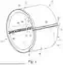
FIG. 1 shows a spatial view of a first embodiment according to the invention,
FIG. 2 shows a front view of FIG. 1,
FIG. 3 shows a sectional view A-A according to FIG. 2,
FIG. 4 shows a sectional view G-G according to FIG. 2,
FIG. 5 shows an enlarged view C according to FIG. 1,
FIG. 6 shows a sectional view E-E according to FIG. 3,
FIG. 7 shows an enlarged view D according to FIG. 3, and
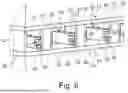
FIG. 8 shows an enlarged spatial view as a detail of a connecting region of the first embodiment according to the invention,
FIG. 9 shows a second embodiment of a tunnel lining element according to the invention,
FIG. 10 shows a spatial top view of FIG. 9,
FIG. 11 shows a sectional view A-A of FIG. 10,
FIG. 12 shows an enlarged view D of FIG. 10,
FIG. 13 shows a sectional view B-B of FIG. 11, and
FIG. 14 shows a view of a detail of a connecting section of a tunnel lining element according to the invention in the second embodiment,
FIG. 15 shows a spatial view of a third embodiment of a tunnel lining element according to the invention,
FIG. 16 shows a frontal top view of FIG. 15,
FIG. 17 shows a sectional view A-A of FIG. 16,
FIG. 18 shows a sectional view D-D of FIG. 16,
FIG. 19 shows an enlarged view C of FIG. 15,
FIG. 20 shows a sectional view B-B of FIG. 17, and
FIG. 21 shows a partially sectioned enlarged view of a connection of the third embodiment of the tunnel lining element according to the invention,
FIG. 22 shows a spatial view of a fourth embodiment of a tunnel lining element according to the invention,
FIG. 23 shows a frontal top view of FIG. 22,
FIG. 24 shows a sectional view A-A of FIG. 23,
FIG. 25 shows a sectional view D-D of FIG. 23,
FIG. 26 shows an enlarged view of detail C of FIG. 22,
FIG. 27 shows a sectional view F-F of FIG. 24,
FIG. 28 shows an enlarged view of detail G of FIG. 27, and
FIG. 29 shows an enlarged view of a detail of a connecting section according to the fourth embodiment of the tunnel lining element according to the invention.
FIGS. 1 to 29 show four embodiments according to the invention of a tunnel lining element 10 according to the invention. The tunnel lining element 10 is preferably formed here from two tunnel lining segments 11, which are preferably connected here to each other two connecting sections 12. A larger number of tunnel lining segments 11 and connecting sections 12 is possible here depending on the diameter of the tunnel lining element 10.
The number of tunnel lining segments 11 for assembling the tunnel lining element 10 may be dependent on the dimensioning with regard to size and weight of the individual tunnel lining segments 11. This may be relevant in particular with regard to the transport of said elements and the restrictions arising in the process.
The exemplary embodiments 1-4 of the invention, shown here in FIGS. 1-29 , differ with regard to the implementation of a connection 15 in the form of the connecting sections 12. Different force-fitting or integrally bonded and preferably watertight connections 15 are shown here.
According to the invention, the tunnel lining segments 11 are transported individually to the construction site and assembled there in situ to form a tunnel lining element 10 by producing the connections 15. The tunnel lining segments 10 are then brought to the starting point. Alternatively, the tunnel lining elements 10 are assembled directly at the starting point.
A press frame is provided at the starting point, which press frame, for example, advances a tunnel boring machine or a shield machine into the ground along a boring line. After the tunnel boring machine is inserted into the ground, the first tunnel lining element 10 is connected to the tunnel boring machine and advanced into the ground by the press frame, with the tunnel boring machine breaking down the ground present along the boring line. This procedure is repeated accordingly using further tunnel lining elements 10 until the tunnel boring machine has arrived at the target point along the boring line.
The individual tunnel lining segments 11 are moved either from outside the starting point, for example a pit or a section of a tunnel, into the operative region of the press frame, for example with a crane or another lifting tool, in order then to be introduced into the ground.
Alternatively, an apparatus is provided at the starting point or even as a component of the press frame, to which the individual tunnel lining segments 11 are supplied and with which the tunnel lining segments 11 are then assembled to form the tunnel lining element 10, and therefore the connection 15 can then be produced according to the embodiments of the invention that are subsequently set forth.
A further advantage of providing the individual tunnel lining segments 11 and the assembly in situ at the starting point is that supply and discharge lines do not necessarily have to be released for each individual tunnel lining element 10, and instead the tunnel lining element 10 is constructed by arranging and connecting the tunnel lining segments 11 around these lines.
Advantageously, the connection 15 is designed in such a way that said lines can both transfer the advancing forces acting on the tunnel lining element 10 in the boring direction without the connection 15 being impaired, and that the pressures and loads acting through the ground radially inward from the outside, such as internal forces/bending moments, transverse force, annular normal force, do not impair the connection 15.
It is preferably provided that the connection 15 is integrally bonded (as for example in embodiment 2 of the invention according to FIGS. 9-15) or force-fitting (as according to FIGS. 1-9 and 16-29 of embodiments 1, 3 and 4). Preferably, the connection 15 is also waterproof. Furthermore, a form-fitting connection is also possible, either by itself or in combination with one of the aforementioned connection options.
The tunnel lining segments 11 preferably have the curved shape of a circular ring segment of the tunnel lining element 10 which here is preferably annular, particularly preferably in the shape of a circular ring.
In this case, the tunnel lining segments 11 each have a curved end face 16, which is the connecting surface between the individual tunnel lining elements 10, when the tunnel lining elements 10 are introduced into the ground as previously described. Furthermore, the tunnel lining segments 11 have short sides 17, on which a first connecting element 13 and a second connecting element 14 are in each case arranged.
Depending on requirements and type of connection, the first connecting element 13 and the second connecting element 14 can be identical or different.
Furthermore, the tunnel lining segment 11 has an outer side 18 and an inner side 19.
The outer side 18 and/or the inner side 19 can be provided with a coating, for example a plastics lining.
The end faces 16, short sides 17, outer side 18 and inner side 19 form a body 20. This body 20 consists preferably of concrete, reinforced concrete, steel or plastic, but also of other materials/composite materials such as GFRP or polymer concrete.
The short sides 17 are each connected to a first and a second connecting element 13, 14.
The general shape of the individual connecting segments 11 with regard to the preferred embodiments 1-4 according to the invention is identical, but may have to be adapted to the specific individual case.
An embodiment according to the invention for the production of the lining elements 10 according to the invention, for example consisting of reinforced concrete, makes provision that a shape is provided in which the first and second connecting elements 13, 14 are arranged in such a way that they either already have a releasable connection 15 with each other or are arranged in such a way with respect to each other that they could be connected. The actually definitive connection then only takes place at or in the starting point, as previously described.
In addition, reinforcement is added to the formwork, if necessary. Subsequently, according to the design of the production and the necessary parameters in situ or in a pipe mill/precast concrete plant, concrete is introduced into the formwork until the latter is filled. Preferably, the connecting elements 13, 14 have connecting sections (not illustrated) which then produce an appropriately holding connection with the concrete of the body 20.
Preferably, the formwork is placed on one of the two surfaces, which is parallel to the end faces 16. Furthermore, the connecting elements 13, 14 and/or the upper side of the formwork preferably have openings through which air within the formwork can escape.
After the concrete has hardened, the formwork is opened accordingly and the tunnel lining segments are separated in the connection (if necessary) and removed from the formwork individually.
It is advantageously noted which tunnel lining segments 11 were produced together in the formwork, so that they can be assembled in situ accordingly again to form a tunnel lining segment 10. This ensures that the individual tunnel lining segments 11 can be optimally assembled to form a tunnel lining element 10 in situ. Possible deviations in the arrangement of a connecting section 12 consisting of a first and a second connecting element 13, 14 are not relevant as a result, since they can be assembled correspondingly easily again in situ during the production of the tunnel lining segment.
Preferably, a cuff section 21 is provided on one of the two end faces 16 of a tunnel lining segment 11, which forms a cuff seal 22 in the assembled state of the tunnel lining element 10. This is preferably shown here in all four embodiments.
Embodiment Two According to FIGS. 9-15
In this embodiment, the first connecting element 13 and the second connecting element 14 are preferably identical. They each have a basic body 30, 40. The basic bodies 30, 40 lie with their outer sides 31, 41 on each other in the connecting section 12 such that a joint 23 forms.
Depending on the requirements, the joints are welded on the inner side 24, outer side 25 and/or end face 26. This creates a connection 15, which is realized here in a correspondingly integrally bonded manner.
Alternatively, the upper sides 31, 41 can be adhesively bonded together to form a connection 15, also in an integrally bonded manner.
Another alternative makes provision for contact welding of the basic bodies 30, 40 on their upper sides 31, 41, in order to produce the connection 15, likewise in an integrally bonded manner.
Preferably, the weld seam 27 is provided on the inner side 24 and weld seam 28 on the outer side 25 in order to provide both a sufficient tightness in the connecting section 12 and to transmit tensile and compressive forces and shearing forces when pressing in the assembled tunnel lining elements 10 during the insertion into the ground.
Embodiment Three According to FIGS. 15-21
At the basic bodies 40, 41 webs 32, 42 are provided which are preferably arranged transversely here and on which horizontal flange sections 32, 42, which are preferably arranged on both sides here, are arranged. Bores 34, 44 are arranged in the flange sections. The bores 34, 44 are arranged in such a way that they align in the assembled state such that a connecting element/clamping element, here a screw 50, can be inserted through the bores 34, 44. The connecting element/clamping element furthermore comprises a nut 51 which can be screwed onto a threaded section 52. Screwing of the nut 51 onto the threaded portion 52 against the underside 45 of the flange section 43 causes a screw head 53 to be tightened to the upper side 35 of the flange section 33 such that a preload is generated between the two flange sections 33, 43. The upper side 46 of the flange section 43 and the underside 36 of the flange section 33, which lie opposite each other, are either in contact with each other or a gap 29 remains between them, in particular in the region remote from the edge, depending on the embodiment. For this purpose, spacers 60, 61 each standing on the outer side 41, 31 are provided on the inner side 24 and on the outer side 25. Depending on the height of the spacers 60, 61, the flange sections 33, 43 are in contact or there is a gap 29 between them. If there is correspondingly a gap 29, it is particularly easy to introduce a defined preload into the connection.
The webs 32, 42 are arranged radially from the inner side 24 toward the outer side 25, preferably parallel to the end face 26. Furthermore, the bores 34, 44 preferably form a radial row from the inner side 24 toward the outer side 25.
If the height of the spacers 60, 61 is longer than the height of the webs 32, 42 and the height of the flange sections 33, 43, the gap 29 is formed in the clamped state. It is advantageous in this connection that the tensile and compressive forces are respectively transmitted in a defined manner on the outer side 25 and the inner side 24 in the connecting section 12 and in the connection 15.
The spacers 61 are preferably provided in the region of the flanges 33, 43 on the inner side 24 in order to reach openings 62 such that the nuts 51 and screw heads 53 of the connecting element can be held or moved with tools in order to bring about the clamping.
Shearing forces acting in the connection 15 are removed if there is a gap 29 between the spacers 60, 61 and the outer sides 31, 41 of the basic bodies 30, 40 and the screws 50 as a connecting element.
In addition, for the transmission of thrust forces, at least one protrusion, preferably in the form of a thrust cam, can be provided in the connection 15 or on the at least one connecting element 13 or 14, and at least one recess for producing a form fit in the connection or between the connecting elements 13, 14 of the tunnel lining segments 11 can be provided on the opposite side in the connection 15 or on the at least one further connecting element 14 or 13.
If there is no gap 29, if the spacers 60, 61 in height are equal to or smaller than the height of the webs 32, 42 and flange sections 43, 33, a frictional connection between the underside 36 and the upper side 46 of the flange sections 33, 43 is brought about by the connecting elements/clamping elements, here screws 50 and nuts 51. The shearing forces are then transmitted accordingly via said frictional connection, as are the tensile and compressive forces that act in the connection 15.
The spacers 61 on the outer side 25 are preferably provided as a continuous body along the outer side 25 and are preferably connected, preferably in an integrally bonded manner, to one of the basic bodies 30, 40. After the tunnel lining segments 11 are assembled to form the tunnel lining element 10 and the connection 15 is provided, a connection to the other basic body 30, 40, preferably in an integrally bonded manner, can then also be produced. This can bring about sealing of the connection with respect to the outer side 18 and water in the ground. This also applies to other embodiments according to the invention that use spacers.
Alternatively or in addition, a sealing element can also be provided in this region.
For corrosion protection and for the production of a continuous surface on the inner side 19 of the tunnel lining element 10, the region of the connecting section can be filled, for example, with mortar or other materials. This also applies to other embodiments according to the invention.
Embodiment One According to FIGS. 1-9
The connecting section 12 of a tunnel lining element 10 according to the first embodiment of the invention has a first connecting element 13 with a basic body 30 and a second connecting element 14 with a basic body 40. Webs 32, 42, on which a flange section 33, 43 is provided, here preferably horizontally to both sides of the webs 32, 42, are arranged on the basic bodies 30, 40. The webs 32, 42 are arranged vertically, preferably radially from an inner side 24 to an outer side 25 of the connecting section 12.
Between the basic bodies 30, 40, spacer 60 is provided on the inner side 24 and a preferably continuous spacer 61 is provided on the outer side 25. Depending on whether the spacers 60, 61 are higher than the height of the webs 32, 42 and the height of the flange sections 33, 43, the underside 36 of the flange section 33 and the upper side 46 of the flange section 43 lie on top of each other in the assembled state, or there is a gap 29 between the flange sections 33, 43.
For the clamping of the flange sections 33, 43, an enclosing element, here preferably a clamp 55, which is preferably designed in a C-shaped manner here, is provided. The clamp has a rear wall 56 and two protrusions 57, 58 which are arranged parallel to each other and here are preferably horizontal. At one of the protrusions 57, 58, here preferably the lower protrusion 58, a nose 59 which extends in the direction of the interior of the clamp 55 is preferably provided.
In the upper protrusion 57, bores 54 are preferably provided here. Preferably, a plurality of bores 54 arranged in a row over the length of the clamp 55 are provided in the upper protrusion.
Clamping elements 63, here preferably a screw, particularly preferably a hexagon socket screw, are introduced into the bores 54.
If the tunnel lining segments 11 are arranged to form a tunnel lining element 10 and the connecting sections 12 are prepared for the fastening, the clamps 55 are applied to the upper side 35 of the corresponding upper flange section such that the clamp 55 with its two protrusions 57, 58 and the rear wall 56 embraces the flange sections 33, 43. The screws are then screwed into the bores 54 as connecting elements 63 (these may also already be inserted in the bores 54 of the clamps 55) so that the screws come into contact with the upper side 35 of the upper flange section 33. By further screwing in, the clamp 55 is moved upward such that the nose 59 comes into connection with the underside 45 of the lower flange section 43. Further screwing in of the screws as preloading elements 63 causes the flange sections to be clamped/preloaded against one another if there is no gap 29 between the underside 36 of the flange section 33 and the upper side 46 of the flange section 43. If there is a gap 29, the spacer elements 60, 61 are clamped against the basic bodies 40, 30. In this way, it is easily possible to introduce a preload into the connection in a defined manner.
In this way, shearing forces or pressure and tension can be transmitted via the connecting section 12.
The spacers 60, 61 can in turn be connected to one of the basic bodies, preferably in an integrally bonded manner. In addition, the spacer 61 on the outer side 25 can be connected, likewise in an integrally bonded manner, to the other basic body 30, 40 for the sealing. Alternatively or additionally, a sealing element can also be provided.
Furthermore, on the inner side 19 after assembly and production of the connection 15, the connecting section 12 can be filled with mortar or other materials to provide a uniform inner side 19.
Embodiment Four According to FIGS. 22-29
In the fourth embodiment, the connecting section 12 likewise has a first connecting element 13 and second connecting element 14. Said connecting elements respectively have a basic body 30 and a basic body 40. A web 32, 42 is provided in each case radially from the inner side 24 to the outer side 25. At the webs 32, 42, a flange section 33, 43 is in each case provided horizontally parallel to the outer side 31, 41 of the basic bodies 30, 40. Preferably, the flange sections 33, 43 extend to both sides of the webs 32, 42.
Preferably, the flange section 33 has a protrusion 47, which is arranged in the direction of the upper side 46 of the lower flange section 43.
A wedge element 47 is mounted on the upper side 46 of the lower flange section 43.
On the flange section 33, preferably at the protrusion 37, there is an angular element 38 which has a side 39 provided parallel to the web 32 and a horizontal engaging element 49 provided parallel to the outer side 41 of the basic body 40. The angular element 38 is preferably releasably arranged on the flange section 33/protrusion 37. Preferably, the angular element 38 is screwed to the flange section 33/the protrusion 37.
Between the underside 36 of the flange section 33 and the upper side 46 of the flange section 43, a cavity/gap 48 is provided, which is delimited on one side by the web 42 and on the other side by the protrusion 37. A clamping element 64 can be inserted in said cavity 48.
The clamping element 64 has an elongate section 65, which is arranged on a head plate 66.
The underside of the elongate section 65 is formed correspondingly to the wedge element 47.
The wedge element 47 has latching protrusions 67, which are also provided analogously on the underside of the elongate section 65 as corresponding latching protrusions 68.
By insertion of the clamping element 64 or its elongate section 65 into the space 48 until the latching protrusions 67, 68 intermesh, the upper side 69 of the engaging element 49 pushes the flange sections 33, 43 apart such that the two engaging elements 13, 14 are latched together. This results in clamping between them, via which the forces introduced correspondingly into the connecting section 12 can be dissipated.
Claims
1-29. (canceled)
30. A tunnel lining element comprising at least two tunnel lining segments, with a body, wherein each tunnel lining segment has a first and a second side at which the at least two tunnel lining segments are connected to each other along the corresponding first and second sides to form a closed element, wherein at least one connecting element is arranged on the first side and on the second side of the tunnel lining segment to form the connection between the at least two tunnel lining segments, wherein the connecting elements:
comprise at least one flange;
the flanges on corresponding first and second sides are arranged opposite each other when the tunnel lining segments are joined;
an enclosing element is disposed to surround the two opposite flanges, wherein
there is a force fitting connection between the flanges and the enclosing element.
31. The tunnel lining element as claimed in claim 30, wherein the enclosing element is a C-shaped element with a rear wall and an upper protrusion and a lower protrusion,
32. The tunnel lining element as claimed in claim 31, wherein at least one bore is provided in the upper protrusion, into which a clamping element can be inserted, in order to provide the force-fitting connection between the connecting elements.
33. The tunnel lining element as claimed in claim 30, wherein the enclosing element is an angular element fastened to a flange section of one flange and enclosing the oppositely arranged flange.
34. The tunnel lining element as claimed in claim 30, wherein a cavity for the insertion of a clamping element is provided between the flanges.
36. The tunnel lining element as claimed in claim 33, wherein at least one bore is provided in the flange of the first connecting element, into which a clamping element can be inserted, in order to provide the force-fitting connection between the connecting elements.
37. The tunnel lining element as claimed in claim 33, wherein a face of the flange is a wedge-shaped surface.
38. The tunnel lining element as claimed in claim 37, wherein protrusions are provided in the wedge-shaped surface in order to provide a form-fitting connection to a clamping element.
39. The tunnel lining element as claimed in claim 37, wherein the clamping element has a wedge shape which is consistent with the wedge-shaped surface of the flange section.
40. The tunnel lining element as claimed in claim 30, wherein there is a gap between the flange sections in the state of the force-fitting connection.
41. The tunnel lining element as claimed in claim 30, wherein at least one spacer is provided between the base bodies.
42. The tunnel lining element as claimed in claim 41, wherein the at least one spacer is fixedly connected on its outer side to one of the base bodies.
43. The tunnel lining element as claimed in claim 41, wherein at least one spacer is provided on a long inner side and at least one spacer is provided on a long outer side.
44. The tunnel lining element as claimed in claim 30, wherein the base body is fixedly connected to the body.
45. The tunnel lining element as claimed in claim 30, wherein the body is composed of reinforced concrete, in particular polymer concrete, steel, composite materials, GFRP, or plastic.
46. The tunnel lining element as claimed in claim 30, wherein the tunnel lining element is annular, and in that the tunnel lining segment is in the form of a circular segment.
47. The tunnel lining element as claimed in claim 30, wherein the connection is watertight.
48. The tunnel lining element as claimed in claim 47, wherein the watertightness is provided by a sealing element between the base bodies or between a base body and a spacer element, insertion and/or application of a sealant, or an integrally bonded connection.
49. The tunnel lining element as claimed in claim 30, wherein, for the transmission of thrust forces, at least one protrusion, preferably in the form of a thrust cam, is provided in the connection or on the at least one connecting element, and at least one recess for producing a form fit in the connection or between the connecting elements of the tunnel lining segments is provided on the opposite side in the connection or on the at least one further connecting element.
Images & Drawings included:


Sources:
- United States Patent and Trademark Office - verify current appl. status at the USPTO↗
Similar patent applications:
Recent applications in this class:
- » 20250067177 2025-02-27
CONTROL APPARATUS AND METHOD FOR BUOYANCY ADJUSTMENT OF SHIELD TUNNEL SEGMENTS - » 20210079791 2021-03-18
Removable and replaceable anchored tunnel gasket - » 20180058216 2018-03-01
COUPLER DEVICE AND ASSEMBLY - » 20150125215 2015-05-07
METHOD FOR CONSTRUCTING A TUNNEL COURSE, AND STRUCTURAL ELEMENT FOR USE BY THE METHOD - » 19209820 2025-09-02
Articulated prestressing tensioning device for shield tunnels and reinforcement method thereof