Overhead Valve Internal Combustion Engine
US20260146547A1
2026-05-28
19/206,419
2025-05-13
Smart Summary: An overhead valve internal combustion engine has a main part called the engine block, with cylinder heads attached on top. It features special ports for air intake and exhaust, connecting to manifolds. The engine uses pushrod assemblies to operate the intake and exhaust valves, which help control the flow of air and gases. One of these pushrod assemblies is designed with joints that allow for movement, making it easier to operate the valves. Additionally, there are guides that help keep these jointed pushrods in the right position as they work. 🚀 TL;DR
Abstract:
An overhead valve (OHV) internal combustion engine includes an engine block. Cylinder heads are mounted on the engine block. Intake and exhaust ports connect to intake and exhaust manifolds. Intake pushrod assemblies engage intake valve rocker arms and valve lifters. Exhaust pushrod assemblies engage exhaust valve rocker arms and exhaust valve lifters. One of the intake and exhaust pushrod assemblies is a jointed pushrod assembly. The jointed pushrod assembly includes an upper pushrod segment that engages one of the intake and exhaust valve rocker arms. A lower pushrod segment engages one of the respective intake and exhaust valve lifters. Complementary joint members pivotally engage each other and can include an angle of less than 180 degrees. At least one pushrod guide assembly is mounted on one of the engine block and each head, and defines at least one passage that guides the complementary joint members.
Applicant:
Interested in similar patents?
Get notified when new applications in this technology area are published.
Classification:
F01L1/146 » CPC main
Valve-gear or valve arrangements, e.g. lift-valve gear; Transmitting gear between valve drive and valve; Tappets ; Push rods Push-rods
F01L1/053 » CPC further
Valve-gear or valve arrangements, e.g. lift-valve gear; Valve drive by means of cams, camshafts, cam discs, eccentrics or the like; Camshafts overhead type
F01L1/14 IPC
Valve-gear or valve arrangements, e.g. lift-valve gear; Transmitting gear between valve drive and valve Tappets ; Push rods
Description
FIELD
Various embodiments of an overhead valve (OHV) internal combustion engine, a head for an OHV engine, and a pushrod assembly for an OHV engine are described herein.
BACKGROUND
Overhead valve (OHV) engines are piston engines with valves located in a cylinder head above the combustion chambers. In such engines, one or more camshafts are in the engine block. Pushrods are interposed between the camshaft and valve rockers and are reciprocally driven by the camshaft. In turn, the valve rockers are reciprocally driven against the bias of valve springs to open and close inlet and exhaust valves. Pushrod assemblies include pushrods that can be subjected to significant stresses. This is the case where the geometry of the engine requires that the pushrods be long. Longer pushrods are generally heavier than shorter pushrods per unit of length because the higher stresses experienced by longer pushrods necessitates additional cross-sectional area of the pushrods. The reason for this is associated with moments of force. A moment of force, M, can be calculated by M=r×F, where r is a distance from a reference point, such as an end of a pushrod and F is a force vector acting at any point in a body, such as a force vector that may act at the end of a pushrod, in operation. This means that for greater values of (r), the length of the pushrod, the greater the moment of force (M) for a constant force vector (F). As is known, tensile and compressive stresses increase proportionally with M. Thus, tensile and compressive stresses are higher in longer pushrods than they are in shorter pushrods for the same forces applied at the ends of the pushrods.
OHV engines may have a simpler design than OHC engines. The configuration of OHV engines may result in fewer moving parts compared to OHC engines, where the camshaft(s) is in the cylinder head and is driven by a timing belt or chain. Fewer moving parts generally mean fewer points of potential failure, contributing to the overall durability and longevity of OHV engines. This simplicity may also make OHV engines easier and less expensive to maintain.
The simpler design of OHV engines may not only reduce manufacturing costs compared to those of OHC engines but may also make repairs and maintenance more straightforward and less costly. This cost advantage may be significant for applications where budget constraints are a concern, such as in certain types of vehicles and machinery.
The design of OHV engines may allow for more compact and lighter engines compared to overhead cam (OHC) engines. The cam-in-block of OHV engines means that the cylinder head may be smaller than that of OHC engines, which reduces the overall size and weight of the engine compared to an OHC engine. This compactness may be beneficial in applications where space and weight are critical factors, such as in certain types of vehicles and equipment.
The design of the valve train in OHV engines may allow for better air and fuel mixture at lower engine speeds than OHC engines, which translates to higher torque at the lower end of the RPM range. This characteristic may make OHV engines particularly well-suited for applications that require strong low-end performance, such as in trucks, sport-utility vehicles, and certain types of performance vehicles.
As set out above, one of the advantages of OHV engines may be their compactness. However, this can cause complications in V-type engines, such as high-capacity V8 engines.
A conventional, prior art, OHV V8 engine includes a crankshaft and a camshaft that is geared to the crankshaft. The camshaft is positioned above the crankshaft in a valley of an engine block that has a V configuration. Pushrods are engaged with valve lifters or tappets that are driven reciprocally by the camshaft. The pushrods project into respective cylinder heads to engage and drive intake and exhaust rocker arms. To do so, the pushrods bypass intake ports.
OHV V8 engines that are used for racing can have modified heads. The modifications can include enlarged intake ports, or intake ports that are spread apart. This can result in constraints on other engine components, such as valve lifters and pushrods. Conventionally, a direct line can be drawn from a valve lifter to a corresponding rocker arm. Enlarged or spread intake ports can interfere with that line.
SUMMARY
Various embodiments of an overhead valve (OHV) internal combustion engine comprise:
-
- an engine block with at least one cylinder;
- at least one cylinder head mounted on the engine block, the, or each, cylinder head including intake and exhaust ports for connection to intake and exhaust manifolds, respectively;
- at least one intake pushrod assembly that engages a respective intake valve rocker arm at an upper end and a respective intake valve lifter at a lower end;
- at least one exhaust pushrod assembly that engages a respective exhaust valve rocker arm at an upper end and a respective exhaust valve lifter at a lower end, at least one of the intake and exhaust pushrod assemblies being a jointed pushrod assembly and comprising:
- an upper pushrod segment for engagement with one of the respective intake and exhaust valve rocker arms at said upper end;
- a lower pushrod segment for engagement with one of the respective intake and exhaust valve lifters at said lower end; and
- complementary joint members defined by lower and upper end portions of the upper and lower pushrod segments, respectively, that are engageable with each other so that they can include an angle of less than 180 degrees; and
- at least one pushrod guide assembly mounted on one of the engine block and the head, the, or each, pushrod guide assembly defining at least one passage, the complementary joint members of the, or each, jointed pushrod assembly being received in the passage to be reciprocally guided in the passage.
The passage may be positioned so that the complementary joint members can be reciprocally guided in the passage while the pushrod segments include the angle of less than 180 degrees.
The complementary joint members may comprise complementary bearing members that are configured for nesting arrangement with respect to each other.
One of the bearing members may define a concave bearing surface, and the other bearing member may define a convex surface.
The intake pushrod assembly may be the jointed pushrod assembly. Alternatively, the exhaust pushrod assembly may be the jointed pushrod assembly.
The, or each, pushrod guide assembly may include a guide member and a bearing sleeve extending at least partially through the guide member, the bearing sleeve defining the passage.
The, or each, pushrod guide assembly may include a pushrod guide member that is arranged on the, or each respective head, the, or each, pushrod guide member defining the at least one passage.
A straight line between said one of the respective intake and exhaust valve rocker arms and said one of the respective intake and exhaust valve lifters may be obstructed by an intake port. The passage may be generally aligned with said one of the respective intake and exhaust valve rocker arms and the included angle may allow the jointed pushrod assembly to accommodate the intake port.
The included angle may be between 170 degrees and 178 degrees.
Various embodiments of a pushrod assembly for an overhead valve (OHV) internal combustion engine that includes an engine block with at least one cylinder and at least one cylinder head mounted on the engine block, the, or each, cylinder head including intake and exhaust ports for connection to intake and exhaust manifolds, respectively, comprise:
-
- an upper pushrod segment for engagement with one of intake and exhaust valve rocker arms of the engine at an upper end;
- a lower pushrod segment for engagement with one of intake and exhaust valve lifters of the engine at a lower end; and
- complementary joint members defined by lower and upper end portions of the upper and lower pushrod segments, respectively, that are pivotally engageable with each other to facilitate orientation of the upper and lower pushrod segments with respect to each other such that they can include an angle of less than 180 degrees.
The complementary joint members may comprise first and second complementary bearing members that are configured for nesting arrangement with respect to each other.
The first bearing member may define a concave bearing surface, and the second bearing member may define a convex bearing surface. The convex surface may be partially enclosed by the concave surface to allow swivelling of the pushrod segments relative to each other.
The first and second bearing members may form a ball and socket joint.
The pushrod assembly may include a pushrod guide assembly that is mounted on one of the engine block and the, or each, head of the engine. The pushrod guide assembly may define a passage. The complementary joint members may be received in the passage that can be positioned so that the complementary joint members can be reciprocally guided in the passage.
The passage may be positioned so that the segments are retained in an angular orientation relative to each other that is less than 180 degrees while being reciprocally guided in the passage.
The pushrod guide assembly may include a pushrod guide member and a bearing sleeve extending through the guide member and defining the passage.
The first bearing member may define a cylindrical bearing surface that is in sliding engagement with the bearing sleeve.
Each pushrod segment may define an oil passage. The oil passages of respective pushrod segments may be in fluid communication with each other with the joint members being configured to permit the egress of oil for lubrication of the joint members and the passage.
Various embodiments of a cylinder head for an overhead valve (OHV) internal combustion engine that includes an engine block, at least one intake pushrod assembly for engaging a respective intake valve rocker arm of the cylinder head, at least one exhaust pushrod assembly for engaging a respective exhaust valve rocker arm of the cylinder head, at least one of the intake and exhaust pushrod assemblies for each cylinder being a jointed pushrod assembly and comprising an upper pushrod segment for engagement with one of the respective intake and exhaust rocker arms at said upper end, a lower pushrod segment for engagement with one of the respective intake and exhaust valve lifters at said lower end, and complementary joint members defined by lower and upper end portions of the upper and lower pushrod segments, respectively, that are engageable with each other to facilitate orientation of the upper and lower pushrod segments with respect to each other so that they can include an angle of less than 180 degrees, the cylinder head comprising:
-
- at least one pushrod guide assembly defining a passage, complementary joint members of jointed pushrod assemblies being received in respective passages, and the passages being positioned to reciprocally guide the complementary joint members.
Various embodiments of an overhead valve (OHV) internal combustion engine comprise:
-
- an engine block with at least one cylinder;
- a cylinder head mounted on the engine block, the cylinder head including intake and exhaust ports for connection to intake and exhaust manifolds, respectively;
- at least one intake pushrod assembly that engages a respective intake valve rocker arm; and
- at least one exhaust pushrod assembly that engages a respective exhaust valve rocker arm; at least one of the intake and exhaust pushrod assemblies being a jointed pushrod assembly and comprising:
- a lower pushrod segment for engagement with a valve lifter of the engine at a lower end;
- an upper pushrod segment for engagement with one of the intake and exhaust valve rocker arms at an upper end; and
- complementary joint members defined by lower and upper end portions of the upper and lower pushrod segments, respectively, that are engageable with each other to facilitate swivelling of the upper and lower pushrod segments with respect to each other, wherein
- the head includes at least one pushrod guide assembly, the, or each, pushrod guide assembly defining a passage, the complementary joint members of the, or each, jointed pushrod assembly being received in a respective passage that is positioned so that the complementary joint members can be reciprocally guided in the passage.
Various embodiments of an overhead valve (OHV) internal combustion engine comprise:
-
- an engine block with two banks of cylinders in a V configuration;
- cylinder heads mounted on respective banks of cylinders, each cylinder head including intake and exhaust ports for connection to intake and exhaust manifolds, respectively;
- intake pushrod assemblies that engage intake valve rocker arms for respective cylinders;
- exhaust pushrod assemblies that engage exhaust valve rocker arms for respective cylinders, at least one of the intake and exhaust pushrod assemblies for each cylinder being a jointed pushrod assembly and comprising:
- a lower pushrod segment for engagement with a valve lifter of the engine at a lower end; and
- an upper pushrod segment for engagement with one of the intake and exhaust valve rocker arms at an upper end; and
- complementary joint members defined by lower and upper end portions of the upper and lower pushrod segments, respectively, that are engageable with each other to facilitate swivelling of the upper and lower pushrod segments with respect to each other; and
- pushrod guide assemblies arranged below respective intake ports, each pushrod guide assembly defining a passage, the complementary joint members of the jointed pushrod assemblies being received in respective passages, and the passages being positioned with respect to respective intake ports so that the upper pushrod segments are offset with respect to the respective intake ports.
Various embodiments of a pushrod assembly for an overhead valve (OHV) internal combustion engine having an engine block with at least one cylinder, a cylinder head mounted on the engine block, the cylinder head including intake and exhaust ports for connection to intake and exhaust manifolds, respectively, at least one pushrod guide assembly mounted on the engine block, each pushrod guide assembly defining a passage, comprise:
-
- a lower pushrod segment for engagement with a valve lifter of the engine at a lower end;
- an upper pushrod segment for engagement with one of intake and exhaust valve rocker arms at an upper end; and
- complementary joint members defined by lower and upper end portions of the upper and lower pushrod segments, respectively, that are engageable with each other to facilitate swivelling of the upper and lower pushrod segments with respect to each other, the complementary joint members being received in the passage of the pushrod guide assembly to be reciprocally guided in the passage.
Various embodiments of a pushrod assembly for an overhead valve internal combustion V engine having an engine block with two banks of cylinders in a V configuration, cylinder heads mounted on respective banks of cylinders, each cylinder head including intake and exhaust ports for connection to intake and exhaust manifolds, respectively, and pushrod guide assemblies mounted on the engine block below respective intake ports, each pushrod guide assembly defining a passage, the passages being offset with respect to respective intake ports, comprise:
-
- a lower pushrod segment for engagement with a valve lifter of the engine at a lower end;
- an upper pushrod segment for engagement with one of intake and exhaust valve rocker arms at an upper end; and
- complementary joint members defined by lower and upper end portions of the upper and lower pushrod segments, respectively, that are engageable with each other to facilitate swivelling of the upper and lower pushrod segments with respect to each other, the complementary joint members being received in respective passages so that the upper pushrod segment is offset with respect to one of the intake ports.
Various embodiments of a cylinder head for an overhead valve (OHV) internal combustion engine that includes an engine block, at least one intake pushrod assembly for engaging a respective intake valve rocker arm of the cylinder head, at least one exhaust pushrod assembly for engaging a respective exhaust valve rocker arm of the cylinder head, at least one of the intake and exhaust pushrod assemblies for each cylinder being a jointed pushrod assembly and having a lower pushrod segment for engagement with a valve lifter of the engine at a lower end, an upper pushrod segment for engagement with one of the intake and exhaust valve rocker arms at an upper end, and complementary joint members defined by lower and upper end portions of the lower and upper pushrod segments, respectively, that are engageable with each other to facilitate swivelling of the upper and lower pushrod segments with respect to each other, comprise:
-
- intake and exhaust ports for connection to intake and exhaust manifolds, respectively; and
- at least one pushrod guide assembly defining a passage, complementary joint members of jointed pushrod assemblies being received in respective passages, and the passages being positioned to reciprocally guide the complementary joint members.
Various embodiments of a cylinder head for an overhead valve (OHV) internal combustion engine that includes an engine block with two banks of cylinders in a V configuration, the cylinder head being mountable on one bank of cylinders, intake pushrod assemblies for engaging respective intake valve rocker arms of the cylinder head, exhaust pushrod assemblies for engaging exhaust valve rocker arms of the cylinder head, one of the intake and exhaust pushrod assemblies for each cylinder being a jointed pushrod assembly and having a lower pushrod segment for engagement with a valve lifter of the engine at a lower end, an upper pushrod segment for engagement with one of the intake and exhaust valve rocker arms at an upper end, and complementary joint members defined by lower and upper end portions of the lower and upper pushrod segments, respectively, that are engageable with each other to facilitate swivelling of the upper and lower pushrod segments with respect to each other, comprises:
-
- intake and exhaust ports for connection to intake and exhaust manifolds, respectively; and
- pushrod guide assemblies arranged below respective intake ports, each pushrod guide assembly defining a passage, the complementary joint members being received in respective passages, and the passages being positioned with respect to respective intake ports so that the upper pushrod segments are offset with respect to the respective intake ports.
BRIEF DESCRIPTION OF THE DRAWINGS
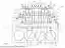
FIG. 1 is a three-dimensional view of an embodiment of an OHV internal combustion engine, with conventional parts removed for clarity.
FIG. 2 is a view of part of the engine of FIG. 1.
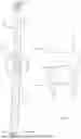
FIG. 3 is a three-dimensional view of an embodiment of a pushrod assembly.
FIG. 4 is a detailed view of detail A in FIG. 3.
FIG. 5 is a side view of the pushrod assembly of FIG. 3 in a bearing sleeve.
FIG. 6 is a three-dimensional view of the pushrod assembly of FIG. 3 in the bearing sleeve.
FIG. 7 is a part-sectioned side view of an embodiment of the pushrod assembly of FIG. 3 in a pushrod guide assembly that incorporates the bearing sleeve.
FIG. 8 is an exploded view of the pushrod assembly of FIG. 3.
FIG. 9 is a view of detail B in FIG. 8.
FIG. 10 is a three-dimensional view of an embodiment of an engine, with covers and valve rockers removed for clarity.
FIG. 11 is a part-sectioned view of part of the engine of FIG. 10.
FIG. 11a is a view of detail C in FIG. 11.
FIG. 12 is a three-dimensional view of an embodiment of a pushrod assembly in a raised position.
FIG. 13 is a three-dimensional view of an embodiment of a pushrod assembly in a lowered position.
FIG. 14 shows an embodiment of a pushrod assembly in an engine.
FIG. 15 shows an embodiment of a pushrod assembly in a raised position in an engine.
FIG. 16 shows an embodiment of a pushrod assembly in an intermediate position in an engine.
FIG. 17 shows an embodiment of a pushrod assembly in a lowered position in an engine.
DETAILED DESCRIPTION
In FIG. 1, reference numeral 10 generally indicates an embodiment of an OHV internal combustion engine. The engine 10 is shown without many components for the sake of clarity. The components that have not been shown would be readily ascertained by a person of ordinary skill in the field.
The engine 10 is a V8 engine with an engine block 12 having two banks of four cylinders 14.1, 14.2, 14.3, 14.4, with the engine block 12 having a V configuration. Embodiments of the engine can have more, or less cylinders. For example, the engine can be a V6 or a V12 engine. In other examples, the engine can have any number of cylinders in an inline configuration. Such an engine has a block with an inline configuration.
The engine 10 has two heads 16, one of which is shown mounted on the block 12, in a conventional manner. The other head 16 is not shown, for the purpose of clarity. However, it is to be understood that the head 16 could be that of an engine with just one head, for example, an inline four-cylinder engine. In that case, the head 16 and associated components could be provided for that inline four-cylinder engine.
Each head 16 has four intake ports 20.1, 20.2, 20.3, 20.4. The heads 16 are performance heads, such as those used for racing, wherein the intake ports 20.1-20.4 are larger than intake ports of conventional heads. As is conventional, the two intake ports 20.1, 20.2 are positioned in a side-by-side manner, while the two intake ports 20.3, 20.4 are positioned in a side-by-side manner. It is envisaged that embodiments of the invention are applicable to performance heads in which the intake ports can be spread apart for performance-enhancing reasons, such as improving heat conduction. Embodiments of the invention are also applicable to conventional heads with conventionally sized intake ports.
Each head 16 has four intake rocker arms 24.1, 24.2, 24.3, 24.4, and four exhaust rocker arms 26.1, 26.2, 26.3, 26.4. The intake ports 20.1, 20. 2 are interposed, along a crank rotation axis 19, between the intake rocker arms 24.1, 24.2, and the intake ports 20.3, 20.4 are interposed between the intake rocker arms 24.3, 24.4. In alternative embodiments, the intake ports 20.1, 20.2 could be interposed between two exhaust rocker arms, and the intake ports 20.3, 20.4, could be interposed between two exhaust rocker arms.
An intake valve lifter 22.1 and an exhaust valve lifter 22.2 are associated with each cylinder 14.1-14.4. The valve lifters 22.1, 22.2 project through openings 18.1, 18.2, respectively, in the block 12, and are positioned so that the intake ports 20.1, 20.2 are interposed radially with respect to the crank rotation axis 19, between the valve lifters 22.1 of the cylinders 14.1, 14.2, and the rocker arms 24.1, 24.2, and the intake ports 20.3, 20.4 are interposed radially with respect to the crank rotation axis 19, between the valve lifters 22.1 of the cylinders 14.3, 14.4, and the rocker arms 24.3, 24.4.
When the heads 16 are mounted on the block 12, conventional pushrod assemblies 28 are interposed between the valve lifters 22.2 and respective exhaust rocker arms 26.1-26.4 (FIG. 2). In this embodiment, the intake ports 20.1-20.4 are enlarged. As a result, the intake ports 20.1-20.4 are positioned at least partially over respective valve lifters 22.1. Straight lines between each intake rocker arm 24.1-24.4 and the respective valve lifters 22.1 are obstructed by an intake port 20.1-20.4. As a result, it is not possible for straight, conventional pushrods to be interposed between respective valve lifters 22.1 and inlet rocker arms 24.1-24.4. It follows that the head 16, which may be a performance head, would not be compatible with the engine block 12.
To address this, the engine 10 includes eight jointed intake pushrod assemblies 30 that are configured to bypass respective intake ports 20.1-20.4 to be interposed, radially with respect to the crank rotation axis 19, between respective intake rocker arms 24.1-24.4 and valve lifters 22.1. Detail of the pushrod assembly 30 is shown in FIGS. 4 to 9. It will be appreciated that engines with more, or less cylinders will have correspondingly more or less of the pushrod assemblies 30. It is envisaged that the pushrod assemblies 30 can be likewise interposed between respective exhaust rocker arms 26.1-26.2 and valve lifters 22.1 or 22.2. Thus, in various embodiments, the pushrod assemblies 28 can be replaced by the jointed pushrod assemblies 30.
The pushrod assembly 30 includes a lower pushrod segment 32 for engagement with the intake valve lifter 22.1, at a lower end. The lower pushrod segment 32 has a conventional ball formation or ball 34 (FIG. 3) at its lower end to engage the intake valve lifter 22.1 in a conventional manner.
The pushrod assembly 30 includes an upper pushrod segment 36 for engagement with the intake rocker arm 24.1. The upper pushrod segment 36 has a conventional ball formation or ball 40 at the upper end to engage the intake rocker arm 24.1 in a conventional manner.
Complementary joint members are defined by lower and upper end portions of the lower and upper pushrod segments 32, 36, respectively, that are pivotally engageable with each other so that they can include an angle of less than 180 degrees. This allows the pushrod assemblies 30 to bypass the intake ports 20.1-20.4 while still being reciprocally displaced by the associated valve lifter. The joint members of each pushrod assembly 30 are complementary bearing members that are configured for nesting arrangement with each other.
The bearing member of the lower segment 32 is a cup formation or socket member 38 with a concave bearing surface in the form of an internal, curved, or spherical bearing surface 39 (FIG. 9). The bearing member of the upper segment 36 is a ball formation or ball 49, with a corresponding convex bearing surface in the form of a curved or spherical surface that is received in the socket member 38. Thus, the bearing members define a ball and socket joint 41. It follows that the segments 32, 36 have three degrees of rotational movement with respect to each other. This allows the segments 32, 36, to be angled in any plane relative to each other, depending on the orientation of the valve lifter and the associated rocker arm with respect to each other and also, where applicable, the need to accommodate the intake ports or some other obstruction that may exist between the valve lifter and the rocker arm.
Four pushrod guide assemblies 42.1, 42.2, 42.3, 42.4 are mounted on the engine block 12 below respective intake ports 20.1-20.4. Each pushrod guide assembly 42.1-42.4 defines a passage 44 (FIG. 7). The joints 41 are received in respective passages 44. The passages 44 are positioned with respect to respective intake ports 20.1-20.4 so that the upper pushrod segments 36 are offset with respect to the respective intake ports 20.1-20.4, and the upper and lower pushrod segments 36, 32 include an angle of less than 180 degrees. Thus, each joint 41 can be reciprocally guided in a respective passage 44 while the pushrod segments 32, 36 include the angle of less than 180 degrees. The included angle is such that the intake ports are accommodated. For example, the included angle can be between 170 degrees and 179 degrees. In certain embodiments the range can be greater to accommodate a geometry of the engine.
Each pushrod guide assembly 42.1-42.4 includes a guide member 46 and a bearing sleeve 48 extending at least partially through the guide member to be positioned in the guide member 46, the bearing sleeve 48 defining the passage 44. The guide members 46 of the assemblies 42.1, 42.2 and the guide members 46 of the assemblies 42.3, 42.4 can be defined by a one-piece member, respectively. In that case, two one-piece members can span an area between and below opposite sides of the intake ports 20.1, 20.2 and the intake ports 20.3, 20.4, respectively, as shown in FIG. 1. Alternatively, the guide members 46 of respective assemblies 42.1-42.4 can be discrete. The guide members 46 can be welded onto a wall of the head 16. Alternatively, the guide members 46 can be cast or machined during fabrication of the head 16 to form part of the head 16. In a further example, the guide members 46 can be fastened to the wall of the head 16 with suitable fasteners.
The bearing sleeve 48 and the socket member 38 are configured so that the socket member 38 can slide reciprocally within the sleeve 48 (see double-headed arrow 43 in FIG. 5) while the lower segment 32 reciprocates under action of the valve lifter 22.1. Thus, the joint 41 and the segments 32, 36 are constrained to reciprocal linear movement parallel to an axis of the sleeve 48. As is known, the valve lifters 22.1, 22.2 are constrained to reciprocal linear movement. Thus, the included angle of the segments 32, 36 is maintained as the joint assembly 30 reciprocates while accommodating the intake ports 20.1-20.4. It follows that the intake ports can be accommodated, or possible other structural features can be accommodated with the pushrod assembly 30.
The socket member 38 defines a curved or spherical outer bearing surface 50 (FIG. 4) to accommodate relative pivotal movement of the segments 32, 36.
At least the balls 34, 40, 49, and the socket member 38 are of a suitable bearing steel, as is used with balls of conventional pushrods. The geometry of the ball 49 can be like that of the balls of conventional pushrods.
Relative diameters of the passage 44 and the lower segment 32 accommodate movement of the lower segment 32 with respect to the sleeve 48 as the valve lifter 22.1 reciprocally drives the pushrod assembly 30.
As can be seen in FIG. 6, the sleeve 48 includes a tubular body 52 and a rim 54 projecting from a lower end of the body 52. The body 52 is of a suitable bearing material and is press-fitted into the guide member 46 so that the rim 54 can seat on a lower surface of the guide member 46.
The pushrod segments 32, 36 define lubricant passages 56, 58, respectively, in fluid communication with a conventional lubricant supply from the valve lifter 22.1. Thus, the lubricant passage 56 can supply lubricant to the ball and socket joint 41, and the lubricant passage 58 can supply lubricant to the ball 40 in a conventional manner. The conventional pushrod assembly 28 also includes a lubricant passage, as is known. Conventionally, lubricant is supplied, under pressure, to the passages 56, 58 and the passage of the conventional pushrod assembly 28.
The lubricant passages 56, 58, and the joint 41 are configured to permit the egress of lubricant so that some lubricant can be received in the passage 44. The engine 10 conventionally includes a cover for the pushrod assemblies 28, 30, and the valve lifters 22.1, 22.1. Conventionally, lubricant from the pushrod assembly 28 is discharged into a volume defined by the cover to form a lubricant mist that facilitates lubrication of the components beneath the cover. Thus, lubricant discharged into the passage 44 can also form part of the lubricant mist, so contributing to the lubrication of the various components.
Conventionally, the valve lifters 22.1, 22.2 are mechanical roller lifters that include a link mechanism 60 (FIG. 2) that interconnects the valve lifters 22.1, 22.2. Given that the lower end of the lower segment 32 and the upper end of the lower segment 32 are constrained by the lifter 22.1 and the sleeve 48, respectively, an angular orientation of the lower segment 32 relative to the upper segment 36 is maintained during the reciprocal movement of the pushrod assembly 30, in use. The extent of such angular orientation is dependent on the requirement for bypassing the intake ports 20.1-20.4. It is envisaged that the angular orientation can also be dependent on the requirement for accommodating a configuration of the engine.
In FIG. 10, reference number 100 generally indicates an embodiment of an engine. With reference to the preceding drawings, like reference numbers refer to like parts, unless otherwise specified.
In the engine 100, a camshaft for driving the valve lifters 22.2, 22.1 is located at 116. A crankshaft is located at 118.
Each head 16 includes a single pushrod guide member 102 that extends between ends of the head 16 below the intake ports 20.1-20.4. The guide member 102 forms part of the head 16. The head 16 and the guide member 102 are a unitary, one-piece construction. Thus, the head 16 and the guide member 102 can be cast or machined as one piece.
As can be seen in FIGS. 11 and 11a, the guide member 102 is shaped to define four cavities 104 to accommodate the conventional pushrods 28. The guide member 102 is also shaped to define four passages 106 (FIG. 11a) into which respective sleeves 48 are fitted. The sleeves 48 are dimensioned to project inwardly from each passage 106, into a cavity defined by the head 16 that accommodates the upper segments 36 and the conventional pushrod 28.
FIGS. 12 and 13 illustrate the movement of the pushrod assembly 30, in operation. In FIG. 12, the pushrod assembly 30 is in a raised position with the joint 41 at or near a top of the sleeve 48. In FIG. 13, the pushrod assembly 30 is in a lowered position with the joint at or near a bottom of the sleeve 48. The reciprocal movement between those positions in operation is signified by the arrow 108.
FIG. 15 shows the pushrod assembly 30 in a raised position. FIG. 16 shows the pushrod assembly 30 in an intermediate condition. FIG. 17 shows the pushrod assembly 30 in a lowered condition. As can be seen, an included angle a between the segments 32, 36 is maintained during this movement, as described above.
Without the sleeve 48, the reciprocal vertical movement of the valve lifter 22.1 would result in pivotal movement of the upper pushrod segment 36. The sleeve 48 serves to restrain the upper segment 36 to vertical, reciprocal movement. This facilitates translation of the vertical reciprocal movement of the valve lifters 22.1 to the rocker arms 24.1-24.4.
The jointed pushrod assemblies 30 in combination with the guide assemblies 42.1-42.4 accommodate the intake ports 20.1-20.4 of each head 16. This is made possible by the reciprocal movement of the segments 32, 36 while the segments 32, 36 are oriented relative to each other to bypass the intake ports 20.1-20.4. It follows that the head 60 can be a performance head with intake ports that are larger than those of a standard head. This can be done without the need for significant engine customization. As a result, an OHV engine can readily be upgraded into a performance engine by replacing the head with a performance head that includes the guide assemblies 42.1-42.4, and by replacing the necessary pushrods with the pushrod assemblies 30.
The drawings show jointed pushrod assemblies 30 associated with respective rocker arms 24.1-24.2. It is envisaged that the engine 10, 100 can have jointed pushrod assemblies 30 associated with respective rocker arms 26.1-26.4. In that case, the guide member 102 can have further passages 106 to accommodate respective sleeves 48.
It is envisaged that various embodiments of the jointed pushrod assembly 30 and its associated guide assembly 42 could be used in many other applications, apart from the V8 engine described above. In those applications, the embodiments could be used in inline applications, where the offset described above is not required.
As set out in the background, longer pushrods experience more stresses than shorter pushrods for the same forces applied at the ends of the pushrod, because the moment of force (M) increases with a length of the pushrod. As a result, the longer the pushrod, the greater wall thickness and overall diameter required to achieve the necessary stiffness. It will be appreciated that the jointed pushrod assembly 30, when supported by the guide assembly 42, is effectively two pushrods as far as dynamic stress distribution is concerned. The reason for this is that the maximum M for the pushrod assembly is determined by a length of each segment 32, 36, rather than an entire length of the pushrod assembly 30. Thus, the segments 32, 36 can have the same wall thickness as a pushrod having a length of one of the segments 32, 36. It follows that a pushrod that is the same length as the assembly 30 is required to have an overall diameter that is significantly larger than that of the segments 32, 36 for similar tensile strength characteristics. It follows that each pushrod segment 32, 36 can be dimensioned as if it were a single pushrod configured for a distance between the valve lifter and the rocker arm that is equivalent to a distance between the valve lifter and the bearing member of the upper segment 36, or a distance between the bearing member of the lower segment 32 and the rocker arm. It follows that the cross-sectional dimensions of the upper and lower segments 32, 36 could be significantly less than the cross-sectional dimensions of a single pushrod extending from the valve lifter to the rocker arm with a similar resistance to deflection (i.e. tensile strength) of the segments 32, 36. For example, the diameter and wall thickness of each segment 32, 26 can be significantly less than those of a single pushrod of equivalent length. As a result, the pushrod assembly 30 can be significantly lighter than a single pushrod of equivalent length and performance characteristics.
It follows that various embodiments of the pushrod assembly and the jointed guide assembly can be used in a straight configuration, from single cylinder engines through to multiple inline or V-configuration cylinder engines. These could range from one-off OHV engines through to large commercial ship engines.
In such cases, the guide member 46, 102 would be secured to a head or engine block, or some other suitable part of the engine. The guide member 46, 102 could form part of the head or engine block or could be configured for retrofit to the head or engine block.
Various embodiments of the pushrod assembly and the jointed guide assembly are not limited to engines that use a particular fuel. For example, they would find application with LPG, petrol, and diesel engines.
The appended claims are to be considered as incorporated into the above description.
Throughout this specification, reference to any advantages, promises, objects or the like should not be regarded as cumulative, composite, and/or collective and should be regarded as preferable or desirable rather than stated as a warranty.
Throughout this specification, unless otherwise indicated, “comprise,” “comprises,” and “comprising,” (and variants thereof) or related terms such as “includes” (and variants thereof),” are used inclusively rather than exclusively, so that a stated integer or group of integers may include one or more other non-stated integers or groups of integers.
The term “and/or,” e.g., “A and/or B” shall be understood to mean either “A and B” or “A or B” and shall be taken to provide explicit support for both meanings and for either meaning.
Features which are described in the context of separate aspects and embodiments of the invention may be used together and/or be interchangeable. Similarly, features described in the context of a single embodiment may also be provided separately or in any suitable sub-combination.
It is to be understood that the terminology employed above is for the purpose of description and should not be regarded as limiting. The described embodiments are intended to be illustrative of the invention, without limiting the scope thereof. The invention is capable of being practised with various modifications and additions as will readily occur to those skilled in the art.
Claims
1. An overhead valve (OHV) internal combustion engine that comprises:
an engine block with at least one cylinder;
at least one cylinder head mounted on the engine block, the, or each, cylinder head including intake and exhaust ports for connection to intake and exhaust manifolds, respectively;
at least one intake pushrod assembly that engages a respective intake valve rocker arm at an upper end and a respective intake valve lifter at a lower end;
at least one exhaust pushrod assembly that engages a respective exhaust valve rocker arm at an upper end and a respective exhaust valve lifter at a lower end, at least one of the intake and exhaust pushrod assemblies being a jointed pushrod assembly and comprising:
an upper pushrod segment for engagement with one of the respective intake and exhaust valve rocker arms at said upper end;
a lower pushrod segment for engagement with one of the respective intake and exhaust valve lifters at said lower end; and
complementary joint members defined by lower and upper end portions of the upper and lower pushrod segments, respectively, that are pivotally engageable with each other so that they can include an angle of less than 180 degrees; and
at least one pushrod guide assembly mounted on one of the engine block and the, or each, head, the, or each, pushrod guide assembly defining at least one passage, the complementary joint members of the, or each, jointed pushrod assembly being received in the passage to be reciprocally guided in the passage.
2. The engine as claimed in claim 1, wherein the passage is positioned so that the complementary joint members can be reciprocally guided in the passage while the pushrod segments include the angle of less than 180 degrees.
3. The engine as claimed in claim 1, wherein the complementary joint members comprise complementary bearing members that are configured for nesting arrangement with respect to each other.
4. The engine as claimed in claim 3, wherein one of the bearing members defines a concave bearing surface, and the other bearing member defines a convex surface.
5. The engine as claimed in claim 1, wherein the intake pushrod assembly is the jointed pushrod assembly.
6. The engine as claimed in claim 1, wherein the exhaust pushrod assembly is the jointed pushrod assembly.
7. The engine as claimed in claim 1, wherein the, or each, pushrod guide assembly includes a guide member and a bearing sleeve extending at least partially through the guide member, the bearing sleeve defining the passage.
8. The engine as claimed in claim 1, wherein the, or each, pushrod guide assembly includes a pushrod guide member that is arranged on the, or each respective head, the, or each, pushrod guide member defining the at least one passage.
9. The engine as claimed in claim 2, wherein a straight line between said one of the respective intake and exhaust valve rocker arms and said one of the respective intake and exhaust valve lifters is obstructed by an intake port, wherein the passage is generally aligned with said one of the respective intake and exhaust valve rocker arms and the included angle allows the jointed pushrod assembly to accommodate the intake port.
10. The engine as claimed in claim 2, wherein the included angle is between 170 degrees and 179 degrees.
11. A pushrod assembly for an overhead valve (OHV) internal combustion engine that includes an engine block with at least one cylinder and at least one cylinder head mounted on the engine block, the, or each, cylinder head including intake and exhaust ports for connection to intake and exhaust manifolds, respectively, the pushrod assembly comprising:
an upper pushrod segment for engagement with one of intake and exhaust valve rocker arms of the engine at an upper end;
a lower pushrod segment for engagement with one of intake and exhaust valve lifters of the engine at a lower end; and
complementary joint members defined by lower and upper end portions of the upper and lower pushrod segments, respectively, that are pivotally engageable with each other to facilitate orientation of the upper and lower pushrod segments with respect to each other such that they can include an angle of less than 180 degrees.
12. The pushrod assembly as claimed in claim 11, wherein the complementary joint members comprise first and second complementary bearing members that are configured for nesting arrangement with respect to each other.
13. The pushrod assembly as claimed in claim 11, wherein the first bearing member defines a concave bearing surface, and the second bearing member defines a convex bearing surface, the convex surface being partially enclosed by the concave surface to allow swivelling of the pushrod segments relative to each other.
14. The pushrod assembly as claimed in claim 11, wherein the first and second bearing members form a ball and socket joint.
15. The pushrod assembly as claimed in claim 11, which includes a pushrod guide assembly that is mounted on one of the engine block and the, or each, head of the engine, the pushrod guide assembly defining a passage, the complementary joint members being received in the passage that can be positioned so that the complementary joint members can be reciprocally guided in the passage.
16. The pushrod assembly as claimed in claim 15, wherein the passage is positioned so that the segments are retained in an angular orientation relative to each other that is less than 180 degrees while being reciprocally guided in the passage.
17. The pushrod assembly as claimed in claim 15, wherein the pushrod guide assembly includes a pushrod guide member and a bearing sleeve extending through the guide member and defining the passage.
18. The pushrod assembly as claimed in claim 17, wherein the first bearing member defines a cylindrical bearing surface that is in sliding engagement with the bearing sleeve.
19. The pushrod assembly as claimed in claim 11, wherein each pushrod segment defines a lubricant passage, the lubricant passages of respective pushrod segments being in fluid communication with each other with the joint members being configured to permit the egress of lubricant for lubrication of the joint members and the passage.
20. A cylinder head for an overhead valve (OHV) internal combustion engine that includes an engine block with at least one cylinder, at least one intake pushrod assembly for engaging a respective intake valve rocker arm at an upper end and a respective intake valve lifter at a lower end, at least one exhaust pushrod assembly for engaging a respective exhaust valve rocker arm at an upper end and a respective exhaust valve lifter at a lower end, at least one of the intake and exhaust pushrod assemblies being a jointed pushrod assembly and comprising an upper pushrod segment for engagement with one of the respective intake and exhaust rocker arms at said upper end, a lower pushrod segment for engagement with one of the respective intake and exhaust valve lifters at said lower end, and complementary joint members defined by lower and upper end portions of the upper and lower pushrod segments, respectively, that are pivotally engageable with each other so that they can include an angle of less than 180 degrees, the cylinder head comprising:
at least one pushrod guide assembly defining at least one passage, the complementary joint members of the, or each, jointed pushrod assemblies being received in the passage, to be reciprocally guided in the passage.
Images & Drawings included:


Sources:
- United States Patent and Trademark Office - verify current appl. status at the USPTO↗
Similar patent applications:
Recent applications in this class:
- » 20260009346 2026-01-08
INTERNAL COMBUSTION ENGINE - » 20250154885 2025-05-15
INTERNAL COMBUSTION ENGINE - » 20230332518 2023-10-19
Valve-actuating device having a switching device - » 20230272726 2023-08-31
Tappet assembly for valve lift profile modification - » 20220186637 2022-06-16
VALVE TRAIN WITH HYDRAULIC DELAY ELEMENT FOR AN INTERNAL COMBUSTION ENGINE - » 20220018266 2022-01-20
Valve actuation system for engine and valve lifter and rocker arm for same - » 20210340885 2021-11-04
Valve lifter anti-rotation device and valve lifter assembly in valve actuation system - » 20200400042 2020-12-24
Optimized tubular structure - » 20200131944 2020-04-30
Method of Designing and Producing Carbon Fiber Push Rods - » 20190353057 2019-11-21
Adapter for roller tappet of engine and engine roller tappet assembly including same