VARIABLE DISPLACEMENT PUMP
US20260146598A1
2026-05-28
19/179,869
2025-04-15
Smart Summary: A variable displacement pump has a motor that helps it work. It has a special part called an adjustable spline that connects the motor to a plunger. The plunger moves inside the pump to help move fluids. By changing the adjustable spline, the length of the plunger's movement can be adjusted. This allows the pump to control how much fluid it moves based on needs. 🚀 TL;DR
Abstract:
A variable displacement pump includes a pump motor. An adjustable spline is operatively connected to the pump motor at a first end of the adjustable spline. A plunger is connected to a second end of the adjustable spline. A pump head bis operatively connected to the plunger. The adjustable spline is configured to adjustably modify a stroke length of the plunger.
Inventors:
- Scott STRICKLIN 1 🇺🇸 Odessa, TX, United States
- Joseph LANFRANKIE 1 🇺🇸 Odessa, TX, United States
Applicant:
Interested in similar patents?
Get notified when new applications in this technology area are published.
Classification:
F04B49/12 » CPC main
Control, e.g. of pump delivery, or pump pressure of, or safety measures for, machines, pumps, or pumping installations, not otherwise provided for, or of interest apart from, groups - by varying the length of stroke of the working members
F04B2201/0206 » CPC further
Pump parameters; Piston parameters Length of piston stroke
Description
CROSS-REFERENCE TO RELATED APPLICATIONS
This application claims the benefit of U.S. Provisional Application Ser. No. 63/633,934, filed Apr. 15, 2024, and entitled “VARIABLE DISPLACEMENT PUMP,” which is hereby incorporated by reference for all purposes.
BACKGROUND
Reciprocating pumps are widely used in industrial applications where precise control of fluid movement is required, such as chemical injection, hydraulic systems, and process dosing. These pumps typically operate by converting rotary motion from a motor into linear motion that drives a piston or plunger within a cylinder. With each stroke, fluid is drawn into the chamber through a suction valve and expelled through a discharge valve. The volume of fluid displaced per cycle is determined by the stroke length and the cross-sectional area of the plunger, making the stroke length a key determinant of pump performance.
Traditional reciprocating pump systems often incorporate fixed or manually adjustable stroke mechanisms. In such configurations, altering the stroke length to meet changing operational demands requires manual intervention, which may involve mechanical disassembly or manual repositioning of mechanical linkages. These manual systems are not conducive to dynamic operation and cannot readily accommodate variable flow conditions. In environments requiring responsive dosing or remote operation, fixed-stroke pumps impose limitations on efficiency and process control.
Moreover, existing pump systems are frequently designed with limited integration into digital monitoring and control infrastructures. Many lack the ability to communicate with supervisory control and data acquisition (SCADA) systems or industrial automation networks. As a result, data related to pump status, performance metrics, or fault conditions may not be readily available for remote monitoring or predictive maintenance. This lack of connectivity complicates efforts to optimize system performance or identify emerging maintenance needs in real time.
SUMMARY
The embodiments herein provide for a variable displacement pump is disclosed that provides controllable adjustment of plunger stroke length during operation. The pump includes a motor operatively coupled to an adjustable spline, which in turn connects to a plunger that reciprocates within a pump head. The adjustable spline incorporates a stroke adjustment piston having a rod and a cylinder, where the rod is threadably coupled to the cylinder to enable stroke length modification through relative axial movement. The stroke adjustment piston is positioned to transmit motion from the motor to the plunger, and its internal configuration defines a stroke offset which governs the plunger's maximum extension during each cycle.
In some embodiments, an adjustment wheel is mounted about the stroke adjustment piston and co-rotates with the cylinder. A stepper motor is coupled to the adjustment wheel via a mechanical drive connection such as a belt, gear, chain, or screw mechanism. Rotation of the stepper motor drives the adjustment wheel, which turns the cylinder relative to the threaded rod, thereby adjusting the stroke offset. This configuration allows for automated, programmable control over the displacement volume per cycle of the pump.
The pump may further include a control unit configured to manage operational parameters, including stroke length, plunger speed, and cycle frequency. In some examples, a proximity sensor and extension detector are used to monitor plunger position and provide real-time feedback to the control unit, enabling detection of full extension and preventing overtravel. The system is suitable for integration into networked industrial environments, allowing for automated, remote, or adaptive operation based on process conditions.
Other aspects of the invention will be apparent from the following description and the appended claims.
BRIEF DESCRIPTION OF DRAWINGS
FIG. 1 is a perspective view of a variable displacement pump, in accordance with one or more embodiments of the invention.
FIG. 2 is a perspective view of the variable displacement pump of with the housing removed to show internal components, in accordance with one or more embodiments of the invention.
FIG. 3 is a front planar view of the variable displacement pump of showing features of the pump motor subassembly, in accordance with one or more embodiments of the invention.
FIG. 4A is a front planar view of the adjustable spline.
FIG. 4B is a cross-sectional view of the stroke adjustment piston during rearward motion.
FIG. 4C is a cross-sectional view of the stroke adjustment piston during forward motion, illustrating the stroke offset.
FIG. 5 is a cross-sectional view of the adjustment motor subassembly, in accordance with one or more embodiments of the invention.
FIG. 6 is a cross-sectional side view of the pump head subassembly, in accordance with one or more embodiments of the invention.
FIG. 7 is a side elevation view of the variable displacement pump, in accordance with one or more embodiments of the invention.
FIG. 8 is a flowchart of a method for pumping a fluid using a reciprocating pump with an adjustable stroke length.
FIGS. 9A and 9B show a computing system in accordance with one or more embodiments of the invention.
Like elements in the various figures are denoted by like reference numerals for consistency.
DETAILED DESCRIPTION
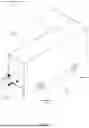
Turning to FIG. 1, a perspective view of a variable displacement pump (100) is shown according to illustrative embodiments. The pump includes a housing (110) mounted on a base (112). The housing (110) encloses internal components, such as an adjustable spline, motor assemblies, and drive mechanisms for actuating a plunger. A pump head (116) extends from a forward face of the housing (110) and is operatively connected to the internal plunger to receive reciprocating displacement for fluid actuation.
The base (112) supports the housing (110) and facilitates installation to external equipment or mounting platforms. A set of securing knobs (114) are positioned along the lateral sides of the base (112). These knobs (114) may be used to clamp or lock the housing (110) in position relative to an external support structure or to permit access for service or configuration. The pump head (116) includes connections for fluid input and output and interfaces with internal check valves and a plunger assembly.
FIG. 2 shows a perspective view of the variable displacement pump (100) with the housing removed to expose internal subassemblies. The pump is mounted to a base (112) and includes a pump motor subassembly (210), a spline adjustment subassembly (225), and a pump head subassembly (220). These subassemblies are operatively aligned along a common longitudinal axis to support reciprocal motion from the motor through the spline to the plunger housed within the pump head.
The pump motor subassembly (210) includes a pump motor (315), and a control unit (218) mounted above the motor. The motor is fixed to a vertical mounting plate secured to the base (112). A shaft extending from the pump motor transmits rotational motion into the adjustable spline (215), which spans the distance between the motor and the pump head subassembly (220). The control unit (218) may house electronic circuitry for managing drive signals, feedback from sensors, and control parameters related to stroke length and motor actuation. In some embodiments, the control unit (218) is a computing system, such as computing system (900), described in FIG. 9 below.
The spline adjustment subassembly (225) is positioned between the pump motor and the pump head. This subassembly includes an adjustment mechanism for modifying the relative axial position of components within the spline, enabling variable displacement control. A circular adjustment feature is shown concentrically mounted around the spline, which may be rotated to translate a threaded interface within the stroke adjustment piston. The adjustment mechanism is operatively connected to the control unit to enable closed-loop adjustment based on input parameters or sensor feedback.
The pump head subassembly (220) receives axial displacement from the adjustable spline (215). Internal to the pump head is a plunger (not visible in this figure) that reciprocates in response to motion transmitted through the spline. The pump head includes valves and fluid flow paths for suction and discharge during operation. The configuration of subassemblies along the base (112) indicates a direct mechanical linkage between the motor, adjustable spline, and plunger.
FIG. 3 shows a front planar view of the variable displacement pump highlighting the pump motor subassembly (210). The subassembly includes a pump motor (315) mounted to a vertically oriented mounting bracket (310), which is secured to the base (112). A control unit (218) is mounted above the pump motor (315) and is positioned to manage motor operation and interface with sensors or control inputs.
A crank (320) is mounted to the output shaft of the pump motor (315). Rotation of the crank (320) causes a crank arm (325) to oscillate. The crank arm (325) is connected at one end to the crank (320) and at the opposite end to a crosshead rod (330). As the crank rotates, the crank arm (325) moves in a circular path, generating reciprocating linear motion in the crosshead rod (330). The geometry shown in this view indicates a crank-slider mechanism that converts rotational motion of the motor to reciprocating motion aligned with the axis of the plunger and adjustable spline.
The mounting bracket (310) provides structural support and alignment for the crank (320) and associated linkage. The crosshead rod (330) is positioned horizontally and extends toward the spline adjustment subassembly, which is not visible in this view. The crosshead rod (330) may include or be coupled to a linear guide or bearing assembly that constrains the motion path and ensures axial displacement is transferred efficiently to the adjustable spline and plunger. The base (112) supports the full mechanical structure and provides a reference for positioning the crank and motor relative to the longitudinal axis of the pump.
FIG. 4A presents a front planar view of the adjustable spline (215). The spline includes a stroke adjustment piston (410) coupled at its rear end to a crank connect (415), which receives reciprocal actuation from the crank mechanism shown in earlier figures. A plunger (420) extends forward from the stroke adjustment piston (410) and terminates in a shaft collar (425). An extension detector (430) is mounted adjacent to the shaft collar (425) and is configured to provide positional feedback corresponding to the axial location of the plunger (420) relative to the stroke adjustment piston. This arrangement enables monitoring of plunger extension for control or safety purposes.
FIG. 4B and FIG. 4C illustrate cross-sectional views of the stroke adjustment piston (410) and the sliding interaction between its internal components. The piston (410) includes a cylinder (412) threadably engaged with a rod (414). A head (422) is formed at the forward end of the cylinder (412), and a stop (416) is fixed at the rear end. The plunger (420) is retained between the stop (416) and the head (422), and is free to slide axially within this constrained volume. The axial distance between the stop (416) and the head (422) defines a stroke offset (435). This stroke offset (435) is fixed by the position of the rod (414) relative to the cylinder (412) and defines a non-driven segment of plunger travel.
In FIG. 4B, the spline is shown moving rearward. The plunger (420) engages the stop (416) and is driven in unison with the stroke adjustment piston (410). In this condition, the stroke of the spline directly produces fluid displacement at the pump head. In FIG. 4C, the spline moves forward, and the plunger (420) slides within the stroke adjustment piston (410) until it contacts the head (422). During this initial segment of motion, defined by the stroke offset (435), the plunger does not contribute to fluid displacement. The result is a reduction in the effective stroke length of the plunger relative to the total mechanical displacement of the spline. This lost motion shortens the pumping stroke and enables modulation of displacement volume without altering the external reciprocating motion.
FIG. 5 illustrates a cross-sectional side view of the adjustment motor subassembly (225). A stepper motor (510) is mounted to a vertical mounting bracket (520) and includes a motor wheel (515) affixed to its output shaft. Although not depicted in the figure, the motor wheel (515) is operatively connected to an adjustment wheel (530) by a mechanical drive element, such as a belt, chain, or gear. The adjustment wheel (530) is concentrically mounted and configured to rotate the cylinder (412) of the stroke adjustment piston (410).
The stroke adjustment piston (410) is positioned within the spline shaft (535) and bearing housing (525). The cylinder (412) of the stroke adjustment piston is threaded along its interior surface and threadably engages a rod (not shown in this figure, but previously identified in FIG. 4). Rotation of the adjustment wheel (530) causes the cylinder (412) to rotate within the spline shaft (535). Because the rod is stationary and threaded, this rotation drives axial translation of the cylinder (412) relative to the rod, thereby modifying the stroke offset (435) described in earlier figures.
The spline shaft (535) surrounds and supports the stroke adjustment piston (410) and is guided within the bearing housing (525). A set of bearings (510) is positioned within the bearing housing (525) to maintain alignment and reduce friction during axial reciprocation of the spline shaft. The axial motion of the spline shaft is derived from the crank mechanism described in prior figures and is independent of the rotational actuation of the adjustment motor subassembly.
A shaft collar (540) is fixed around the spline shaft (535) near the forward interface with the plunger. The shaft collar may function as a mechanical reference or as part of a sensing assembly, such as for detecting extension position. As the cylinder (412) is rotated by the adjustment wheel (530), the axial position of the stop surface within the stroke adjustment piston shifts, which alters the permissible sliding range of the plunger within the piston and thereby adjusts the effective stroke length.
FIG. 6 shows a side cross-sectional view of the pump head subassembly (220), which interfaces with the plunger to produce controlled fluid displacement. The subassembly includes a pump housing (610) containing a cylinder (620) aligned along the axis of the plunger. A plunger connect (615) is threaded into the rear of the pump housing (610) and provides a mechanical coupling for the distal end of the plunger. As the plunger reciprocates, it extends into and retracts from the cylinder (620), displacing fluid within the chamber defined by the interior of the cylinder.
The volume of fluid displaced during each pump cycle depends on the effective stroke length of the plunger, which is determined by the stroke offset established within the stroke adjustment piston. As shown in FIGS. 4B and 4C, the stroke offset creates a portion of plunger motion that does not result in forward travel into the pump head. This lost motion shortens the range over which the plunger actively displaces fluid, thereby modulating the displacement volume without changing the overall reciprocating stroke of the drive mechanism.
The fluid path through the pump head is defined by a pair of check valves (625) installed in the inlet and outlet ports of the pump housing (610). During rearward plunger motion, suction created within the cylinder (620) opens the inlet check valve and admits fluid into the chamber. On the forward stroke, the plunger compresses the fluid, closing the inlet valve and opening the outlet valve to allow discharge. The total volume displaced during this forward motion is reduced proportionally to the stroke offset, which limits the forward extension of the plunger into the cylinder.
A pressure control valve (630) is coupled to a port in the pump housing (610) and communicates with the interior of the cylinder (620). This valve may be used to limit system pressure, enable manual priming, or facilitate relief functions. The location of the pressure control valve below the main axis of fluid flow provides a bleed point for trapped air or excess fluid. The combination of stroke-controlled displacement and one-way valve regulation enables precise control of injection rate based on adjustable mechanical parameters upstream of the pump head.
FIG. 7 shows a side elevation view of the variable displacement pump (100), including mechanical and control components. A pump head subassembly (220) is mounted to the front of the assembly and is aligned axially with a plunger (420), which reciprocates within the pump head to displace fluid. The plunger is driven by a crank-based mechanism on the right side of the figure and passes through an adjustable spline assembly, which modulates stroke length as described in prior figures.
A proximity sensor (710) is mounted to the base (112) below the axial path of the plunger (420). The proximity sensor (710) is configured as an inductive sensor and is positioned to detect an extension detector (430) mounted to or integrated with the plunger. As the plunger reciprocates, the extension detector (430) moves past the proximity sensor (710). The sensor generates a signal when the plunger reaches or exceeds a predefined forward travel limit.
The output of the proximity sensor (710) is operatively connected to the control unit (218), located at the rear of the assembly. The control unit (218), which may include a programmable logic controller, microcontroller, or computer interface, receives positional feedback from the sensor. Based on this feedback, the control unit determines whether the plunger has exceeded its allowable extension into the pump head subassembly (220).
If the plunger travels beyond a programmed threshold, the control unit can trigger a corrective action. This may include halting pump operation, retracting the plunger, or adjusting the stroke offset via the stepper motor of the adjustment motor subassembly. The arrangement enables closed-loop protection against over-insertion, which may otherwise result in mechanical damage or impaired fluid handling. The proximity sensor and extension detector thus provide safety and control functionality integrated with stroke modulation features of the system.
While FIGS. 1-7 show a configuration of components, other configurations may be used without departing from the scope of one or more embodiments. For example, various components may be combined to create a single component. As another example, the functionality performed by a single component may be performed by two or more components.
FIG. 8 illustrates a flowchart representing a method for pumping a fluid using a reciprocating pump with adjustable stroke length, consistent with claims 16-20. In step (810), the method includes providing a reciprocating pump comprising a plunger and a pump head. The plunger is mechanically driven to reciprocate within a pump cylinder formed in the pump head, enabling suction and discharge strokes. In one implementation, the plunger is mechanically linked to a crank-driven adjustable spline configured to translate rotary motion from a motor into reciprocating motion, and the pump head includes check valves to control one-way flow of fluid during pump cycling.
In step (820), the reciprocating pump is operatively connected to a source of fluid. The connection may be made using a suction conduit linked to an inlet port of the pump head. During rearward travel of the plunger, fluid is drawn into the pump chamber through an inlet check valve. On the subsequent forward stroke, the plunger pressurizes the fluid, forcing it through an outlet check valve. This configuration establishes a fluid path from the external source to the discharge location through the internal volume of the pump head.
Step (830) includes adjustably modifying a stroke length of the plunger. In one embodiment, the reciprocating pump includes an adjustable spline formed by a stroke adjustment piston having a cylinder and a threaded rod. The cylinder is rotated relative to the stationary threaded rod to change the axial location of a stop surface internal to the piston. This axial offset defines a stroke offset between the stop and the head of the piston, within which the plunger is free to slide. During operation, this offset results in a portion of each pump cycle where the plunger is not displacing fluid, thus reducing the effective stroke. The stroke offset is adjusted to control displacement volume without modifying the amplitude of the external drive mechanism.
In step (840), the method includes managing displacement of the fluid in the pump head based on the stroke length that was modified. The system includes a stepper motor operatively connected to an adjustment wheel mounted around the cylinder of the stroke adjustment piston. A control unit issues drive signals to the stepper motor to rotate the cylinder and modify the stroke offset. As the stroke offset changes, the plunger's contribution to fluid displacement varies accordingly. The control unit may further manage operational parameters such as stroke frequency and system pressure, and may be responsive to sensor feedback including signals from a proximity sensor associated with an extension detector mounted on the plunger. This feedback enables closed-loop management of plunger motion to avoid overextension and to ensure displacement volume remains within target operating parameters.
While the various steps in this flowchart are presented and described sequentially, at least some of the steps may be executed in different orders, may be combined, or omitted, and at least some of the steps may be executed in parallel. Furthermore, the steps may be performed actively or passively.
Embodiments may be implemented on a computing system specifically designed to achieve an improved technological result. When implemented in a computing system, the features and elements of the disclosure provide a significant technological advancement over computing systems that do not implement the features and elements of the disclosure. Any combination of mobile, desktop, server, router, switch, embedded device, or other types of hardware may be improved by including the features and elements described in the disclosure. For example, as shown in FIG. 9A, the computing system (900) may include one or more computer processors (902), non-persistent storage (904), persistent storage (906), a communication interface (912) (e.g., Bluetooth interface, infrared interface, network interface, optical interface, etc.), and numerous other elements and functionalities that implement the features and elements of the disclosure. The computer processor(s) (902) may be an integrated circuit for processing instructions. The computer processor(s) may be one or more cores or micro-cores of a processor. The computer processor(s) (902) includes one or more processors. The one or more processors may include a central processing unit (CPU), a graphics processing unit (GPU), a tensor processing units (TPU), combinations thereof, etc.
The input devices (910) may include a touchscreen, keyboard, mouse, microphone, touchpad, electronic pen, or any other type of input device. The input devices (910) may receive inputs from a user that are responsive to data and messages presented by the output devices (908). The inputs may include text input, audio input, video input, etc., which may be processed and transmitted by the computing system (900) in accordance with the disclosure. The communication interface (912) may include an integrated circuit for connecting the computing system (900) to a network (not shown) (e.g., a local area network (LAN), a wide area network (WAN) such as the Internet, mobile network, or any other type of network) and/or to another device, such as another computing device.
Further, the output devices (908) may include a display device, a printer, external storage, or any other output device. One or more of the output devices may be the same or different from the input device(s). The input and output device(s) may be locally or remotely connected to the computer processor(s) (902). Many different types of computing systems exist, and the aforementioned input and output device(s) may take other forms. The output devices (908) may display data and messages that are transmitted and received by the computing system (900). The data and messages may include text, audio, video, etc., and include the data and messages described above in the other figures of the disclosure.
Software instructions in the form of computer readable program code to perform embodiments may be stored, in whole or in part, temporarily or permanently, on a non-transitory computer readable medium such as a CD, DVD, storage device, a diskette, a tape, flash memory, physical memory, or any other computer readable storage medium. Specifically, the software instructions may correspond to computer readable program code that, when executed by a processor(s), is configured to perform one or more embodiments of the invention, which may include transmitting, receiving, presenting, and displaying data and messages described in the other figures of the disclosure.
The computing system (900) in FIG. 9A may be connected to or be a part of a network. For example, as shown in FIG. 9B, the network (920) may include multiple nodes (e.g., node X (922), node Y (924)). Each node may correspond to a computing system, such as the computing system shown in FIG. 9A, or a group of nodes combined may correspond to the computing system shown in FIG. 9A. By way of an example, embodiments may be implemented on a node of a distributed system that is connected to other nodes. By way of another example, embodiments may be implemented on a distributed computing system having multiple nodes, where each portion may be located on a different node within the distributed computing system. Further, one or more elements of the aforementioned computing system (900) may be located at a remote location and connected to the other elements over a network.
The nodes (e.g., node X (922), node Y (924)) in the network (920) may be configured to provide services for a client device (926), including receiving requests and transmitting responses to the client device (926). For example, the nodes may be part of a cloud computing system. The client device (926) may be a computing system, such as the computing system shown in FIG. 9A. Further, the client device (926) may include and/or perform all or a portion of one or more embodiments of the invention.
The computing system of FIG. 9A may include functionality to present raw and/or processed data, such as results of comparisons and other processing. For example, presenting data may be accomplished through various presenting methods. Specifically, data may be presented by being displayed in a user interface, transmitted to a different computing system, and stored. The user interface may include a GUI that displays information on a display device. The GUI may include various GUI widgets that organize what data is shown as well as how data is presented to a user. Furthermore, the GUI may present data directly to the user, e.g., data presented as actual data values through text, or rendered by the computing device into a visual representation of the data, such as through visualizing a data model.
The various descriptions of the figures may be combined and may include or be included within the features described in the other figures of the application. The various elements, systems, components, and steps shown in the figures may be omitted, repeated, combined, or altered as shown in the figures. Accordingly, the scope of the present disclosure should not be considered limited to the specific arrangements shown in the figures.
The term “about,” when used with respect to a physical property that may be measured, refers to an engineering tolerance anticipated or determined by an engineer or manufacturing technician of ordinary skill in the art. The exact quantified degree of an engineering tolerance depends on the product being produced and the technical property being measured. For example, two angles may be “about congruent” if the values of the two angles are within a first predetermined range of angles for one embodiment, but also may be “about congruent” if the values of the two angles are within a second predetermined range of angles for another embodiment. The ordinary artisan is capable of assessing what is an acceptable engineering tolerance for a particular product, and thus is capable of assessing how to determine the variance of measurement contemplated by the term “about.”
As used herein, the term “connected to” contemplates at least two meanings, unless stated otherwise. In a first meaning, “connected to” means that component A was, at least at some point, separate from component B, but then was later joined to component B in either a fixed or a removably attached arrangement. In a second meaning, “connected to” means that component A could have been integrally formed with component B. Thus, for example, a bottom of a pan is “connected to” a wall of the pan. The term “connected to” may be interpreted as the bottom and the wall being separate components that are snapped together, welded, or are otherwise fixedly or removably attached to each other. However, the bottom and the wall may be deemed “connected” when formed contiguously together as a monocoque body.
In the application, ordinal numbers (e.g., first, second, third, etc.) may be used as an adjective for an element (i.e., any noun in the application). The use of ordinal numbers is not to imply or create any particular ordering of the elements nor to limit any element to being only a single element unless expressly disclosed, such as by the use of the terms “before”, “after”, “single”, and other such terminology. Rather, ordinal numbers distinguish between the elements. By way of an example, a first element is distinct from a second element, and the first element may encompass more than one element and succeed (or precede) the second element in an ordering of elements.
Further, unless expressly stated otherwise, the conjunction “or” is an inclusive “or” and, as such, automatically includes the conjunction “and” unless expressly stated otherwise. Further, items joined by the conjunction “or” may include any combination of the items with any number of each item, unless expressly stated otherwise.
In the above description, numerous specific details are set forth in order to provide a more thorough understanding of the disclosure. However, it will be apparent to one of ordinary skill in the art that the technology may be practiced without these specific details. In other instances, well-known features have not been described in detail to avoid unnecessarily complicating the description. Further, other embodiments not explicitly described above can be devised which do not depart from the scope of the claims as disclosed herein. Accordingly, the scope should be limited only by the attached claims.
Claims
What is claimed is:1. A variable displacement pump comprising:
a pump motor;
an adjustable spline, operatively connected to the pump motor at a first end of the adjustable spline;
a plunger, connected to a second end of the adjustable spline; and
a pump head, operatively connected to the plunger;
wherein the adjustable spline is configured to adjustably modify a stroke length of the plunger.
2. The variable displacement pump of claim 1, where in the adjustable spline further comprises:
a stroke adjustment piston comprising:
a cylinder; and
a rod, adjustably coupled to a first end of the cylinder;
wherein the plunger is slidably coupled to a second end of a cylinder;
wherein the stroke adjustment piston is configured to adjustably modify a
stroke offset within the stroke adjustment piston.
3. The variable displacement pump of claim 2, wherein the rod is threaded and coupled to corresponding threads along an interior of the cylinder, and wherein the variable displacement pump further comprising:
an adjustment wheel, mounted around the cylinder of the stroke adjustment piston and co-rotatable with the cylinder;
wherein the adjustment wheel is configured to rotate with the cylinder to modify the stroke offset.
4. The variable displacement pump of claim 3, further comprising:
a stepper motor, operatively connected to the adjustment wheel.
5. The variable displacement pump of claim 4, wherein the operable connection between the stepper motor and the adjustment wheel is selected from the group consisting of a belt drive, a chain drive, a gear drive, and a screw drive.
6. The variable displacement pump of claim 1, further comprising:
a control unit configured to manage parameters for operation of the variable displacement pump, wherein the parameters include the stroke length.
7. The variable displacement pump of claim 6, further comprising:
a stepper motor, operatively connected to the adjustable spline;
wherein the control unit is configured to manage operation of the stepper motor to adjustably modify a stroke length of the plunger.
8. The variable displacement pump of claim 6, further comprising:
an extension detector associated with the plunger; and
a proximity sensor mounted to a base of the variable displacement pump and operatively connected to the control unit;
wherein the proximity sensor is configured to detect a proximity of the extension detector;
wherein the control unit is configured to determine an extension of the adjustable spline based on feedback from the proximity sensor.
9. The variable displacement pump of claim 8, wherein determining the extension prevents over insertion of the plunger into the pump head.
10. An adjustable spline for a reciprocating pump, the adjustable spline comprising:
a stroke adjustment piston comprising:
a cylinder;
a rod, adjustably coupled to a first end of the cylinder; and
a stop associated with a second end of the cylinder;
wherein the adjustable spline is configured to be operatively connected to a pump motor at a first end of the adjustable spline, and to be connected to a plunger at the second end of the adjustable spline.
11. The adjustable spline of claim 10, wherein the cylinder is configured to slidably restrain a head of the plunger between the stop and the rod.
12. The adjustable spline of claim 10, wherein the rod is threaded and coupled to corresponding threads along an interior of the cylinder.
13. The adjustable spline of claim 10, further comprising:
an adjustment wheel, mounted around the cylinder of the stroke adjustment piston and co-rotatable with the cylinder;
wherein the adjustment wheel is configured to rotate with the cylinder to modify a stroke offset within the stroke adjustment piston.
14. The adjustable spline of claim 13, wherein the adjustment wheel is configured to be operatively connected to a stepper motor.
15. The adjustable spline of claim 14, wherein the operable connection between the stepper motor and the adjustment wheel is selected from the group consisting of a belt drive, a chain drive, a gear drive, and a screw drive.
16. A method for pumping a fluid, the method comprising:
providing a reciprocating pump, wherein the reciprocating pump comprises a plunger and a pump head;
operatively connecting the reciprocating pump to a source of fluid; and
adjustably modifying a stroke length of a plunger of the reciprocating pump;
managing displacement of the fluid in the pump head based on the stroke length that was modified.
17. The method of claim 16, wherein the reciprocating pump further comprises:
an adjustable spline, operatively connected to the pump motor at a first end of the adjustable spline, and connected to the plunger at a second end of the adjustable spline; and
a pump head, operatively connected to the plunger;
wherein modifying the stroke length is performed in part by the adjustable
spline.
18. The method of claim 17, wherein the adjustable spline further comprises:
a stroke adjustment piston comprising:
a cylinder; and
a rod, adjustably coupled to a first end of the cylinder;
wherein the method further comprises:
slidably coupling the plunger to a second end of a cylinder; and
adjustably modifying a stroke offset within the stroke adjustment piston.
19. The method of claim 17, wherein the reciprocating pump further comprises:
a stepper motor, operatively connected to the adjustable spline; and
a control unit;
wherein the method further comprises:
managing parameters for operation of the variable displacement pump, wherein the parameters include the stroke length; and
managing operation of the stepper motor to adjustably modify the stroke length of the plunger.
20. The method of claim 18, wherein the rod is threaded and coupled to corresponding threads along an interior of the cylinder, and wherein the variable displacement pump further comprising:
an adjustment wheel operatively connected to the stepper motor, wherein the adjustment wheel is mounted around the cylinder of the stroke adjustment piston and co-rotatable with the cylinder;
wherein the method further comprises:
driving the adjustment wheel with the stepper motor to rotate the cylinder; and
modifying the stroke offset within the stroke adjustment piston based on the rotation of the cylinder.
Images & Drawings included:


Sources:
- United States Patent and Trademark Office - verify current appl. status at the USPTO↗
Similar patent applications:
- » 20090101092
Variable displacement pump, valve timing control device using the variable displacement pump, and valve timing control system using the variable displacement pump, for use in internal combustion engines - » 20150050165
Control unit for hydraulic variable displacement pumps and variable displacement pump with a control unit - » 20100205952
Variable displacement pump and power steering apparatus using the variable displacement pump - » 20110194967
VARIABLE DISPLACEMENT PUMP, OIL JET AND LUBLICATING SYSTEM USING VARIABLE DISPLACEMENT PUMP - » 20260055762
VARIABLE DISPLACEMENT OIL PUMP AND METHOD FOR PRODUCING VARIABLE DISPLACEMENT OIL PUMP - » 10202131
Control device for a proportionally adjustable hydraulic pump and a variable displacement pump for a hydrostatic drive - » 20060198736
Pump control system for variable displacement pump - » 10359279
Variable displacement pump - » 10317210
Sensor for a variable displacement pump - » 10432615
Variable displacement pump
Recent applications in this class:
- » 20260078751 2026-03-19
GAS COMPRESSOR AND SYSTEM AND METHOD FOR GAS COMPRESSING - » 20250334112 2025-10-30
CALIBRATABLE VARIABLE DISPLACEMENT PUMP - » 20250314247 2025-10-09
CALIBRATABLE VARIABLE DISPLACEMENT PUMP - » 20250223958 2025-07-10
APPARATUSES, SYSTEMS, AND METHODS FOR ADJUSTING THE EFFECTIVE STROKE-LENGTH OF A POSITIVE DISPLACEMENT PUMP - » 20240418161 2024-12-19
GAS COMPRESSOR AND SYSTEM AND METHOD FOR GAS COMPRESSING - » 20240410358 2024-12-12
DIRECT CONTROLLED VARIABLE DISPLACEMENT PUMP FUEL SYSTEMS WITH LOW PRESSURE THERMAL RECIRCULATION PUMPING - » 20240352928 2024-10-24
Metering positive displacement pump stroke length limiter - » 20230383742 2023-11-30
PUMP COMPRISING COOLING MEANS - » 20230366393 2023-11-16
Bent axis plunger-type variable hydraulic motor pump - » 20230130997 2023-04-27
Variable displacement pumps