ELECTRIC COMPRESSOR
US20260146607A1
2026-05-28
19/389,447
2025-11-14
Smart Summary: An electric compressor is a device that compresses fluids using electricity. It has a special case that holds both the compression parts and an electric motor. The motor has two main parts: a stator and a rotor, which work together to create movement. An inverter, which helps control the electric motor, is attached to the outside of the case. Inside the case, there is a support that holds the stator in place, and this support is separate from a wall that keeps the inside of the case separate from the outside. 🚀 TL;DR
Abstract:
An electric compressor includes a housing, a compression mechanism configured to compress a fluid, an electric motor, and an inverter. The housing has an accommodation chamber in which the compression mechanism and the electric motor are accommodated. The electric motor has a stator and a rotor that is driven rotatably by the stator. The inverter is fixed to the housing and disposed outside the accommodation chamber. The housing has a partition that separates the accommodation chamber from an outside of the accommodation chamber and a support that is located in the accommodation chamber and supports the stator. The support is provided separately from the partition and is supported by the partition.
Inventors:
- Yuji Hashimoto 15 🇯🇵 Kariya-shi, Japan
- Kazunari HONDA 42 🇯🇵 Kariya-shi, Japan
- Hiroyuki KOBAYASHI 11 🇯🇵 Kariya-shi, Japan
- Akito SUGAHARA 5 🇯🇵 Kariya-shi, Japan
- Keishiro MUTO 4 🇯🇵 Kariya-shi, Japan
Assignee:
- KABUSHIKI KAISHA TOYOTA JIDOSHOKKI 1,038 🇯🇵 Kariya-shi, Japan
Applicant:
Interested in similar patents?
Get notified when new applications in this technology area are published.
Classification:
F04C18/023 » CPC main
Rotary-piston pumps specially adapted for elastic fluids of arcuate-engagement type, i.e. with circular translatory movement of co-operating members, each member having the same number of teeth or tooth-equivalents both members having co-operating elements in spiral form where both members are moving
F04C29/0057 » CPC further
Component parts, details or accessories of pumps or pumping installations, not provided for in groups - ; Driving elements, brakes, couplings, transmissions specially adapted for pumps; Means for transmitting movement from the prime mover to driven parts of the pump, e.g. clutches, couplings, transmissions for eccentric movement
F04C2240/30 » CPC further
Components Casings or housings
F04C2240/403 » CPC further
Components; Electric motor with inverter for speed control
F04C18/02 IPC
Rotary-piston pumps specially adapted for elastic fluids of arcuate-engagement type, i.e. with circular translatory movement of co-operating members, each member having the same number of teeth or tooth-equivalents
F04C29/00 IPC
Component parts, details or accessories of pumps or pumping installations, not provided for in groups -
Description
CROSS-REFERENCE OF THE RELATED APPLICATION
This application claims priority to Japanese Patent Application No. 2024-203672 filed on Nov. 22, 2024, the entire disclosure of which is incorporated herein by reference.
BACKGROUND ART
The present disclosure related to an electric compressor.
Japanese Patent Application Publication No. H02-227575 discloses a conventional electric compressor. This electric compressor includes a housing, a compression mechanism, and an electric motor. An accommodation chamber is formed inside the housing. Fluid is sucked into the accommodation chamber from an outside of the housing, and a compression mechanism and an electric motor are accommodated in the accommodation chamber.
A support is formed integrally with the housing therein. The support is located in the accommodation chamber and extends toward the compression mechanism in an axial direction of the electric compressor. A discharge passage is formed in the support. The discharge passage communicates with the outside of the housing.
The compression mechanism has a driving scroll and a driven scroll. The driving scroll and the driven scroll form a compression chamber in which the fluid is compressed. The compression chamber communicates with the discharge passage. The driving scroll has a cover body. The driving scroll is rotatably supported by the support through the cover body.
The electric motor has a stator and a rotor. The stator is fixed to the housing. The rotor is disposed inside the stator and is driven rotatably by the stator. The rotor is fixed to the cover body.
In this electric compressor, the electric motor is driven rotatably to operate the compression mechanism. As a result, the compression mechanism is configured to compress the fluid in the compression chamber. The fluid compressed in the compression chamber is discharged to the outside of the housing through the discharge passage.
In this type of electric compressor, an inverter configured to control operation of the electric motor is provided. The inverter is typically fixed to the housing and is located outside the accommodation chamber.
Here, in the conventional electric compressor described above, the support is formed integrally with the housing, and the rotor is fixed to the cover body supported by this support. Accordingly, heat generated in the rotor, which reaches a high temperature during its operation, is transferred to the support through the cover body, and then, is transferred from the support to the housing. In addition, heat generated in the stator, which is fixed to the housing, is also transferred to the housing. As a result, in this electric compressor, a temperature of the housing is likely to become higher during an operation of the electric compressor. For this reason, in this electric compressor, when the inverter is fixed to the housing, since the inverter is likely to be affected by the heat of the housing at the high temperature, the inverter is likely to be damaged.
This leads to an idea that parts superior in heat resistance are used in the inverter; however, in this idea, a manufacturing cost of the inverter, and by extension, the electric compressor is increased.
The present disclosure has been made in view of the above-mentioned conventional circumstances, and is directed to providing an electric compressor that is capable of suitably preventing damage to an inverter by heat and reducing a manufacturing cost of the electric compressor.
SUMMARY
In accordance with an aspect of the present disclosure, there is provided an electric compressor that includes a housing, a compression mechanism configured to compress a fluid, an electric motor configured to operate the compression mechanism, and an inverter configured to control operation of the electric motor. The housing has an accommodation chamber into which the fluid is sucked from an outside of the housing and in which the compression mechanism and the electric motor are accommodated. The electric motor has a stator and a rotor that surrounds the stator and is driven rotatably by the stator. The inverter is fixed to the housing and disposed outside the accommodation chamber. The housing has a partition that separates the accommodation chamber from an outside of the accommodation chamber and a support that is located in the accommodation chamber and supports the stator. The support is provided separately from the partition and is supported by the partition.
Other aspects and advantages of the disclosure will become apparent from the following description, taken in conjunction with the accompanying drawings, illustrating by way of example the principles of the disclosure.
BRIEF DESCRIPTION OF THE DRAWINGS
The disclosure, together with objects and advantages thereof, may best be understood by reference to the following description of the embodiments together with the accompanying drawings in which:
FIG. 1 is a cross-sectional view of an electric compressor according to a first embodiment; and
FIG. 2 is a cross-sectional view of an electric compressor according to a second embodiment.
DETAILED DESCRIPTION OF THE EMBODIMENTS
The following will describe a first embodiment and a second embodiment according to the present disclosure with reference to the accompanying drawings. An electric compressor of each of the first embodiment and the second embodiment is mounted on a vehicle, which is not illustrated, and is a part of an air conditioner of the vehicle.
First Embodiment
As illustrated in FIG. 1, the electric compressor of the first embodiment includes a housing 6, an electric motor 10, a compression mechanism 2, and an inverter 3.
In the present embodiment, a front-rear direction of the electric compressor is defined by an arrow in FIG. 1. Similarly to the electric compressor in the second embodiment, a front-rear direction is defined by an arrow in FIG. 2. These front-rear directions are examples of the “axial direction” in the present disclosure. Note that these front-rear directions are examples for convenience of explanation, and a posture of the electric compressor may be changed as appropriate depending on the vehicle on which the electric compressor is mounted.
As illustrated in FIG. 1, the housing 6 includes a housing main body 60, a support 64, a partition 61, and an inverter cover 62.
The housing main body 60 is made of aluminum alloy. The housing main body 60 has a first outer peripheral wall 60a and a first bottom wall 60b. The first outer peripheral wall 60a is an example of the “peripheral wall” in the present disclosure, and the first bottom wall 60b is an example of the “bottom wall” in the present disclosure. The first outer peripheral wall 60a is formed in a cylindrical shape centered about a driving axis O1. The driving axis O1 is parallel to the front-rear direction.
A suction communication port 71 is formed in the first outer peripheral wall 60a. The suction communication port 71 extends in a radial direction of the housing main body 60. The suction communication port 71 is connected to an evaporator through a pipe. Here, illustrations of the evaporator and the pipe are omitted.
The first bottom wall 60b is located at a front end of the housing main body 60. The first bottom wall 60b is formed in a substantially circular plate shape extending perpendicularly to the driving axis O1. An outer peripheral edge of the first bottom wall 60b is connected to a front end of the first outer peripheral wall 60a. These first outer peripheral wall 60a and first bottom wall 60b form the housing main body 60 having a bottomed tubular shape with its rear end open.
The first bottom wall 60b has a front surface 601 that is oriented forward and a rear surface 602 that is located opposite to the front surface 601 and is oriented rearward. A first supporting portion 66 and a discharge communication port 72 are formed in the first bottom wall 60b. The first supporting portion 66 is formed integrally with the first bottom wall 60b substantially at the center of the rear surface 602 and protrudes rearward from the rear surface 602. The first supporting portion 66 is formed in a cylindrical shape centered about the driving axis O1 and has a radial ball bearing 52 and a shaft sealing member 63 therein. Note that the first supporting portion 66 may have a plain bearing therein, instead of the radial ball bearing 52.
The shaft sealing member 63 is located in front of the radial ball bearing 52 inside the first supporting portion 66. The shaft sealing member 63 has an annular shape.
The discharge communication port 72 extends through the first bottom wall 60b in a direction in which the driving axis O1 extends and communicates with an inside of the first supporting portion 66. The discharge communication port 72 is connected to a condenser through a pipe. Here, illustrations of the condenser and the pipe are omitted.
The partition 61 is made of aluminum alloy. The partition 61 is provided separately from the housing main body 60 and is located behind the housing main body 60. The partition 61 is formed in a substantially disc shape centered about the driving axis O1. The partition 61 is formed so as to have substantially the same diameter as that of the first outer peripheral wall 60a of the housing main body 60.
The partition 61 has a first surface 61a that is oriented forward and a second surface 61b that is located opposite to the first surface 61a and is oriented rearward. The partition 61 has a mounting recess 61c. The mounting recess 61c is formed in a substantially columnar shape that is recessed rearward in the first surface 61a. Here, a diameter of the mounting recess 61c is larger than that of a first diameter portion 64a of the support 64, which will be described later.
A first heat insulation body 91 is provided in the mounting recess 61c. The first heat insulation body 91 is an example of the “heat insulation body” in the present disclosure. The first heat insulation body 91 is made of resin, such as synthetic rubber, having heat insulation property and elasticity. The first heat insulation body 91 is formed in a bottomed tubular shape with its front end open.
The support 64 is provided separately from the housing main body 60 and the partition 61. The support 64 is made of steel. The support 64 has the first diameter portion 64a and a second diameter portion 64b. These first diameter portion 64a and second diameter portion 64b are formed integrally with each other. Note that the support 64 may be made of aluminum alloy.
The first diameter portion 64a is located behind the second diameter portion 64b and corresponds to a rear portion of the support 64. The first diameter portion 64a has therein a second fluid passage 642, which will be described later, so that the first diameter portion 64a has a bottomed tubular shape. A second heat insulation body 92 is provided on the first diameter portion 64a. The second heat insulation body 92 is an example of the “heat insulation member” in the present disclosure. Similarly to the first heat insulation body 91, the second heat insulation body 92 is also made of resin, such as synthetic rubber, having heat insulation property and elasticity. The second heat insulation body 92 is formed in a tubular shape extending in the direction in which the driving axis O1 extends and is attached to an outer peripheral surface of the first diameter portion 64a. Note that the first heat insulation body 91 and the second heat insulation body 92 may be made of different materials.
The second diameter portion 64b is formed in a substantially columnar shape extending from a front end of the first diameter portion 64a forward in the direction in which the driving axis O1 extends. Thus, the second diameter portion 64b corresponds to a front portion of the support 64. A diameter of the second diameter portion 64b is smaller than that of the first diameter portion 64a.
A pin hole 55a is formed in the second diameter portion 64b. The pin hole 55a is opened in a front end surface of the second diameter portion 64b and extends inside the second diameter portion 64b rearward in the direction in which the driving axis O1 extends. Here, the pin hole 55a does not extend through the second diameter portion 64b in the direction in which the driving axis O1 extends. Thus, the pin hole 55a does not communicate with the second fluid passage 642, which will be described later. Note that the pin hole 55a may extend through the second diameter portion 64b in the direction in which the driving axis O1 extends and communicate with the second fluid passage 642.
The support 64 has a fluid passage 64c. The fluid passage 64c includes a first fluid passage 641, the second fluid passage 642, and a third fluid passage 643. The first fluid passage 641 extends through the first diameter portion 64a in a radial direction of the support 64. One end of the first fluid passage 641 is open in the outer peripheral surface of the first diameter portion 64a.
The second fluid passage 642 is formed in the first diameter portion 64a. The second fluid passage 642 is recessed forward in a rear end of the first diameter portion 64a. As a result, the second fluid passage 642 communicates with the other end of the first fluid passage 641.
The third fluid passage 643 is formed in the first diameter portion 64a. The third fluid passage 643 extends through the first diameter portion 64a in the direction in which the driving axis O1 extends. A front end of the third fluid passage 643 is opened in a front end surface of the first diameter portion 64a on an outer peripheral side of the second diameter portion 64b, and a rear end of the third fluid passage 643 communicates with the second fluid passage 642. Thus, the first fluid passage 641 and the third fluid passage 643 communicate with each other through the second fluid passage 642.
A rear portion of the first diameter portion 64a in the support 64 is positioned inside the first heat insulation body 91, and by extension, the mounting recess 61c. Then, in this state, the support 64 is fastened to the partition 61 with bolts, which are not illustrated, inserted from a side of the second surface 61b of the partition 61. Thus, the support 64 is supported by the partition 61 through the first heat insulation body 91. When the support 64 is supported by the partition 61 as described above, a rear end of the second fluid passage 642 in the support 64 is closed by the first heat insulation body 91 and the partition 61.
The inverter cover 62 is made of aluminum alloy. The inverter cover 62 has a second outer peripheral wall 62a and a second bottom wall 62b. The second outer peripheral wall 62a is formed in a cylindrical shape centered about the driving axis O1. The second outer peripheral wall 62a is formed so as to have substantially the same diameter as those of the first outer peripheral wall 60a and the partition 61.
The second bottom wall 62b is located at a rear end of the inverter cover 62. The second bottom wall 62b is formed in a substantially circular plate shape extending perpendicularly to the driving axis O1. An outer peripheral edge of the second bottom wall 62b is connected to a rear end of the second outer peripheral wall 62a. These second outer peripheral wall 62a and second bottom wall 62b form the inverter cover 62 having a bottomed tubular shape with its front end open. Although not illustrated, a connector portion is formed in the inverter cover 62.
In the housing 6, the first surface 61a of the partition 61 is in contact with a rear end of the first outer peripheral wall 60a. In addition, a front end of the second outer peripheral wall 62a is in contact with the second surface 61b of the partition 61. In this state, the housing main body 60, the partition 61, and the inverter cover 62 are fixed to each other in the direction in which the driving axis O1 extends with a plurality of bolts, which are not illustrated, inserted from a side of the inverter cover 62. Thus, the housing main body 60, the partition 61, and the inverter cover 62 are integrated with each other in the housing 6.
In the housing 6, the housing main body 60 is closed by the partition 61 on a rear side of the housing main body 60 to form a scroll chamber 65 in the housing main body 60. The scroll chamber 65 is an example of the “accommodation chamber” in the present disclosure. The scroll chamber 65 communicates with the suction communication port 71. Thus, a refrigerant is sucked into the scroll chamber 65 from an outside of the housing 6 through the suction communication port 71. The refrigerant is an example of the “fluid” in the present disclosure.
In the housing 6, the inverter cover 62 is closed by the partition 61 on a front side of the inverter cover 62 to form an inverter chamber 620 in the inverter cover 62. The inverter chamber 620 is located outside the scroll chamber 65. The inverter chamber 620 and the scroll chamber 65 are separated from each other by the partition 61.
The support 64 is supported by the partition 61 and is located in the scroll chamber 65. The support 64 extends from the partition 61 forward, that is, toward the compression mechanism 2. In the support 64, the first fluid passage 641 of the fluid passage 64c faces the scroll chamber 65. That is, the fluid passage 64c communicates with the scroll chamber 65.
Here, as described above, whereas the support 64 is made of steel, the partition 61 is made of aluminum alloy. Accordingly, thermal conductivity of the support 64 is smaller than that of the partition 61.
The housing 6 includes the housing main body 60, the support 64, the partition 61, and the inverter cover 62. These housing main body 60, partition 61, and inverter cover 62 are made of aluminum alloy, and the support 64 is made of steel. On the other hand, the first heat insulation body 91 and the second heat insulation body 92 are both made of synthetic rubber. Thus, stiffness of the first heat insulation body 91 and the second heat insulation body 92 is lower than that of the housing 6 and the support 64.
The electric motor 10 is accommodated in the scroll chamber 65. The electric motor 10 includes a stator 17 and a rotor 11. The stator 17 has a stator core 17a and a winding 17b. The stator core 17a is formed in a cylindrical shape centered about the driving axis O1. The winding 17b is wound around the stator core 17a. As a result, the winding 17b forms a first coil end 171 and a second coil end 172.
The stator 17 is supported by the outer peripheral surface of the first diameter portion 64a in a state where the second heat insulation body 92 is positioned inside the stator core 17a. Thus, the stator core 17a, and by extension, the stator 17 is supported by the support 64 through the second heat insulation body 92. Note that although not illustrated, a plurality of slits extending in the direction in which the driving axis O1 extends are formed in an inner peripheral surface of the stator core 17a. These slits form gaps between the second heat insulation body 92 and the stator core 17a.
The rotor 11 is formed in a cylindrical shape centered about the driving axis O1. Although a detailed illustration is omitted, the rotor 11 is formed of a plurality of permanent magnets corresponding to the stator 17 and laminated steel plates for fixing the permanent magnets. A diameter of the rotor 11 is larger than that of the stator core 17a. Accordingly, the rotor 11 surrounds the stator core 17a in the scroll chamber 65. A plurality of first bolt holes 11a are formed in the rotor 11. The first bolt holes 11a extend through the rotor 11 in the direction in which the driving axis O1 extends.
The compression mechanism 2 is accommodated in the scroll chamber 65. The compression mechanism 2 has a driving scroll 30, a driven scroll 40, and a driven mechanism 20.
The driving scroll 30 is made of aluminum alloy. The driving scroll 30 has a driving scroll end plate 31, a driving scroll spiral body 33, a driving scroll peripheral wall 35, a first cover body 37, and a first case 39.
The driving scroll end plate 31 is formed in a substantially disc shape extending perpendicularly to the driving axis O1 and a driven axis O2. The driven axis O2 extends in parallel to the driving axis O1 while being eccentric to the driving axis O1. That is, the driven axis O2 is also parallel to the front-rear direction. The driving scroll end plate 31 has a first front surface 311 that is oriented forward and a first rear surface 312 that is located opposite to the first front surface 311 and is oriented rearward.
A discharge port 32 is formed in the driving scroll end plate 31. The discharge port 32 extends through the driving scroll end plate 31 in the direction in which the driving axis O1 extends. A discharge reed valve 57 and a retainer 58 are fixed to the first front surface 311 of the driving scroll end plate 31 with a bolt 59. This allows the discharge reed valve 57 to open and close the discharge port 32. An opening degree of the discharge reed valve 57 is adjustable by the retainer 58.
The driving scroll spiral body 33 is integrated with the driving scroll end plate 31 and protrudes from the first rear surface 312 rearward, that is, toward the driven scroll 40 in parallel to the driving axis O1 and the driven axis O2. Although a detailed illustration is omitted, the driving scroll spiral body 33 has a spiral shape centered about a center of the driving scroll end plate 31 and extending radially outwardly from the center of the spiral shape.
The driving scroll peripheral wall 35 is formed in a cylindrical shape centered about the driving axis O1 and extending in parallel to the driving axis O1 and the driven axis O2. A front end of the driving scroll peripheral wall 35 is integrated with an outer peripheral edge of the driving scroll end plate 31. Accordingly, the driving scroll peripheral wall 35 is formed in a cylindrical shape protruding rearward from the first rear surface 312 while enclosing the driving scroll spiral body 33. Note that although not illustrated, an outer peripheral end of the spiral in the driving scroll spiral body 33 is connected to an inner peripheral surface of the driving scroll peripheral wall 35.
The first cover body 37 has a wall portion 37a, an inner tubular portion 37b, and an outer tubular portion 37c. The wall portion 37a is formed in a substantially disc shape extending in a radial direction of the driving scroll 30. The wall portion 37a has a second front surface 371 that is oriented forward and a second rear surface 372 that is located opposite to the second front surface 371 and is oriented rearward.
A recess 373 and a suction port 374 are formed in the wall portion 37a. The recess 373 is located at a substantially center of the second front surface 371 and recessed rearward in the second front surface 371.
The suction port 374 is located outside the recess 373 in the radial direction of the driving scroll 30. The suction port 374 extends through the wall portion 37a in the direction in which the driving axis O1 extends. A front end of the suction port 374 is open in the second front surface 371, and a rear end of the suction port 374 is open in the second rear surface 372. Here, in this electric compressor, the suction port 374 is formed only in the wall portion 37a. The only one suction port 374 is formed in the wall portion 37a. Note that a plurality of the suction ports 374 may be formed in the wall portion 37a.
A plurality of rings 22 are attached to a portion of the wall portion 37a between the recess 373 and the suction port 374. Although detailed illustrations are omitted, the rings 22 are arranged at regular intervals in a circumferential direction of the recess 373 while being oriented forward and surround the recess 373. Note that the number of the rings 22 is six in the present embodiment. FIG. 1 illustrates one of the six rings 22.
The inner tubular portion 37b is located inside the stator 17 in the radial direction of the driving scroll 30 and is formed in a cylindrical shape protruding from the second rear surface 372 of the wall portion 37a rearward in the direction in which the driving axis O1 extends. An outer diameter of the inner tubular portion 37b is larger than that of the second diameter portion 64b of the support 64 and is smaller than that of the first diameter portion 64a.
An insertion hole 375 is formed in the first cover body 37. The insertion hole 375 has substantially the same diameter as that of the second diameter portion 64b of the support 64 and forms an inner peripheral surface of the inner tubular portion 37b. The insertion hole 375 extends in the direction in which the driving axis O1 extends and communicates with the recess 373.
A first plain bearing 51 is provided in the insertion hole 375. Note that a coating layer or a plating layer that provides slidability may be provided on an inner peripheral surface of the insertion hole 375 or an outer peripheral surface of the second diameter portion 64b in the support 64, instead of the first plain bearing 51. Alternatively, a radial ball bearing may be provided in the insertion hole 375 instead of the first plain bearing 51.
The outer tubular portion 37c is integrated with the wall portion 37a at an outer peripheral edge of the wall portion 37a. Thus, the outer tubular portion 37c is connected to the wall portion 37a and is formed in a cylindrical shape extending from the wall portion 37a rearward in the direction in which the driving axis O1 extends. An outer diameter of the outer tubular portion 37c is substantially the same as those of the driving scroll peripheral wall 35 and the rotor 11.
An inner diameter of the outer tubular portion 37c is larger than the outer diameter of the inner tubular portion 37b. That is, in the first cover body 37, the inner tubular portion 37b is located inside the outer tubular portion 37c while keeping at a distance from the outer tubular portion 37c in the radial direction of the driving scroll 30. Thus, in the first cover body 37, the wall portion 37a, the inner tubular portion 37b, and the outer tubular portion 37c form a coil end accommodation portion 38. The coil end accommodation portion 38 has a bottomed annular shape with its rear end open.
The suction port 374 is located at a portion of the wall portion 37a between the inner tubular portion 37b and the outer tubular portion 37c in the radial direction of the driving scroll 30. Thus, the suction port 374 communicates with the coil end accommodation portion 38 at the portion between the inner tubular portion 37b and the outer tubular portion 37c.
A plurality of second bolt holes 376 are formed in the first cover body 37. The second bolt holes 376 extend through the wall portion 37a in the direction in which the driving axis O1 extends. Although not illustrated, the number of the second bolt holes 376 is equal to the number of the first bolt holes 11a formed in the rotor 11. FIG. 1 illustrates one of the plurality of the first bolt holes 11a and one of the plurality of the second bolt holes 376.
A front end of the outer tubular portion 37c in the first cover body 37 is in contact with a rear end of the driving scroll peripheral wall 35. A rear end of the outer tubular portion 37c in the first cover body 37 is in contact with the rotor 11. In this state, the first bolts 34a are inserted into the first bolt holes 11a and the second bolt holes 376 in this order from a side of the rotor 11 and are screwed to the driving scroll peripheral wall 35. Thus, the first cover body 37 is held between the driving scroll peripheral wall 35 and the rotor 11 in the front-rear direction and is fixed to the driving scroll peripheral wall 35 and the rotor 11. As a result, the driving scroll 30 is integrated with the rotor 11.
The first case 39 has an outer peripheral wall 39a and a front wall 39b. The outer peripheral wall 39a is formed in a cylindrical shape centered about the driving axis O1. Here, an outer diameter of the outer peripheral wall 39a is substantially the same as that of the driving scroll peripheral wall 35.
The front wall 39b is located at a front end of the first case 39. The front wall 39b is formed in a substantially disc shape extending perpendicularly to the driving axis O1 and the driven axis O2. An outer peripheral edge of the front wall 39b is connected to a front end of the outer peripheral wall 39a. These outer peripheral wall 39a and front wall 39b form the first case 39 having a bottomed tubular shape with its rear end open.
A first boss 39c is formed in the front wall 39b. The first boss 39c is integrated with the front wall 39b at a center thereof and protrudes from the front wall 39b forward in the direction in which the driving axis O1 extends. An outer diameter of the first boss 39c is substantially the same as an inner diameter of the radial ball bearing 52 and an inner diameter of the shaft sealing member 63. A discharge passage 390 is formed in the first boss 39c. The discharge passage 390 extends through the first boss 39c in the direction in which the driving axis O1 extends.
A plurality of third bolt holes 39d are formed in the first case 39. The third bolt holes 39d extend through the outer peripheral wall 39a and the front wall 39b in the direction in which the driving axis O1 extends. Although not illustrated, the plurality of the third bolt holes 39d are formed in the outer peripheral wall 39a and the front wall 39b. FIG. 1 illustrates one of the plurality of the third bolt holes 39d.
A rear end of the outer peripheral wall 39a in the first case 39 is in contact with the front end of the driving scroll peripheral wall 35. In this state, second bolts 34b are each inserted into a corresponding one of the third bolt holes 39d and are screwed to the driving scroll peripheral wall 35. Thus, in the driving scroll 30, the first case 39 is fixed to the driving scroll peripheral wall 35.
When the first case 39 is fixed to the driving scroll peripheral wall 35, a discharge chamber 14 is formed inside the first case 39. The discharge chamber 14 communicates with not only the discharge port 32 but also the discharge passage 390.
The driven scroll 40 is also made of aluminum alloy. The driven scroll 40 has a driven scroll end plate 41 and a driven scroll spiral body 43.
The driven scroll end plate 41 is formed in a substantially disc shape extending perpendicularly to the driving axis O1 and the driven axis O2. The driven scroll end plate 41 has a third front surface 411 that is oriented forward and a third rear surface 412 that is located opposite to the third front surface 411 and is oriented rearward.
An accommodation recess 15 is formed in the driven scroll end plate 41. The accommodation recess 15 is located at a center of the driven scroll end plate 41. The accommodation recess 15 is formed in a columnar shape centered about the driven axis O2 and recessed forward in the third rear surface 412 of the driven scroll end plate 41. Thus, the accommodation recess 15 faces a rear of the driven scroll end plate 41, and by extension, the second diameter portion 64b of the support 64.
A driven shaft portion 16 is provided in the accommodation recess 15. The driven shaft portion 16 has a bushing 53 and a driven pin 55. The bushing 53 is accommodated in the accommodation recess 15 through a second plain bearing 13.
The driven pin 55 is inserted through the bushing 53. More specifically, the driven pin 55 is inserted through the bushing 53 at a position eccentric to a center of the bushing 53, that is, the driven axis O2. As a result, the driven pin 55 extends rearward out of the bushing 53, and by extension, the driven scroll end plate 41.
Orbiting pins 21 are fixed to portions of the driven scroll end plate 41 facing the rings 22. The orbiting pins 21 extend rearward out of the third rear surface 412. Note that the six orbiting pins 21 are fixed to the driven scroll end plate 41 so that the number of the orbiting pins 21 is equal to the number of the rings 22. FIG. 1 illustrates one of the six orbiting pins 21.
These orbiting pins 21 and rings 22 form the driven mechanism 20. As long as the number of the orbiting pins 21 and the number of the rings 22 are each three or more, they may be designed as appropriate.
The driven scroll spiral body 43 is integrated with the driven scroll end plate 41 and extends from the third front surface 411 of the driven scroll end plate 41 forward in parallel to the driving axis O1 and the driven axis O2. The driven scroll spiral body 43 has a spiral shape centered about a center of the driven scroll end plate 41 and extending radially outwardly from the center of the spiral shape.
In this electric compressor, the driven scroll 40 is accommodated inside the driving scroll 30, more specifically, in a portion of the driving scroll 30 between the driving scroll spiral body 33 and the first cover body 37 and between the driving scroll peripheral wall 35 and the first cover body 37. The driving scroll spiral body 33 and the driven scroll spiral body 43 are meshed with each other. Thus, the driving scroll spiral body 33 and the driven scroll spiral body 43 face each other to form a compression chamber 12.
A suction portion 30a is formed between the driving scroll peripheral wall 35 and the driven scroll 40. That is, the driving scroll spiral body 33 and the driven scroll spiral body 43 are located in the suction portion 30a. The suction portion 30a is separated from the scroll chamber 65 by the driving scroll peripheral wall 35 and the first cover body 37, and is also separated from the discharge chamber 14 by the driving scroll end plate 31. The suction portion 30a communicates with the suction port 374.
When the driven scroll 40 is accommodated in the driving scroll 30, the orbiting pins 21 are positioned in the rings 22. Thus, the driving scroll 30 is assembled with the driven scroll 40 in the front-rear direction to form a scroll compression part 100. Technically speaking, after the driving scroll spiral body 33 and the driven scroll spiral body 43 are meshed with each other and the orbiting pins 21 are positioned in the rings 22, the first cover body 37 in the driving scroll 30 is fixed to the driving scroll peripheral wall 35 and the rotor 11.
The accommodation recess 15 of the driven scroll end plate 41 and the driven shaft portion 16 face the recess 373 of the first cover body 37 by assembling the driving scroll 30 and the driven scroll 40 with each other. As a result, the accommodation recess 15 of the driven scroll end plate 41 communicates with the recess 373 through a space between the bushing 53 and the second plain bearing 13 and through a space between the bushing 53 and the driven pin 55. The recess 373 communicates with the suction portion 30a through a gap formed between the driven scroll end plate 41 and the first cover body 37 and gaps formed between the orbiting pins 21 and the corresponding rings 22.
The driving scroll 30 is located in front of the stator 17 inside the scroll chamber 65. In the driving scroll 30, the inner tubular portion 37b of the first cover body 37 is positioned radially inside the first coil end 171. In this state, the second diameter portion 64b of the support 64 is positioned in the insertion hole 375, that is, the second diameter portion 64b is inserted into the first plain bearing 51. Thus, the first cover body 37 is rotatably supported by the second diameter portion 64b through the first plain bearing 51. As a result, the coil end accommodation portion 38 communicates with the scroll chamber 65.
When the first cover body 37 is rotatably supported by the second diameter portion 64b, the first coil end 171 is accommodated in the coil end accommodation portion 38. Accordingly, the first coil end 171 faces the wall portion 37a at a front end of the first coil end 171 in the coil end accommodation portion 38 and surrounds the inner tubular portion 37b in the radial direction of the driving scroll 30. Furthermore, in the coil end accommodation portion 38, the first coil end 171 is surrounded by the outer tubular portion 37c in the radial direction of the driving scroll 30.
As described above, the first cover body 37 is rotatably supported by the second diameter portion 64b through the first plain bearing 51, so that the third fluid passage 643 faces the coil end accommodation portion 38 in the direction in which the driving axis O1 extends at a position inside the first coil end 171 in the radial direction of the driving scroll 30. Accordingly, in this electric compressor, the coil end accommodation portion 38 communicates with the scroll chamber 65 also through the fluid passage 64c.
In the driving scroll 30, the first boss 39c of the first case 39 is inserted through the radial ball bearing 52 and the shaft sealing member 63. As a result, the first case 39 is rotatably supported by the first supporting portion 66 through the radial ball bearing 52. Thus, the driving scroll 30 is disposed in the scroll chamber 65 and is supported by the housing 6 through both the support 64 and the first supporting portion 66 so as to be rotatable around the driving axis O1.
On the other hand, in the driven scroll 40, the driven pin 55 of the driven shaft portion 16 is inserted through the pin hole 55a. Thus, the driven scroll 40 is disposed in the scroll chamber 65 and is supported by the second diameter portion 64b of the support 64 so as to be rotatable around the driven axis O2. That is, unlike the driving scroll 30, the driven scroll 40 is supported by the housing 6 only through the support 64 so as to be rotatable around the driven axis O2.
The inverter 3 includes a circuit board 3a, and a switching element 3b, or the like, mounted on the circuit board 3a. The circuit board 3a of the inverter 3 is fixed to the second surface 61b of the partition 61 with bolts, which are not illustrated. As a result, the inverter 3 is accommodated in the inverter chamber 620. In other words, the inverter 3 is disposed outside the scroll chamber 65. The inverter 3 is electrically connected to a battery, which is not illustrated, of the vehicle through the connector portion formed in the inverter cover 62. The inverter 3 is also electrically connected to the stator 17 through a hermetically sealed passage, which is not illustrated, formed in the partition 61. The inverter 3 converts a DC current supplied from the battery to an AC current and supplies a power to the stator 17.
In this electric compressor configured as described above, as illustrated by broken arrows in FIG. 1, the refrigerant at low pressure and low temperature that has passed through the evaporator is sucked into the scroll chamber 65 through the suction communication port 71. Then, the inverter 3 supplies the power to the stator 17 and controls the operation of the electric motor 10, which rotates the rotor 11 of the electric motor 10. When this rotation of the rotor 11 is transmitted to the driving scroll 30, in the compression mechanism 2, the driving scroll 30 is driven rotatably around the driving axis O1. That is, the driving scroll 30 and the rotor 11 are rotated together. Here, in the driven mechanism 20, each of the orbiting pins 21 slides on the inner peripheral surface of the corresponding ring 22 and allows the ring 22 to rotate around and relative to a center of the orbiting pin 21. Thus, the driven mechanism 20 transmits torque of the driving scroll 30 to the driven scroll 40.
As a result, in the compression mechanism 2, the driven scroll 40 is followed rotatably around the driven axis O2 by the driving scroll 30 and the driven mechanism 20. Here, the driven mechanism 20 restricts that the driven scroll 40 rotates on its own axis relative to the driving scroll 30. Accordingly, the driven scroll 40 orbits relative to the driving scroll 30 around the driven axis O2. Each of the driving scroll spiral body 33 and the driven scroll spiral body 43 is rotated in the suction portion 30a, which changes a volume in the compression chamber 12.
The refrigerant sucked into the scroll chamber 65 flows to the coil end accommodation portion 38 through a gap between the rotor 11 and the stator 17, and then, is sucked into the compression chamber 12 through the suction port 374 and the suction portion 30a. The refrigerant sucked into the scroll chamber 65 flows to the coil end accommodation portion 38 also through the slits formed in the stator core 17a, and then, is sucked into the compression chamber 12 through the suction port 374 and the suction portion 30a.
In addition, in the electric compressor, a part of the refrigerant sucked into the scroll chamber 65 flows to the coil end accommodation portion 38 also through the first fluid passage 641, the second fluid passage 642, and the third fluid passage 643. Accordingly, in this electric compressor, the refrigerant in the scroll chamber 65 is sucked into the compression chamber 12 through the fluid passage 64c, the coil end accommodation portion 38, the suction port 374, and the suction portion 30a in this order. That is, in this electric compressor, the refrigerant in the scroll chamber 65 is sucked into the compression chamber 12, and by extension, the compression mechanism 2 also through the fluid passage 64c. Here, the refrigerant sucked into the scroll chamber 65 includes lubricating oil. For this reason, the lubricating oil in the refrigerant is sucked into the compression chamber 12 together with the refrigerant.
The compression chamber 12 closes therein the refrigerant and decreases its own volume by the rotational driving of the driving scroll 30 and the rotational following of the driven scroll 40 to compress the refrigerant. The high-pressure refrigerant compressed up to a discharge pressure is discharged to the discharge chamber 14 through the discharge port 32. Here, a part of the lubricating oil in the compression chamber 12 is discharged to the discharge chamber 14 through the discharge port 32 together with the high-pressure refrigerant.
Since the driving scroll 30 is driven rotatably around the driving axis O1, a centrifugal force generated by the rotating driving scroll 30 acts on the refrigerant discharged to the discharge chamber 14. As a result, the lubricating oil in the refrigerant is separated from the refrigerant by the centrifugal force. Then, the refrigerant in the discharge chamber 14 is discharged to an outside of the electric compressor through the discharge passage 390 and the discharge communication port 72.
In this electric compressor, the support 64 is disposed in the scroll chamber 65, and the inverter 3 is disposed in the inverter chamber 620, that is, outside the scroll chamber 65. Accordingly, in this electric compressor, the inverter 3 is not fixed to the support 64.
When the electric motor 10 is operated, the stator 17 and the rotor 11 generate heat. Here, the stator 17 is supported by the first diameter portion 64a of the support 64. Accordingly, the heat of the stator 17 during the operation of the electric motor 10 is inevitably transferred to the support 64.
In this regard, in this electric compressor, the support 64 is provided separately from the partition 61 and is supported by the partition 61. With this configuration, in this electric compressor, even when the support 64 has a high temperature because of the heat of the stator 17, heat of the support 64 is hardly transferred to the partition 61, as compared with a case where the support 64 is formed integrally with the partition 61. As a result, in this electric compressor, the heat of the support 64 is hardly transferred to the inverter 3 that is fixed to the second surface 61b of the partition 61 and is accommodated in the inverter chamber 620.
Since the heat of the support 64 is hardly transferred to the inverter 3 as described above, in this electric compressor, a semiconductor, or the like, having an excessively high heat resistance does not need to be used in the inverter 3.
Accordingly, in the electric compressor of the first embodiment, damage to the inverter 3 by heat is suitably prevented and a cost of manufacturing the electric compressor is reduced.
In particular, in this electric compressor, the support 64 is made of steel, and thermal conductive property of the support 64 is lower than that of the partition 61 made of aluminum alloy. In addition, the support 64 is supported by the partition 61 through the first heat insulation body 91 that suppresses heat transfer from the support 64 to the partition 61, and the stator 17 is supported by the support 64 by the second heat insulation body 92 that suppresses heat transfer from the stator 17 to the support 64.
Accordingly, in this electric compressor, the heat of the stator 17 is hardly transferred to the support 64 due to the second heat insulation body 92, which may suppress an increase in a temperature of the support 64 as much as possible. In addition, the heat of the support 64 is hardly transferred to the partition 61 also due to the material of the support 64 and the first heat insulation body 91. Also in these respects, in this electric compressor, the heat of the support 64 is hardly transferred to the inverter 3.
Each of the first heat insulation body 91 and the second heat insulation body 92 has the stiffness lower than that of the housing 6, and also has the elasticity. Accordingly, in this electric compressor, the first heat insulation body 91 and the second heat insulation body 92 absorb vibrations generated in the compression mechanism 2 and vibrations generated in the electric motor 10 during the operation of the electric compressor, so that these vibrations are hardly transmitted to the support 64 and are hardly transmitted to the partition 61 from the support 64.
In this electric compressor, the rotor 11 surrounds the stator core 17a. In order to ensure the rotation of the rotor 11 in the scroll chamber 65, the first outer peripheral wall 60a of the housing main body 60 keeps at a distance from the rotor 11 in the radial direction of the driving scroll 30. That is, the first outer peripheral wall 60a and the rotor 11 are not in contact with each other. Thus, in this electric compressor, it is also suitably prevented that the heat of the rotor 11 is transferred to the inverter 3 through the housing main body 60 and the support 64.
In this electric compressor, a part of the refrigerant may flow through the fluid passage 64c formed in the support 64, that is, through an inside of the support 64. The refrigerant in the fluid passage 64c flows through the coil end accommodation portion 38, the suction port 374, and the suction portion 30a in this order, and then, is suctioned into the compression chamber 12. Thus, in this electric compressor, the refrigerant flowing into the fluid passage 64c from the scroll chamber 65 does not stay in the fluid passage 64c. Accordingly, in this electric compressor, the support 64 is suitably cooled by the low-temperature refrigerant flowing toward the compression chamber 12 through the fluid passage 64c. Also in this respect, in this electric compressor, the heat of the support 64 is hardly transferred to the inverter 3.
In this electric compressor, since the circuit board 3a of the inverter 3 is fixed to the second surface 61b of the partition 61, the inverter 3 is easily fixed to the housing 6. Here, although the support 64 is supported by the partition 61 at a position that is located opposite from the circuit board 3a across the partition 61, in this electric compressor as described above, the heat of the support 64 is hardly transferred to the partition 61, so that even when the circuit board 3a is fixed to the second surface 61b of the partition 61, the heat of the support 64 is hardly transferred to the circuit board 3a, and by extension, the inverter 3.
In this electric compressor, the compression mechanism 2 has the driving scroll 30, the driven scroll 40, and the driven mechanism 20. With this configuration, in this electric compressor, it is suppressed that the compression mechanism 2 is complicated in its configuration and the refrigerant is suitably compressed by the compression mechanism 2.
Second Embodiment
As illustrated in FIG. 2, the electric compressor of the second embodiment includes a housing 6a, a compression mechanism 4, the electric motor 10, and the inverter 3.
The housing 6a includes a housing main body 67, the partition 61, a shaft 68, and the inverter cover 62. The shaft 68 is an example of the “support” in the present disclosure.
The housing main body 67 is made of aluminum alloy. The housing main body 67 has a third outer peripheral wall 67a and a third bottom wall 67b. The third outer peripheral wall 67a is an example of the “peripheral wall” in the present disclosure, and the third bottom wall 67b is an example of the “bottom wall” in the present disclosure. The third outer peripheral wall 67a is formed in a cylindrical shape centered about a central axis X1. The central axis X1 is parallel to the front-back direction.
A suction communication port 73 is formed in the third outer peripheral wall 67a. The suction communication port 73 extends in a radial direction of the housing main body 67. Similarly to the suction communication port 71 in the electric compressor of the first embodiment, the suction communication port 73 is also connected to an evaporator through a pipe. Here, illustrations of the evaporator and the pipe are omitted.
The third bottom wall 67b is located at a front end of the housing main body 67. The third bottom wall 67b is formed in a substantially circular plate shape extending perpendicularly to the central axis X1. An outer peripheral edge of the third bottom wall 67b is connected to a front end of the third outer peripheral wall 67a. These third outer peripheral wall 67a and third bottom wall 67b form the housing main body 67 having a bottomed tubular shape with its rear end open.
The third bottom wall 67b has a front surface 671 that is oriented forward and a rear surface 672 that is located opposite to the front surface 671 and is oriented rearward. A second supporting portion 69 and a discharge communication port 74 are formed in the third bottom wall 67b. The second supporting portion 69 is formed integrally with the third bottom wall 67b substantially at the center of the rear surface 672 and protrudes rearward from the rear surface 672. The second supporting portion 69 is formed in a cylindrical shape centered about the central axis X1.
The discharge communication port 74 extends through the third bottom wall 67b in a direction in which the central axis X1 extends and communicates with an inside of the second supporting portion 69. Similarly to the discharge communication port 72 in the electric compressor of the first embodiment, the discharge communication port 74 is connected to a condenser through a pipe. Here, illustrations of the condenser and the pipe are omitted.
The shaft 68 is made of steel. The shaft 68 is provided separately from the housing main body 67 and the partition 61. The shaft 68 has a main shaft portion 68a, a first eccentric shaft portion 68b, and a second eccentric shaft portion 68c. The main shaft portion 68a, the first eccentric shaft portion 68b, and the second eccentric shaft portion 68c are each formed in a columnar shape whose cross-section perpendicular to the central axis X1 has a circular shape. Note that the shaft 68 may be made of aluminum alloy.
The main shaft portion 68a has a first diameter portion 681, a second diameter portion 682, and a third diameter portion 683. These first diameter portion 681, second diameter portion 682, and third diameter portion 683 are formed integrally with each other.
The first diameter portion 681 is located behind the second diameter portion 682 and corresponds to a rear portion of the shaft 68. The first diameter portion 681 has therein a second fluid passage 812, which will be described later, so that the first diameter portion 681 has a bottomed tubular shape. The second heat insulation body 92 is provided on an outer peripheral surface of the first diameter portion 681.
The first diameter portion 681 has a fluid passage 68d. The fluid passage 68d includes a first fluid passage 811, the second fluid passage 812, and a third fluid passage 813. The first fluid passage 811 extends through the first diameter portion 681 in a radial direction of the shaft 68. One end of the first fluid passage 811 is opened in the outer peripheral surface of the first diameter portion 681.
The second fluid passage 812 is recessed forward in a rear end of the first diameter portion 681. The second fluid passage 812 communicates with the other end of the first fluid passage 811. The third fluid passage 813 extends in the direction in which the central axis X1 extends. A front end of the third fluid passage 813 is opened in a front end surface of the first diameter portion 681, and a rear end of the third fluid passage 813 communicates with the second fluid passage 812. Thus, the first fluid passage 811 and the third fluid passage 813 communicate with each other through the second fluid passage 812.
The second diameter portion 682 extends from the front end surface of the first diameter portion 681 forward in the direction in which the central axis X1 extends. A diameter of the second diameter portion 682 is smaller than that of the first diameter portion 681. The third diameter portion 683 extends from a front end surface of the second diameter portion 682 forward in the direction in which the central axis X1 extends. As a result, the third diameter portion 683 corresponds to a front portion of the shaft 68. A diameter of the third diameter portion 683 is smaller than those of the first diameter portion 681 and the second diameter portion 682.
The first eccentric shaft portion 68b and the second eccentric shaft portion 68c are formed in the third diameter portion 683. More specifically, the first eccentric shaft portion 68b is located in front of the second eccentric shaft portion 68c. Here, the first eccentric shaft portion 68b keeps at a distance corresponding to a sum of thicknesses of a first middle plate 152 and a second middle plate 162, which will be described later, from the second eccentric shaft portion 68c in the direction in which the central axis X1 extends.
The first eccentric shaft portion 68b and the second diameter portion 68c each have substantially the same outer diameter as that of the second diameter portion 682. A first eccentric axis Y1 of the first eccentric shaft portion 68b is eccentric to the central axis X1. A second eccentric axis Y2 of the second eccentric shaft portion 68c is eccentric to the central axis X1. Here, an amount of offset in the first eccentric axis Y1 relative to the central axis X1 is equal to an amount of offset in the second eccentric axis Y2 relative to the central axis X1. The first eccentric shaft portion 68b and the second eccentric shaft portion 68c are eccentric to the central axis X1 in opposite directions. Accordingly, for example, when the first eccentric shaft portion 68b is eccentric to the central axis X1 in an upper direction in a sheet of FIG. 2, the second eccentric shaft portion 68c is eccentric to the central axis X1 in a lower direction in the sheet of FIG. 2, which is opposite to the upper direction.
A first roller 124 having a cylindrical shape is provided on an outer peripheral surface of the first eccentric shaft portion 68b. The first roller 124 is fitted to the outer peripheral surface of the first eccentric shaft portion 68b with a clearance between the first roller 124 and the outer peripheral surface of the first eccentric shaft portion 68b. The first eccentric shaft portion 68b and the first roller 124 form a first eccentric portion 126. The first eccentric portion 126 has an outer peripheral surface whose cross-section is formed in a circular shape centered about the first eccentric axis Y1.
On the other hand, a second roller 125 is provided on an outer peripheral surface of the second eccentric shaft portion 68c. The second roller 125 is fitted to the outer peripheral surface of the second eccentric shaft portion 68c with a clearance between the second roller 125 and the outer peripheral surface of the second eccentric shaft portion 68c. The second eccentric shaft portion 68c and the second roller 125 form a second eccentric portion 127. The second eccentric portion 127 has an outer peripheral surface whose cross-section is formed in a circular shape centered about the second eccentric axis Y2.
A shaft discharge passage 175 is formed in the third diameter portion 683. One end of the shaft discharge passage 175 is opened in a front end surface of the third diameter portion 683, that is, a front end surface of the shaft 68, and the other end of the shaft discharge passage 175 is opened in an outer peripheral surface of the third diameter portion 683 in front of the first eccentric shaft portion 68b.
A rear portion of the first diameter portion 681 in the shaft 68 is inserted into an inside of the first heat insulation body 91, and by extension, the mounting recess 61c of the partition 61. In this state, the shaft 68 is fastened with bolts, which are not illustrated, from a side of the second surface 61b of the partition 61. Thus, the shaft 68 is supported by the partition 61 through the first heat insulation body 91. When the shaft 68 is supported by the partition 61, a rear end of the second fluid passage 812 in the shaft 68 is closed by the first heat insulation body 91 and the partition 61.
A front portion of the third diameter portion 683 in the shaft 68 is fitted into the second supporting portion 69. Thus, the shaft 68 is supported by the third bottom wall 67b, and by extension, the housing main body 67. When the shaft 68 is supported by the third bottom wall 67b, the shaft discharge passage 175 communicates with the discharge communication port 74.
In the housing 6a, the first surface 61a of the partition 61 is in contact with a rear end of the third outer peripheral wall 67a. In this state, the housing main body 67, the partition 61, and the inverter cover 62 are fixed to each other in the direction in which the central axis X1 extends with a plurality of bolts, which are not illustrated, inserted from a side of the inverter cover 62. Thus, the housing main body 67, the partition 61, and the inverter cover 62 are integrated with each other in the housing 6a.
In the housing 6a, the housing main body 67 is closed by the partition 61 on a rear side of the housing main body 67 to form an accommodation chamber 18 in the housing main body 67. The accommodation chamber 18 communicates with the suction communication port 73. Thus, a refrigerant is sucked into the accommodation chamber 18 from an outside of the housing 6a through the suction communication port 73.
The shaft 68 is disposed in the accommodation chamber 18 while being supported by the partition 61 and the housing main body 67. The partition 61 located between the accommodation chamber 18 and the inverter chamber 620 separates the accommodation chamber 18 from the inverter chamber 620.
The electric motor 10 is disposed in the accommodation chamber 18. The stator 17 is supported by the outer peripheral surface of the first diameter portion 681 in a state where the second heat insulation body 92 is positioned inside the stator core 17a. Thus, the stator core 17a, and by extension, the stator 17 is supported by the shaft 68 through the second heat insulation body 92.
The compression mechanism 4 is accommodated in the accommodation chamber 18. The compression mechanism 4 has a first cylinder 131, a second cylinder 132, a first vane 133, a second vane 134, a second case 135, and a second cover body 136.
The first cylinder 131 has a first cylinder main body 151, the first middle plate 152, and a first side plate 153. The first cylinder main body 151 is disposed on an outer peripheral side of the first eccentric portion 126 so as to surround the first eccentric portion 126. The first cylinder main body 151 is formed in a substantially cylindrical shape and has an inner peripheral surface 151a whose cross-section has a circular shape centered about the central axis X1. This inner peripheral surface 151a and an outer peripheral surface of the first eccentric portion 126 are in contact with each other at one point in circumferential directions thereof. Thus, a first operation chamber, which is not illustrated, is formed between the inner peripheral surface 151a of the first cylinder main body 151 and the outer peripheral surface of the first eccentric portion 126.
A first vane accommodation hole 155 is formed in the first cylinder main body 151. Although a detailed illustration is omitted, the first vane accommodation hole 155 extends radially outwardly from the inner peripheral surface 151a of the first cylinder main body 151 and is opened in an outer peripheral surface of the first cylinder main body 151. The first vane accommodation hole 155 extends through the first cylinder main body 151 in the direction in which the central axis X1 extends.
A first closing plate 156 is fixed to the first vane accommodation hole 155. In addition, a first spring 157 is disposed in the first vane accommodation hole 155 and urges the first vane 133 inwardly in a radial direction of the first cylinder main body 151. One end of the first spring 157 is fixed to the first closing plate 156 and the other end of the first spring 157 is in contact with the first vane 133.
The first vane 133 is formed in a rectangular plate shape and is accommodated in the first vane accommodation hole 155 so as to be slidable on the first vane accommodation hole 155. The first vane 133 is urged by the first spring 157 to be always in contact with the outer peripheral surface of the first eccentric shaft portion 68b. This separates the first operation chamber into a first suction chamber into which the refrigerant is sucked and a first compression chamber in which the refrigerant is compressed, which are not illustrated.
The first middle plate 152 is disposed behind the first cylinder main body 151 and on an outer peripheral side of the third diameter portion 683 located between the first eccentric shaft portion 68b and the second eccentric shaft portion 68c. A front surface of the first middle plate 152 is in contact with a rear surface of the first cylinder main body 151. The first middle plate 152 is formed in a substantially disc shape, and has a first insertion hole 152a through which the first eccentric shaft portion 68b may be inserted at a center of the first middle plate 152.
The first side plate 153 is disposed in front of the first cylinder main body 151 and on the outer peripheral side of the third diameter portion 683. A rear surface of the first side plate 153 is in contact with a front surface of the first cylinder main body 151. The first side plate 153 is formed in a substantially disc shape and has a second insertion hole 153a through which the third diameter portion 683 may be inserted at a center of the first side plate 153.
A first discharge port 158 is formed in the first side plate 153. The first discharge port 158 extends through the first side plate 153 in the direction in which the central axis X1 extends, and the first compression chamber communicates with a first discharge chamber 137, which will be described later, through the first discharge port 158. A first discharge valve mechanism 159 is fixed to a front surface of the first side plate 153. The first discharge valve mechanism 159 has a discharge reed valve, a retainer, and a bolt with which the discharge reed valve and the retainer are fixed to the first side plate 153.
The second case 135 is disposed in front of the first cylinder 131 and on the outer peripheral side of the third diameter portion 683. The second case 135 has a case outer peripheral wall 135a having a cylindrical shape, a case front wall 135b having a substantially disc shape, and a second boss 135c.
In the second case 135, a front end of the case outer peripheral wall 135a is connected to an outer peripheral edge of the case front wall 135b. A rear end of the case outer peripheral wall 135a is in contact with the front surface of the first side plate 153. This forms the first discharge chamber 137 inside the second case 135.
The second boss 135c is formed integrally with the case front wall 135b and protrudes forward from the case front wall 135b. A third insertion hole 135d is formed inside the second boss 135c. When the third diameter portion 683 is inserted through the third insertion hole 135d, the second boss 135c is rotatably supported by the third diameter portion 683.
The second cylinder 132 has a second cylinder main body 161, a second middle plate 162, and a second side plate 163. The second cylinder main body 161 is disposed on an outer peripheral side of the second eccentric shaft portion 68c so as to surround the second eccentric shaft portion 68c. Similarly to the first cylinder main body 151, the second cylinder main body 161 is formed in a substantially cylindrical shape and has an inner peripheral surface 161a whose cross-section has a circular shape centered about the central axis X1. This inner peripheral surface 161a and an outer peripheral surface of the second eccentric shaft portion 68c are in contact with each other at one point in the circumferential directions thereof. Thus, a second operation chamber, which is not illustrated, is formed between the inner peripheral surface 161a of the second cylinder main body 161 and the outer peripheral surface of the second eccentric shaft portion 68c.
A second vane accommodation hole 165 is formed in the second cylinder main body 161. Although a detailed illustration is omitted, the second vane accommodation hole 165 extends radially outwardly from the inner peripheral surface 161a of the second cylinder main body 161 and is opened in an outer peripheral surface of the second cylinder main body 161. The second vane accommodation hole 165 extends through the second cylinder main body 161 in the direction in which the central axis X1 extends.
A second closing plate 166 is fixed to the second vane accommodation hole 165. A second spring 167 is disposed in the second vane accommodation hole 165 and urges the second vane 134 inwardly in a radial direction of the second cylinder main body 161. One end of the second spring 167 is fixed to the second closing plate 166 and the other end of the second spring 167 is in contact with the second vane 134.
The second vane 134 is formed in a rectangular plate shape and is accommodated in the second vane accommodation hole 165 so as to be slidable on the second vane accommodation hole 165. The second vane 134 is urged by the second spring 167 to be always in contact with the outer peripheral surface of the second eccentric shaft portion 68c. This separates the second operation chamber into a second suction chamber into which the refrigerant is sucked and a second compression chamber in which the refrigerant is compressed, which are not illustrated.
The second middle plate 162 is disposed in front of the second cylinder main body 161 and on the outer peripheral side of the third diameter portion 683 located between the first eccentric shaft portion 68b and the second eccentric shaft portion 68c. A rear surface of the second middle plate 162 is in contact with a front surface of the second cylinder main body 161. The second middle plate 162 is formed in a substantially disc shape and has a fourth insertion hole 162a through which the first eccentric shaft portion 68b may be inserted at a center of the second middle plate 162.
The second side plate 163 is disposed behind the second cylinder main body 161 and on an outer peripheral side of the second diameter portion 682. A front surface of the second side plate 163 is in contact with a rear surface of the second cylinder main body 161. The second side plate 163 is formed in a substantially disc shape and has a fifth insertion hole 163a through which the second diameter portion 682 may be inserted at a center of the second side plate 163.
A second discharge port 168 is formed in the second side plate 163. The second discharge port 168 extends through the second side plate 163 in the direction in which the central axis X1 extends, and the second compression chamber communicates with a second discharge chamber 138, which will be described later, through the second discharge port 168. A second discharge valve mechanism 169 is fixed to a rear surface of the second side plate 163. Similarly to the first discharge valve mechanism 159, the second discharge valve mechanism 169 has a discharge reed valve, a retainer, and a bolt with which the discharge reed valve and the retainer are fixed to the second side plate 163.
The second cover body 136 has a tubular portion 136a and a wall portion 136b. The tubular portion 136a is formed in a cylindrical shape extending in the direction in which the central axis X1 extends. An outer diameter of the tubular portion 136a is substantially the same as that of the rotor 11. The wall portion 136b is disposed inside the tubular portion 136a. The wall portion 136b extends in a radial direction of the second cover body 136. An outer peripheral edge of the wall portion 136b is connected to an inner peripheral surface of the tubular portion 136a. A sixth insertion hole 136c is formed at a center of the wall portion 136b. When the second diameter portion 682 is inserted through the sixth insertion hole 136c, the second cover body 136 is rotatably supported by the second diameter portion 682.
A front end of the tubular portion 136a in the second cover body 136 is in contact with the rear surface of the second side plate 163. This forms the second discharge chamber 138 inside the second cover body 136.
In the compression mechanism 4, these first cylinder 131, second cylinder 132, first vane 133, second vane 134, second case 135, and second cover body 136 are fastened with a plurality of bolts, which are not illustrated, in the direction in which the central axis X1 extends. Thus, the first cylinder 131, the second cylinder 132, the first vane 133, the second vane 134, the second case 135, and the second cover body 136 are integrated with each other.
In the second cover body 136, a rear end of the tubular portion 136a is in contact with the rotor 11. In this state, third bolts 34c are inserted into the corresponding first bolt holes 11a from a side of the rotor 11 and are screwed to the tubular portion 136a. Thus, the rotor 11 is fixed to the second cover body 136, and by extension, the compression mechanism 4.
In the second cover body 136, the wall portion 136b is located in front of the first coil end 171, and by extension, the stator 17 and faces the stator 17 in the direction in which the central axis X1 extends.
There are third to sixth plain bearings 271 to 274 between the compression mechanism 4 and the shaft 68. The third plain bearing 271 is disposed between the second boss 135c and the third diameter portion 683 of the shaft 68 in the third insertion hole 135d of the second case 135. The fourth plain bearing 272 is disposed between the first side plate 153 and the third diameter portion 683 in the second insertion hole 153a of the first side plate 153. The fifth plain bearing 273 is disposed between the second side plate 163 and the second diameter portion 682 of the shaft 68 in the fifth insertion hole 163a of the second side plate 163. The sixth plain bearing 274 is disposed between the wall portion 136b and the second diameter portion 682 in the sixth insertion hole 136c of the second cover body 136.
Thus, in this electric compressor, the shaft 68 not only supports the stator 17 but also rotatably supports the compression mechanism 4 through these third to sixth plain bearings 271 to 274. Note that similarly to the electric compressor in the first embodiment, the coating layer or the plating layer may be formed in the third insertion hole 135d, or the like, instead of the third to sixth plain bearings 271 to 274. Alternatively, a radial ball bearing may be formed in the third insertion hole 135d, or the like, instead of the third to sixth plain bearings 271 to 274.
The compression mechanism 4 has a suction passage 181 and a discharge passage 182. The suction passage 181 is formed so as to extend through the first middle plate 152, the second middle plate 162, the second cylinder main body 161, the second side plate 163, and the second cover body 136. The suction passage 181 branches off into two directions in the second middle plate 162 on a front end side of the suction passage 181. Accordingly, while the suction passage 181 extends through the first middle plate 152 and communicates with the first suction chamber, the suction passage 181 extends through the second middle plate 162 and also communicates with the second suction chamber. A rear end of the suction passage 181 is opened in the wall portion 136b of the second cover body 136. Thus, the first suction chamber, the second suction chamber, and the accommodation chamber 18 communicate with each other through the suction passage 181.
The discharge passage 182 is formed so as to extend through the first side plate 153, the first cylinder main body 151, the first middle plate 152, the second middle plate 162, the second cylinder main body 161, and the second side plate 163.
The discharge passage 182 extends through these first side plate 153, first cylinder main body 151, first middle plate 152, second middle plate 162, second cylinder main body 161, and second side plate 163 in the direction in which the central axis X1 extends. Accordingly, a front end of the discharge passage 182 is opened in the first side plate 153, and a rear end of the discharge passage 182 is opened in the second side plate 163. Thus, the first discharge chamber 137 communicates with the second discharge chamber 138 through the discharge passage 182.
Although not illustrated, the compression mechanism 4 has a first supply passage through which the first discharge chamber 137 communicates with the first vane accommodation hole 155 and a second supply passage through which the second discharge chamber 138 communicates with the second vane accommodation hole 165. Other components in this electric compressor are the same as those of the first embodiment, the identical components have the same reference numerals, and the detailed description thereof will not be omitted.
In this electric compressor configured as described above, as illustrated in broken lines of FIG. 2, the refrigerant at low pressure and low temperature that has passed through the evaporator is sucked into the accommodation chamber 18 through the suction communication port 73. The refrigerant to be sucked into the accommodation chamber 18 also includes lubricating oil. The inverter 3 supplies the power to the stator 17 and controls the operation of the electric motor 10, which rotates the rotor 11 of the electric motor 10 around the central axis X1. Accordingly, the compression mechanism 4 also rotates around the central axis X1 together with the rotor 11.
The first cylinder main body 151, the first vane 133, or the like and the second cylinder main body 161, the second vane 134, or the like rotate with the rotation of the compression mechanism 4. Operation of the first cylinder main body 151, the first vane 133, or the like is the same as that of the second cylinder main body 161, the second vane 134, or the like. For this reason, the following will mainly describe the operation of the first cylinder main body 151, the first vane 133, or the like, and a description of the operation of the second cylinder main body 161, the second vane 134, or the like will be omitted as appropriate.
The first cylinder main body 151 and the first vane 133, and the second cylinder main body 161 and the second vane 134 are periodically displaced every time the compression mechanism 4 rotates one round. In this electric compressor, there is a phase difference of 180 degrees corresponding to a half cycle between a cycle of the displacement of the first cylinder main body 151, or the like and a cycle of the displacement of the second cylinder main body 161, or the like.
The first cylinder main body 151 rotates around the central axis X1 as a rotating axis along the outer peripheral surface of the first eccentric portion 126 with the rotation of the compression mechanism 4. The first vane 133 rotates along the outer peripheral surface of the first eccentric portion 126 with the rotation of the first cylinder main body 151. Here, the first vane 133 is urged radially inwardly by an urging force of the first spring 157, so that the first vane 133 moves back and forth with a distal end of the first vane 133 in contact with the outer peripheral surface of the first eccentric portion 126. This separates the first operation chamber into the first suction chamber and the first compression chamber. That is, in this electric compressor, when the first vane 133 moves back and forth with the rotation of the first cylinder main body 151, a volume of the first suction chamber and a volume of the first compression chamber are changed.
As a result, as illustrated by the broken lines of FIG. 2, the refrigerant in the accommodation chamber 18 flows to the suction passage 181 not only through the gap between the rotor 11 and the stator 17 but also through the slits formed in the stator core 17a. Furthermore, the refrigerant in the accommodation chamber 18 flows to the suction passage 181 also through the first to third fluid passages 811 to 813, that is, the fluid passage 68d. Then, the refrigerant flowing into the suction passage 181 is sucked into the first suction chamber through the suction passage 181.
The refrigerant sucked into the first suction chamber moves from the first suction chamber into the first compression chamber, and then, is compressed therein. The high-pressure refrigerant compressed up to a discharge pressure is discharged to the first discharge chamber 137 through the first discharge port 158.
On the other hand, the same goes for the operation in the second operation chamber by the second vane 134 that moves back and forth with the rotation of the second cylinder main body 161. Thus, the refrigerant in the accommodation chamber 18 is also sucked into the second suction chamber by flowing through the suction passage 181. Then, the refrigerant sucked into the second suction chamber moves from the second suction chamber into the second compression chamber, is compressed therein, and is discharged from the second discharge port 168 to the second discharge chamber 138.
A centrifugal force generated by the rotating compression mechanism 4 acts on the refrigerant discharged into each of the first discharge chamber 137 and the second discharge chamber 138. Accordingly, also in this electric compressor, the lubricating oil in the refrigerant is separated from the refrigerant by the centrifugal force. This lubricating oil is stored in the first discharge chamber 137 and the second discharge chamber 138.
The refrigerant discharged to the second discharge chamber 138 flows to the first discharge chamber 137 through the discharge passage 182. The refrigerant in the first discharge chamber 137 flows to the discharge communication port 74 through the shaft discharge passage 175, and then, is discharged to the outside of the housing 6a through the discharge communication port 74.
Here, even in this electric compressor, heat of the stator 17 during the operation of the electric compressor is inevitably transferred to the shaft 68. In addition to frictional heat generated by the rotation of the compression mechanism 4, heat of the refrigerant compressed to have a high temperature is also inevitably transferred to the shaft 68.
In this regard, in this electric compressor, the shaft 68 is provided separately from the partition 61 and is supported by the partition 61. With this configuration, similarly to the electric compressor in the first embodiment, even when the shaft 68 has a high temperature, the heat of the shaft 68 is hardly transferred to the partition 61. As a result, also in this electric compressor, the heat of the shaft 68 is hardly transferred to the inverter 3 that is accommodated in the inverter chamber 620. Thus, also in this electric compressor, a semiconductor, or the like, having an excessively high heat resistance does not need to be used in the inverter 3.
Accordingly, in the electric compressor of the second embodiment, damage to the inverter 3 is suitably prevented and a cost of manufacturing the electric compressor is reduced.
In this electric compressor, a part of the refrigerant in the accommodation chamber 18 is sucked into the first suction chamber and the second suction chamber from the suction passage 181 also through the first to third fluid passages 811 to 813. That is, in this electric compressor, the refrigerant in the accommodation chamber 18 is sucked into the first compression chamber, the second compression chamber, and by extension, the compression mechanism 4 also through the fluid passage 68d. Thus, also in this electric compressor, the refrigerant flowing from the accommodation chamber 18 into the fluid passage 68d does not stay in the fluid passage 68d. As a result, in this electric compressor, the shaft 68 is suitably cooled by the low-temperature refrigerant that flows toward the first compression chamber and the second compression chamber through the fluid passage 68d. Also in this respect, in this electric compressor, the heat of the shaft 68 is hardly transferred to the inverter 3.
In this electric compressor, a part of the lubricating oil stored in the first discharge chamber 137 is supplied to the first vane accommodation hole 155 through the first supply passage. Similarly, a part of the lubricating oil stored in the second discharge chamber 138 is supplied to the second vane accommodation hole 165 through the second supply passage. As a result, in this electric compressor, pressure in each of the first vane accommodation hole 155 and the second vane accommodation hole 165 increases. Thus, also by the pressure of the lubricating oil supplied to each of the first vane accommodation hole 155 and the second vane accommodation hole 165, the distal end of the first vane 133 is suitably made in contact with the outer peripheral surface of the first eccentric portion 126 and a distal end of the second vane 134 is suitably made in contact with the outer peripheral surface of the second eccentric portion 127. In this electric compressor, this suitably prevents a leakage of the refrigerant from the first compression chamber to the first suction chamber and a leakage of the refrigerant from the second compression chamber to the second suction chamber.
In addition, the lubricating oil in the first vane accommodation hole 155 flows through a gap between the first cylinder main body 151 and the first side plate 153, or the like. Similarly, the lubricating oil in the second vane accommodation hole 165 flows through a gap between the second cylinder main body 161 and the second side plate 163, or the like. As a result, in this electric compressor, the compression mechanism 4 including the first cylinder 131, the second cylinder 132, the first vane 133, and the second vane 134 is suitably lubricated by the lubricating oil.
In this electric compressor, the lubricating oil stored in the first discharge chamber 137 may provide suitable lubrication between the third plain bearing 271 and the third diameter portion 683 of the shaft 68 and between the fourth plain bearing 272 and the third diameter portion 683 of the shaft 68. In this electric compressor, the lubricating oil stored in the second discharge chamber 138 may provide suitable lubrication between the fifth plain bearing 273 and the second diameter portion 682 of the shaft 68 and between the sixth plain bearing 274 and the second diameter portion 682 of the shaft 68. The other operation of this electric compressor in the second embodiment is the same as that in the first embodiment.
Although the present disclosure has been described based on the first and second embodiments, the present disclosure is not limited to those embodiments, and may be modified within the scope of the present disclosure.
For example, in the electric compressor of the first embodiment, a compression mechanism different from the compression mechanism 2 in its configuration may be adopted. Similarly, in the electric compressor of the second embodiment, a compression mechanism different from the compression mechanism 4 in its configuration may be adopted.
In the electric compressor of the first embodiment, the first heat insulation body 91 or the second heat insulation body 92 may be omitted, or both the first heat insulation body 91 and the second heat insulation body 92 may be omitted. The same goes for the electric compressor of the second embodiment.
In the electric compressor of the first embodiment, the inverter 3 may be fixed to the first outer peripheral wall 60a or the first bottom wall 60b of the housing main body 60. Similarly, in the electric compressor of the second embodiment, the inverter 3 may be fixed to the third outer peripheral wall 67a or the third bottom wall 67b of the housing main body 67.
The present specification also includes the following disclosure.
Supplementary Note 1
An electric compressor including:
-
- a housing;
- a compression mechanism configured to compress a fluid;
- an electric motor configured to operate the compression mechanism; and
- an inverter configured to control operation of the electric motor,
- the housing having an accommodation chamber into which the fluid is sucked from an outside of the housing and in which the compression mechanism and the electric motor are accommodated,
- the electric motor having a stator and a rotor that surrounds the stator and is driven rotatably by the stator, and
- the inverter being fixed to the housing and disposed outside the accommodation chamber, characterized in that
- the housing has a partition that separates the accommodation chamber from the outside of the accommodation chamber and a support that is located in the accommodation chamber and supports the stator, and
- the support is provided separately from the partition and is supported by the partition.
Supplementary Note 2
The electric compressor according to supplementary note 1, characterized in that
-
- thermal conductivity of the support is smaller than thermal conductivity of the partition.
Supplementary Note 3
The electric compressor according to supplementary note 1 or 2, characterized in that
-
- a fluid passage through which the fluid in the accommodation chamber flows is formed in the support.
Supplementary Note 4
The electric compressor according to supplementary note 3, characterized in that the fluid is sucked into the compression mechanism through the fluid passage.
Supplementary Note 5
The electric compressor according to any one of supplementary notes 1 to 4, characterized in that
-
- the support is supported by the partition through a heat insulation body that suppresses heat transfer from the support to the partition, and
- stiffness of the heat insulation body is lower than stiffness of the housing.
Supplementary Note 6
The electric compressor according to any one of supplementary notes 1 to 5, characterized in that
-
- the stator is supported by the support through a heat insulation member that suppresses heat transfer from the stator to the support, and
- stiffness of the heat insulation member is lower than stiffness of the housing.
Supplementary Note 7
The electric compressor according to any one of supplementary notes 1 to 6, characterized in that
-
- the housing has a housing main body,
- the housing main body is formed in a bottomed tubular shape and has a bottom wall extending in a radial direction of the housing and a peripheral wall that is connected to the bottom wall and is formed in a tubular shape extending from the bottom wall in an axial direction of the housing, and
- the partition is fixed to the peripheral wall on an opposite side from the bottom wall in the axial direction of the housing.
Supplementary Note 8
The electric compressor according to any one of supplementary notes 1 to 7, characterized in that
-
- the compression mechanism has a driving scroll, a driven scroll, and a driven mechanism,
- the driving scroll is driven rotatably around a driving axis by the electric motor,
- the driven scroll is followed rotatably around a driven axis by the driving scroll and the driven mechanism while being eccentric to the driving scroll, and
- the driving scroll and the driven scroll form a compression chamber that compresses the fluid by the rotational driving and the rotational following.
Supplementary Note 9
The Electric Compressor According to Any One of Supplementary Notes 1 to 8, characterized in that
-
- the partition has a first surface that faces an inside of the accommodation chamber and a second surface that is located opposite to the first surface and faces the outside of the housing, and
- the inverter is fixed to the second surface.
INDUSTRIAL APPLICABILITY
The present disclosure is applicable to an air conditioner for a vehicle, or the like.
Claims
What is claimed is:1. An electric compressor comprising:
a housing;
a compression mechanism configured to compress a fluid;
an electric motor configured to operate the compression mechanism; and
an inverter configured to control operation of the electric motor,
the housing having an accommodation chamber into which the fluid is sucked from an outside of the housing and in which the compression mechanism and the electric motor are accommodated,
the electric motor having a stator and a rotor that surrounds the stator and is driven rotatably by the stator, and
the inverter being fixed to the housing and disposed outside the accommodation chamber, wherein
the housing has a partition that separates the accommodation chamber from an outside of the accommodation chamber and a support that is located in the accommodation chamber and supports the stator, and
the support is provided separately from the partition and is supported by the partition.
2. The electric compressor according to claim 1, wherein
thermal conductivity of the support is smaller than thermal conductivity of the partition.
3. The electric compressor according to claim 1, wherein
a fluid passage through which the fluid in the accommodation chamber flows is formed in the support.
4. The electric compressor according to claim 3, wherein
the fluid is sucked into the compression mechanism through the fluid passage.
5. The electric compressor according to claim 1, wherein
the support is supported by the partition through a heat insulation body that suppresses heat transfer from the support to the partition, and
stiffness of the heat insulation body is lower than stiffness of the housing.
6. The electric compressor according to claim 1, wherein
the stator is supported by the support through a heat insulation member that suppresses heat transfer from the stator to the support, and
stiffness of the heat insulation member is lower than stiffness of the housing.
7. The electric compressor according to claim 1, wherein
the housing has a housing main body,
the housing main body is formed in a bottomed tubular shape and has a bottom wall extending in a radial direction of the housing and a peripheral wall that is connected to the bottom wall and is formed in a tubular shape extending from the bottom wall in an axial direction of the housing, and
the partition is fixed to the peripheral wall on an opposite side from the bottom wall in the axial direction of the housing.
8. The electric compressor according to claim 1, wherein
the compression mechanism has a driving scroll, a driven scroll, and a driven mechanism,
the driving scroll is driven rotatably around a driving axis by the electric motor,
the driven scroll is followed rotatably around a driven axis by the driving scroll and the driven mechanism while being eccentric to the driving scroll, and
the driving scroll and the driven scroll form a compression chamber that compresses the fluid by the rotational driving and the rotational following.
9. The electric compressor according to claim 1, wherein
the partition has a first surface that faces an inside of the accommodation chamber and a second surface that is located opposite to the first surface and faces the outside of the housing, and
the inverter is fixed to the second surface.
Images & Drawings included:

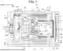

Sources:
- United States Patent and Trademark Office - verify current appl. status at the USPTO↗
Similar patent applications:
- » 20200232453
Control device for electric compressor, electric compressor, air conditioning device for moving object, and method for controlling electric compressor - » 20240166024
ELECTRIC COMPRESSOR CONTROL DEVICE, ELECTRIC COMPRESSOR, AND ELECTRIC COMPRESSOR CONTROL METHOD - » 20190052070
Electric wire lead-in part structure of electric compressor, and electric compressor and shield electric wire provided with same - » 20150214863
Control device of electric sealed compressor, electric sealed compressor apparatus, and home appliance comprising control device and electric sealed compressor apparatus - » 20090315418
Electric wire holding structure for electric compressor and electric wire holding method for electric compressor - » 20170072773
Electric compressor control system and electric compressor for vehicular air conditioning device provided with said system - » 20250317034
ELECTRIC COMPRESSOR CONTROL BOARD AND ELECTRIC COMPRESSOR - » 20090104055
ELECTRIC COMPRESSOR MANUFACTURING METHOD AND ELECTRIC COMPRESSOR - » 20100232982
Control device for electric compressor and start control method of electric compressor - » 20170037858
Electric compressor and method for producing an electric compressor
Recent applications in this class:
- » 20260146606 2026-05-28
CO-ROTATING SCROLL COMPRESSOR - » 20260146605 2026-05-28
CO-ROTATING SCROLL COMPRESSOR - » 20260139673 2026-05-21
CO-ROTATING SCROLL COMPRESSOR - » 20260110298 2026-04-23
SCROLL PLATE COVER AND SCROLL COMPRESSOR - » 20260071623 2026-03-12
CO-ROTATING SCROLL COMPRESSOR - » 20260028986 2026-01-29
SCROLL COMPRESSOR - » 20250207589 2025-06-26
CO-ROTATING SCROLL COMPRESSOR - » 20250207588 2025-06-26
CO-ROTATING SCROLL COMPRESSOR - » 20250146488 2025-05-08
SCROLL COMPRESSOR - » 20250084844 2025-03-13
DRIVE MEMBER FOR SCROLL COMPRESSOR, AND SCROLL COMPRESSOR
Recent applications for this Assignee:
- » 20260146606 2026-05-28
CO-ROTATING SCROLL COMPRESSOR - » 20260139673 2026-05-21
CO-ROTATING SCROLL COMPRESSOR - » 20260125254 2026-05-07
HYDRAULIC BRAKE SYSTEM FOR INDUSTRIAL VEHICLE - » 20260125036 2026-05-07
HYDRAULIC BRAKE SYSTEM FOR INDUSTRIAL VEHICLE - » 20260117770 2026-04-30
ELECTRIC COMPRESSOR - » 20260110282 2026-04-23
EXHAUST GAS RECIRCULATION SYSTEM - » 20260097941 2026-04-09
CARGO HANDLING SYSTEM AND INDUSTRIAL VEHICLE FOR PERFORMING CARGO HANDLING OPERATION - » 20260071624 2026-03-12
ELECTRIC COMPRESSOR - » 20260058481 2026-02-26
POWER STORAGE DEVICE - » 20260025039 2026-01-22
COMPRESSOR