RECIPROCATING RAPID COOLDOWN LOOP FOR CRYOGENIC DEVICES
US20260146789A1
2026-05-28
19/401,190
2025-11-25
Smart Summary: A new cooling system improves how quickly cryogenic devices can cool down. It uses a special loop to move fluid between different parts of the system, which helps transfer heat more effectively. This means that the warmer parts can help cool the colder parts faster. By doing this, the system can reach lower temperatures in less time than older designs. Overall, this technology makes cryogenic systems more efficient and quicker to cool down. 🚀 TL;DR
Abstract:
Cryogenic systems that provide stronger heat transfer between thermalization stages in cryogenic stages compared to conventional systems. The stronger heat transfer can reduce the cooldown time of the cryogenic systems herein compared to conventional systems. The cryogenic systems may include a reciprocating rapid cooldown loop configured to exchange volumes of fluid between different cryogenic stages of the system. The exchanged fluid may be configured to exchange heat between these different stages of the system. This heat exchange allows the lower temperature stages of cryogenic systems to perform initial cooling using the more powerful coolers of the higher temperature stages of the systems. The reciprocating cooldown loop may selectively transfer fluid between a pulse tube cryocooler and other colder stages of the cryogenic system, allowing the powerful pulse tube cryocooler to assist the colder stages of the system, reducing the time required for the initial cooldown of the system.
Inventors:
- Corban I. Tillemann-Dick 26 🇺🇸 Denver, CO, United States
- Kyle J. Thompson 16 🇺🇸 Boulder, CO, United States
- Tyler James Plant 5 🇺🇸 Thornton, CO, United States
Assignee:
- Maybell Quantum Industries, Inc. 15 🇺🇸 Denver, CO, United States
Applicant:
Interested in similar patents?
Get notified when new applications in this technology area are published.
Classification:
F25J1/0269 » CPC main
Processes or apparatus for liquefying or solidifying gases or gaseous mixtures requiring the use of refrigeration, e.g. of helium or hydrogen Details and kind of the refrigeration system used; Integration with other units or processes; Controlling aspects of the process; Start-up or control of the process; Details of the apparatus used; Details of the refrigerant compression system used; Construction and layout of liquefaction equipments, e.g. valves, machines Arrangement of liquefaction units or equipments fulfilling the same process step, e.g. multiple "trains" concept
F25J2270/91 » CPC further
Refrigeration techniques used; External refrigeration, e.g. conventional closed-loop mechanical refrigeration unit using Freon or NH, unspecified external refrigeration by regenerative chillers, i.e. oscillating or dynamic systems, e.g. Stirling refrigerator, thermoelectric ("Peltier") or magnetic refrigeration using pulse tube refrigeration
F25J1/02 IPC
Processes or apparatus for liquefying or solidifying gases or gaseous mixtures requiring the use of refrigeration, e.g. of helium or hydrogen Details and kind of the refrigeration system used; Integration with other units or processes; Controlling aspects of the process
Description
CROSS-REFERENCE TO RELATED APPLICATIONS
This application claims the benefit under 35 U.S.C. 119(e) of U.S. Provisional Application Ser. No. 63/725,393, filed Nov. 26, 2024, under Attorney Docket No. M1567.70004US00, and titled “RECIPROCATING RAPID COOLDOWN LOOP FOR CRYOGENIC DEVICES,” which is hereby incorporated herein by reference in its entirety.
BACKGROUND
Cryogenic systems may include multiple cooling stages, including stages of a cryocooler (such as a pulse tube assembly) and stages of a dilution refrigerator. Such a cryogenic system may be used for achieving low temperatures in a variety of scientific and industrial applications, for example, quantum computing applications.
SUMMARY
According to aspects of the disclosure, there is provided a cryogenic system having a reciprocating cooldown loop, the cryogenic system comprising: a first cooling stage configured to cool to a first stage temperature; a first set of one or more cooling stages configured to cool to respective first set stage temperatures lower than the first stage temperature; and a fluid exchanger configured to selectively transfer fluid between: a first fluid vessel coupled to the first cooling stage; and a first set of one or more fluid vessels, each fluid vessel of the first set of one or more fluid vessels coupled to a respective cooling stage of the first set of one or more cooling stages.
In some embodiments, the first fluid vessel is fluidically coupled to the first set of one or more fluid vessels; the first fluid vessel comprises a first heat exchanger thermally coupled to the first cooling stage; and each fluid vessel of the first set of one or more fluid vessels comprises a heat exchanger thermally coupled to the respective cooling stage of the first set of one or more cooling stages.
In some embodiments, the first heat exchanger is configured to transfer heat between the fluid and the first cooling stage; and the first fluid vessel comprises a first fluid tube, the first fluid tube configured to thermally isolate the first cooling stage from a thermal mass at a temperature higher than the first stage temperature when the first heat exchanger is transferring heat between the fluid and the first cooling stage.
In some embodiments, the fluid exchanger comprises a fluid loop; and the first fluid vessel and the first set of one or more fluid vessels are arranged in the fluid loop.
In some embodiments, the fluid has a mass configured to: fill the first fluid vessel at a first temperature; and fill the first set of one or more fluid vessels at a second temperature.
In some embodiments, the first set of one or more cooling stages comprises: a second cooling stage configured to cool to a second stage temperature lower than the first stage temperature; and a second set of one or more cooling stages configured to cool to respective second set stage temperatures lower than the second stage temperature; and the first set of one or more fluid vessels comprises: a second fluid vessel coupled to the second cooling stage; and a second set of one or more fluid vessels respectively coupled to the second set of one or more cooling stages.
In some embodiments, the fluid exchanger is further configured to selectively transfer the fluid between: the second fluid vessel coupled to the second cooling stage; and the second set of one or more fluid vessels respectively coupled to the second set of one or more cooling stages.
In some embodiments, the fluid exchanger configured to: selectively transfer the fluid between the first fluid vessel and the first set of one or more fluid vessels at a first frequency; and selectively transfer the fluid between the second fluid vessel and the second set of one or more fluid vessels at a second frequency higher than the first frequency.
In some embodiments, the fluid has a mass configured to: fill the first fluid vessel at a first temperature; fill the first set of one or more fluid vessels at a second temperature; fill the second fluid vessel at a third temperature; and fill the second set of one or more fluid vessels at a fourth temperature.
In some embodiments, the fluid exchanger further comprises: a complementary first fluid vessel coupled to the first cooling stage of the cryogenic system; and a complementary first set of one or more fluid vessels respectively coupled to the first set of one or more cooling stages; and the fluid exchanger is further configured to: transfer the fluid from the first fluid vessel to the first set of one or more fluid vessels; and transfer a complementary fluid from the complementary first set of one or more fluid vessels to the complementary first fluid vessel while transferring the fluid from the first fluid vessel to the first set of one or more fluid vessels.
In some embodiments, the fluid exchanger is further configured to: transfer the fluid from the first set of one or more fluid vessels to the first fluid vessel; and transfer the complementary fluid from the complementary first fluid vessel to the complementary first set of one or more fluid vessels while transferring the fluid from the first set of one or more fluid vessels to the first fluid vessel.
In some embodiments, the first cooling stage comprises at least a portion of a pulse tube.
In some embodiments, the fluid exchanger is configured to cool a cooling stage of the first set of one or more cooling stages by selectively transferring the fluid from the first cooling stage to the first set of one or more cooling stages.
In some embodiments, the fluid exchanger is configured to heat at least one of the first cooling stage or a cooling stage of the first set of one or more cooling stages by transferring the fluid from a heat source to the at least one of the first cooling stage or the cooling stage of the first set of one or more cooling stages.
According to aspects of the disclosure, there is provided a method of operating a reciprocating cooldown loop of a cryogenic system having an first cooling stage configured to cool to an first stage temperature and a first set of one or more cooling stages configured to cool to respective first set stage temperatures lower than the first stage temperature, the method comprising: selectively transferring fluid between a first fluid vessel coupled to the first cooling stage and a first set of one or more fluid vessels, each fluid vessel of the first set of one or more fluid vessels coupled to a respective cooling stage of the first set of one or more cooling stages; using the first cooling stage, cooling the fluid while it is disposed in the first fluid vessel; and using the first set of one or more cooling stages, heating the fluid while it is disposed in the first set of one or more fluid vessels.
In some embodiments, cooling the fluid while it is disposed in the first fluid vessel using the first cooling stage comprises transferring heat from the fluid into the first cooling stage using a first heat exchanger; and heating the fluid while it is disposed in the first set of one or more fluid vessels using the first set of one or more cooling stages comprises transferring heat from the first set of one or more cooling stages into the fluid using one or more heat exchangers.
In some embodiments, using the fluid, isolating the first cooling stage from a thermal mass at a temperature higher than the first stage temperature when cooling the fluid while it is disposed in the first fluid vessel.
In some embodiments, selectively transferring the fluid between the first fluid vessel and the first set of one or more fluid vessels comprises: selectively transferring the fluid in a fluid loop.
In some embodiments, the method further comprises: filling the first fluid vessel with the fluid at a first temperature; and filling the first set of one or more fluid vessels with the fluid at a second temperature.
In some embodiments, the first set of one or more cooling stages comprises: a second cooling stage configured to cool to a second stage temperature lower than the first stage temperature; and a second set of one or more cooling stages configured to cool to respective second set stage temperatures lower than the second stage temperature; and the method further comprises: selectively transferring the fluid between a second fluid vessel coupled to the second cooling stage and a second set of one or more fluid vessels respectively coupled to the second set of one or more cooling stages.
In some embodiments, selectively transferring the fluid between the first fluid vessel and the first set of one or more fluid vessels comprises selectively transferring the fluid between the first fluid vessel and the first set of one or more fluid vessels at a first frequency; and selectively transferring the fluid between the second fluid vessel and the second set of one or more fluid vessels comprises selectively transferring the fluid between the second fluid vessel and the second set of one or more fluid vessels at a second frequency higher than the first frequency.
In some embodiments, the method further comprises: filling the first fluid vessel with the fluid at a first temperature; filling the first set of one or more fluid vessels with the fluid at a second temperature; filling the second fluid vessel with the fluid at a third temperature; and filling the second set of one or more fluid vessels with the fluid at a fourth temperature.
In some embodiments, the method of further comprises: transferring the fluid from the first fluid vessel to the first set of one or more fluid vessels; and transferring a complementary fluid from a complementary first set of one or more fluid vessels respectively coupled to the first set of one or more cooling stages to a complementary first fluid vessel coupled to the first cooling stage of the cryogenic system while transferring the fluid from the first fluid vessel to the first set of one or more fluid vessels.
In some embodiments, the method further comprises: transferring the fluid from the first set of one or more fluid vessels to the first fluid vessel; and transferring the complementary fluid from the complementary first fluid vessel to the complementary first set of one or more fluid vessels while transferring the fluid from the first set of one or more fluid vessels to the first fluid vessel.
In some embodiments, the method further comprises: applying selective high or low pressure volumes to the fluid.
BRIEF DESCRIPTION OF DRAWINGS
The accompanying drawings are not intended to be drawn to scale. In the drawings, each identical or nearly identical component that is illustrated in various figures is represented by a like numeral. For purposes of clarity, not every component may be labeled in every drawing. In the drawings:
FIG. 1 shows a reciprocating rapid cooldown loop of a cryogenic system, in accordance with some embodiments described herein.
FIG. 2 shows a method of operating reciprocating rapid cooldown loop of a cryogenic system, in accordance with some embodiments described herein.
FIG. 3A is a schematic diagram of a closed-cycle dilution refrigerator, in accordance with some embodiments described herein.
FIG. 3B is a schematic diagram of another closed-cycle dilution refrigerator, in accordance with some embodiments described herein.
FIG. 3C is a schematic diagram of yet another closed-cycle dilution refrigerator, in accordance with some embodiments described herein.
FIG. 4 is a schematic diagram of helium cleaning devices in a dilution refrigerator such as the dilution refrigerator of FIG. 3C, in accordance with some embodiments described herein.
FIG. 5 is a schematic diagram of a cooldown turbo charger device in a dilution refrigerator such as the dilution refrigerator of FIG. 3C, in accordance with some embodiments described herein.
FIG. 6 is a schematic diagram of a still including a device to separate 3He and 4He using second sound effects, in accordance with some embodiments described herein.
FIG. 7 is an illustrative implementation of a continuous heat exchanger and discrete heat exchanger a dilution refrigerator such as of the dilution refrigerator of FIG. 3C, in accordance with some embodiments described herein.
FIG. 8A is an image of sintered metal particles for use in a heat exchanger.
FIG. 8B is an image of nanowires for use in a heat exchanger, in accordance with some embodiments described herein.
FIG. 8C is an image of a nanocluster for use in a heat exchanger, in accordance with some embodiments described herein.
FIG. 8D includes images of different nanopellets for use in a heat exchanger in accordance with some embodiments described herein.
FIG. 9 is a side view of an illustrative external support rack and integrated lift configured to raise and lower portions of the vacuum chamber, in accordance with some embodiments described herein.
FIG. 10 is an exterior view of a housing configured to support a dilution refrigerator, in accordance with some embodiments described herein.
FIG. 11 depicts, schematically, an illustrative computing device on which aspects of the technology described herein may be implemented.
DETAILED DESCRIPTION
Aspects of the disclosure relate to the field of cryogenics. In particular, the disclosure describes cryogenic systems that provide stronger heat transfer between thermalization stages (e.g., isolated thermalization stages) in cryogenic stages compared to conventional systems. By providing stronger heat transfer between the stages, the cooldown time of the cryogenic systems can be reduced compared to the conventional systems. For example, the cryogenic systems described herein include a reciprocating rapid cooldown loop configured to exchange volumes of fluid between different cryogenic stages of the system. The exchanged fluid may be configured to exchange heat between these different stages of the system. This heat exchange may allow the lower temperature stages of cryogenic systems to perform some initial cooling using the more powerful coolers of the higher temperature stages of the systems. For example, a reciprocating cooldown loop may selectively transfer fluid between a pulse tube cryocooler and other colder stages of the cryogenic system, allowing the powerful pulse tube cryocooler to assist the colder stages of the system, which reduces the time required for the initial cooldown of the system.
Sub-kelvin cryogenic systems are important tools for research in fields such as condensed matter physics, quantum computing, and low-temperature physics experiments. These cryogenic systems are generally comprised of multiple thermalization stages. In conventional systems, the upper (higher temperature) stages may be cooled by powerful cryogenic systems such as Sterling engines, pulse tube cryocoolers, Gifford-McMahon (GM) style cryocoolers, cryogenic liquid volumes, linked to external cooling systems, or other cryogenic systems to reach temperatures below 4 Kelvin (or as low as about 2 Kelvin). In some embodiments, to reach temperatures below 1 Kelvin, a cryogenic system may include fewer cooling cycles that are less powerful, such as Joule-Thomson, adiabatic demagnetization, or dilution cycles.
In conventional systems, lower temperature cooling cycles (such as the cycles described above) may achieve temperatures as low as a few millikelvin, but offer cooling powers of only a few microwatts to milliwatts at the lowest temperatures. Due to the low cooling power of conventional cryogenic systems at low temperatures, removing the enthalpy or lowering the temperature of these high heat capacity plates can take 24-36 hours or more, which may can extend to 40-100 s of hours or more when the lower stages include components with large thermal masses, such as may be used for large-scale experiments or superconducting magnets.
Some conventional systems may attempt to accelerate cooldown, such as by using gas gap heat switches, controlled mechanical switches, superconducting switches, or others. However, conventional approaches are limited by low thermal transport and high costs that are often driven by requirements for extremely tight tolerances. These conventional systems can also be ineffective for cooling to desired temperatures, such as those below about 15 Kelvin, making them cumbersome for cooling to the ultra-low temperatures desired for certain applications. Other conventional approaches have even more severe limitations, such as requiring liquid cryogens (which may be one time use), mechanical cryogenic switches, or other low-reliability components.
The disclosure provides a reciprocating rapid cooldown loop for use with cryogenic systems. The reciprocating rapid cooldown loop provides substantial improvements to cooldown times of cryogenic systems compared to conventional systems while remaining more cost effective that these conventional systems, and more physically robust. Accordingly, the reciprocating rapid cooldown loop described herein addresses the issues of long cooldown times with costly and only marginally effective accelerants. In particular, the reciprocating rapid cooldown loop improves thermal communication within the cryogenic system during initial cooling phases of the cryogenic system, and may also minimize thermal communication once target temperatures are reached, and may further be used in reverse to warm the system back up. The reciprocating rapid cooldown loop provides sub-kelvin cryogenic systems that take full advantage of the cooling power of warmer cryogenic stages without using cryogenic switches or liquid cryogens. As such, the reciprocating rapid cooldown loop enhances the efficiency of the cooling process of the cryogenic system and dramatically reduces the cooldown time of the system, without using high cost or high-precision manufactured components.
As described herein, a reciprocating rapid cooldown loop uses a controlled cyclical pumping mechanism in order to selectively transfer a fluid (e.g., a gas, a liquid, a substance including both gas and liquid phases, or a substance having properties of both gas and liquid phases) volume between different temperature stages within the cryogenic system, improving thermal communication during the cooldown process. Selectively transferring the fluid may comprise transferring the fluid between different stages of the cryogenic system depending on whether certain stages are desired to be cooled and/or whether the fluid is desired to be cooled, which may change over time. For example, the selectively transferring the gas may comprise reciprocating the comprise between warmer and colder stages of the system in order to continuously cool the warmer stage using the colder stage. The frequency of the selective transfer or reciprocation may be based on the heat transfer dynamics between the fluid and the stages.
The reciprocating rapid cooldown loop may also modify fluid transfer, such as by stopping or changing the transfer of fluid, and/or may have the thermal exchange fluid removed. For example, the reciprocating rapid cooldown loop may modify fluid transfer when the system reaches target low temperatures. Modifying the fluid transfer may allow the system to minimize unwanted thermal communication within the system. A reciprocating rapid cooldown loop may operate by cyclically transferring specific volumes of fluid from the upper stages of the cryogenic systems refrigerator that are directly cooled by the upper stage cryocoolers (such as pulse tubes or other powerful cooling systems), to the lower, colder stages that are not directly attached to the upper stage cryocoolers. Accordingly, the reciprocating rapid cooldown loop provides effective thermal communication between different stages of the cryogenic systems during initial cooldown phases, providing a uniform temperature reduction across the stages. As described in more detail below, the reciprocating rapid cooldown loop may include one or more volumes of exchange fluid (e.g., helium) held at different pressures, connected by a controlled valve. The valve alternates the fluid flow between these two pressure volumes, enabling the reciprocation of fluid within the cooling loop.
The reciprocating rapid cooldown loops and related cryogenic systems described herein provide various advantages compared to conventional cryogenic systems. In various embodiments, the reciprocating rapid cooldown loops provide substantially faster cooldown times compared to conventional systems. The cooling efficiency of cryogenic systems that incorporate a reciprocating rapid cooldown loop is enhanced, as cooling of lower stages may be hastened by the cooling power of upper cooling stages (such as a cryocooler). Providing thermal communication between more powerful upper stages and less powerful lower stages therefore allows for much faster cooldown times compared to conventional approaches, impacting the overall effectiveness and readiness of the dilution refrigerator for experimental use. Cryogenic systems that incorporate a reciprocating rapid cooldown loop may have better cost efficiency compared to conventional systems. A reciprocating rapid cooldown loop eliminates the need for precision-engineered gas gap switches and other expensive components, reducing production costs and complexity. Reciprocating rapid cooldown loops also provide improved scalability and flexibility. The tubes and valve system of the reciprocating rapid cooldown loop may have a modular design allowing the loop to have different sizes and arrangements suitable for different configurations of cryogenic systems, allowing the reciprocating rapid cooldown loops to scale for different research needs. Reciprocating rapid cooldown loops also have greater operational flexibility compared to conventional systems because the reciprocating rapid cooldown loops function effectively at temperatures well below the operational limits of traditional gas gap heat switches, thereby extending the usable temperature range of cryogenic systems.
The inventors have recognized that, in various heat transfer applications, using a forced fluid to transfer heat from one location to another may be preferable. The forced fluid may provide advantages over conventional techniques such as conductive heat transfer. For example, conductive heat transfer may provide low heat flux over anything other than very small distances. In a moving fluid heat transfer system conduction works over much smaller distances than the distance between the two temperature reservoirs, compared to a conductive heat transfer system where conduction must work over the entire distance. Accordingly, for large heat loads over moderate or larger distances, a system using conduction may have slow heat transfer or may need prohibitively large cross-sectional areas for adequate heat transfer. Therefore, conductive heat transfer systems may have high costs and impractical designs.
Furthermore, the techniques described herein provide improved heat transfer compared with gas gap systems. In a gas gap system, thermal transport may be heavily dominated by thermal conduction in the fluid, because the gap between thermal masses is relatively small such that significant convection may not be possible, and because the thermal gradient may not be arranged along the direction for natural convection. Compared with conventional gas gap systems, a reciprocal fluid exchanges as described herein has various advantages. For example, a fluid exchanger may have lower manufacturing tolerances compared to a gas gap heat switch (GGHS). A GGHS uses exceptionally small gaps in order to provide good thermal transport across the gap, and when making and installing a GGHS, the hot and cold side may short against one another, ruining the GGHS. A fluid exchanger may also have reduced manufacturing complexity, using valves and pumps as compared to mechanical switches of a GGHS. A fluid exchanger, compared to a superconducting switch, may not use magnetic fields, and thus may be operable over a far wider range of temperatures compared to the restricted temperature ranges of the superconducting switches. A fluid exchanger also provides improved isolation compared with heat switch techniques, such that the heat link between thermal masses in an off state is much smaller than in the GGHS. A fluid exchanger may also warm a system in addition to cooling it, reducing the number of couplings needed inside the system compared with a GGHS. A fluid exchanger may provide increased cooling and heating power during operation compared with a GGHS. A fluid exchanger may also provide finer heat transfer control compared with a GGHS, as thermal transport between thermal masses of the system may be externally controlled such that the system can automatically, or based on user input, select which thermal masses are placed into thermal communication. As such, systems described herein overcome the limitations of conventional conductive systems (such as gas gap systems) by thermally coupling different thermal stages using a moving fluid coolant.
The cooling stages described herein may comprise different temperature stages of pulse tube cryocoolers, dilution refrigerators, and other cryocoolers (e.g., Sterling engines, GM style cryocoolers, etc.). The disclosure provides rapidly cooling cryogenic systems that address cooldown time limitations associated with conventional existing arrangements of cryogenic systems and methods. Aspects of the disclosure further provide more efficient, effective, and compact cryogenic systems and methods, in order to achieve low temperatures. In some embodiments, low temperatures may include temperatures suitable for scientific and industrial applications, for example, quantum computing applications, and may include temperatures below 10K, 8K, 6K, or 300 milliKelvin. For example, the system may be used during an initial cooling operation to below 6K, such as an initial cooling operation to about 5K. Embodiments of the disclosure described herein may provide more efficient, effective, and compact systems and methods through better integration of a regenerative cycle cooler, such as a 4.2 Kelvin Pulse Tube with a sub-Kelvin dilution unit.
Pulse tube cryogenic systems and dilution refrigerators are two techniques for achieving low temperatures in a variety of scientific and industrial applications. A pulse tube cryogenic system may comprise a specialized type of modified sterling engine that operates by compressing and expanding helium gas through a series of valves, heat exchangers, and regenerators, to ultimately generate an intermediate low temperature. For example, intermediate low temperatures may comprise temperatures around 2-4.2 Kelvin. In other embodiments, the intermediate low temperature may be as high as about 7 Kelvin, about 10 Kelvin, or about 50 Kelvin.
A dilution refrigerator may operate using a mixture of helium-3 and helium-4 isotopes to achieve low temperatures. For example, low temperatures may include temperatures as low as a few millikelvin. In some embodiments, a mixture is first liquefied by cooling it with an alternative system. For example, this liquefied mixture may be initially cooled through using a Joule-Thomson expander and then a series of heat exchangers, until a critical temperature is reached. In some embodiments, this critical temperature may be around 870 milliKelvin. At the critical temperature, a spontaneous phase separation may occur into two fractions, a first fraction rich in helium-3 and a second fraction rich in helium-4. The dilute phase may be pumped with sufficient pressure and at appropriate temperatures. When the dilute phase is pumped, the natural ratio in the dilute phase may be disrupted due to the higher vapor pressure of helium-3. The heat of mixing associated with helium-3 crossing the phase boundary to correct this ratio may allow a cryogenic system to cool to low temperatures, such as temperatures as low as a few millikelvin. The resulting cooling power provided by the cryogenic system may be used to cool and study various materials and phenomena, such as superconductivity and quantum mechanics.
In some embodiments, to operate, a helium-3 and helium-4 mixture of a dilution refrigerator is first be brought to an intermediate low temperature, for example, of about 4.2 Kelvin or lower. According to various embodiments, techniques for achieving this intermediate low temperature or initializing temperature, include, among other techniques, helium baths, staged nitrogen-helium baths, Gifford-McMahon cryocoolers (GM), GM-style pulse tubes, or Stirling-style pulse tubes (together, “pulse tubes”).
I. Reciprocating Rapid Cooldown Loop
FIG. 1 shows a reciprocating rapid cooldown loop of a cryogenic system. FIG. 1 illustrates a cryogenic system 1000 having a reciprocating cooldown loop 1002. The reciprocating cooldown loop 1002 may comprise a plurality of fluid vessels coupled with respective stages of the cryogenic system.
Respective fluid vessels may be fluidically coupled with other ones of the fluid vessels. As such, fluid may flow (e.g., may be forced by the system) between different ones of the fluid vessels. In some embodiments, a fluid vessel may comprise a fluid tube. The fluid tube may be configured to isolate different cooling stages or thermal masses, as described below. In some embodiments, a fluid vessel may comprise a heat exchanger. A heat exchanger may thermally couple the fluid to one or more cooling stages, such that the fluid and the cooling stage may transfer heat therebetween. In some embodiments, the fluid tube may also thermally couple the fluid to one or more cooling stages. In some embodiments, the heat exchanger may also isolate different cooling stages or thermal masses. As such, a fluid vessel may include either or both of a fluid tube and a heat exchanger and may be configured to both isolate different cooling stages or thermal masses, as well as to thermally couple the fluid to one or more of the cooling stages.
In the illustrative embodiment of FIG. 1, the reciprocating cooldown loop 1002 comprises fluid tubes 1004a-1010a. In some embodiments, the reciprocating cooldown loop 1002 may also comprise complementary fluid tubes 1004b-1010b, as well as valve 1014 and coupling portion 1016. In the embodiment of FIG. 1, coupled to the reciprocating cooldown loop 1002 is a pressure source comprising a high pressure volume 1012a and a low pressure volume 1012b.
The reciprocating cooldown loop 1002 accelerates thermal equilibrium within cryogenic system using current coldest states of the cryogenic system by selectively transferring fluid between the different stages. For example, the reciprocating cooldown loop 1002 may be configured to place warmer or warmest parts of the system into thermal communication with colder or coldest parts of the cryogenic system 1000. In some embodiments, the reciprocating cooldown loop 1002 places different parts of the cryogenic system into thermal communication by oscillating a fluid mass (e.g., a mass of helium gas) between those different parts of the system. In some embodiments, the reciprocating cooldown loop 1002 may be configured to place any actively cooled stages of the cryogenic system 1000 into thermal communication with stages configured to reach eventually lower temperatures. Moreover, the reciprocating cooldown loop 1002 may also be configured to place different stages of the cryogenic system 1000 into thermal communication without exposing lower stages to higher temperatures, such as room temperature.
As shown in FIG. 1, the cryogenic system 1000 comprises one or more cooling stages 1018-1024. Each cooling stage may be coupled to one or more fluid vessels, such as one or more of fluid tubes 1004a-1010a and/or a heat exchanger. Each cooling stage may also be coupled to a complement fluid vessel, such as a fluid tube in the group of fluid tubes 1004b-1010b and/or a heat exchanger. For example, a first cooling stage 1018 may be coupled to fluid tube 1004a and complementary fluid tube 1004b. A second cooling stage 1020 may be coupled to fluid tube 1006a and complementary fluid tube 1006b. A third cooling stage 1022 may be coupled to fluid tube 1008a and complementary fluid tube 1008b. A fourth cooling stage 1024 may be coupled to fluid tube 1010a and complementary fluid tube 1010b. Furthermore, a respective heat exchanger may thermally couple a cooling stage with the fluid when the fluid is at or around each fluid tube.
Each fluid vessel coupled with a cooling stage, such as each fluid tube and/or each exchanger coupled to a cooling stage may be configured to exchange heat with that respective cooling stage. For example, each thermalization stage within the cryogenic system may have one or more heat exchangers that are coupled to the fluid tubes of the reciprocating cooldown loop 1002. Such heat exchangers may be configured to transfer of thermal energy between the reciprocating cooldown loop 1002 and the different thermalization stages. The heat exchangers may therefore ensure that heat is efficiently absorbed or released, depending on the direction of the fluid flow and the current cooling needs of the system. In other words, when fluid in a respective fluid tube has a higher temperature than a coupled cooling stage, the fluid may cool and the cooling stage may heat. Likewise, when fluid in a respective fluid tube has a lower temperature than a coupled cooling stage, the fluid may heat and the cooling stage may cool.
A first cooling stage may be a cooling stage configured to reach a highest temperature, while each next cooling stage may be configured to reach a subsequently lower temperature. For example, the first cooling stage may be configured to reach 50 Kelvin, the second cooling stage may be configured to reach 9K, the third cooling stage may be configured to reach 4K. and the fourth cooling stage may be configured to reach 2 Kelvin. It should be appreciated that these temperatures are merely exemplary, and the disclosure is not limited in this regard.
Fluid tubes may be referred to as upper or lower (or first, second, third, etc.) depending on their arrangement in the temperature hierarchy of the cryogenic system 1000. For example, fluid tube 1004a and fluid tube 1004b may be referred to as upper fluid tubes, while fluid tubes 1006a-1010a and fluid tubes 1006b-1010b may be referred to as lower fluid tubes. Specifically, fluid tubes 1006a-1010a and fluid tubes 1006b-1010b may make up a first set of lower fluid tubes. This is because fluid tube 1006a and fluid tube 1006b may be considered first lower fluid tubes while fluid tubes 1008a-1010a and fluid tubes 1008b-1010b are considered a second set of lower fluid tubes (this second set of lower fluid tubes being a subset of the first set of lower fluid tubes). Similarly, fluid tube 1008a and fluid tube 1008b may be considered second lower fluid tubes while fluid tube 1010a and fluid tube 1010b are considered a third set of lower fluid tubes (this third set being a subset of both the second set of lower fluid tubes and the first set of lower fluid tubes), with fluid tube 1010a and fluid tube 1010b also being third lower fluid tubes. Moreover, while FIG. 1 shows four levels of fluid tubes, this is not limiting, and the reciprocating cooldown loop 1002 may include further fluid tubes above or below the illustrated fluid tubes.
In order to transfer heat between different stages of the cryogenic system, the reciprocating cooldown loop 1002 may selectively transfer (e.g., by reciprocating) a fluid or gas slug between the different fluid tubes. The cooling power of higher temperature stages may be used to cool lower temperature stages faster by reciprocating fluid between these different stages. Moving fluid to a lower temperature stage causes the fluid to be heated (and the lower stage to be cooled) while moving the fluid to an upper stage causes the fluid to be cooled (using the cooling power of the higher temperature stage). Additionally, in some embodiments, heat from a heat source such as a higher temperature stage or an external heat sources outside the cryogenic system may be used to heat stages faster by reciprocating fluid between different stages. As such, the reciprocating cooldown loop 1002 may transfer fluid within the cryogenic system in order to transfer heat between stages. For example, heated fluid may be transferred from a thermal mass at ambient temperature or from a higher temperature stage, into cooler stages of the cryogenic system, in order to heat up the various stages of the cryogenic system.
The heating process may be used to warm up a cryostat or other cryogenic component. For example, when a cryogenic system has finished performing a desired set of tasks, e.g., when it is done making measurements, various components of the system (e.g., a set of cold plates) are cold and may be brought to room temperature. Accordingly, the reciprocating fluid loop may also be operable to bring heat into the system from a surrounding environment or other heat source (such as by using a heat exchanger above or on a top plate surrounded by air or a heat sink surrounded by liquid, such by being disposed in a building water supply) down to the plates inside the system that are cold. For example, in a heating operation, the fluid loop may transfer fluid in one direction (e.g., with no fluid oscillation), or with a low frequency of oscillation. During the heating operation, the fluid may be forced from a heat source to one or more cold stages. For example, during the heating operation, the fluid may be flowed all of the way across a fluid vessel that is arranged between a heat source (e.g., an ambient or room temperature thermal mass) and a first, warmest stage of cryogenic system. Flowing the fluid across that fluid vessel may thermally couple the heat source and the cryogenic system, thereby transferring heat from the heat source into one or more stages of the cryogenic system. Conventional cryogenic systems may take around 8 or more hours to warm up the system (e.g., using electrical heaters), but the systems described herein may warm faster by using the reciprocating fluid loop heating operation, such as by warming in 4, 2, 1, or fewer hours.
The fluid tubes may have varied sizing to ensure improved heat transfer. In some embodiments, the reciprocating cooldown loop 1002 incorporates fluid tubes 1004a-1010a and 1004b-1010b having progressively decreasing diameter from upper to lower stages. These changes in diameter correspond to the upper and lower stages of cooling, from the higher temperatures (such as 50 Kelvin) down to the lower stages (such as 4 Kelvin and below). In some embodiments, at each stage, the volume of a fluid tube is provided such that the volume of fluid may fill all of the fluid tubes below that fluid tube. For example, in a system with a 50 Kelvin stage, a 9 Kelvin stage, a 4 Kelvin stage, and at least one lower stage, at the 50 Kelvin stage, the tube volume is sufficient to fill the entire volume below 50 Kelvin, which may occur at a specific frequency or displacement. At the 9 Kelvin stage, the tube volume is sufficient to fill the entire volume below 9 Kelvin, which may occur at a higher switching frequency and/or lower displacement. At the 4 Kelvin stage, the tube volume is sufficient to fill the entire volume below 4 Kelvin, which may occur at an even higher frequency and/or further reduced displacement.
As noted above, the fluid tubes may comprise varied tube diameters in order to control displacement of the fluid flow in different sections of the fluid loop. According to some embodiments, this may be illustrated with governing equations for reciprocating flow. Using constant volume flow (e.g., neglecting changes in temperature) and sinusoidal flow, the following Equation (1) for flow velocity in terms of volume flow rate and tube area can be used, where u1 represent flow velocity at tube section 1, U1 represents volume flow at tube section 1, and ATube represents tube area at tube section 1.
u 1 = U 1 / A Tube ( 1 )
Accordingly, the following Equation (2) may be used for displacement, with ξ1 representing displacement at section 1, f indicating frequency of the sinusoidal flow, and ω representing angular frequency of the sinusoidal flow.
ξ 1 = u 1 2 π f = u 1 ω = U 1 ω A Tube ( 2 )
Using a constant value of U1, it may be appreciated that ξ1 may be varied by varying the value of ATube. For example, when U1 and the frequency ω are held constant and the value of ATube is varied, the displacement ξ1 varies with inverse proportionality to ATube. In the case of a round tube the area may be varied by simply changing the diameter. Accordingly, although other factors also affect the displacement, it may be readily appreciated that when ξ1 is much smaller than the distance between the two cooling stages or thermal masses, heat transfer across said stages may be reduced compared to if ξ1 were larger than said distance between the stages. Accordingly, the fluid displacement may be sized such that it is: (a) smaller than the distance between two cooling stages or thermal masses that are to be isolated; and/or (b) larger than the distance between two cooling stages or thermal masses between which heat is to be transferred. Thus, the system may operate with a fluid displacement that isolates one set of cooling stages or thermal masses from each other while transferring heat between another set of cooling stages or thermal mass.
The reciprocating cooldown loop may also prevent unwanted heat transfer. As described herein, prevention of unwanted heat transfer is a consideration in fluid tube sizing. In an illustrative example, the pressure source is at a room temperature of 300 Kelvin, while the fluid tube 1004a is coupled to first stage 1018, configured to reach 50 Kelvin, and the fluid tubes 1006a-1010a are configured to reach lower temperatures, with fluid tube 1006a coupled to second state 1020 configured to reach 10 Kelvin. A first fluid or gas slug may be initially disposed in fluid tube 1004a and may fill that tube. The first fluid or gas slug may have a mass such that it fills the volume of the fluid tube 1004a at the temperature of the coupled first stage 1018, 50 Kelvin. Furthermore, because the pressure source is at room temperature, there may be a second fluid or gas slug above the fluid tube 1004a with a temperature between 50 Kelvin and 300 Kelvin. At a second time, the reciprocating fluid cooldown loop 1002 may move the slugs, and the first slug may move towards fluid tube 1006a and lower fluid tubes. The first slug that is at 50 Kelvin may be sized to fill all of the fluid tube 1006a (and may also fill the fluid tubes 1008a-1010a) so that this tube and its coupled second stage 1020 (as well as any lower tubes and stages) are not exposed to the second slug having higher temperatures between 50 Kelvin and 300 Kelvin.
As such, the reciprocating cooldown loop 1002 has particular sizing of each of the fluid tubes 1004a-1010a and 1004b-1010b to ensure enhancing cooling. Each fluid tube may be sized such that when fluid slug is transferred between different portions of the reciprocating cooldown loop 1002, that fluid tube is not exposed to fluid that is too warm. For example, the size of the fluid tubes may be set (and the corresponding mass of the slug may also be set) so that no fluid tube is ever exposed to a temperature warmer than the current stage being used for cooling. For example, in a first part of the cooling process, the reciprocating cooldown loop 1002 acts to set the entire cryogenic system 1000 to the temperature of the first stage, which is coupled with fluid tubes 1004a and 1004b. At a first time, a slug is disposed in fluid tube 1004a and fills the volume of that tube. At a second time, the reciprocating cooldown loop 1002 moves the slug to fill all of the tubes below that tube, namely, fluid tubes 1006a-1010a. The fluid tubes 1004a-1010a are sized such that the slug will fill those lower fluid tubes 1006a-1010a and ensure that no additional fluid from comes from above fluid tube 1004a and into contact with any of the lower fluid tubes.
Accordingly, the reciprocating cooldown loop 1002 may comprise a large enough volume of fluid in the slug in order to prevent unwanted heat transfer. In particular, the fluid volume may be sized with sufficient volume is to avoid contact between room temperature fluid from the pressure source (e.g., at about 300 Kelvin) and the low temperature cryogenic stages of the cryogenic system 1000. For example, fluid at fluid tube 1004a may be sufficient to reach each of fluid tubes 1006a-1010a without exposing those fluid tubes to room temperature fluid. When cooling progresses to intermediate stages that have temperatures below a temperature of the uppermost stage, the slugs may also prevent the lower stages from coming into contact with fluid having the temperature of the uppermost stage, and so on, as the cooling progresses to colder and colder stages.
In some embodiments. two portions of the reciprocating cooldown loop 1002 may act in congress. One portion of the loop may be fluid tubes 1004a-1010a and the other portion may be fluid tubes 1004b-1010b. These two portions of the reciprocating cooldown loop 1002 may operate 180 degrees out of phase with each other. For example, when fluid is moving downwards in the fluid tubes 1004a-1010a, fluid is also moving upwards in the fluid tubes 1004b-1010b. When fluid is moving upwards in the fluid tubes 1004a-1010a, fluid is also moving downwards in the fluid tubes 1004b-1010b. Further, when fluid is disposed in fluid tube 1004a and being cooled, fluid is also disposed in fluid tubes 1006b-1010b and being warmed. When fluid is disposed in fluid tubes 1006a-1010a and being warmed, fluid is also disposed in fluid tube 1004b and being cooled. By operating two portions of the loop out of phase, the cryogenic system may cause the powerful upper stage coolers to always be cooling at least some fluid for use in cooling the lower stages.
The reciprocating cooldown loop 1002 also includes a loop portion 1016 coupling the fluid tube 1010a and fluid tube 1010b. By coupling these two fluid tubes, the reciprocating cooldown loop 1002 forms a loop, which allows the high and pressures exposed to one side of the loop to cause fluid in the loop to move in congress as described above.
In some embodiments, the cryogenic system 1000 may include only one set of fluid tubes. For example, the cryogenic system 1000 may include the fluid tubes 1004a-1010a and not include the fluid tubes 1004b-1010b. As such, cryogenic system 1000 may oscillate fluid between the various ones of the fluid tubes 1004a-1010a without complementary oscillation in a complementary set of tubes. For example, the fluid may be selectively moved in the one set of fluid tubes to thermally couple with various stages of the cryogenic system 1000, as described herein.
The reciprocal path of fluid in the reciprocating cooldown loop 1002 may be set based on the temperature of the cryogenic system 1000. As the cryogenic system 1000 cools to lower temperatures, the reciprocating cooldown loop 1002 may begin to shorten the path of the fluid, reciprocating the fluid between only some of the lower stages of the system. For example, while cooling the cryogenic system 1000 to the temperature of the first stage, the reciprocating cooldown loop 1002 may reciprocate fluid between the first stage and all of the stages beneath the first stage. However, once the entire cryogenic system 1000 has reached the temperature of the first stage, fluid may begin to reciprocate between just the second stage and all of the stages beneath the second stage. This may be repeated for every stage as those stage temperatures are reached. In other words, once the second stage and all of the stages beneath the second stage reach the temperature of the second stage, fluid may begin to reciprocate between just the third stage and all of the stages beneath the third stage, and so on, until each stage reaches its target temperature. In this manner, fluid may be reciprocated, and cooling may be performed based on the temperature of the lowest stage of the system. Moreover, the cooling may be performed from the warmed to the coldest stages.
The cryogenic system 1000 may dynamically adjustment of cooling parameters such as frequency and volume of fluid transfer. For example, the cryogenic system 1000 may adjust the frequency with which fluid is cycled in the system and/or adjust the volume of displaced volume of fluid in the cycle. The system may adjust the frequency and volume based on temperature feedback from the differential thermalization stages. By adjusting frequency and/or volume of fluid cycling, the cryogenic system 1000 may ensure optimal thermal management throughout the cooldown process, from initial high-temperature stages to the final 20) low-temperature conditions necessary for sensitive experimental operations.
Frequency of reciprocation of the fluid may be based on the volume of the different fluid tubes, as well as on the temperature differential between the fluid and the stages being cooled. Furthermore, in some embodiments, the frequency of reciprocation may change during the cooling process. In various embodiments, the frequency of reciprocation may be lower for warmer stages of the cryogenic system and may increase as fluid begins to reciprocate from colder stages of the cryogenic system. This may be because the volume of the fluid tubes for lower stages may be smaller, and/or because there may be lower temperature differentials at later parts of the cooling process. Volume of the fluid tubes for lower stages may be smaller because the fluid may be denser due to lower temperatures, and the fluid tubes may also be smaller because of the tube sizing considerations discussed above for ensuring fluid tubes are not exposed to warmer fluid. Timing of reciprocation may affect the efficiency of the system, as too low of a frequency may result in time where equilibrium is reached and no heat is being exchanged, while too high of a frequency may result in time where additional cooling that could have been performed was not achieved. Additionally, fluid volume should not be so low that heat transfer is insignificant.
Flow of fluid in the reciprocating cooldown loop 1002 may be close to laminar rather than perfectly turbulent. In various embodiments the fluid flow may be substantially laminar, such as with a Reynolds number of around 800, where a Reynolds number of 2000 generally indicates turbulent flow. Moreover, the fluid flow may be in a viscous flow regime.
The system may include a controller configured to control the pressure source to provide the fluid reciprocation. For example, the controller may comprise one or more valves coupled to the pressure source and configured to selectively couple the pressure source to the fluid. In some embodiments, the pressure source may comprise one or a plurality of pressure reservoirs. As such, the one or more valves may operate between a plurality of pressure reservoirs to control the pressure applied to the fluid exchanger. As described above, the pressure source may comprise high pressure volume 1012a and low pressure volume 1012b. The valve 1014 may be used to expose parts of the reciprocating cooldown loop 1002 to the high-pressure volume 1012a while exposing a different part of the reciprocating cooldown loop 1002 to the low-pressure volume 1012b. The cryogenic system 1000 may use the high and low pressure volumes as buffer volumes to cause oscillation of fluid within the cooling loop. In some embodiments, the pressure source may be pressurized by one or more pumps or one or more pistons. For example, the pressure source may include two pneumatic pistons operating out of phase from one another, with one piston coupled to each side of the fluid loop.
The pressure source may be held at room temperature. The pressure source may also be controlled at room temperature. For example, the pressure source may be an external compressor coupled to the cross valve at room temperature. As discussed above, in some embodiments, fluid tubes and slugs may be sized to ensure that room temperature fluid from the pressure source (or other sources) does not come into contact with stages of the cryogenic system 1000 that are being cooled.
Cryogenic system 1000 also includes a valve 1014 configured to interface a pressure source with the reciprocating cooldown loop 1002. As shown in FIG. 1, the pressure source may comprising both high pressure volume 1012a and low pressure volume 1012b. Valve 1014 may be arranged to have multiple states that regulate which side of the reciprocating cooldown loop 1002 is exposed to which pressure volume. By exposing the reciprocating cooldown loop 1002 to the different pressure volumes, fluid may reciprocate with the reciprocating cooldown loop 1002 and thermal energy may be transferred from warmer to colder stages within the cryogenic system 1000. In a first state, high pressure volume 1012a may be exposed to fluid tubes 1004a-1010a, while low pressure volume 1012b is exposed to fluid tubes 1004b-1010b. This state may cause fluid to travel from the upper tubes of fluid tubes 1004a-1010a to the lower tubes of that group, while fluid may also travel from the lower tubes of fluid tubes fluid tubes 1004b-1010b to the upper tubes of that group. In a second state, high pressure volume 1012a may be exposed to fluid tubes 1004b-1010b, while low pressure volume 1012b is exposed to fluid tubes 1004a-1010a. This state may cause fluid to travel from the lower tubes of fluid tubes 1004a-1010a to the upper tubes of that group, while fluid may also travel from the upper tubes of fluid tubes fluid tubes 1004b-1010b to the lower tubes of that group. Moreover, the valve 1014 may have a state where no pressure volume is exposed to the fluid tubes, which may cause fluid to not move. Valve 1014 may be a cross valve or may be a set of two or more valves. Such a cross valve may e arranged to change which side the high and low pressure volumes are exposed to, allowing the swapping of sides. The valve 1014 may reciprocate in a manner set based on the desired frequency of the fluid reciprocation.
The cryogenic system 1000 may cool in in multiple stages. In an initial phase the cryogenic system may become isothermal to the most powerful cooling stage, such as first cooling stage 1018. As the cryogenic system begins to cool, the reciprocating cooldown loop 1002 transfers a relatively larger volume of fluid from the stages being cooled (cooling stages 1020-1024) with the most powerful cooling stage (cooling stage 1018) which may be a primary stage of a pulse tube configured to reach about 50 Kelvin. As such, fluid may be reciprocated 20) between fluid tube 1004a and fluid tubes 1006a-1010a, and also between fluid tubes 1006b-1010b and has tube 1004b.
In an intermediate phase the system may reach isothermal operation with intermediate cooling stages. As the system approaches isothermality with the highest stage (e.g., around 50 Kelvin in the example above), the frequency of oscillations and/or volume of fluid transfer is changed so that the first cooling stage 1018 no longer communicates with the lower stages of the cryogenic system. This adjustment results in a reduced volume of fluid being moved per cycle. For example, the reciprocating cooldown loop 1002 may transfer a smaller volume of fluid from the stages being still being cooled (cooling stages 1022-1024) with the next most powerful cooling stage (cooling stage 1020). As such, fluid may be reciprocated between fluid tube 1006a and fluid tubes 1008a-1010a, and also between fluid tubes 1008b-1010b and has tube 1006b. A decrease in volume per cycle allows stages such as the regenerator stage (around 9 Kelvin) or the Pulse Tube secondary stage (around 2 Kelvin) to induce isothermality with the lower thermalization stages of the system. The steps of the intermediate phase may be repeated for each lower stage of the cryogenic system.
In a final stage, thermal isolation is performed. Upon reaching an appropriate base temperature (e.g., ˜5 Kelvin for helium exchange fluid) uniformly across the refrigerator, the reciprocating cooldown loop 1002 may evacuate exchange fluid from the fluid tubes, leaving a near vacuum within the loop. The evacuation and resulting vacuum reduces or substantially eliminates any residual thermal communication between the different thermalization stages, which may ensure that lower stages reach and maintain ultralow temperatures necessary for sensitive experimental conditions without interference from any warmer stages.
A cryogenic system may perform a cooling operation to lower the temperature of components of the system. During the cooling operation, the system may force fluid through the components of the system to cool those components (e.g., said components may be the plumbing of the system). During a cooling operation, the limited thermal conductivity between thermalization plates of the cooling stages and discrete heat exchangers may reduce cooling efficiency of the system or increase a cooling time of the system. For example, discrete heat exchangers of the system may undesirably stay warm after thermalization plates of the system have reached desired temperatures for starting circulation. Accordingly, in some embodiments, the systems described herein may cool the discrete heat exchangers to reach or approach the same temperature as the plates, in order to bring the system to base temperature. In some embodiments, due to high flow impedance of the fluid loop, the system may not be able to simply start fluid circulation. Furthermore, even if circulation were to be started, the series of heat exchangers between the discrete heat exchangers and the plates (including the discrete heat exchangers themselves) thermally insulates the circulating fluid from the hot discrete heat exchangers, limiting the effectiveness of heat removal.
Accordingly, in some embodiments, the system may cool the discrete heat exchangers efficiently using fluid, thus increasing cooling efficiency of the system and/or reducing the cooling time of the system. For example, the system may reciprocate fluid through the plumbing (e.g., a lower-impedance side of plumbing such as the still-pumping line) by oscillating the pressure applied to the plumbing. In some embodiments, the pressure may be oscillated from a low pressure of about 0.15 bar to a high pressure of about 1.5 bar. In some embodiments, the pressure may be oscillated at a frequency of about 3 Hz. The oscillation of the fluid in these portions of the plumbing may efficiently transport heat away from the discrete heat exchangers into colder plates, resulting in the cryogenic system reaching temperatures low enough to begin conventional dilution unit operation.
FIG. 2 shows a process flow 2000 for a method of operating a reciprocating cooldown loop of a cryogenic system. As described above, the cryogenic system may be cryogenic system 1000 having an upper cooling stage configured to cool to an upper stage temperature and a first set of one or more lower cooling stages configured to cool to respective lower stage temperatures lower than the upper stage temperature. As illustrated in FIG. 2, the process flow 2000 includes a step 2002, a step 2004, and a step 2006. At step 2002, the reciprocating cooldown loop may selectively transfer fluid between an upper fluid tube coupled to the upper cooling stage and a first set of one or more lower fluid tubes respectively coupled to the first set of one or more lower cooling stages; using the upper cooling stage. At step 2004, the cryogenic system may cool the fluid while it is disposed in the upper fluid tube; and using the first set of one or more lower cooling stages. At step 2004, the cryogenic system may heat the fluid while it is disposed in the first set of one or more lower fluid tubes. Furthermore, the steps 2002, 2004, and 2006, may be performed in various orders, and/or may overlap with each other. As merely one example, the reciprocating according to step 2002 may be performed interleaved with the cooling according to step 2004 and the heating according to step 2006. In other words, the reciprocating according to step 2002 may be performed at a first time, then the cooling according to step 2004 may be performed at a second time, then the reciprocating according to step 2002 may be performed again at a third time, and the heating according to step 2006 may be performed at a fourth time, at which point this same cycle may be repeated.
II. Cryogenic Systems and Stages Thereof
Dilution refrigerators are cryogenic devices that rely on the heat of mixing of the 3He and 4He isotopes to provide cooling down to temperatures between approximately 2 mK and 1 K. Classic dilution refrigerators, or “wet” dilution refrigerators, precool the 3He/4He mixture using liquid nitrogen and 4He baths before further cooling of the 3He/4He mixture below 4 K. Modern dilution refrigerators, or “dry” dilution refrigerators, precool the 3He/4He mixture using devices such as a cryocooler rather than cryogenic liquid baths.
Dilution refrigerators are cryogenic devices that can provide cooling down to temperatures between approximately 2 mK and 1 K and are used in a variety of applications requiring these extremely low temperatures. For example, dilution refrigerators can be used to support quantum computing (e.g., superconducting quantum computing technologies and qubits) and low-temperature condensed matter physics research, among other applications.
As described above, dilution refrigerators rely on the heat of mixing of 3He and 4He isotopes to provide cooling. When cooled below approximately 870 mK, a 3He/4He mixture undergoes spontaneous phase separation to form a 3He-rich phase (the “concentrated” phase) and a 3He-poor phase (the “dilute” phase). These two phases are maintained in equilibrium in a mixing chamber, the coldest part of the dilution refrigerator, and are separated by a phase boundary. In the mixing chamber, the 3He is diluted as it moves from the concentrated phase through the phase boundary into the dilute phase, and the heat necessary for this endothermic dilution process provides the cooling power of the dilution refrigerator.
However, conventional dilution refrigerators can suffer from a multitude of drawbacks and failure points. For example, wet dilution refrigerators require significant amounts of liquid cryogens, which are costly to maintain and supply. As another example, dry dilution refrigerators can be subject to unwanted mechanical vibrations introduced by the cryocooler system and/or may draw large amounts of energy to power the cryocooler.
Conventional dilution refrigerators also typically occupy a large footprint, which may be prohibitive for applications requiring multiple dilution refrigerators. For example, a single conventional dry dilution refrigerator typically requires approximately 300 square feet and ceiling heights between 12 and 14 feet. This space is occupied not only by the dilution refrigerator itself but is also required to support any auxiliary systems such as pumps, compressors, water cooling systems and/or cryocooler systems.
The inventors have recognized and appreciated that, for quantum computing and other quantum technologies to be easily scalable, the quantum technology industry needs reliable, easy-to-use, easy-to-maintain, and compact dilution refrigerators. Accordingly, the inventors have developed dilution refrigerators and distributed cooling systems that can be integrated with commercially available server rack infrastructure (e.g., 19-inch server racks). Additionally, the inventors have developed a number of features, described herein, to ease maintenance of the dilution refrigerators, speed cooling of the dilution refrigerators without the use of mechanical pumps, and to reduce the transmission of mechanical vibrations to the experimental volume of the dilution refrigerator.
Some embodiments are directed to a dilution refrigerator comprising: a plurality of thermalization plates configured to be cooled to a plurality of temperatures, wherein: a first thermalization plate of the plurality of thermalization plates comprises an integrated heat exchanger, the integrated heat exchanger comprises channels formed in the first thermalization plate, and the channels are configured to allow helium to flow through the first thermalization plate during operation of the dilution refrigerator.
In some embodiments, the integrated heat exchanger is formed by additive manufacturing.
In some embodiments, the first thermalization plate further comprises a detachable portion, the detachable portion comprising the integrated heat exchanger.
In some embodiments, the dilution refrigerator further comprises an interchangeable dilution insert detachably coupled to the detachable portion of the first thermalization plate.
In some embodiments, the dilution insert is detachably coupled to: a condensing line of the dilution refrigerator; and three thermalization plates of the plurality of thermalization plates.
In some embodiments, the dilution insert comprises a still configured to perform cooling by distilling 3He vapor from a mixture of 3He and 4He.
In some embodiments, the dilution refrigerator further comprises an experimental volume thermally coupled to a coldest thermalization plate of the plurality of thermalization plates; a still coupled to a second thermalization plate warmer than the coldest thermalization plate, the still being configured to perform cooling by distilling 3He vapor from a mixture of 3He and 4He; and a continuous heat exchanger disposed between the second thermalization plate and the coldest thermalization plate.
In some embodiments, the dilution refrigerator further comprises at least one heat exchanger thermally coupled to a thermalization plate of the plurality of thermalization plates, wherein the at least one heat exchanger comprises a nanomaterial.
In some embodiments, the nanomaterial comprises at least one or nanowires, nanofoams, nanopellets, and/or nanotubes.
In some embodiments, the nanomaterial comprises nanowires comprising one or more of copper nanowires, silver nanowires, gold nanowires, platinum nanowires, polymer nanowires, carbon nanowires, and/or carbon fiber nanowires.
In some embodiments, the at least one heat exchanger comprises one of a discrete heat exchanger and/or a heat exchanger disposed in a mixing chamber of the dilution refrigerator.
In some embodiments, the dilution refrigerator further comprises: a condensing line configured to transport helium to a coldest thermalization plate of the plurality of thermalization plates; a still disposed along the condensing line before the coldest thermalization plate; a heat exchanger disposed along the condensing line between the still and the coldest thermalization plate; and a heat exchange line configured to transfer a return helium mixture from the heat exchanger to the still and to decrease a temperature of a helium mixture in the condensing line at a location above the still.
In some embodiments, the dilution refrigerator further comprises a Joule-Thomson expander disposed along the condensing line before the still, wherein: the heat exchange line is configured to decrease the temperature of the helium mixture in the condensing line at a location before the Joule-Thomson expander.
In some embodiments, the dilution refrigerator further comprises: a condensing line configured to transport helium to a coldest thermalization plate of the plurality of thermalization plates; and a high-surface area material disposed along the condensing line and configured to cause the transported helium to adsorb to the high-surface area material during a cooldown cycle of the dilution refrigerator.
In some embodiments, a first end of the high-surface area material is switchably thermally coupled to a warmer thermalization plate of the plurality of thermalization plates by a first heat switch, and a second end opposite the first end of the high-surface area material is switchably thermally coupled to a colder thermalization plate of the plurality of thermalization plates by a second heat switch.
In some embodiments, the dilution refrigerator further comprises at least one heater thermally coupled to the high-surface area material and configured to cause, by heating the high-surface area material, the adsorbed helium to release from the high-surface area material and to be cooled by moving between a warmer thermalization plate of the plurality of thermalization plates to a colder thermalization plate of the plurality of thermalization plates.
In some embodiments, the dilution refrigerator further comprises: a first valve disposed along the condensing line between the warmer thermalization plate and the high-surface area material; and a second valve disposed along the condensing line between the high-surface area material and the colder thermalization plate, wherein: the first valve and the second valve are configured to, when the first valve is closed and the second valve is opened, cause helium adsorbed onto the high-surface area material to be transported from the warmer thermalization plate to the colder thermalization plate.
In some embodiments, the high-surface area material comprises one of activated charcoal or a metal powder.
In some embodiments, the dilution refrigerator further comprises: a condensing line configured to transport helium from a helium inlet to a coldest thermalization plate of the plurality of thermalization plates; a first helium filter disposed along the condensing line; a second helium filter disposed in parallel with the first helium filter along the condensing line; and at least one valve configured to switch a flow of helium along the condensing line between the first helium filter and the second helium filter.
In some embodiments, the first helium filter and/or the second helium filter comprises a charcoal trap.
In some embodiments, the dilution refrigerator further comprises: a first counterflow heat exchanger disposed between the first helium filter and the helium inlet; and a second counterflow heat exchanger disposed between the second helium filter and the helium inlet.
In some embodiments, the dilution refrigerator further comprises: a condensing line configured to transport helium to a coldest thermalization plate of the plurality of thermalization plates; a Joule-Thomson expander disposed along the condensing line; and a bypass disposed in parallel with the Joule-Thomson expander along the condensing line, the bypass configured to allow the transported helium to bypass the Joule-Thomson expander when the transported helium has a temperature above a threshold value and below 300 K.
In some embodiments, the bypass comprises a material configured to allow the transported helium to diffuse through the material when the transported helium has a temperature above the threshold value and below 300K. In some embodiments, the material comprises a polymer.
FIG. 3A is a schematic diagram of a dry, closed-cycle dilution refrigerator 2100, in accordance with some embodiments described herein. In some embodiments, the dilution refrigerator 2100 includes an outer vacuum chamber 2106 at room temperature (e.g., approximately 300 K) and a number of thermal stages 2108a-2108f (e.g., thermalization plates or cold plates) held at decreasing temperature intervals (e.g., approximately 50 K, 9-10 K, 3 K, etc.) during operation of the dilution refrigerator 2100. For example, the first thermal stage 2108a (e.g., a primary cold plate) may be at approximately 50 K, the second thermal stage 2108b (e.g., a regenerator cold plate) may be at approximately 9-10 K, the third thermal stage 2108c (e.g., a cold foot cold plate) may be at approximately 2-3.5 K or 3-4 K, the fourth thermal stage 2108d (e.g., a still cold plate) may be at approximately 500 mK, the fifth thermal stage 2108e (e.g., an intermediate cold plate) may be at approximately 100 mK, and the sixth thermal stage 2108f (e.g., the mixing chamber cold plate) may be at approximately 10 mK.
In some embodiments, one or more of the thermal stages 2108a-2108f may be coupled to radiation shielding configured to reduce thermal noise by blocking ambient radiation generated by warmer parts of the dilution refrigerator from reaching colder parts of the dilution refrigerator. As shown in the example of FIG. 3A, the first thermal stage 2108a, the third thermal stage 2108c, and the fourth thermal stage 2108d are respectively coupled to radiation shielding 2109a, radiation shielding 2109c, and radiation shielding 2109d. It should be appreciated that fewer radiation shields or more radiation shields may be provided in dilution refrigerator 2100, as aspects of the technology described herein are not limited in this respect.
In some embodiments, the fifth thermal stage 2108e may be configured to provide additional thermalization of the outgoing helium flow path between the mixing chamber 2122 and the still 2114, as described herein. While a single fifth thermal stage 2108e is shown in the example of FIG. 3A, it should be appreciated that more than one intermediate cold plate may be present in the dilution refrigerator 2100 between the mixing chamber 2122 and the still 2114. For example, there could be two intermediate cold plates, three intermediate cold plates (e.g., as depicted in the example of FIG. 3B), four intermediate cold plates, or five intermediate cold plates. Alternatively, the fifth thermal stage 2108e may not be present in dilution refrigerator 2100, and instead the outgoing helium flow path may be continuously or semi-continuously thermalized to wires thermally coupled along the outgoing helium flow path (e.g., thermally coupled to the fluid flowing along the outgoing helium flow path and thermally coupled to a substantial length, more than half of the length, or the entire length of the outgoing helium flow path), as described herein.
In some embodiments, the dilution refrigerator 2100 may include a pump system 2102 that pressurizes a 3He/4He gas mixture (e.g., to a pressure in a range from 0.3 bar to 1.5 bar, at approximately 1 bar, at approximately 2 bar, in a range from 0.3 bar to 5 bar). The 3He/4He gas mixture may enter the outer vacuum chamber 2106 through one or more inlets and thereafter may travel through the inner thermal stages 2108a-2108f through the condensing line 2102a. After performing its cooling function, the 3He/4He mixture may return to the pump system 2102 through a return.
In some embodiments, during operation of the dilution refrigerator, the 3He/4He mixture may be progressively cooled as it travels along the condensing line 2102a from the first thermal stage 2108a to the mixing chamber 2122. At the first thermal stage, the helium may be initially cooled to approximately 50 K. After exiting the cooldown turbo charger device, the 3He/4He mixture may next be cooled by a cryocooler 2104. A portion of the cryocooler 2104 may be disposed partially outside of the outer vacuum chamber 2106, in some embodiments. The cryocooler 2104 may be vibrationally isolated from outer vacuum chamber 2106 by a vibration isolation stage, which may comprise padding and/or any other suitable vibration isolation techniques.
In some embodiments, the 3He/4He mixture may be cooled by the cryocooler 2104. The condensing line 2102a may be wound around two portions of the cryocooler 2104 to effect heat exchange between the 3He/4He mixture in the condensing line 2102a and the cryocooler 2104. In a first step, the 3He/4He mixture may be cooled to approximately 10 K by the cryocooler 2104 (e.g., thermalizing to the second thermal stage 2108b). In a second step, the 3He/4He mixture may be cooled to approximately 3-4 K by the cryocooler 2104 (e.g., thermalizing to the third thermal stage 2108c).
In some embodiments, after being cooled by the cryocooler 2104, the 3He/4He mixture may pass through the third thermal stage 2108c. The third thermal stage 2108c may be thermally coupled but mechanically decoupled from cryocooler 2104, in some embodiments, in order to provide vibration isolation to the later thermal stages 2108d-2108f. As a non-limiting example, in some embodiments, third thermal stage 2108c may be mechanically decoupled from the cryocooler by a copper braid, heat strap, or other hanging component configured to maintain thermal coupling between the third thermal stage 2108c and the cryocooler 2104.
In some embodiments, after passing through the third thermal stage 2108c, the incoming 3He/4He mixture may pass through a heat exchanger 2111 coupled to a pumping line forming a portion of the outgoing dilute 3He/4He flow path 2126. The heat exchanger 2111 may be a counter-flow heat exchanger configured to use the enthalpy deficit of the cold vapor being pumped from the still bath to pre-cool the incoming fluid 3He/4He traveling from the third thermal stage 2108c to the fourth thermal stage 2108d.
In some embodiments, after passing through the heat exchanger 2111, the incoming 3He/4He mixture may enter a primary impedance stage 2112. The primary impedance stage 2112 may be a Joule-Thomson expander configured to reduce the temperature and/or pressure of the 3He/4He mixture. For example, in some embodiments, the 3He/4He mixture may be at approximately 3-5 K before entering the primary impedance stage 2112 and may be at approximately 1 K after exiting the primary impedance stage 2112.
In some embodiments, after exiting the primary impedance stage 2112, the 3He/4He mixture then flows into the still 2114. The still 2114 may contain a different mixture of fluid 3He/4He that cools the incoming 3He/4He mixture as it passes through the portion of the condensing line 2102a and a still heat exchanger 2115 disposed in the still 2114. In some embodiments, the 3He/4He mixture in the condensing line may be cooled to approximately 400-900 mK by the still 2114. In some embodiments, the 3He/4He mixture may be cooled to approximately 700 mK by the still 2114.
In some embodiments, after exiting the still 2114, the incoming 3He/4He mixture may flow through the fourth thermal stage 2108d and into a secondary impedance stage 2116. The secondary impedance stage 2116 may be configured to ensure that only fluid 3He/4He proceeds further downstream in the dilution refrigerator 2100 and that gas cavitation in the still 2114 does not occur (e.g., by maintaining a threshold pressure in the still 2114). The secondary impedance stage 2116 may therefore reduce downstream cooling loads due to a latent heat of gaseous 3He/4He.
In some embodiments, after exiting the secondary impedance stage 2116, the 3He/4He mixture may then flow into a first heat exchanger 2118. The first heat exchanger 2118 may be a continuous heat exchanger. For example, the first heat exchanger 2118 may be a counterflow (e.g., a tube-tube heat exchanger), a cross-counterflow, and/or coflow heat exchanger. At the exit of the first heat exchanger 2118, the 3He/4He mixture in the condensing line 2102a may be cooled to a temperature in a range from approximately 50 to 200 mK, or to approximately 120 mK.
In some embodiments, after exiting the first heat exchanger 2118, the incoming 3He/4He mixture passes through the fifth thermal stage 2108e and enters continuous heat exchanger 2119. The continuous heat exchanger 2119 may be a counterflow (e.g., a tube-tube heat exchanger), a cross-counterflow, and/or coflow heat exchanger. The continuous heat exchanger 2119 is disposed below the fifth thermal stage 2108e. The fifth thermal stage 2108e may be an intermediate cold plate (ICP) configured to be cooled to a temperature of approximately 50-200 mK. While continuous heat exchangers are typically more efficient than discrete heat exchangers, they become less efficient below a temperature of approximately 2100 mK. However, adding continuous heat exchanger 2119 below the fifth thermal stage 2108e may enable the fifth thermal stage 2108e to operate at a higher temperature and with more cooling power during steady state operation of the dilution refrigerator 2100.
In some embodiments, after exiting the continuous heat exchanger 2119, the 3He/4He mixture enters multiple discrete heat exchangers 2120. The discrete heat exchangers 2120 may be formed of high surface area materials, in some embodiments. For example, the high surface area materials may include sintered metal particles, sintered nanoparticles and/or sintered nanowires, in some embodiments. In some embodiments, the sintered metal may comprise sintered silver, although it should be appreciated that other metals with suitable thermal conductivities may be used to form the discrete heat exchangers 2120. Alternatively or additionally, the discrete heat exchangers 2120 may be formed of plastic having a phonon structure matching or approximately matching that of helium (e.g., a semi-crystalline plastic, including but not limited to polyether ether ketone (PEEK), polycarbonate, high-density polyethylene (HDP), and/or other vacuum-compatible plastics). The discrete heat exchangers 2120 may be configured to further cool the 3He/4He mixture to a temperature below approximately 30 mK.
In some embodiments, after the 3He/4He mixture exits the last of discrete heat exchangers 2120, it may pass through the sixth thermal stage 2108f and enter the mixing chamber 2122. Alternatively, in some embodiments, the last of the discrete heat exchangers 2120 may be positioned at or below the sixth thermal stage 2108f such that the incoming concentrated 3He/4He mixture may directly pass to the mixing chamber 2122. In the mixing chamber 2122, 3He atoms may be pumped from a concentrated phase into a dilute phase (e.g., mixed with 4He). This mixing causes the 3He to be cooled as it passes through the phase transition between the concentrated phase to the dilute phase, and this endothermic phase transition provides the final cooling power of the dilution refrigerator 2100.
In some embodiments, an experimental volume (e.g., a sample stage or plate) may be thermally coupled to the mixing chamber 2122 and configured to support a sample, an experimental device, and/or quantum device (e.g., a quantum processing unit (QPU)). Because the experimental volume is thermally coupled to the mixing chamber 2122, the sample, experimental device, and/or quantum device may be held at or near the mixing chamber temperature.
In some embodiments, the experimental volume may be accessed by the user when the dilution refrigerator 2100 is not in operation through an opening in the vacuum chamber 2106 and door 2125. The door 2125 may be, in some embodiments, a removable panel (e.g., secured with mechanical fasteners) or may be a hinged door that a user may open using a clamped handle. Additional doors or removable panels (not depicted) may be provided in the radiation shielding 2109a, 2109c, and 2109d, in some embodiments.
As illustrated in the example of FIG. 3A, certain components of the dilution refrigerator 2100 may be thermally coupled to a thermal stage and disposed on one side (e.g., above or below) the thermal stage. For example, the still 2114 is shown as being disposed on an upper surface of the fourth thermal stage 2108d. It should be appreciated that in some embodiments, such components may be disposed on either side of the associated thermal stage, as aspects of the technology described herein are not limited in this respect. For example, in some embodiments the still 2114 may be disposed on a lower surface of the fourth thermal stage 2108d.
In some embodiments, after entering the dilute phase, a dilute 3He/4He mixture may be pumped out of the mixing chamber 2122 and back towards the still 2114 along the outgoing dilute 3He/4He flow path 2126. From the still 2114, a 3He/4He mixture may exit the outer vacuum chamber 2106 through a return which passes the outgoing 3He/4He mixture back to the pump system 2102, which re-pressurizes the 3He/4He mixture to be used as the incoming 3He/4He flowing through condensing line 2102a.
In some embodiments, the dilution refrigerator 2100 may further include a detachable plate removably coupled to the fifth thermal stage 2108e. The detachable plate may be configured to provide thermalization of the outgoing 3He/4He flow path 2126 to the fifth thermal stage 2108e, as described herein. The detachable plate may be removably coupled using mechanical fasteners (e.g., bolts and/or screws) to the fifth thermal stage 2108e. In some embodiments, the detachable plate may include integrated heat exchangers. In some embodiments, the integrated heat exchangers may be channels formed in the detachable plate. The channels may be configured to have a high surface area. In some embodiments, the channels may be formed by machining, welding, and/or by additive fabrication techniques (e.g., three-dimensional printing techniques).
In some embodiments, the channels may further include or, alternatively, be replaced by a large surface area material attached to or disposed within the channels to form the integrated heat exchanger. For example, the integrated heat exchanger may have a lattice structure. The lattice structure may have a periodicity in a range from approximately 400 μm to approximately 1000 μm. For example, the lattice structure may have a periodicity of approximately 600 μm. In some embodiments, the lattice structure may be fabricated using additive fabrication techniques (e.g., three-dimensional printing techniques). The lattice structure may be fabricated to have a rough surface texture to increase the surface area of the material in contact with the helium mixture passing through the integrated heat exchanger, thereby improving heat exchange. In some embodiments, the lattice structure may be formed of a metal. As non-limiting examples, the lattice structure may be formed of copper, silver, aluminum, and/or other metals having suitable thermal properties.
In some embodiments, the dilution refrigerator may include bypass lines to allow the incoming concentrated 3He/4He mixture to bypass making thermal contact with the fifth thermal stage 2108e. While not explicitly illustrated, it should be understood that the condensing line 2102a may include additional bypass lines configured to allow the incoming 3He/4He mixture to bypass making thermal contact with any other of the thermal stages (e.g., any one or more of the first thermal stage 2108a, the second thermal stage 2108b, the third thermal stage 2108c, the fourth thermal stage 2108d, and/or the sixth thermal stage 2108f), as aspects of the technology described herein are not limited in this respect.
FIG. 3B is a schematic diagram of another example of a closed-cycle dilution refrigerator 2200 having multiple intermediate cold plates, in accordance with some embodiments of the technology described herein. As shown in FIG. 3B, the dilution refrigerator 2200 includes many of the same components as the illustrative dilution refrigerator 2100 described in connection with the example of FIG. 3A herein. However, in some embodiments, the dilution refrigerator 2200 includes multiple intermediate cold plates, rather than a single intermediate cold plate (e.g., fifth thermal stage 2108e of dilution refrigerator 2100).
In some embodiments, the dilution refrigerator 2200 may include three intermediate cold plates: a first intermediate cold plate 2208e-1, a second intermediate cold plate 2208e-2, and a third intermediate cold plate 2208e-3. The intermediate cold plates 2208e-1, 2208e-2, and/or 2208e-3 may be configured to provide additional thermalization of the outgoing helium flow path between the mixing chamber 2122 and the still 2114, as described herein. The intermediate cold plates 2208e-1, 2208e-2, and/or 2208e-3 may be disposed between portions of the discrete heat exchangers 2120 (e.g., between one or more individual heat exchangers of the discrete heat exchangers 2120).
While three additional cold plates 2208e-1, 2208e-2, and 2208e-3 are shown in the example of FIG. 3B, it should be appreciated that fewer than or more than three additional cold plates may be present in the dilution refrigerator 2100 between the mixing chamber 2122 and the still 2114 in some embodiments. Alternatively, the intermediate cold plates 2208e-1, 2208e-2, and/or 2208e-3 may not be present in dilution refrigerator 2200, and instead the outgoing helium flow path may be continuously or semi-continuously thermalized by wires thermally coupled along the outgoing helium flow path (e.g., thermally coupled to the fluid flowing along the outgoing helium flow path and thermally coupled to a substantial length, more than half of the length, or the entire length of the outgoing helium flow path).
It should further be appreciated that the intermediate cold plates may be positioned at alternative locations than those shown in the example of FIG. 3B, as aspects of the disclosure are not limited in these respects. For example, the continuous heat exchanger 2119 may comprise two or more continuous heat exchangers, and additional intermediate cold plates may be positioned between each of the two or more continuous heat exchangers, in some embodiments. As another example, the intermediate cold plates may be positioned only between the continuous heat exchanger 2119 and the discrete heat exchangers 2120 such that intermediate cold plates are not positioned between heat exchangers of the discrete heat exchangers 2120. In some embodiments, another intermediate cold plate may be positioned between the first heat exchanger 2118 and the continuous heat exchanger 2119.
In some embodiments, during operation of the dilution refrigerator 2200 the first intermediate cold plate 2208e-1 may have a temperature of approximately 500 mK, the second intermediate cold plate 2208e-2 may have a temperature of approximately 100-250 mK, and the third intermediate cold plate 2208e-3 may have a temperature of approximately 50-100 mK. In some embodiments, the intermediate cold plates 2208e-1, 2208e-2, and/or 2208e-3 may provide additional cooling power for the dilution refrigerator 2200 by being thermalized to discrete points along the outgoing dilute 3He/4He flow path 2126. In contrast, the incoming concentrated 3He/4He mixture may flow from the fourth thermal stage 2108d to the sixth thermal stage 2108f by passing through one or more of the heat exchangers (e.g., heat exchangers 2118, 2119, and/or 2120) while bypassing (e.g., by not being thermalized to) the intermediate cold plates 2208e-1, 2208e-2, and/or 2208e-3.
In some embodiments, rather than including the intermediate cold plates 2208e-1, 2208e-2, and/or 2208e-3, wires (not depicted) may be continuously or semi-continuously thermalized by the outgoing dilute 3He/4He flow path 2126. The attenuating wires may be coupled along a length (e.g., along a substantial length, at least half of the length, or the entire length) of the outgoing dilute 3He/4He flow path 2126 and/or to the various heat exchangers 2118, 2119, and/or 2120 between the still 2114 and the mixing chamber 2122. For example, the attenuating wires may be thermally coupled to an exterior surface of tubing defining the outgoing dilute 3He/4He flow path 2126. Alternatively or additionally, the attenuating wires may extend into the outgoing dilute 3He/4He flow path 2126 and/or the various heat exchangers 2118, 2119, and/or 2120 to be in direct contact with the dilute 3He/4He along the outgoing dilute 3He/4He flow path 2126.
In some embodiments, rather than including one or more of the various heat exchangers 2118, 2119, and/or 2120 between the still 2114 and the mixing chamber 2122, the intermediate cold plates 2208e-1, 2208e-2, and/or 2208e-2 may include or be configured to act as additional integrated heat exchangers. The additional integrated heat exchangers may be configured to remove heat from the incoming 3He/4He fluid as it travels towards the mixing chamber 2122.
FIG. 3C is a schematic diagram of a dry, closed-cycle dilution refrigerator 100, in accordance with some embodiments described herein. In some embodiments, the dilution refrigerator 100 includes an outer vacuum chamber 106 at room temperature (e.g., approximately 300K) and a number of thermal stages 108a-108f (e.g., thermalization plates) held at decreasing temperature intervals (e.g., approximately 50 K, 9-10 K, 3 K, etc.). For example, the first thermal stage 108a may be at approximately 50 K, the second thermal stage 108b may be at approximately 9-10 K, the third thermal stage 108c may be at approximately 3-4 K, the fourth thermal stage 108d may be at approximately 800 mK, the fifth thermal stage 108e may be at approximately 100 mK, and the sixth thermal stage 108f may be at approximately 10 mK.
In some embodiments, the dilution refrigerator 100 may include a pump system 102 that pressurizes a 3He/4He gas mixture (e.g., to a pressure at or near 1 bar). The 3He/4He gas mixture may enter the outer vacuum chamber 106 through one or more inlets and thereafter may travel through the inner thermal stages 108a-108f through the condensing line 102a. After performing its cooling function, the 3He/4He mixture may return to the pump system through the return 102b.
In some embodiments, the 3He/4He mixture may be purified prior to traveling along the condensing line 102a through the thermal stages 108a-108f. Contaminants in the helium flowing through the dilution refrigerator can clog certain components (e.g., the Joule-Thomson expander or capillaries in the heat exchangers) and lead to performance degradation or system failure. Conventionally, to reduce the risk of contaminants making their way into the system, helium is first passed through an external ‘cleaning trap’ filled with activated charcoal before entering the dilution unit of the dilution refrigerator. These external traps must be surrounded by liquid nitrogen and refilled at frequent intervals, which requires user maintenance and interaction.
The inventors have recognized and appreciated that passive helium filters, without the need for refilling of liquid nitrogen, can improve the user experience and reduce maintenance frequency of a dilution refrigeration system. Accordingly, in some embodiments, the dilution refrigerator 100 includes one or more helium cleaning devices 110. In some embodiments, where the dilution refrigerator 100 includes two or more helium cleaning devices 110, the dilution refrigerator 100 may further include a switching system 109 configured to direct the flow of the helium to a single helium cleaning device 110.
FIG. 4 shows a schematic diagram of helium cleaning devices 110, in accordance with some embodiments described herein. The helium cleaning devices 110 may be coupled to the pump system 102 by a switching system 109 that is disposed outside of the outer vacuum chamber 106. The switching system 109 may include one or more helium-compatible valves. The switching system 109 may be configured to switch helium flow between each of the helium cleaning devices 110. In this manner, one helium cleaning device 110 may be used for actively filtering helium while the dilution refrigerator is in operation while the other helium cleaning device may be cleaned (e.g., by heating and pumping out of impurities), enabling indefinite periods of operation of the dilution refrigerator 100.
In some embodiments, the helium cleaning devices 110 include a counter flow heat exchanger 110a, a trap 110b, and a weak thermal contact 110c (e.g., a gas gap heat exchanger, a low thermal conductivity attachment, etc.). The counter flow heat exchanger 110a and the weak thermal contact 110c may reduce the thermal load of the helium cleaning devices 110 on the dilution refrigerator 100 and may eliminate the use of cryogenic valves in the helium cleaning devices 110. The trap 110b may include, for example, a high surface area material (e.g., charcoal, activated charcoal, and/or a metal powder) configured to capture non-helium impurities in the dilution refrigerator 100.
Returning to FIG. 3C, in some embodiments, the dilution refrigerator 100 may include a cooldown turbo charger device 111. Dry dilution refrigerators conventionally use an auxiliary compressor to enable the flow of warm helium, which initially has a high impedance and resists such movement. The extra pressure from the auxiliary compressor also pressurizes the helium, causing the helium to reach a pressure that starts isenthalpic expansion and cooling at a higher temperature. These auxiliary mechanical compressor pumps are costly, prone to reliability issues, frequently leak, and can cause performance degradation over time. The inventors have recognized and appreciated that, alternatively, the helium may be pulsed through the dilution refrigerator during cooldown without the use of an auxiliary mechanical pump, enabling a faster and more efficient cooldown process.
FIG. 5 shows a schematic diagram of a cooldown turbo charger device 111, in accordance with some embodiments described herein. The cooldown turbo charger device 111 may include a volume of a high surface area material 111a, a heater 111b, a first valve 111c, and a second valve 111d. The first and second valves 111c, 111d may be, for example, cold valves located inside the vacuum chamber 106. As another example, the first and second valves 111c, 111d may be room temperature valves located outside of the vacuum chamber 106. In some embodiments, the heater 111b and the first and second valves 111c, 111d may be communicatively coupled to a controller 330. The controller 330 may be, for example, a computer as described in connection with FIG. 11 herein.
In some embodiments, the cooldown turbo charger device 111 may be thermally coupled to a thermal stage (e.g., to a thermalization plate). In the example of FIG. 5, the high surface area material 111a is thermally coupled to the second thermal stage 108b, though it should be appreciated that the high surface area material 111a could be thermally coupled to another thermal stage in some embodiments (e.g., first thermal stage 108a).
Alternatively, in some embodiments, the cooldown turbo charger device 111 may be thermally coupled to multiple thermal stages (e.g., across two or more thermal stages 108a-108f). In such embodiments, the sequential heating and cooling of the high surface area material 111a may be mediated by heat switches. For example, the cooldown turbo charger device 111 may be switchably thermally coupled between a warmer thermal stage and a colder thermal stage such that the cooldown turbo charger device 111 may be thermally coupled to either the warmer thermal stage or the colder thermal stage. When the cooldown turbo charger device 111 is thermally coupled to the warmer thermal stage, the high surface area material 111a may release any adsorbed helium. When the cooldown turbo charger device 111 is thermally coupled to the colder thermal stage, helium may begin adsorbing to the high surface area material 111a. In this manner, a sequential flushing of helium through the condensing line 102a may be implemented.
In some embodiments, the high surface area material 111a may comprise a material with a porous and/or textured surface such that helium adsorbs to the high surface area material 111a during the cooldown process. For example, the high surface area material 111a may comprise activated charcoal, a metal powder (e.g., a copper or silver powder), and/or a material composite formed of nanostructures (e.g., nanowires, nanoparticles, etc.).
In some embodiments, the cooldown turbo charger device 111 may be operated using a sequential opening and closing of the valves 111c, 111d in concert with operation of the heater 111b. For example, to cause helium to adsorb the high surface area material 111a, the first valve 111c may be closed to prevent helium from flowing to the lower stages of the dilution refrigerator 100 and the second valve 111d may be opened to allow helium to reach the high surface area material 111a. The first valve 111c may be closed and the second valve 111d may be opened by the controller 330 in response to a measured pressure or temperature or in response to a timing signal generated by controller 330.
In some embodiments, after sufficient helium has adsorbed onto the high surface area material 111a, the second valve 111d may be closed and the first valve 111c may be opened. The first and second valves 111c, 111d may be opened and/or closed in response to measured temperatures or pressures and/or in response to a timing signal generated by controller 330.
In some embodiments, when the second valve 111d is closed and the first valve 111c is opened, the heater 111b may also be caused, at a same or similar time, to heat the high surface area material 111a in response to a signal generated by controller 330. For example, the heater 111b may be a resistive heater that is caused to heat the high surface area material 111a by a flow of current through the heater 111b. In response to the heat from the heater 111b, the helium adsorbed to the high surface area material 111a may act as a reserve that is then released from the high surface area material 111a. This release of the adsorbed helium may increase the pressure in the remainder of the condensing line 102a, and the increased pressure may enable the start of isenthalpic expansion to speed cooling of the dilution refrigerator 100.
In some embodiments, once the helium has been released from the high surface area material 111a, the first valve 111c may be closed, the second valve 111d may be opened, and the heater 111b may be turned off by the controller 330, allowing new helium to adsorb to the high surface area material 111a. The controller 330 may be configured to periodically (e.g., at regular time intervals, at irregular time intervals, at time intervals determined by the temperature of the experimental volume, at time intervals determined by the pressure of the experimental volume) open and/or close the valves 111c, 111d and to operate the heater 111b to flush the helium intake path. In some embodiments, the controller 330 may be configured to “pulse” the helium from the high surface area material 111a through the condensing line 102a, causing the dilution refrigerator to be cooled.
Returning to FIG. 3C, during operation of the dilution refrigerator, the 3He/4He mixture may be progressively cooled as it travels along the condensing line 102a from the first thermal stage 108a to the mixing chamber 122. At the first thermal stage, the helium may be initially cooled to approximately 50 K. After exiting the cooldown turbo charger device, the 3He/4He mixture may next be cooled by a cryocooler 104. A portion of the cryocooler 104 may be disposed partially outside of the outer vacuum chamber 106, in some embodiments. The cryocooler 104 may be vibrationally isolated from outer vacuum chamber 106 by a vibration isolation stage 105, which may comprise padding and/or any other suitable vibration isolation techniques.
In some embodiments, the cryocooler 104 may be coupled to a cryocooler support 103. The cryocooler support 103 may be, for example, a compressor and/or compression system, in some embodiments. The cryocooler support 103 may include cooling members 103a, in some embodiments, configured to provide air-cooling to the dilution refrigerator 100. The cooling members 103a may be, as a non-limiting example, cooling fins, fans, and/or heat pipes configured to remove waste heat generated by the cryocooler support 103 and/or the cryocooler 104.
The cooling members 103a are in contrast to conventional closed-cycle dilution refrigerators, which typically rely on water-cooling to remove waste heat generated by the integrated cryocooler. Water-cooling of the cryocooler, however, requires installing a large and/or expensive water-cooling system in conjunction with the dilution refrigerator. Additionally, such water-cooling systems are not typically integrated with commercial computing facilities, which typically rely on air-cooling as it is less expensive and does not present hazards (e.g., leaking coolant, flooding, etc.) to the electronic equipment. The inventors have accordingly recognized that using air-cooling to remove heat from the cryocooler of the dilution refrigerator may reduce the costs of manufacturing dilution refrigerators and enable their use in commercial computing facilities.
In some embodiments, the dilution refrigerator 100 may be disposed above a plenum (not pictured) disposed under a floor supporting the dilution refrigerator. The plenum may supply the cooling members 103a with air flow to provide air-cooling. In some embodiments, the cooling members 103a may include inlets and/or louvers configured to draw in air from the plenum. Alternatively or additionally, in some embodiments, the dilution refrigerator 100 may be disposed in a facility including ductwork and/or heat pipes (not pictured) arranged to remove heat from the cooling members 103a, the cryocooler support 103, and/or the cryocooler 104 and to minimize vibrations experienced by the dilution refrigerator 100.
In some embodiments, the 3He/4He mixture may be cooled by the cryocooler 104 in two steps. The condensing line 102a may be wound around two portions of the cryocooler 104 to effect heat exchange between the 3He/4He mixture in the condensing line 102a and the cryocooler 104. In a first step, the 3He/4He mixture may be cooled to approximately 10 K by the cryocooler 104. In a second step, the 3He/4He mixture may be cooled to approximately 3-4 K by the cryocooler 104.
In some embodiments, after being cooled by the cryocooler 104, the 3He/4He mixture may pass through the third thermal stage 108c. The third thermal stage 108c may be thermally coupled but mechanically decoupled from cryocooler 104, in some embodiments, in order to provide vibration isolation to the later thermal stages 108d-108f. As a non-limiting example, in some embodiments, third thermal stage 108c may be mechanically decoupled from the cryocooler by a copper braid, heat strap, or other hanging component configured to maintain thermal coupling between the third thermal stage 108c and the cryocooler 104.
In some embodiments, after passing through the third thermal stage 108c, the 3He/4He mixture may enter a primary impedance stage 112. The primary impedance stage 112 may be a Joule-Thomson expander configured to reduce the temperature and/or pressure of the 3He/4He mixture. For example, in some embodiments, the 3He/4He mixture may be at approximately 3-5 K before entering the primary impedance stage 112 and may be at approximately 1 K after exiting the primary impedance stage 112.
In some embodiments, the primary impedance stage 112 may be a Joule-Thomson expander formed from a fiber optic cable. Conventionally, Joule-Thomson expanders may be formed as metal tubes that are manufactured by pulling. However, such metal Joule-Thomson expanders may suffer from irregularities and/or may have a larger diameter that reduces the cooling power of the device. A hollow-core fiber optic cable may reliably and reproducibly provide the narrow opening needed for a Joule-Thomson expander.
In some embodiments, the dilution refrigerator 100 may include a bypass device 113a configured to increase the speed of cooldown of the dilution refrigerator 100. For example, during the initial cooldown of a dilution refrigerator, the helium flow rate may be low due to the large impedance of Joule-Thomson expanders in the dilution refrigerator and the warm, low density, and viscous circulating helium. This reduced helium flow rate reduces the rate of cooling of the lower portions of the refrigerator. To combat this effect, conventionally, a needle valve may be incorporated at a location on the condensing line above the Joule-Thomson expander to reduce the impedance of the initially-warm helium gas. However, the needle valve includes mechanical components that may fail over time. The inventors have recognized and appreciated that the helium flow rate may be improved without reliance on a mechanical component such as a needle valve.
In some embodiments, the bypass device 113a may be disposed along the condensing line 102a in parallel with the primary impedance stage 112 and on a bypass line 113b that bypasses the primary impedance stage 112 (e.g., allowing the 3He/4He mixture to flow around the primary impedance stage 112). The bypass device 113a may include a sheet of vacuum-compatible material configured to allow helium to diffuse through the material at temperatures above a threshold temperature value. For example, the bypass device 113a may allow the 3He/4He mixture to diffuse through the bypass device 113a at temperatures in a range from approximately 40 K to 300 K, in a range from 50 K to 300 K, in a range from 80 K to 300 K, in a range from 100 K to 300 K, in a range from 150 K, or in any range within those ranges. In some embodiments, the bypass device 113a may include a sheet of a vacuum-compatible polymer material. For example, the bypass device 113a may be formed of a sheet of Kapton, PEEK, and/or mylar, as some non-limiting examples. The bypass device 113a therefore allows for the high impedance of the primary impedance stage 112 to be circumvented when the 3He/4He mixture is warm, thereby increasing the helium flow rate and rate of cooling of the dilution refrigerator 100. When the dilution refrigerator 100 has cooled sufficiently (e.g., to below the threshold temperature value), the 3He/4He mixture will no longer diffuse through the bypass device 113a and instead will flow through the primary impedance stage 112.
In some embodiments, after exiting the primary impedance stage 112 or the bypass device 113a, the 3He/4He mixture then travels past the fourth thermal stage 108d and into the still 114. The still 114 may contain a different mixture of liquid 3He/4He that cools the incoming 3He/4He mixture as it passes through the condensing line 102a running through the still 114. In some embodiments, the 3He/4He mixture in the condensing line may be cooled to approximately 400-900 mK by the still 114.
In some embodiments, the still 114 may include a membrane configured to use second sound to improve 3He evaporation within the still. Second sound is a superfluid phenomenon present in superfluid helium and may be produced, for example, when a porous membrane is oscillated or a heated wire is cycled within a bath of superfluid helium. The two-fluid model specifies that the superfluid helium in the mixture moves through the membrane while non-superfluid components of the helium bath cannot pass through the porous membrane as easily. In superfluid helium, this creates an enthalpy or temperature wave. Analogously in helium mixtures, the non-superfluid 3He may be preferentially pushed by the oscillating membrane while the superfluid 4He remains relatively stationary. The inventors have recognized and appreciated that this second sound phenomenon can be implemented within the still 114 to increase the 3He evaporation rate at a lower temperature and to reduce a concentration of 4He in the vapor above the liquid helium mixture in the still.
FIG. 6 is a schematic diagram of a still 400 including a device to separate 3He and 4He using second sound effects, in accordance with some embodiments described herein. The still 400 may be implemented as still 114 of dilution refrigerator 100, in some embodiments. The still 400 may include a stationary surface 402 and a porous, movable membrane 404. The porous membrane 404 may be oscillated along the Z direction to create standing concentration waves of 3He within the still so that there are regions 406 of lower 3He concentration and regions 408 of high 3He concentration. The standing wave may be tuned such that regions 408 of high 3He concentration are disposed adjacent an outlet of the still, thereby allowing for improved 3He purification.
Returning to FIG. 3C, in some embodiments, after exiting the still 114, the 3He/4He mixture may flow through the condensing line 102a to a secondary impedance stage 116. The secondary impedance stage 116 may be configured to ensure that only liquid 3He/4He proceeds further downstream in the dilution refrigerator 100 and that gas cavitation in the still 114 does not occur (e.g., by maintaining a threshold pressure in the still 114). The secondary impedance stage 116 may therefore reduce downstream cooling loads due to a latent heat of gaseous 3He/4He.
In some embodiments, after exiting the secondary impedance stage 116, the 3He/4He mixture may then flow into a first heat exchanger 118. The first heat exchanger 118 may be a continuous heat exchanger. For example, the first heat exchanger 118 may be a counterflow (e.g., a tube-tube heat exchanger), a cross-counterflow, and/or coflow heat exchanger. At the exit of the first heat exchanger 118, the 3He/4He mixture in the condensing line 102a may be cooled to a temperature of approximately 20 mK.
In conventional closed-cycle dilution refrigerators, prior to entering the still, the 3He/4He mixture in the condensing line typically must pass through a first impedance stage. This first impedance stage typically acts as an independent refrigeration stage, known as a Joule-Thomson refrigerator, where the 3He/4He mixture is cooled by isenthalpic expansion. In order to control the cooling power of the 3He/4He mixture expansion, the pressure of the 3He/4He mixture in the condensing line is typically raised by an external compressor.
The inventors have recognized and appreciated that reducing the temperature of the 3He/4He mixture prior to entering the first impedance stage can achieve the same cooling effect (e.g., the 3He/4He mixture can reach the same base temperature after passing through the first impedance stage) while using a lower pressure differential. Such a configuration can improve the efficiency of the dilution refrigerator and reduce or eliminate the need to pressurize the 3He/4He mixture before the first impedance stage. Further, the inventors have recognized that the heat removed from the 3He/4He mixture prior to the first impedance stage can be returned to the still, thereby eliminating or reducing the need for a supplemental heater within the still to raise the vapor pressure, and enabling evaporation, of the different 3He/4He mixture present in the still.
Accordingly, in some embodiments, the dilution refrigerator 100 may include a heat exchange line 117 configured to transfer heat from the incoming condensing line 102a to a return helium mixture being transported from the first heat exchanger 118 to the still 114. The heat exchange line 117 may cool the condensing line 102a at a location above the primary impedance stage 112. The heat exchange line 117 then cools the 3He/4He mixture in the condensing line 102a prior to entering the primary impedance stage 112. Thereafter, the warmed mixture in the heat exchange line 117 is transported to the still 114.
Cooling the incoming 3He/4He mixture before it enters the primary impedance stage 112 causes the primary impedance stage 112 to output a 3He/4He mixture with a higher proportion of 3He in the liquid state rather than in the vapor state. Thus, the primary impedance stage 112 can be made more efficient by including the additional heat exchange line 117. Additionally, this improved efficiency eliminates or mitigates the need for supplemental pressure (e.g., an external compressor) and may lower the flow impedance of the circulating helium mixture. This is particularly useful in reducing the complexity and size of smaller dilution refrigerators that include smaller (i.e., less powerful) pulse tubes or other cryocoolers.
In some embodiments, after exiting the first heat exchanger 118, the 3He/4He mixture passes through the fifth thermal stage 108e and enters continuous heat exchanger 119. The continuous heat exchanger 119 may be a counterflow (e.g., a tube-tube heat exchanger), a cross-counterflow, and/or coflow heat exchanger. The continuous heat exchanger 119 is disposed below the fifth thermal stage 108e. The fifth thermal stage 108e may be an intermediate cold plate (ICP) configured to be cooled to a temperature of approximately 100-200 mK. While continuous heat exchangers are typically more efficient than discrete heat exchangers, they become less efficient below a temperature of approximately 80 mK. However, adding continuous heat exchanger 119 below the fifth thermal stage 108e may enable the fifth thermal stage 108e to operate with more cooling power during the process of cooling down the dilution refrigerator.
In some embodiments, after exiting the continuous heat exchanger 119, the 3He/4He mixture enters discrete heat exchangers 120. The discrete heat exchangers 120 may be formed of sintered nanoparticles, in some embodiments. Alternatively or additionally, in some embodiments the discrete heat exchangers 120 may be formed of sintered nanowires, as described herein in connection with FIGS. 8A-8D herein. The discrete heat exchangers 120 may be configured to further cool the 3He/4He mixture to a temperature below approximately 10-20 mK.
In some embodiments, the dilution insert 540 may include one or more heat exchangers, as described in connection with dilution refrigerator 100 of FIG. 3C. FIG. 7 shows an illustrative implementation of a continuous heat exchanger 119 and discrete heat exchanger 120, in accordance with some embodiments described herein. As shown in FIG. 7, the helium flows from the detachable plate 540b coupled to fifth thermal stage 108e into the continuous heat exchanger 119 followed by the discrete heat exchanger 120 and the detachable plate 540c.
Refrigeration cycles in cryogenic coolers typically use a method to control the flow of heat throughout the system. This control may be achieved with a superconductor, a gas gap, or other mechanisms to make or break a thermal connection between components within the system (i.e., heat switches). One common type of heat switch, a gas gap, typically comprises two high surface area objects with a small gap between them that is filled with a gas. As the system falls below a certain temperature, the conductive gas is adsorbed onto surface area in the heat switch, creating a vacuum and reducing heat transfer between the surfaces. Another common type of heat switch is a superconducting switch where a material passes through a superconducting transition and reduces thermal conductivity.
In some embodiments, the dilution refrigerator 100 may further include combined gas gap and/or superconducting heat switches between thermal stages of the dilution refrigerator 100. The example of FIG. 7 shows such a combined gas gap and superconducting heat switch 550 thermally coupled between thermal stages 108e and 108f. The combined gas gap and superconducting heat switches 550 include both a superconducting material (e.g., aluminum, titanium) that becomes superconducting at a temperature higher than a target temperature of the thermal stage to which it is thermally coupled and a gas gap heat switch to improve thermal isolation between the thermal stages.
Returning to FIG. 3C, after the 3He/4He mixture exits the discrete heat exchanger 120, it passes through the sixth thermal stage 108f and enters the mixing chamber 122. In the mixing chamber 122, 3He atoms may be pumped from a concentrated phase into a dilute phase (i.e., mixed with 4He). This mixing causes the 3He to be cooled as it passes through the phase transition between the concentrated phase to the dilute phase, and this endothermic phase transition provides the final cooling power of the dilution refrigerator 100.
In some embodiments, an experimental volume 124 (e.g., a sample stage or plate) may be thermally coupled to the mixing chamber 122 and configured to support a sample and/or quantum device. Because the experimental volume 124 is thermally coupled to the mixing chamber 122, the sample and/or quantum device may be held at or near the mixing chamber temperature.
In some embodiments, the experimental volume 124 may be accessed by the user when the dilution refrigerator 100 is not in operation through an opening in the vacuum chamber 106 and door 125. The door 125 may be, in some embodiments, a removable panel (e.g., secured with mechanical fasteners) or may be a hinged door that a user may open using a clamped handle.
As illustrated in the example of FIG. 3C, certain components of the dilution refrigerator 100 may be thermally coupled to a thermal stage and disposed on one side (e.g., above or below) the thermal stage. For example, the still 114 is shown as being disposed on a lower surface of the fourth thermal stage 108d. It should be appreciated that in some embodiments, such components may be disposed on either side of the associated thermal stage, as aspects of the technology described herein are not limited in this respect. For example, in some embodiments the still 114 may be disposed on an upper surface of the fourth thermal stage 108d. As another example, the helium cleaning devices 110 may be disposed on a lower surface of the first thermal stage 108a, in some embodiments.
The inventors have recognized and appreciated that nanomaterials can provide advantages compared to conventional sintered metal powders (e.g., silver and/or copper powder) used in typical discrete heat exchangers. Accordingly, the inventors have developed nanomaterial heat exchangers that provide efficient heat exchange because of the nanomaterials' large surface area, high mechanical contact strength, and good neck growth between nanowires.
Typical discrete heat exchangers are commonly made out of sintered metal power (e.g., silver and/or copper powder). An example of such sintered particulates is shown in FIG. 8A. To have efficient heat exchange at the sub-Kelvin temperatures, however, a number of factors must be true with regards to the heat exchanger materials. The heat exchange material should have a large surface area, provide high mechanical and/or thermal contact between the liquid helium and the heat exchange material, allow for good neck growth, and provide space inside the heat exchange material for the liquid helium to move through the heat exchanger.
FIG. 8B shows an image of a nanomaterial comprising nanowires for use in a heat exchanger. FIG. 8C shows an image of a nanomaterial comprising nanoclusters for use in a heat exchanger. FIG. 8D shows images of nanomaterials comprising different examples of nanopellet shapes for use in a heat exchanger, in accordance with some embodiments described herein. These nanomaterials may be implemented in dilution refrigerator 100 in discrete heat exchanger 120 and/or in a block heat exchanger (e.g., present in the mixing chamber 122). It should be appreciated that FIGS. 8B-8D show examples of nanomaterial shapes, but that embodiments of nanomaterial for use in a discrete heat exchanger are not so limited. For example, the nanomaterial may alternatively be a nanofoam, nanotube, and/or any other suitable nanoshape.
In some embodiments, such a nanomaterial-based heat exchanger may be formed by bonding the nanomaterial through sintering. For example, the nanomaterial may be formed as a chemical precipitate and/or by electronic deposition or electroplating techniques. A substrate with a rough surface (e.g., comprising nucleation sites) may be provided for the nanomaterial to be grown on or adhered to. In some embodiments, the heat exchanger may be produced under heat and/or compression. The nanomaterial may be held in compression during the sintering process to form the nanowire heat exchanger. In some embodiments, the substrate may be patterned with macroscopic structures (e.g., a lattice or series of posts). In some embodiments, the substrate may be a tube, and the nanomaterial may be adhered to the interior or exterior surface of the tube. In some embodiments, the substrate may be formed of a material with a lower thermal conductivity than the nanomaterial adhered to the substrate.
In some embodiments, the nanomaterial may be formed out of one of a selection of vacuum-compatible materials including but not limited to copper, silver, vacuum-compatible polymers, carbon, and/or carbon fiber. For example, the nanomaterial may be nanowires comprising at least one of copper nanowires, silver nanowires, gold nanowires, platinum nanowires, polymer nanowires, carbon nanowires, and/or carbon fiber nanowires.
Conventional dilution refrigerator technology often requires large amounts of space and expensive supporting infrastructure such as custom-built floating foundations, high ceilings, and/or access pits. These infrastructure requirements may reduce the scalability of quantum technologies that operate at low temperatures. As a non-limiting example, the adoption of certain quantum computing technologies may be limited by the required use of large dilution refrigerators. The inventors have recognized and appreciated that reducing the size and infrastructure requirements of dilution refrigerators may enable the scalability of quantum technologies. The inventors have further recognized that integrating dilution refrigerators with commercial computing infrastructure (e.g., commercial server infrastructure) can further enable the scalability of dilution refrigerators and associated quantum technologies dependent on dilution refrigerators. Such integrated dilution refrigerators may be more easily integrated into telecommunications networks, can use existing telecommunications heat removal architectures, and integrate with fiberoptic networks and systems.
FIG. 9 is a side view of an illustrative external support rack 950, in accordance with some embodiments described herein. In some embodiments, the external support rack 950 may support the dilution refrigerator 100 by suspending the dilution refrigerator 100 off of the floor below the dilution refrigerator 100. As shown in the example of FIG. 9, the external support rack 950 may include arms 952 that are coupled to portions of the top surface of the vacuum chamber 106 by vibration isolation components 954 to suspend the dilution refrigerator 100 off of the floor. In some embodiments, the vibration isolation components 954 may be air pistons, electromagnetic dampeners, and/or springs.
In some embodiments, the external support rack 950 may include castors (not shown) configured to assist in transportation of the dilution refrigerator 100. The castors may be retractable such that the wheels of the castors are not in contact with the floor supporting the external support rack 950 when the dilution refrigerator 100 is not being transported and/or is in operation.
In some embodiments, the external support rack 950 further includes floor supports 958. Floor supports 958 may be configured to extend from the external support rack 950 when the dilution refrigerator 100 is not being transported. Floor supports 958 may extend from the external support rack 950, for example, by the use of screws. The floor supports 958 may be used to lift and/or level the external support rack 950 away from the floor and/or to lift the castors of the external support rack 950 off of the floor. In some embodiments, the floor supports 958 may be used to correct the positioning of the external support rack 950 in the case of an uneven floor surface.
In some embodiments, the external support rack 950 may support additional components external to the outer vacuum chamber 106 of dilution refrigerator 100. For example, the external support rack 950 may house compressors, pumps, and/or cooling equipment configured to support the operation of the dilution refrigerator 100. Alternatively, these external components may be housed in an adjacent (e.g., a different) server rack-type container and/or support rack 950 than the dilution refrigerator 100, in some embodiments.
In some embodiments, the external support rack 950 may include elements configured to provide tool-free assembly and/or disassembly of the vacuum chamber 106 and access to the experimental volume, in accordance with some embodiments described herein. As shown in the example of FIG. 9, the vacuum chamber 106 includes three sections, a first section 106a, a second section 106b suspended from the first section 106a, and a third section 106c suspended from the second section 106b. It should be appreciated that the technology described herein is not limited to three sections, and that a vacuum chamber may have one, two, four, five, or six sections in some embodiments.
In some embodiments, the vacuum chamber 106 may have one or more substantially planar surfaces. In some embodiments, at least one of the one or more substantially planar surfaces may be disposed within a plane perpendicular to a plane of a floor supporting the dilution refrigerator. As shown in the example of FIG. 9, the sections 106a-106c may each have at least four substantially planar surfaces such that, when assembled, the vacuum chamber 106 is arranged to form a rectangular prism. In some embodiments, the vacuum chamber 106 may include two substantially planar surfaces disposed within a plane parallel to the plane of the floor and arranged to close the rectangular prism formed by the surfaces of the sections 106a-106c. In some embodiments, and as described below, the vacuum chamber 106 may have an opening accessible by a door in at least one of the substantially planar surfaces.
In some embodiments, the three sections 106a-106c of the vacuum chamber 106 may be partially or fully removable in order to provide access to internal portions of the dilution refrigerator 100. For example, the three sections 106a-106c of the vacuum chamber 106 may comprise removable panels (e.g., side panels, panels attached to a frame, etc.), in some embodiments. The three sections 106a-106c may be configured to allow a user of the dilution refrigerator 100 to be able to remove the vacuum chamber 106 from the dilution refrigerator 100 without needed a large clearance above or below the dilution refrigerator 100 (e.g., without needing high ceilings or a pit underneath the dilution refrigerator 100).
In some embodiments, the external support rack 950 may include an integrated lift 956a configured to support the three sections 106a-106c of the vacuum chamber during assembly, disassembly, and/or maintenance of the dilution refrigerator 100. The integrated lift 956a may be configured to raise and/or lower the sections 106a-106c of the vacuum chamber. For example, the integrated lift 956a may be configured to raise and/or lower arms 956b configured to support portions (e.g., the flanges) of the three sections 106a-106c. In some embodiments, the integrated lift 956a may be operated manually (e.g., using screws and/or cables). In some embodiments, the integrated lift 956a may be operated using an electronically-operated machine (e.g., pneumatic or hydraulic devices).
In some embodiments, the external support rack 950 may include one or more carts 957. The carts 957 may be configured to receive one or more of the sections 106a-106c when lowered manually or by using the integrated lift 956a. For example, the integrated lift 956a may be used to lower the third section 106c onto a cart 957. Thereafter, the third section 106c may be transported using the cart 957 along direction C to provide a user of the dilution refrigerator 100 space under the interior components of the dilution refrigerator 100.
In some embodiments, the integrated lift 956a may be removably coupled to the external support rack 950. For example, the integrated lift 956a may be slidably removable from the external support rack 950 (e.g., sliding horizontally outward along the direction C). Removal of the integrated lift 956a may be desired to provide the user with extra space (e.g., during maintenance of the dilution refrigerator 100).
In some embodiments, the external support rack 950 may be configured to be integrated with a server rack-type container. For example, the external support rack 950 may be configured to integrate the dilution refrigerator 100 with commercial server rack infrastructure (e.g., server racks). In some embodiments, the external support rack 950 may be configured to integrate the dilution refrigerator 100 with 19-inch server racks.
In some embodiments, the external support rack 950 and dilution refrigerator 100 may be housed within an outer housing. An example of an outer housing 1100 is illustrated in FIG. 10. In some embodiments, the outer housing 1100 may include an integrated horizontal surface 1110. For example, the integrated horizontal surface 1110 may be used as a desk or support surface when the user interacts with the dilution refrigerator. The integrated horizontal surface 1110 may be configured to be stowed by folding (as shown in the example of FIG. 10) or sliding away when not in use. In some embodiments, the outer housing 1100 may further include one or more storage locations (e.g., drawers, shelves) for the storage of related parts and/or tools for maintenance of the dilution refrigerator 100.
In some embodiments, the outer housing 1100 may further include a door 1125 providing access through an opening 1120 to the experimental volume of the dilution refrigerator 100. For example, the door 1125 may open to provide access to the experimental volume through the vacuum chamber 106 and the radiation shields inside of the vacuum chamber 106. In some embodiments, the vacuum chamber exterior and/or the radiation shields may be coupled to the door 1125 such that when a user opens the door 1125, the user opens the vacuum chamber exterior 106 and/or the radiation shields. In some embodiments, the radiation shields may alternatively be slidably and/or hingedly movable such that the user may move the radiation shields such that they no longer block access to the experimental volume as needed.
In some embodiments, the housing 1100 may further be configured to perform sound dampening. For example, the housing 1100 may include sound dampening materials to perform passive sound dampening. Alternatively or additionally, the housing 1100 may include audio equipment (e.g., speakers) configured to provide active sound dampening through the emission of destructive interference of the sounds generated by functional components of the system.
III. Computer Systems
In the embodiment shown in FIG. 11, the computer 1400 includes a processing unit 1401 having one or more processors and a non-transitory computer-readable storage medium 1402 that may include, for example, volatile and/or non-volatile memory. The memory 1402 may store one or more instructions to program the processing unit 1401 to perform any of the functions described herein. The computer 1400 may also include other types of non-transitory computer-readable medium, such as storage 1405 (e.g., one or more disk drives) in addition to the system memory 1402. The storage 1405 may also store one or more application programs and/or resources used by application programs (e.g., software libraries), which may be loaded into the memory 1402.
The computer 1400 may have one or more input devices and/or output devices, such as devices 1406 and 1407 illustrated in FIG. 11. These devices can be used, among other things, to present a user interface. Examples of output devices that can be used to provide a user interface include printers or display screens for visual presentation of output and speakers or other sound generating devices for audible presentation of output. Examples of input devices that can be used for a user interface include keyboards and pointing devices, such as mice, touch pads, and digitizing tablets. As another example, the input devices 1407 may include a microphone for capturing audio signals, and the output devices 1406 may include a display screen for visually rendering, and/or a speaker for audibly rendering, recognized text.
As shown in FIG. 11, the computer 1400 may also comprise one or more network interfaces (e.g., the network interface 1410) to enable communication via various networks (e.g., the network 1420). Examples of networks include a local area network or a wide area network, such as an enterprise network or the Internet. Such networks may be based on any suitable technology and may operate according to any suitable protocol and may include wireless networks, wired networks or fiber optic networks. Such networks may include analog and/or digital networks.
IV. Definitions
Various aspects of the embodiments described above may be used alone, in combination, or in a variety of arrangements not specifically discussed in the embodiments described in the foregoing and is therefore not limited in its application to the details and arrangement of components set forth in the foregoing description or illustrated in the drawings. For example, aspects described in one embodiment may be combined in any manner with aspects described in other embodiments.
All definitions, as defined and used herein, should be understood to control over dictionary definitions, definitions in documents incorporated by reference, and/or ordinary meanings of the defined terms.
The indefinite articles “a” and “an,” as used herein in the specification and in the claims, unless clearly indicated to the contrary, should be understood to mean “at least one.”
The phrase “and/or,” as used herein in the specification and in the claims, should be understood to mean “either or both” of the elements so conjoined, i.e., elements that are conjunctively present in some cases and disjunctively present in other cases. Multiple elements listed with “and/or” should be construed in the same fashion, i.e., “one or more” of the elements so conjoined. Other elements may optionally be present other than the elements specifically identified by the “and/or” clause, whether related or unrelated to those elements specifically identified. Thus, as a non-limiting example, a reference to “A and/or B,” when used in conjunction with open-ended language such as “comprising” can refer, in one embodiment, to A only (optionally including elements other than B); in another embodiment, to B only (optionally including elements other than A); in yet another embodiment, to both A and B (optionally including other elements); etc.
As used herein in the specification and in the claims, the phrase “at least one,” in reference to a list of one or more elements, should be understood to mean at least one element selected from any one or more of the elements in the list of elements, but not necessarily including at least one of each and every element specifically listed within the list of elements and not excluding any combinations of elements in the list of elements. This definition also allows that elements may optionally be present other than the elements specifically identified within the list of elements to which the phrase “at least one” refers, whether related or unrelated to those elements specifically identified. Thus, as a non-limiting example, “at least one of A and B” (or, equivalently, “at least one of A or B,” or, equivalently “at least one of A and/or B”) can refer, in one embodiment, to at least one, optionally including more than one, A, with no B present (and optionally including elements other than B); in another embodiment, to at least one, optionally including more than one, B, with no A present (and optionally including elements other than A); in yet another embodiment, to at least one, optionally including more than one, A, and at least one, optionally including more than one, B (and optionally including other elements); etc.
Use of ordinal terms such as “first,” “second,” “third,” etc., in the claims to modify a claim element does not by itself connote any priority, precedence, or order of one claim element over another or the temporal order in which acts of a method are performed, but are used merely as labels to distinguish one claim element having a certain name from another element having a same name (but for use of the ordinal term) to distinguish the claim elements.
In the claims, as well as in the specification above, all transitional phrases such as “comprising,” “including,” “carrying,” “having,” “containing,” “involving,” “holding,” “composed of,” and the like are to be understood to be open-ended, i.e., to mean including but not limited to. Only the transitional phrases “consisting of” and “consisting essentially of” shall be closed or semi-closed transitional phrases, respectively.
The terms “approximately,” “about,” and “substantially” may be used to mean within ±20% of a target value in some embodiments, within ±10% of a target value in some embodiments, within ±5% of a target value in some embodiments, within ±2% of a target value in some embodiments. The terms “approximately,” “about,” and “substantially” may include the target value.
Having thus described several aspects of at least one embodiment, it is to be appreciated that various alterations, modifications, and improvements will readily occur to those skilled in the art. Such alterations, modifications, and improvements are intended to be part of this disclosure and are intended to be within the spirit and scope of the principles described herein. Accordingly, the foregoing description and drawings are by way of example only.
Claims
What is claimed is:1. A cryogenic system having a reciprocating cooldown loop, the cryogenic system comprising:
a first cooling stage configured to cool to a first stage temperature;
a first set of one or more cooling stages configured to cool to respective first set stage temperatures lower than the first stage temperature; and
a fluid exchanger configured to selectively transfer fluid between:
a first fluid vessel coupled to the first cooling stage; and
a first set of one or more fluid vessels, each fluid vessel of the first set of one or more fluid vessels coupled to a respective cooling stage of the first set of one or more cooling stages.
2. The cryogenic system of claim 1, wherein:
the first fluid vessel is fluidically coupled to the first set of one or more fluid vessels;
the first fluid vessel comprises a first heat exchanger thermally coupled to the first cooling stage; and
each fluid vessel of the first set of one or more fluid vessels comprises a heat exchanger thermally coupled to the respective cooling stage of the first set of one or more cooling stages.
3. The cryogenic system of claim 2, wherein:
the first heat exchanger is configured to transfer heat between the fluid and the first cooling stage; and
the first fluid vessel comprises a first fluid tube, the first fluid tube configured to thermally isolate the first cooling stage from a thermal mass at a temperature higher than the first stage temperature when the first heat exchanger is transferring heat between the fluid and the first cooling stage.
4. The cryogenic system of claim 1, wherein:
the fluid exchanger comprises a fluid loop; and
the first fluid vessel and the first set of one or more fluid vessels are arranged in the fluid loop.
5. The cryogenic system of claim 1, wherein:
the fluid has a mass configured to:
fill the first fluid vessel at a first temperature; and
fill the first set of one or more fluid vessels at a second temperature.
6. The cryogenic system of claim 1, wherein:
the first set of one or more cooling stages comprises:
a second cooling stage configured to cool to a second stage temperature lower than the first stage temperature; and
a second set of one or more cooling stages configured to cool to respective second set stage temperatures lower than the second stage temperature; and
the first set of one or more fluid vessels comprises:
a second fluid vessel coupled to the second cooling stage; and
a second set of one or more fluid vessels respectively coupled to the second set of one or more cooling stages.
7. The cryogenic system of claim 6, wherein:
the fluid exchanger is further configured to selectively transfer the fluid between:
the second fluid vessel coupled to the second cooling stage; and
the second set of one or more fluid vessels respectively coupled to the second set of one or more cooling stages.
8. The cryogenic system of claim 7, wherein the fluid exchanger configured to:
selectively transfer the fluid between the first fluid vessel and the first set of one or more fluid vessels at a first frequency; and
selectively transfer the fluid between the second fluid vessel and the second set of one or more fluid vessels at a second frequency higher than the first frequency.
9. The cryogenic system of claim 7, wherein:
the fluid has a mass configured to:
fill the first fluid vessel at a first temperature;
fill the first set of one or more fluid vessels at a second temperature;
fill the second fluid vessel at a third temperature; and
fill the second set of one or more fluid vessels at a fourth temperature.
10. The cryogenic system of claim 1, wherein:
the fluid exchanger further comprises:
a complementary first fluid vessel coupled to the first cooling stage of the cryogenic system; and
a complementary first set of one or more fluid vessels respectively coupled to the first set of one or more cooling stages; and
the fluid exchanger is further configured to:
transfer the fluid from the first fluid vessel to the first set of one or more fluid vessels; and
transfer a complementary fluid from the complementary first set of one or more fluid vessels to the complementary first fluid vessel while transferring the fluid from the first fluid vessel to the first set of one or more fluid vessels.
11. The cryogenic system of claim 10, wherein:
the fluid exchanger is further configured to:
transfer the fluid from the first set of one or more fluid vessels to the first fluid vessel; and
transfer the complementary fluid from the complementary first fluid vessel to the complementary first set of one or more fluid vessels while transferring the fluid from the first set of one or more fluid vessels to the first fluid vessel.
12. The cryogenic system of claim 1, wherein:
the first cooling stage comprises at least a portion of a pulse tube.
13. The cryogenic system of claim 1, wherein:
the fluid exchanger is configured to cool a cooling stage of the first set of one or more cooling stages by selectively transferring the fluid from the first cooling stage to the first set of one or more cooling stages.
14. The cryogenic system of claim 1, wherein:
the fluid exchanger is configured to heat at least one of the first cooling stage or a cooling stage of the first set of one or more cooling stages by transferring the fluid from a heat source to the at least one of the first cooling stage or the cooling stage of the first set of one or more cooling stages.
15. A method of operating a reciprocating cooldown loop of a cryogenic system having an first cooling stage configured to cool to an first stage temperature and a first set of one or more cooling stages configured to cool to respective first set stage temperatures lower than the first stage temperature, the method comprising:
selectively transferring fluid between a first fluid vessel coupled to the first cooling stage and a first set of one or more fluid vessels, each fluid vessel of the first set of one or more fluid vessels coupled to a respective cooling stage of the first set of one or more cooling stages;
using the first cooling stage, cooling the fluid while it is disposed in the first fluid vessel; and
using the first set of one or more cooling stages, heating the fluid while it is disposed in the first set of one or more fluid vessels.
16. The method of claim 15, wherein:
cooling the fluid while it is disposed in the first fluid vessel using the first cooling stage comprises transferring heat from the fluid into the first cooling stage using a first heat exchanger; and
heating the fluid while it is disposed in the first set of one or more fluid vessels using the first set of one or more cooling stages comprises transferring heat from the first set of one or more cooling stages into the fluid using one or more heat exchangers.
17. The method of claim 15, further comprising:
using the fluid, isolating the first cooling stage from a thermal mass at a temperature higher than the first stage temperature when cooling the fluid while it is disposed in the first fluid vessel.
18. The method of claim 15, wherein:
selectively transferring the fluid between the first fluid vessel and the first set of one or more fluid vessels comprises:
selectively transferring the fluid in a fluid loop.
19. The method of claim 15, further comprising:
filling the first fluid vessel with the fluid at a first temperature; and
filling the first set of one or more fluid vessels with the fluid at a second temperature.
20. The method of claim 15, wherein:
the first set of one or more cooling stages comprises:
a second cooling stage configured to cool to a second stage temperature lower than the first stage temperature; and
a second set of one or more cooling stages configured to cool to respective second set stage temperatures lower than the second stage temperature; and
the method further comprises:
selectively transferring the fluid between a second fluid vessel coupled to the second cooling stage and a second set of one or more fluid vessels respectively coupled to the second set of one or more cooling stages.
21. The method of claim 20, wherein:
selectively transferring the fluid between the first fluid vessel and the first set of one or more fluid vessels comprises selectively transferring the fluid between the first fluid vessel and the first set of one or more fluid vessels at a first frequency; and
selectively transferring the fluid between the second fluid vessel and the second set of one or more fluid vessels comprises selectively transferring the fluid between the second fluid vessel and the second set of one or more fluid vessels at a second frequency higher than the first frequency.
22. The method of claim 20, further comprising:
filling the first fluid vessel with the fluid at a first temperature;
filling the first set of one or more fluid vessels with the fluid at a second temperature;
filling the second fluid vessel with the fluid at a third temperature; and
filling the second set of one or more fluid vessels with the fluid at a fourth temperature.
23. The method of claim 15, further comprising:
transferring the fluid from the first fluid vessel to the first set of one or more fluid vessels; and
transferring a complementary fluid from a complementary first set of one or more fluid vessels respectively coupled to the first set of one or more cooling stages to a complementary first fluid vessel coupled to the first cooling stage of the cryogenic system while transferring the fluid from the first fluid vessel to the first set of one or more fluid vessels.
24. The method of claim 23, further comprising:
transferring the fluid from the first set of one or more fluid vessels to the first fluid vessel; and
transferring the complementary fluid from the complementary first fluid vessel to the complementary first set of one or more fluid vessels while transferring the fluid from the first set of one or more fluid vessels to the first fluid vessel.
25. The method of claim 15, further comprising:
applying selective high or low pressure volumes to the fluid.
Images & Drawings included:

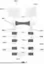


Sources:
- United States Patent and Trademark Office - verify current appl. status at the USPTO↗
Recent applications in this class:
- » 20250198696 2025-06-19
LIQUEFIED NATURAL GAS PRODUCTION FACILITY ON GRAVITY-BASED STRUCTURES - » 20160356545 2016-12-08
GAS LIQUEFACTION METHOD AND SYSTEM
Recent applications for this Assignee:
- » 20260118021 2026-04-30
ENHANCED MULTI-STAGE DILUTION REFRIGERATOR WITH OPTIMIZED THERMAL EXCHANGE - » 20260029168 2026-01-29
INTEGRATED DILUTION REFRIGERATORS - » 20260029167 2026-01-29
INTEGRATED DILUTION REFRIGERATORS - » 20260022870 2026-01-22
INTEGRATED DILUTION REFRIGERATORS - » 20260009566 2026-01-08
INTEGRATED DILUTION REFRIGERATORS - » 20250230954 2025-07-17
CRYOGENIC SYSTEM INCLUDING INTEGRATED CRYOCOOLER AND DILUTION REFRIGERATOR - » 20240295348 2024-09-05
INTEGRATED DILUTION REFRIGERATORS - » 20240295347 2024-09-05
INTEGRATED DILUTION REFRIGERATORS - » 20230290544 2023-09-14
SYSTEMS AND METHODS FOR MANUFACTURE OF FLEXIBLE SHIELDED RIBBON CABLES - » 20230012324 2023-01-12
Integrated dilution refrigerators