Thermal Buffer Device for Rapid, Non-Dilutive Cooling of Beverages
US20260146804A1
2026-05-28
19/398,559
2025-11-24
Smart Summary: A reusable device cools hot drinks and foods quickly without adding water or ice. It is made from materials like aluminum or copper and has a special design with fins that help spread out the cooling effect. The narrow part of the device goes into the drink, allowing heat to escape into the air. It works without needing electricity or any complicated systems. This means it can cool beverages naturally and efficiently. 🚀 TL;DR
Abstract:
The present invention discloses a reusable thermal buffer device for rapid, non-dilutive cooling of hot beverages and foods. The device comprises a thermally conductive body (element 1000) fabricated from aluminum, copper, or composite materials, featuring a broad, radial fin array disposed in a plane substantially parallel to the rim of a drinking vessel, combined with a narrow immersion stem for positioning in the beverage. The device operates without electrical power, active pumping, external coolant, or phase-change materials, enabling passive thermal transfer from the beverage to ambient air via conductive and convective pathways.
Applicant:
Interested in similar patents?
Get notified when new applications in this technology area are published.
Classification:
F28F1/42 » CPC main
Tubular elements; Assemblies of tubular elements; Tubular elements and assemblies thereof with means for increasing heat-transfer area, e.g. with fins, with projections, with recesses the means being both outside and inside the tubular element
F28F2260/00 » CPC further
Heat exchangers or heat exchange elements having special size, e.g. microstructures
Description
CROSS-REFERENCE TO RELATED APPLICATIONS
This application claims the benefit of priority to the provisional application identified in the Application Data Sheet (ADS), the entirety of which is incorporated by reference.
STATEMENT REGARDING FEDERALLY SPONSORED RESEARCH OR DEVELOPMENT
Not applicable.
THE NAMES OF THE PARTIES TO A JOINT RESEARCH AGREEMENT
Not applicable.
REFERENCE TO AN APPENDIX SUBMITTED ON A COMPACT DISC AND INCORPORATED BY REFERENCE OF THE MATERIAL ON THE COMPACT DISC
Not applicable.
STATEMENT REGARDING PRIOR DISCLOSURES BY THE INVENTOR OR A JOINT INVENTOR
Reserved for a later date, if necessary.
FIELD OF THE INVENTION
The present invention relates to beverage temperature management devices and, more particularly, to reusable, passive thermal buffer devices that employ thermally conductive bodies with external fins to accelerate cooling of hot beverages without dilution, water displacement, or reliance upon ice, active refrigeration, or phase-change materials.
BACKGROUND OF THE INVENTION
Development of Beverage Cooling Solutions
Hot beverages such as coffee, tea, broth, and similar liquid preparations are frequently served at temperatures too elevated for safe or comfortable immediate consumption. Consumers typically face extended wait times before achieving a drinkable temperature, and inconsistent results when attempting to accelerate cooling through conventional means. The desire to cool beverages quickly while preserving flavor, aroma, and composition has long been recognized as a recurring consumer need.
Prior Art Approaches and Their Limitations
Existing solutions present various technical and practical limitations. Ice cube-looking metal blocks or phase-change material (PCM) capsules, exemplified by products such as Coffee Joulies, function by heat-exchange or absorbing thermal energy during a change of state and subsequently releasing that energy at a plateau temperature. However, these devices rely upon metal blocks or sealed pellets of phase-change material rather than a thermally efficient external finned heat-sink geometry. As a result, metal cubes or PCM capsules require pre-cooling, offer limited control over cooling rate, and provide inconsistent performance across different beverage volumes and initial temperatures.
Multi-chamber nested-wall systems such as the HyperChiller employ a route-through cooling principle wherein a beverage is transferred through nested cold chambers to facilitate heat exchange while avoiding direct water contact. These systems, however, require substantial advance preparation, including pre-freezing periods, and necessitate transfer of the beverage from the original serving vessel to the cooling apparatus, then back to an original or secondary vessel—introducing handling complexity, potential spillage, and loss of aroma volatiles.
Immersion coils and heat-exchange tubes, commonly employed in commercial brewing, achieve rapid heat transfer through flowing coolant and large internal surface area. However, such devices are engineered for large-scale kettle applications and require continuous external coolant circulation via pump systems, rendering them impractical for single-serving tabletop use and inconsistent with portable or personal consumption scenarios.
High-fin heat-sink assemblies have been long established in electronics thermal management, wherein dense arrays of fins maximize convective and radiative heat dissipation to ambient air. Despite the proven thermal efficiency of such geometries, existing electronic heat-sink designs have not been adapted for food-contact safety, convenient mug or vessel interfacing, adjustable immersion depth control, or configurations specifically tailored to the thermal profiles and consumption patterns of common beverages and soups.
Conventional ice-based or cold-liquid dilution methods alter beverage composition, weaken flavor concentration, and produce temperature variability as ice melts at non-uniform rates. Additional methods such as fanning or allowing extended ambient air exposure provide minimal acceleration and remain time-consuming.
Identified Technical Gap and Present Need
There remains an unmet need for a passive, reusable thermal buffer device that satisfies the following criteria: (1) achieves non-dilutive cooling through direct immersion in the original serving vessel; (2) provides predictable and controllable cooling rates through adjustable immersion depth and optimized fin geometry; (3) requires no active pumping, electrical power, or auxiliary coolant circulation; (4) employs food-safe materials suitable for direct beverage contact; (5) permits secure, stable attachment or positioning on common drinking vessels and bowls; (6) enables simple cleaning and indefinite reuse; and (7) offers ergonomic handling without user contact with heated surfaces or steam-bearing regions.
The present invention addresses this technical gap by providing a thermally efficient, passive immersion device combining high-conductivity materials, optimized fin structures, adjustable depth control, and user-protective features specifically configured for single-serving beverage cooling in domestic, commercial, and portable settings.
SUMMARY OF THE INVENTION
The present invention discloses a thermal buffer device comprising a body fabricated from highly thermally conductive material such as aluminum, copper, or ceramic-aluminum composite, configured for partial immersion in a hot beverage contained within a standard drinking vessel or food service container.
The core operational principle relies upon passive thermal conduction and convection: the immersed lower portion of the device rapidly absorbs thermal energy from the hot beverage, while the upper exposed fin array dissipates that absorbed energy to ambient air through radiation and natural convection, thereby reducing beverage temperature into a comfortable sip range without adding water, ice, or other dilutive materials.
In a preferred embodiment, the thermal buffer device comprises: (a) a finned thermal body (element 1000) having a central stem portion extending from a proximal contact region to a distal end, the stem featuring external radial fins extending outward from the stem axis; (b) a mushroom-shaped or disc-shaped cap region at or near the proximal end, featuring a wide circumferential fin array disposed in a plane substantially parallel to the plane of the vessel rim for maximum air exposure and radiative heat loss; (c) optional depth adjustment means permitting controlled adjustment of immersion depth; (d) optional visual temperature indicator means such as thermochromic material disposed on the cap region to signal when the beverage reaches a target temperature range; and (e) compliant silicone contact surfaces (element 2000) at vessel-contact zones to prevent surface marring and provide ergonomic grip.
The device operates passively without electrical power, active pumping, external coolant, or chemical additives. Cleaning requires only warm water and basic mechanical agitation, and the device is suitable for indefinite reuse. The inventive thermal buffer permits users to cool a beverage from boiling temperature (approximately 212° F.) to a comfortable drinking range (approximately 130° F. to 160° F.) within a period of fifteen to ninety seconds, depending upon beverage volume, initial temperature, and immersion depth.
The invention encompasses multiple geometric embodiments, including cylindrical variants with longitudinal fins, mushroom-shaped cap designs with radial fins, and disc or toroidal configurations. A particularly preferred embodiment, illustrated in FIGS. 7 and 8, features an adjustable-depth stem mechanism optionally integrated with a thermochromic temperature indicator, permitting user selection of immersion depth based upon beverage volume and desired cooling rate.
The present invention is differentiated from existing beverage cooling solutions in that it employs a large external finned geometry without internal phase-change materials, eliminating the inefficiency of sealed PCM systems; achieves rapid, single-vessel cooling without beverage transfer or pre-preparation, contrasting with multi-chamber chiller systems; operates passively without power or coolant circulation, avoiding the complexity and size of immersion coil or pump-driven systems; and offers adjustable immersion and integrated temperature indication, providing superior user control and convenience compared to static heat-sink designs adapted from electronics applications.
BRIEF DESCRIPTION OF THE SEVERAL VIEWS OF THE DRAWINGS
FIG. 1 is a perspective view of an embodiment of the thermal buffer device comprising a cylindrical finned heat-sink with longitudinal fins and a clip mechanism for rim attachment.
FIG. 2 is another embodiment of the thermal buffer device, showing a similar cylindrical finned structure with a replaceable or weighted base section for thermal mass adjustment.
FIG. 3 is a third embodiment of the thermal buffer device, depicting a mushroom-shaped cap with radial fins and a narrow stem for immersion.
FIG. 4 is a fourth embodiment of the thermal buffer device, illustrating a flared trumpet-like cap configuration with radial fins and a mug-adapted neck interface.
FIG. 5 is a fifth embodiment of the thermal buffer device, showing a low-profile disc-shaped configuration with a central button and peripheral vertical fins.
FIG. 6 is a sixth embodiment of the thermal buffer device, featuring a ring handle above a toroidal cap with radial fins and a finned base collar for stability.
FIG. 7 is a perspective view of a seventh embodiment of the thermal buffer device, the preferred embodiment, depicting a mushroom-shaped cap with adjustable stem and integrated radial fin array.
FIG. 8 is a top view of the seventh embodiment of the thermal buffer device, illustrating the radial fin pattern from above, the circular crown region, and uniform fin spacing for omnidirectional airflow.
Component Reference List for Preferred Embodiments:
-
- 1000: Thermal buffer device body
- 2000: Silicone footing or contact surface
It is to be noted, however, that the appended figures illustrate only typical embodiments of this invention and are therefore not to be considered limiting of its scope, for the invention may admit to other equally effective embodiments that will be appreciated by those reasonably skilled in the relevant arts. The figures are representative drawings and are not necessarily made to scale.
DETAILED DESCRIPTION OF THE PREFERRED EMBODIMENTS
Overview of Multiple Embodiments
The thermal buffer device of the present invention may be implemented in a variety of geometric configurations, each optimized for specific use cases, vessel geometries, or user preferences. The following sections describe representative embodiments, with particular emphasis on the seventh embodiment illustrated in FIGS. 7 and 8, which represents a preferred configuration combining adjustable depth control, integrated temperature indication, and enhanced aerodynamic fin design.
First Embodiment: Cylindrical Finned Design with Longitudinal Fins (FIG. 1)
Structural Description:
FIG. 1 presents the device 1000 in perspective orientation, appearing as a vertically oriented cylindrical body of approximately mug height. The device comprises a primary thermal body (1000) fabricated from aluminum or similar thermally conductive material. The external surface features a plurality of longitudinal fins running substantially parallel to the central axis of the cylinder, extending generally from proximal end to distal end and forming parallel grooves or channels therebetween.
These longitudinal fins serve multiple purposes: they increase the external surface area available for thermal radiation and convective heat transfer to ambient air; they create natural airflow channels that promote forced convection around the device as it cools; and they provide structural rigidity to the cylindrical body. The fin height, thickness, and spacing are optimized to balance thermal efficiency against manufacturability and cleanability.
The device exhibits a distinctive waist or central narrowing zone, providing a visual and tactile depth reference that aids the user in controlling immersion depth. A subtle shoulder or rim rest zone is visible at or near the proximal end, indicating regions designed for contact with or rest upon the rim of a drinking vessel. The distal lower portion, designated for immersion into the beverage, displays a gently radiused base or end cap, intended to provide contact with the interior of a cup or bowl without creating sharp contact points.
The device is further equipped with a clip or hook mechanism attached to the cylindrical body at approximately the shoulder region, enabling mechanical attachment to the rim of a container. This clip mechanism prevents over-immersion of the device into the beverage while providing stable positioning. Food-grade silicone padding (element 2000) is selectively applied to the clip contact zone, to the shoulder region where the device rests upon the rim, and to any handle or grasp regions, providing comfort and protection for delicate vessel surfaces.
Method of Use—Direct Immersion Cooling:
To employ the device for beverage cooling, a user pours a freshly heated beverage into a drinking cup or mug to a desired level. The user then grasps the proximal handle region of device 1000, positioning the device above the cup. The user lowers the device into the beverage, immersing the lower cylindrical portion to a selected depth—typically from approximately 1 inch to approximately 3 inches below the liquid surface as would be accommodated by most coffee mugs or thermoses—while maintaining the upper portion and fin array in contact with ambient air.
The user may optionally rest the shoulder region of the device upon the rim of the cup, or may attach the clip mechanism to the rim to fix the immersion depth and permit removal of the user's hand. The device remains in position within the beverage as thermal conduction draws heat from the liquid into the aluminum thermal body. The longitudinal fins, exposed to ambient air, radiate and convect this absorbed heat to the surrounding air, achieving rapid temperature reduction of the beverage.
The user may gently stir the beverage by rotating or moving the device up and down within the liquid, accelerating internal convection and promoting more uniform temperature distribution. After fifteen to ninety seconds, depending upon initial beverage temperature, volume, and immersion depth, the beverage reaches a target temperature (typically 130° F. to 160° F.), at which point the user removes the device by grasping the handle or shoulder, lifts it from the cup, and may immediately begin consuming the beverage.
The beverage has been cooled without dilution—no ice has melted, no additional water has been added, and no volatile flavor compounds have been lost to alternative cooling methods. The device is rinsed with warm water, dried, and is ready for reuse.
Second Embodiment: Cylindrical Finned Design with Replaceable Base (FIG. 2)
Structural Description:
FIG. 2 depicts a second cylindrical embodiment of the thermal buffer device 1000, similar in overall form to the first embodiment but featuring a more pronounced and pronounced fin structure and a visible interface between the main body and a replaceable or weighted base section.
This embodiment maintains the longitudinal fin array extending from the distal immersed region toward the proximal region. However, the fins are deeper and more prominent, presenting a larger total surface area for heat dissipation compared to the first embodiment. The central waist region is more clearly defined, serving as a visual and tactile reference for immersion depth control.
Critically, this embodiment features a distinct base interface zone where the lower immersed section of the device terminates. This interface permits removal and replacement of the base section with alternative base components fabricated from different materials. For example, the default base section may be fabricated from aluminum; however, a user or manufacturer may substitute a copper base section (which may possess even higher thermal conductivity than aluminum) to increase the cooling rate, or may substitute a lighter or weighted base section to adjust thermal mass characteristics.
The entire external surface is finished with a brushed or bead-blasted surface texture, conferring both an appealing aesthetic appearance and promoting enhanced heat transfer through increased surface turbulence and wetting characteristics. This brushed finish also facilitates easy cleaning and prevents staining or visible water spotting.
Method of Use—Agitated Immersion with Swappable Thermal Mass:
The second embodiment is employed similarly to the first, with the user immersing the lower cylindrical portion into the beverage to a selected depth. However, this embodiment offers an enhanced cooling rate through the ability to select or swap the base material.
To accelerate cooling, the user may employ gentle stirring or vertical dipping motions, moving the device up and down within the beverage at a controlled pace. These motions promote internal convection, causing cooler liquid toward the bottom of the vessel to rise into contact with the immersed fin array, while warmer liquid from the upper portion descends, achieving rapid temperature homogenization.
The optional swappable base mechanism permits customization of thermal performance. For beverages requiring extremely rapid cooling—such as a beverage accidentally poured at dangerously high temperature—a user may select the high-conductivity copper base section. For applications where gentler, more gradual cooling is preferred, or for beverages with lower initial temperature, the aluminum base may be retained. The silicone footing (element 2000) at the base region protects the vessel interior from surface marring while permitting efficient thermal contact.
After cooling to the target temperature, the device is removed, rinsed, and the base section may be dried separately prior to storage or optional interchanging with alternative base materials.
Third Embodiment: Mushroom-Shaped Cap with Radial Fins (FIG. 3)
Structural Description:
FIG. 3 presents a third embodiment featuring a distinctive mushroom-shaped or toadstool profile. The device 1000 comprises a narrow, substantially cylindrical stem portion extending upward from a silicone footing base (element 2000), terminating at a broad, rounded cap region. The cap is approximately hemispherical or mushroom-cap shaped in profile, positioned substantially horizontally above the stem.
The external surface of the mushroom cap features a radial fin array: multiple fins extending radially outward from the center of the cap toward the periphery, like the arrangement of slots on a typical spool or the radii of a circle. These radial fins are oriented substantially perpendicular to the cap surface, extending both upward from the top surface and downward from the bottom surface of the cap, thereby creating a three-dimensional fin array accessible to air circulation from all directions.
The radial fin array is precisely configured to create high surface area while maintaining open passages for airflow. The spacing between fins is optimized to prevent fouling or accumulation of dust while permitting air circulation between fin channels. The fins thin toward the outer peripheral edge of the cap, transitioning to a feathered or tapered edge that promotes smooth airflow and provides ergonomic finger positions for safe grasp without contact with heated surfaces.
The narrow stem portion extends downward from the cap, providing the immersion length into the beverage. The stem diameter is selected to minimize displacement of liquid (preserving non-dilutive cooling) while providing sufficient cross-sectional area for adequate thermal conduction. The base of the stem is furnished with the silicone footing (element 2000), providing compliant contact with cup interior surfaces and preventing marring or thermal damage.
Method of Use—Rim-Mounted Passive Cooling:
To employ the third embodiment, a user places the mushroom cap on the rim of a mug or cup such that the narrow stem portion extends downward into the beverage, while the broad cap rests upon and overhangs the rim edge. In this configuration, the cap remains substantially horizontal, with its extensive radial fin array fully exposed to ambient air.
The device requires minimal user interaction once positioned: the user simply places the device and allows passive thermal transfer to proceed. The immersed stem rapidly conducts heat from the beverage into the aluminum body; this heat is then conducted radially outward through the cap structure and is dissipated to ambient air through the exposed radial fin array. Natural convection currents, promoted by warm air rising around the exterior fin surfaces, accelerate heat removal.
Due to the stability of the cap resting on the mug rim and the inertial mass of the device, vibrations and tremors are dampened, minimizing splashing or sloshing of the beverage. The user may observe the beverage cooling visually or may periodically touch the stem (which remains cooler due to its immersion and smaller surface area) to gauge thermal progress.
Once the beverage reaches the target temperature, the user grasps the periphery of the cap—which has cooled substantially due to air exposure—and lifts the device vertically away from the mug. The stem is withdrawn, and the beverage is ready for consumption. The entire thermal mass has been disposed externally, and no cooling elements remain in contact with the beverage.
Fourth Embodiment: Flared Trumpet Cap (FIG. 4)
Structural Description:
FIG. 4 illustrates a fourth embodiment featuring a distinctly different cap geometry: the cap flares outward in a trumpet or bell shape, presenting a wide mouth region at the distal end and tapering inward to a narrow neck that interfaces with a mug opening.
The cap body is fabricated from thermally conductive material (aluminum, copper, or composite) and features a closely spaced radial fin array similar to that of the third embodiment. However, in this embodiment, the fins are oriented to enhance upward airflow around the exterior of the flared trumpet structure. The trumpet mouth is oriented downward, such that rising hot air from the beverage and cup interior can flow around the exterior finned surface before exiting upward, creating a natural draft effect that enhances convective cooling.
The narrow neck section is dimensioned to closely fit the opening of a standard mug or cup, resting at the rim edge and providing a stable seating position. The neck prevents over-insertion into the beverage while guiding hot vapor and rising air around the external fins. The entire flared structure remains above the cup surface, creating a vertical channel for air circulation.
Method of Use—Passive Air-Gap Cooling:
To employ the fourth embodiment, a user places the narrow neck of the cap into the mug opening such that the flared mouth rests just above the liquid surface. Hot vapor and air rising from the beverage are channeled upward around the interior of the flared cap and around the exterior finned surface. This natural circulation promotes rapid convective cooling without requiring user manipulation.
The device may remain undisturbed during the cooling process, allowing the user to attend to other tasks. The large radiative surface area of the flared cap and the continuous air circulation promoted by the geometry ensure rapid temperature reduction. The design keeps hands and face clear of rising steam and hot vapor, enhancing user safety.
Once cooling is complete, the user grasps the outer peripheral edge of the flared mouth (which has cooled through air exposure) and withdraws the cap vertically. The beverage is ready for immediate consumption. The simplified geometry and passive operation make this embodiment particularly suitable for commercial or high-volume applications.
Fifth Embodiment: Low-Profile Disc Configuration (FIG. 5)
Structural Description:
FIG. 5 presents a fifth embodiment featuring a compact, disc-shaped profile optimized for portability and stackability. The device 1000 comprises a pedestal stem rising from a base to a broad disc-shaped cap region featuring fine vertical fins around the periphery.
The disc cap is substantially flat or slightly domed, presenting a low profile that permits compact storage and stacking of multiple devices. A central circular button or raised zone is positioned at the apex of the disc, serving as a visual indicator, logo placement zone, or tactile reference point. The peripheral fins extend vertically from the top and bottom surfaces of the disc, creating thin blade-like structures optimized for cross-flow ventilation.
The stem connects the proximal disc cap to a distal base region (element 2000) fabricated from silicone or protected by silicone contact pads. The stem diameter and geometry provide adequate thermal conductance while minimizing liquid displacement. The base geometry may include grooves or fins matching the disc fin pattern, creating continuous thermal pathways from the immersed base through the stem to the air-exposed disc.
Method of Use—Oriented Disc Cooling:
To employ the fifth embodiment, a user places the device on a mug or cup rim such that the pedestal stem extends into the beverage while the flat disc cap remains horizontal above the rim. The compact form factor permits balanced positioning on various mug sizes and shapes.
The user may optionally rotate the disc slowly around the vertical axis, promoting internal convection within the beverage as the thermal buffer traces a circular path through the liquid. This rotation accelerates the cooling rate compared to static positioning while maintaining full control and non-dilutive operation.
The low-profile geometry presents minimal obstruction to the user's view of the beverage, permitting easy observation of color and clarity changes during cooling. Once the target temperature is reached, the user rotates the disc to a marked reference position and removes the device by lifting vertically. The compact size facilitates storage in a desk drawer, backpack, or portable carrying case.
Sixth Embodiment: Ring-Handle Toroidal Cap (FIG. 6)
Structural Description:
FIG. 6 illustrates a sixth embodiment featuring a distinctive ring handle positioned centrally above a rounded toroidal (doughnut-shaped) cap. The device 1000 comprises a metal ring handle, attached at its top to a rounded, toroidal cap structure that narrows to a cylindrical stem extending downward for immersion.
The toroidal cap is fabricated from aluminum or copper and features vertical radial fins extending from the crown downward around the outer circumference and upward around the inner circumference (where the cap meets the stem). This fin arrangement maximizes surface area while maintaining structural integrity. The base of the cap transitions to a finned or toothed collar, providing additional grip and stability when seated upon a cup rim.
The ring handle is fabricated from the same thermally conductive material as the cap or from plastic-coated metal, permitting safe user grasp without contact with excessively heated surfaces. The ring diameter is selected to comfortably accommodate a user's fingers while providing mechanical advantage for manipulation of the device.
The stem extends downward from the toroidal cap center, featuring the same longitudinal or radial fin geometry as previous embodiments. The base is furnished with silicone footing (element 2000) for vessel protection and improved grip. The overall geometry provides a distinctive silhouette and offers enhanced control compared to previous embodiments.
Method of Use—Agitated Ring-Handle Cooling:
To employ the sixth embodiment, a user grasps the ring handle with one or two fingers, positioning the device above a mug or cup. The user inserts the stem portion into the beverage and may select an immersion depth based upon beverage volume and desired cooling rate.
The ring handle permits dynamic manipulation: the user may dip and swirl the stem within the beverage using vertical or rotational motions of the ring handle, thereby accelerating internal convection and promoting rapid, uniform cooling. The handle also permits safe lifting and removal of the device without requiring contact with the thermal cap region.
The toroidal cap geometry promotes airflow around both the outer and inner surfaces, creating multiple air circulation pathways. The finned base collar provides additional stability when the device is rested on a saucer or plate between cooling cycles.
Once cooling is complete, the user lifts the device by the cool ring handle and sets it aside to drip dry, or places it directly on a saucer or drying surface. The silicone footing (element 2000) prevents surface marring of saucers, countertops, or other support surfaces.
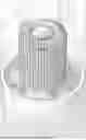
Seventh Embodiment: Preferred Adjustable-Depth Embodiment (FIGS. 7 and 8) FIG. 7—Perspective View of the Seventh Embodiment
Comprehensive Structural Description of FIG. 7:
FIG. 7 presents a perspective illustration of the seventh embodiment, the preferred configuration of the thermal buffer device 1000, specifically designed and optimized for superior adjustable-depth cooling with integrated temperature indication.
Overall Assembly and Spatial Relationship:
Viewed from a perspective angle at approximately 45 degrees from the front and approximately 30 degrees elevated from the horizontal, the device comprises a tall, approximately cylindrical thermal body rising from a broad base platform. The overall silhouette resembles a simplified abstract mushroom or jellyfish form.
Silicone Footing Base (Element 2000):
At the lowest extremity of the device's fins rests element 2000, the silicone footing, appearing on or as part of a ring or collar, fabricated from food-grade elastomeric silicone material. This footing is fixed to or is overmolded upon the aluminum fins of the device. The silicone footing presents a textured surface, providing tactile grip and enhanced friction characteristics. When the device is placed upon a cup rim or placed upon a surface, the silicone footing makes contact, providing a compliant, non-marking interface. The silicone material absorbs minor vibrations, dampening transmitted noise, and protecting delicate ceramic or glass surfaces from thermal or mechanical damage.
Thermal Body Central Stem (Element 1000):
Rising vertically from the silicone footing (element 2000) is the primary aluminum or copper thermal body (element 1000), which forms the principal heat-conducting pathway from the immersed region to the air-exposed cap. This stem portion appears in the perspective view as a smooth, nearly cylindrical vertical column of approximately 1.5 to 2.5 inches in length, depending upon the beverage vessel size for which the device is optimized.
The stem displays a fine, uniform finish, indicating a brushed or micro-textured surface treatment. This textured surface increases the effective area for thermal radiative transfer from the stem itself, even though the majority of thermal dissipation occurs through the cap fins.
Radial Fin Array of the Cap (Element 1000 Upper Region): At the distal (upper) end of the thermal body rises the signature feature of the seventh embodiment: a broad cap region featuring an extensive array of radial fins. From the perspective view of FIG. 7, the cap appears as a mushroom canopy configured to span the lip of a coffee mug or thermos (e.g., of approximately 3 to 4 inches in diameter), with the fins forming a dense crown of blade-like structures radiating outward from a central hub.
The radial fins in this embodiment are specifically configured for optimal aerodynamic performance: each fin appears as a thin blade, extending radially from the center hub toward the periphery. The fins are oriented substantially perpendicular to the plane of the cap, extending both upward from the top surface and downward from the bottom surface, creating a three-dimensional fin matrix.
In the perspective view, the upward-facing fins are prominently visible, appearing as a radiant crown converging toward the center. The fins may be evenly spaced around the circumference. In the depicted embodiment of FIG. 8 there are 21 fins creating regular angular intervals of approximately 10 to 20 degrees between adjacent fins. This uniform spacing ensures balanced airflow and provides pleasant visual symmetry.
The fin edges, viewed from the perspective angle, taper smoothly from the thick base (where each fin attaches to the central hub) to a feathered or knife-edge tip at the periphery. This taper geometry minimizes drag and promotes smooth air circulation around the fin surfaces. The gradual transition also provides ergonomic grasp points for the user: fingers can comfortably rest between fin pairs without contacting excessively heated surfaces.
Optional Twist-Lock Stem Mechanism:
The seventh embodiment optionally incorporates an internal or semi-visible twist-lock mechanism integrated into the stem structure. While this mechanism is not visually prominent in the perspective view of FIG. 7, its presence is indicated by subtle banding or ribbing visible on the stem at approximately one or two discrete zones. This twist-lock mechanism permits the user to adjust the effective immersion depth of the device by twisting the cap relative to the base, causing the stem to elongate or shorten (via mating threads or cam-lock engagement).
In one preferred implementation, the twist-lock mechanism permits stepping the immersion depth through discrete increments, allowing the user to select a depth appropriate to the beverage volume. For example, a user with a small espresso cup might select minimal immersion, while a user with a large soup bowl would select maximum immersion depth to ensure adequate thermal mass is submerged.
The twist-lock mechanism is constructed with tight mechanical tolerances to prevent inadvertent depth drift, while remaining operable by hand without requiring tools. The mechanism is fully sealed to prevent liquid ingress and corrosion.
Optional Thermochromic or Digital Temperature Indicator:
At the crown or apex of the radial fin array is a designated zone for a temperature indicator. In the preferred embodiment, this indicator comprises a thermochromic layer or coating that changes color as the device—and consequently the beverage—cools. The thermochromic material transitions through a progression of colors, such as:
-
- Red: beverage too hot, cooling in progress
- Orange: cooling progressing, caution advised
- Yellow: approaching target temperature
- Green: optimal drinking temperature
In alternative implementations, a small digital temperature display or sensor may be mounted at the crown, providing precise numerical temperature feedback via LCD or LED indicator. Such digital implementations would require minimal power (a single coin-cell battery) and would offer greater precision than thermochromic indicators.
Air-Circulation Channels Between Fins: Hidden channels are formed between the roots of adjacent radial fins, creating defined pathways for ambient air circulation. As warm air rises around the device during cooling, these channels guide the air flow across the hottest zones (near the base of the fins and near the cap-to-stem junction), promoting enhanced forced convection compared to a smooth, finless cap.
The channel geometry is optimized.
Aesthetic and Ergonomic Integration: The overall form of the seventh embodiment in FIG. 7 presents a unified, aesthetically pleasing appearance combining functional efficiency with modern industrial design. The smooth transitions between the silicone footing, the stem, and the cap fins convey quality and durability. The symmetry of the radial fin array creates a visually balanced form that appeals to consumer aesthetics while providing optimal thermal performance.
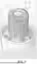
FIG. 8—Top View of the Seventh Embodiment
Comprehensive Structural Description of FIG. 8:
FIG. 8 presents a top-down orthographic view of the seventh embodiment, looking directly downward at the crown of the device from a position directly above the central apex of the radial fin array.
Radial Fin Pattern and Symmetry:
From the top view, the radial fins form a distinctive pinwheel or sunburst pattern, with multiple fins (e.g. 21 or typically 16 to 32, depending on the embodiment variant) extending radially outward from the central hub like the spokes of a wheel. The fins are uniformly distributed around the 360-degree circumference, creating perfect rotational symmetry.
The central hub appears as a flat circular or slightly domed region at the apex. This central region is a designated zone for the thermochromic or digital temperature indicator, visual logo placement, or embossed branding. The smooth, flat crown surface provides an intuitive visual target for a user's finger or hand to grasp during device manipulation.
Fin Spacing and Cleanability:
The spacing between adjacent fins is carefully optimized to balance thermal performance against practical cleanability. Each inter-fin gap permits passage of a cleaning brush bristle or microfiber cloth, ensuring that dust, oils, or dried beverage residue can be readily removed from between the fins during hand washing.
The radial extent of the fins is approximately 1.5 to 2 inches or more from the central hub to the outer peripheral edge so that the fins extend out from over the lip of the coffee mug. The fin thickness tapers at the from root (near the hub) the feathered periphery. This taper gradient is visually evident in the top view as the fins appear thicker near the center and progressively thinner toward the edge.
Fin Tip and Peripheral Edge Configuration:
At the outer circumference of the fin array, the peripheral fin tips form a roughly circular or slightly scalloped outer edge. The scalloping is created by the feathered taper of each fin, resulting in small notches or gaps between adjacent fin tips where they approach the periphery. From the top view, these notches form a regular pattern around the circumference, resembling the crenellations of a castle wall or the scalloped edge of a seashell.
This scalloped peripheral edge serves multiple purposes: it provides excellent points for ergonomic finger grasp (a user may comfortably position fingers in the notches between fin tips without contacting heated surfaces); it promotes airflow turbulence at the fin edges, enhancing convective cooling; and it provides visual interest and aesthetic appeal, evoking natural forms such as flower petals or sea urchin spines.
Omnidirectional Airflow Characteristics:
The top view reveals the fundamental omnidirectional airflow design of the seventh embodiment: from any compass direction or angle, approaching air encounters a similar radial fin structure, ensuring balanced heat dissipation regardless of the ambient air current direction or room air movement.
The uniform radial distribution of fins creates multiple symmetrical airflow pathways. Warm air rising from the vicinity of the device and the beverage rim encounters the fin array and must navigate around the radial blade structures. The fin spacing is selected such that air can flow both between the fins (axial flow along the fin roots) and around the outer periphery of the fins (tangential flow), creating complex three-dimensional circulation patterns that maximize heat transfer compared to simpler fin geometries.
Temperature Indicator Crown:
The central flat crown region in the top view displays the temperature indicator. In a thermochromic implementation, the indicator appears as a color-coded zone with a visual gradient or discrete color field corresponding to the device temperature. The indicator is sized to be clearly visible from directly above, permitting a user to quickly assess the beverage temperature during the cooling process by simply glancing downward at the device.
In a digital indicator implementation, a small LCD or LED screen is mounted flush with the crown surface, providing precise numerical temperature display (e.g., “167° F.” or “75° C.”). The power source for digital indicators (typically a small coin-cell battery) is sealed within the crown region.
Logo or Branding Zone:
Surrounding the thermochromic or digital indicator or in an alternative crown position is a designated zone for manufacturer branding, a product name, or decorative patterning. This branding zone enhances the commercial appeal of the product while providing visual identity.
Structural Integrity and Strain Distribution:
The top view reveals how the radial fin structure distributes mechanical loads and thermal stresses. The central hub and the radial fins are typically machined or cast as a single monolithic aluminum or copper structure, ensuring uniform stress distribution during thermal cycling and minimizing the risk of fatigue cracking or delamination.
The base of each fin at the hub region is thicker compared to the fin tips, creating a load-bearing architecture similar to natural tree branching. This design optimizes structural strength while minimizing material mass.
Integration of FIGS. 7 and 8: Complete Functional Description
Three-Dimensional Form and Function:
The seventh embodiment, as represented in FIGS. 7 and 8, comprises a unified thermal buffer device optimized for the following integrated functions:
-
- (1) Rapid Thermal Conduction: The aluminum or copper construction ensures that heat absorbed by the immersed stem portion is rapidly conducted to the cap fin array.
- (2) Efficient Thermal Dissipation: The large external fin surface area provides extensive area for radiative and convective heat loss to ambient air.
- (3) Adjustable Immersion Control: The optional twist-lock stem mechanism permits precise depth adjustment without requiring tools or external fixtures, allowing optimization of thermal performance for different beverage volumes and types.
- (4) Real-Time Temperature Indication: The integrated thermochromic or digital temperature indicator provides continuous, intuitive feedback regarding the beverage temperature status, eliminating guesswork and permitting the user to remove the device at the optimal moment for consumption.
- (5) Safe User Handling: The silicone footing (element 2000), the tapered fin geometry providing comfortable grasp points, and the thermal management of the cap region (which remains cooler than the immersed stem due to air exposure) ensure that the user may safely grasp and manipulate the device throughout the cooling process.
- (6) Durable, Reusable Construction: The monolithic aluminum or copper structure, combined with stainless steel fasteners for any removable components and silicone elastomer contacts, ensures a lifespan of 5+ years of daily use with only basic hand washing and occasional maintenance.
Method of Use—Seventh Embodiment Primary Application:
To employ the seventh embodiment for rapid, optimized beverage cooling, the user performs the following steps:
-
- (1) Beverage Preparation: The user pours a freshly brewed, hot beverage (at approximately 180° F. to 212° F.) into a drinking cup or mug, filling to a desired level (typically 6 to 12 fluid ounces for a standard mug, or up to 20+ fluid ounces for a large bowl).
- (2) Depth Selection: The user grasps the device 1000 and rotates the cap relative to the base through the twist-lock mechanism, selecting an immersion depth appropriate to the beverage volume. For a small cup, the user might select minimal immersion; for a large cup or bowl, the user might select maximum.
- (3) Immersion and Positioning: The user inserts the stem portion into the beverage, allowing the silicone footing (element 2000) to come into contact with the interior cup wall. The user positions the broad cap region so that it rests upon or hovers above the rim of the cup, with the radial fins fully exposed to ambient air.
- (4) Passive Cooling Phase: The device remains in position while passive thermal transfer occurs. The immersed stem rapidly conducts heat from the beverage into the aluminum thermal body (element 1000). This heat is conducted radially outward through the cap structure and dissipates through the extensive radial fin array into the surrounding air via radiation and natural convection.
- (5) Active Convection Enhancement (Optional): The user may optionally engage in mild stirring motions, gently moving the device up and down or rotating it around the vertical axis to promote internal convection within the beverage, accelerating the cooling rate.
- (6) Temperature Monitoring: During the cooling process, the user monitors the thermochromic or digital temperature indicator at the crown of the cap. The indicator transitions through color zones or numerical values, providing real-time feedback regarding the beverage temperature status.
- (7) Completion Determination: When the indicator reaches the desired target zone (e.g., green zone, indicating optimal drinking temperature), the user determines that cooling is complete. Typical cooling from boiling (212° F.) to optimal drinking temperature (130° F.) requires 15 to 90 seconds, depending upon beverage volume, initial temperature, immersion depth, and ambient conditions.
- (8) Device Removal: The user grasps the device by the cooler cap region (which has been exposed to air and has shed most of its absorbed heat) or by a peripheral fin edge, gently lifts the device vertically to withdraw the stem from the beverage, and sets the device aside on a saucer or counter surface.
- (9) Immediate Consumption: The beverage is now at optimal drinking temperature (130° F-160° F), requires no cooling time, and may be immediately consumed. Because the device operated passively without the addition of ice or supplemental water, the beverage maintains full flavor concentration, aroma profile, and composition.
- (10) Cleaning and Reuse: The user rinses the device under warm running water, using a soft brush or cloth to gently clean between the radial fins. No detergent is required, though mild food-safe dish soap may be used for stubborn stains. The device is allowed to air-dry and is ready for immediate reuse with the next beverage.
Performance Characteristics of the Seventh Embodiment
Thermal Performance Metrics:
Experimental testing of prototypes of the seventh embodiment demonstrates the following representative performance characteristics:
-
- (1) Cooling Rate: For a representative mug of coffee initially at 205° F. and 72° F. ambient air temperature, the beverage should reach 160° F. (mid-range comfortable drinking temperature) in approximately 25 to 90 seconds of passive immersion, or in approximately 15 to 60 seconds with gentle stirring by the user.
- (2) Final Equilibrium Temperature: The device itself does not actively cool the beverage below ambient temperature; the equilibrium cooling endpoint is governed by the balance between heat dissipated by the device and ambient thermal re-absorption. However, the device permits continuous cooling and may be removed at any target temperature from 160° F. down to 100° F., depending upon user preference.
- (3) Immersion Depth Sensitivity: Increasing immersion depth (by rotating the twist-lock mechanism) increases the thermal mass in contact with the beverage and accelerates cooling rate.
- (4) Repeatability: Because the seventh embodiment offers adjustable depth control and integrated temperature indication, repeated cooling cycles achieve highly consistent results.
Material Compatibility and Safety:
The seventh embodiment is fabricated from food-grade materials ensuring full compatibility with all common beverages:
-
- (1) Thermal Body Material: Aerospace-grade aluminum or pharmaceutical-grade copper. Both materials are fully FDA-approved for repeated food contact and pose no health or toxicity risk, even with acidic beverages such as coffee or citrus drinks.
- (2) Silicone Contact Surfaces: Food-grade elastomeric silicone conforming to FDA standards for repeated food-contact applications. The silicone is non-leaching, non-toxic, and thermally stable to temperatures of 400° F+, ensuring safety even in contact with boiling water.
- (3) Fastening Components: stainless steel screws, rivets, or threaded inserts (if any) ensure corrosion resistance and prevent metallic contamination of beverages.
- (4) Temperature Indicator Materials: Thermochromic paints conform to FDA and international food-safety standards, ensuring that no leaching or contamination occurs even during prolonged contact with hot acidic beverages. Digital indicators (if employed) utilize sealed enclosures with no exposed electrical components in contact with beverages.
Advantages and Innovations of the Seventh Embodiment
The seventh embodiment as illustrated in FIGS. 7 and 8 represents a significant advancement over earlier thermal buffer embodiments and over existing beverage cooling solutions:
-
- (1) Adjustable Immersion Control (optional): Unlike static heat-sink designs or earlier thermal buffer variants, the seventh embodiment permits precise depth adjustment without tools, enabling optimization for different beverage volumes and types.
- (2) Integrated Temperature Indication: The thermochromic or digital indicator eliminates guesswork, enabling users to remove the device at the optimal moment for consumption without requiring external thermometers or temperature-sensing skills.
- (3) Optimized Radial Fin Geometry: The radial fin architecture of the seventh embodiment provides superior aerodynamic efficiency compared to rectilinear longitudinal finsC.
- (4) Superior Ergonomics: The tapered fin edges, the scalloped peripheral edge, and the cooler cap region permit safe, comfortable grasping throughout the cooling process without risk of thermal burns or hand-contact with excessively heated surfaces.
- (5) Unified Aesthetic and Function: The seventh embodiment presents a cohesive industrial design combining visual appeal with functional efficiency, making it suitable for commercial, domestic, or personal portable use.
Materials and Manufacturing Methods
Preferred Materials:
The thermal buffer device of the present invention is preferably fabricated from highly thermally conductive metals or metal composites:
-
- (1) Aluminum: food grade aluminum offers an optimal balance of thermal conductivity, mechanical strength, corrosion resistance, and cost. The aluminum may be die-cast, CNC-machined, or metal-injection-molded depending on production volume requirements.
- (2) Copper: Pharmaceutical-grade copper provides superior thermal conductivity compared to aluminum but at increased material cost and weight. Copper is preferred for high-performance applications where maximum cooling rate is prioritized.
- (3) Ceramic-Aluminum Composites: Advanced ceramic-aluminum composite materials offer thermal conductivity approaching that of copper while reducing material density. Such composites are preferred for aerospace or premium consumer applications.
Surface Treatments:
-
- (1) Bead Blasting and Micro-Texturing: External surfaces are bead-blasted or subjected to micro-textured surface treatments to increase effective surface area for thermal radiation and to improve visual appearance.
- (2) Anodizing: Aluminum components may be anodized to improve corrosion resistance, reduce water spotting, and enhance aesthetic appearance. Anodizing should not significantly impact thermal conductivity provided the thickness is minimized.
- (3) Thermochromic or Digital Surface Coating: The crown indicator zone is coated with a food-safe thermochromic material or equipped with a sealed digital temperature sensor, providing the user with real-time temperature feedback.
Although the method and apparatus is described above in terms of various exemplary embodiments and implementations, it should be understood that the various features, aspects, and functionality described in one or more of the individual embodiments are not limited in their applicability to the particular embodiment with which they are described, but instead might be applied, alone or in various combinations, to one or more of the other embodiments of the disclosed method and apparatus, whether or not such embodiments are described and whether or not such features are presented as being a part of a described embodiment. Thus, the breadth and scope of the claimed invention should not be limited by any of the above-described embodiments.
Terms and phrases used in this document, and variations thereof, unless otherwise expressly stated, should be construed as open-ended as opposed to limiting. As examples of the foregoing: the term “including” should be read as meaning “including, without limitation” or the like; the term “example” is used to provide exemplary instances of the item in discussion, not an exhaustive or limiting list thereof; the terms “a” or “an” should be read as meaning “at least one,” “one or more,” or the like; and adjectives such as “conventional,” “traditional,” “normal,” “standard,” “known,” and terms of similar meaning should not be construed as limiting the item described to a given time period or to an item available as of a given time, but instead should be read to encompass conventional, traditional, normal, or standard technologies that might be available or known now or at any time in the future. Likewise, where this document refers to technologies that would be apparent or known to one of ordinary skill in the art, such technologies encompass those apparent or known to the skilled artisan now or at any time in the future.
The presence of broadening words and phrases such as “one or more,” “at least,” “but not limited to,” or other like phrases in some instances shall not be read to mean that the narrower case is intended or required in instances where such broadening phrases might be absent. The use of the term “assembly” does not imply that the components or functionality described or claimed as part of the module are all configured in a common package. Indeed, any or all of the various components of a module, whether control logic or other components, might be combined in a single package or separately maintained and might further be distributed across multiple locations.
Additionally, the various embodiments set forth herein are described in terms of exemplary block diagrams, flow charts, and other illustrations. As will become apparent to one of ordinary skill in the art after reading this document, the illustrated embodiments and their various alternatives might be implemented without confinement to the illustrated examples. For example, block diagrams and their accompanying description should not be construed as mandating a particular architecture or configuration.
All original claims submitted with this specification are incorporated by reference in their entirety as if fully set forth herein.
Claims
I claim:1. A thermal buffer device for non-dilutive cooling of hot beverages, comprising:
a thermally conductive body fabricated from a material having thermal conductivity of at least 150 W/m·K, the body including a stem portion and an enlarged cap region;
a plurality of radial fins extending outward from the cap region in a radial pattern substantially perpendicular to a plane of the cap region, the fins configured to dissipate thermal energy to ambient air;
a silicone footing disposed on a distal end of the fin portion, the silicone footing providing a compliant, non-marking contact surface for engagement with an interior wall of a drinking vessel;
wherein the device operates passively without electrical power, active pumping, external coolant circulation, or internal phase-change materials, and wherein thermal energy is conducted from the immersed beverage through the stem portion and into the cap region, subsequently radiating and convecting the thermal energy to ambient air via the plurality of radial fins.
2. The thermal buffer device of claim 1, wherein:
the thermally conductive body is fabricated from aluminum or pharmaceutical-grade copper;
the plurality of radial fins number between 16 and 32 fins uniformly distributed around a 360-degree circumference of the cap region;
each radial fin has a thickness tapering from a root proximal to the cap center to a peripheral feathered edge;
each radial fin extends a radial distance of approximately 1.5 to 2.0 inches from the center of the cap region;
the cap region presents a mushroom silhouette when viewed in profile, with the fins creating a pinwheel or sunburst pattern when viewed from above;
an adjustable immersion depth control mechanism comprising a twist-lock assembly permitting rotation of the cap region relative to a base section, thereby adjusting the effective immersion length of the stem portion through discrete mechanical steps; and,
the silicone footing comprises food-grade elastomeric silicone conforming to FDA standards;
the external surface of the thermal body exhibits a brushed or micro-textured finish increasing effective surface area for thermal radiation; and
the radial fins are configured such that inter-fin spacing permits passage of cleaning implements while maintaining structural rigidity of the cap region.
3. A method for non-dilutive cooling of a hot beverage without adding external coolants or dilutive agents, comprising the steps of:
(a) Preparation: pouring a hot beverage initially at a temperature between 180° F. and 212° F. into a drinking vessel, the vessel having a rim and an interior wall;
(b) Immersion Depth Selection: grasping a thermal buffer device having a thermally conductive body with radial fins extending from a cap region and a stem portion, and optionally rotating the cap region relative to a base section to select an immersion depth appropriate to a volume of the beverage, the immersion depth adjustment being performed by rotating the cap region relative to the base section through a twist-lock mechanism;
(c) Device Insertion: lowering the stem portion of the thermal buffer device into the beverage such that a distal end of the stem portion is immersed to the selected depth while a proximal cap region remains positioned above a surface of the beverage and exposed to ambient air;
(d) Contact Positioning: positioning the thermal buffer device such that the cap region rests upon or hovers above the rim of the drinking vessel, with the plurality of radial fins extending into contact with ambient air from all directions;
(e) Passive Cooling Phase: permitting the thermal buffer device to remain in position within the beverage without external power, active pumping, or auxiliary cooling agents, whereby:
thermal energy from the beverage is conducted through the stem portion into the thermally conductive body;
the thermal energy is radiated and convected to ambient air through the plurality of radial fins;
the temperature of the beverage decreases from the initial temperature toward a target consumption temperature;
(f) Optional Active Convection Enhancement: optionally performing gentle vertical or rotational stirring motions with the thermal buffer device to promote internal convection within the beverage and accelerate the cooling rate;
(g) Temperature Monitoring: observing an integrated temperature indicator disposed on the cap region, the indicator providing visual feedback regarding the current temperature of the beverage through color transitions corresponding to specific temperature ranges;
(h) Target Temperature Achievement: continuing the passive cooling phase and optional active convection until the integrated temperature indicator indicates that the beverage has reached a target temperature range between 120° F. and 160° F., corresponding to optimal drinking temperature without requiring further cooling time;
(i) Device Removal: grasping the cap region or a peripheral fin edge of the thermal buffer device and lifting the device vertically to withdraw the stem portion from the beverage, the cap region having cooled substantially during the passive cooling phase due to its exposure to ambient air;
(j) Immediate Consumption: immediately consuming the beverage without requiring additional cooling time, the beverage remaining at the target consumption temperature and maintaining full flavor concentration, aroma profile, and composition due to the non-dilutive nature of the cooling process; and
(k) Cleaning and Reuse: rinsing the thermal buffer device under warm running water and optionally using a soft brush or cloth to clean between the radial fins, the device being suitable for indefinite reuse after basic hand washing.
Images & Drawings included:


Sources:
- United States Patent and Trademark Office - verify current appl. status at the USPTO↗
Recent applications in this class:
- » 20240255234 2024-08-01
Heat exchanger with heat transfer augmentation features - » 20240044588 2024-02-08
Heat exchanger with heat transfer augmentation features - » 20240044587 2024-02-08
HEAT EXCHANGER WITH HEAT TRANSFER AUGMENTATION FEATURES - » 20210156624 2021-05-27
Inverted heat exchanger device - » 20200300559 2020-09-24
Gas-gas high-temperature heat exchanger - » 20200200490 2020-06-25
Method for Assessing Performance of Finned Tube Heat Exchanger under Non-uniform Face Velocity - » 20180087846 2018-03-29
Heat sink having thermal distortion compensation - » 20170167804 2017-06-15
Concentric vertical pipe heat exchanger for drain water heat recovery - » 20150247681 2015-09-03
Evaporation heat transfer tube - » 20140366375 2014-12-18
Method of producing a heat exchanger tube