ANNOTATION OF DYNAMIC OBSTACLES FOR MACHINE LEARNED PERCEPTION NETWORKS IN AUTONOMOUS AND SEMI-AUTONOMOUS MACHINES AND APPLICATIONS
US20260147121A1
2026-05-28
18/961,573
2024-11-27
Smart Summary: LiDAR sensors on vehicles collect data about the environment around them. This data is then processed using advanced deep learning techniques to automatically identify and label moving obstacles. The system can track these obstacles, estimate their speed, and manage situations where they might be hidden from view. To improve accuracy, the tracking information can be refined based on certain criteria. High-quality labels can be identified and skipped during manual checks, making the validation process faster and more efficient. 🚀 TL;DR
Abstract:
In various examples, data collection vehicles or machines may be equipped with one or more LiDAR sensors (and/or other sensors), and the LiDAR sensor(s) may be used to collect frames of LiDAR data representing various real-world conditions. The LiDAR data may be processed using one or more deep neural networks (DNNs) such as a transformer neural network to generate auto-labels representing detected dynamic obstacles of any designated class. Tracking may be applied to generate object tracks (tracklines), estimate velocity, and/or handle occlusions. In some embodiments, the object tracks may be refined based on geometry and/or confidence to improve their accuracy. In some embodiments, the auto-labels are classified to generate an estimated representation of quality, and auto-labels with at least a threshold quality score may be skipped during human labeling. As such, auto-label quality scores may be used to accelerate human validation of auto-labeled scenes by skipping high quality auto-labels.
Inventors:
- Timo Eric ROMAN 19 🇫🇮 Espoo, Finland
- Ibrahim Eden 27 🇺🇸 Redmond, WA, United States
- Nikolai Smolyanskiy 41 🇺🇸 Seattle, WA, United States
- Sanja Fidler 119 🇨🇦 Toronto, Canada
- Andrew Tao 34 🇺🇸 Los Altos, CA, United States
- Jiwoong Choi 5 🇺🇸 Santa Clara, CA, United States
- Jose Manuel Alvarez Lopez 40 🇺🇸 Mountain View, CA, United States
- Alperen Degirmenci 8 🇺🇸 Jersey City, NJ, United States
- Sravya Nimmagadda 5 🇺🇸 Santa Clara, CA, United States
- David Ambrose WEHR 7 🇺🇸 Seattle, WA, United States
- Ke CHEN 8 🇺🇸 Mountain View, CA, United States
- Tilman WEKEL 9 🇺🇸 San Jose, CA, United States
- James Michael Skinner 2 🇺🇸 Arvada, CO, United States
- Urs Andrew Muller 4 🇺🇸 Keyport, NJ, United States
- Ilia Karmanov 5 🇨🇭 Zurich, Switzerland
- Deepak Ravishankar 3 🇺🇸 Santa Clara, CA, United States
- Jonathan Howe 2 🇺🇸 Fairfax, VA, United States
- Elmar Haussmann 2 🇩🇪 Esslingen am Neckar, Germany
- Philipp Fischer 2 🇩🇪 Kronberg, Germany
- Christian Panhuber 1 🇩🇪 Munich, Germany
- Lukas Vögtle 1 🇩🇪 Breisgau, Germany
Applicant:
Interested in similar patents?
Get notified when new applications in this technology area are published.
Classification:
G01S17/931 » CPC main
Systems using the reflection or reradiation of electromagnetic waves other than radio waves, e.g. lidar systems; Lidar systems specially adapted for specific applications for anti-collision purposes of land vehicles
Description
BACKGROUND
Designing a system to drive a vehicle autonomously and safely without supervision is tremendously difficult. An autonomous vehicle should at least be capable of performing as a functional equivalent of an attentive driver—who draws upon a perception and action system that has an incredible ability to identify and react to moving and static obstacles in a complex environment—to avoid colliding with other objects or structures along the path of the vehicle. As such, the ability to detect instances of animate objects (e.g., cars, pedestrians, etc.) is often critical for autonomous driving perception systems. A variety of approaches have been developed using Deep Neural Networks (DNNs) to perform object detection. To train a DNN to perform perception with a suitable degree of accuracy, the DNN typically needs to be trained with accurate ground truth data.
Developers of autonomous vehicles and semi-autonomous vehicles (e.g., those with advanced driver assistance systems (ADAS)) collect vast amounts of driving data from fleets of data collection vehicles, generate ground truth labels, and use the driving data and ground truth labels to train and test DNNs on real-world driving scenarios. In order to generate ground truth labels, developers contract with thousands of human labelers to manually annotate the incoming data, where the labeling of dynamic obstacles (e.g., vehicles, cyclists, pedestrians, etc.) accounts for a substantial amount of the labeling workload. Automating even a portion of this labeling task can significantly reduce the time it takes to label new datasets and improve the consistency of labels by reducing the variance between labelers.
Some conventional techniques seek to automatically generate obstacle labels (also known as auto-labels). However, conventional techniques for generating auto-labels have a variety of drawbacks. For example, when deployed in a production setting, existing techniques cannot generate sufficiently accurate auto-labels for many downstream applications, do not run fast enough to be viable at scale, often do not generate all the label classes for certain perception tasks (e.g., detection of strollers or protruding objects, which may be used for e-braking), and often do not generate labels at a sufficient range for certain perception tasks (e.g., public domain work tends to have a 50 meter detection range). As such, there is a need for improved techniques for generating ground truth obstacle labels.
SUMMARY
Embodiments of the present disclosure relate to annotation of objects—such as dynamic obstacles—for deep neural network or machine learned perception in autonomous and semi-autonomous machines and applications.
More specifically, one or more data collection vehicles or other machines may be equipped with one or more LiDAR sensors (and/or other sensors), and the LiDAR sensor(s) may be used to collect frames of LiDAR data representing various real-world conditions. The LiDAR data may be processed using one or more Deep Neural Networks (DNNs) (e.g., a transformer neural network) to generate auto-labels representing detected dynamic obstacles of any designated class. Tracking may be applied to generate object tracks (tracklines), estimate velocity, and/or handle occlusions. In some embodiments, the object tracks may be refined based on geometry and/or confidence to improve their accuracy. In some embodiments, the auto-labels are classified to generate an estimated representation of quality, and auto-labels with at least a threshold quality score may be skipped during human labeling. As such, auto-label quality scores may be used to accelerate human validation of auto-labeled scenes by skipping high quality auto-labels.
BRIEF DESCRIPTION OF THE DRAWINGS
The present systems and methods for annotation of objects (e.g., dynamic obstacles) for deep neural network or machine learned perception in autonomous and semi-autonomous machines and applications are described in detail below with reference to the attached drawing figures, wherein:
FIG. 1 is a data flow diagram illustrating an example annotation pipeline, in accordance with some embodiments of the present disclosure;
FIG. 2 is a data flow diagram illustrating an example object detection pipeline, in accordance with some embodiments of the present disclosure;
FIG. 3 is a data flow diagram illustrating an example fusion module, in accordance with some embodiments of the present disclosure;
FIG. 4 is a data flow diagram illustrating an example tracking pipeline, in accordance with some embodiments of the present disclosure;
FIG. 5 illustrates example LiDAR data with automatically generated annotations, in accordance with some embodiments of the present disclosure;
FIG. 6 is a data flow diagram illustrating an example quality classification pipeline, in accordance with some embodiments of the present disclosure;
FIG. 7 is a data flow diagram illustrating an example annotation pipeline that uses auto-labels, in accordance with some embodiments of the present disclosure;
FIG. 8 is a data flow diagram illustrating an example technique for verifying or skipping auto-labels, in accordance with some embodiments of the present disclosure;
FIG. 9 is a flow diagram showing a method for annotating one or more annotation scenes with one or more ground truth annotations, in accordance with some embodiments of the present disclosure;
FIG. 10A is an illustration of an example autonomous vehicle, in accordance with some embodiments of the present disclosure;
FIG. 10B is an example of camera locations and fields of view for the example autonomous vehicle of FIG. 10A, in accordance with some embodiments of the present disclosure;
FIG. 10C is a block diagram of an example system architecture for the example autonomous vehicle of FIG. 10A, in accordance with some embodiments of the present disclosure;
FIG. 10D is a system diagram for communication between cloud-based server(s) and the example autonomous vehicle of FIG. 10A, in accordance with some embodiments of the present disclosure;
FIG. 11 is a block diagram of an example computing device suitable for use in implementing some embodiments of the present disclosure; and
FIG. 12 is a block diagram of an example data center suitable for use in implementing some embodiments of the present disclosure.
DETAILED DESCRIPTION
Systems and methods are disclosed related to annotation of objects such as dynamic obstacles for deep neural network perception in autonomous and semi-autonomous machines and applications.
Although the present disclosure may be described with respect to an example autonomous or semi-autonomous vehicle or machine 1000 (alternatively referred to herein as “vehicle 1000” or “ego-machine 1000,” an example of which is described with respect to FIGS. 10A-10D), this is not intended to be limiting. For example, the systems and methods described herein may be used to generate ground truth training data for DNNs in—or may be used by—without limitation, non-autonomous vehicles or machines, semi-autonomous vehicles or machines (e.g., in one or more advanced driver assistance systems (ADAS)), autonomous vehicles or machines, piloted and un-piloted robots or robotic platforms, warehouse vehicles, off-road vehicles, vehicles coupled to one or more trailers, flying vessels, boats, shuttles, emergency response vehicles, motorcycles, electric or motorized bicycles, aircraft, construction vehicles, trains, underwater craft, remotely operated vehicles such as drones, and/or other vehicle types. For example, the systems and methods described herein may be used to generate training data for DNNs in robotics (e.g., path planning for a robot), aerial systems (e.g., path planning for a drone or other aerial vehicle), boating systems (e.g., path planning for a boat or other water vessel), and/or other technology areas, such as for localization, path planning, and/or other processes. In addition, although the present disclosure may be described with respect to object detection for autonomous driving applications, this is not intended to be limiting, and the systems and methods described herein may be used in augmented reality, virtual reality, mixed reality, robotics, security and surveillance, autonomous or semi-autonomous machine applications, and/or any other technology spaces where object detection and/or tracking may be used.
At a high level, one or more data collection vehicles or other machines may be equipped with one or more LiDAR sensors (and/or other sensors), and the LiDAR sensor(s) may be used to collect frames of LiDAR data representing various real-world conditions. The LiDAR data may be processed using one or more deep neural networks (DNNs) such as a transformer neural network to generate auto-labels representing detected dynamic obstacles of any designated class. Tracking may be applied to generate object tracks (tracklines), estimate velocity, and/or handle occlusions. In some embodiments, the object tracks may be refined based on geometry and/or confidence to improve their accuracy. In some embodiments, the auto-labels may be classified to generate an estimated representation of quality, and auto-labels with at least a threshold quality score may be skipped during human labeling. As such, auto-label quality scores may be used to accelerate human validation of auto-labeled scenes by skipping high quality auto-labels.
In some embodiments, the DNN(s) may include a first stage that extracts LiDAR features by voxelizing a frame of LiDAR data (e.g., a LIDAR point cloud), extracting voxel features, and applying a three-dimensional (3D) convolution. In some embodiments, multiple frames of LiDAR data (e.g., LiDAR spins) representing multiple time slices may be binned to cover a desired target perception range (e.g., 200 meters from the ego-machine) and densify the data coverage at the outer portion of the range. As such, the binned frames of LiDAR data may be encoded into corresponding LiDAR features, and the LiDAR features from the different frames may be fused using a transformer neural network. For example, the LiDAR features extracted from a current frame may be self-attended and used as object queries, and the LiDAR features extracted from one or more previous frames may be stacked and used as keys and values (e.g., with ego-motion compensated positional encodings) to cross-attend the object queries and generate fused LiDAR features encoding a representation of the target perception range. The (e.g., fused) LiDAR features may be used to extract object queries for a subsequent transformer stage (e.g., omitting cross-attention), and any number of output heads may be used to extract a representation of whether there is an object at the location corresponding to each of the object queries and/or one or more characteristics of each object, such as its 3D pose, size, confidence, and/or class. In some embodiments, the DNN(s) may be trained in multiple phases, sequentially increasing the coverage range of ground truth objects represented in training data. For example, the DNN(s) may be trained during a first phase using training data with ground truth objects located within some threshold range of the ego-machine (e.g., 150 meters), prior to fine tuning on training data with ground truth objects located within some farther range (e.g., the remaining far field of a target perception range, such as 150 to 200 meters). Fine tuning on the far field reduces the number of training epochs, data, and computational power that would otherwise be needed to achieve the target perception range, significantly speeding up the training process. As such, the detected characteristic(s) (e.g., and corresponding detected object tracks) may be identified as ground truth, associated with the corresponding frame of input sensor data, and stored in any suitable format.
These auto-labels may be used in various ways, including as filters in a data querying pipeline to mine for ground truth data representing scenarios of interest (e.g., a lead vehicle suddenly braking), as pre-labels to increase human labeling throughput, and/or as ground truth data for testing product capabilities (e.g., blind spot monitoring) or training other DNNs.
For example, in some embodiments, auto-labels may be classified to generate an estimated representation of the quality of each label, and the estimated quality may be used to determine whether to prompt a human labeler to validate the auto-label during a manual labeling session. Generally, the DNN(s) that extract auto-labels may be trained using focal loss to focus more on difficult examples and down-weigh the easier ones. As a result, the confidence scores output by the DNN(s) may be influenced by focal loss, or they may not otherwise be calibrated, so the confidence scores may not correspond to the actual likelihood of correctness. Furthermore, some embodiments may apply tracking to effectively combine detections over time, further complicating the interpretation of the confidence scores. As such, some embodiments may use one or more classifiers (e.g., maximum entropy (MaxEnt), decision tree such as a Gradient-Boosted Tree (GBT), random forest, neural network, etc.) to estimate the probability that each auto-label is correct (which may correspond to quality and/or the probability that a human labeler would confirm the auto-label as correct). Example inputs include predicted detection confidence, predicted distance to the detected object, predicted object class, predicted size (e.g., predicted spatial dimension(s)), predicted confidence of an object track, predicted intersection over union (IoU) between an object track and ground truth, and/or others. In some embodiments, multiple detection pipelines may be used to generate multiple predictions for each object (e.g., first DNN(s) that predict auto-labels based on LiDAR data, second DNN(s) that predict auto-labels based on image data, etc.), and predicted features from each detection pipeline and/or a representation of how well the detections from the different detection pipelines match (e.g., IoU between corresponding detections, spatial distance between corresponding detections, angular distance between corresponding detections, etc.) may be used as input to the (e.g., GBT) classifier(s) to estimate the probability that a given auto-label is correct. As such, the classifier(s) may output a quality score representing the estimated quality or likelihood of correctness of the predicted characteristics of the detection represented by each auto-label.
In some embodiments, the quality score for each auto-label may be used to determine whether to skip verification of one or more of the predicted characteristics of each auto-label during manual labeling. For example, an interface of a labeling tool may present an annotation scene with sensor data (e.g., a view of LiDAR data), may prompt the labeler for input specifying ground truth annotations (e.g., boundaries, enclosed regions, class labels) identifying the locations, geometry, orientations, and/or classes of the instances of the relevant objects in the sensor data, and may indicate that auto-labels with at least a threshold quality score may be skipped or otherwise skip the auto-labels in any suitable manner. In some embodiments, the labeling tool may present a representation of auto-labels with at least a threshold quality score (e.g., overlaying an automatically detected bounding shape, object track, class, etc. on a corresponding portion of the sensor data) or elsewhere in the annotation scene. Additionally or alternatively, an assistive feature may iterate through annotated objects from a previous frame and prompt the labeler to find the corresponding object in the current frame, skipping auto-labels with at least a threshold quality score. In some embodiments, quality scores may be aggregated for each object in a scene (e.g., independent of class, per class), and the aggregated quality scores may be used to determine whether to skip the applicable group (e.g., each class of object, the entire scene). For example, the predicted true positives and predicted false positives may be used to compute a predicted precision, and groups of predictions with at least a threshold predicted precision may be skipped during labeling. These are just a few examples, and variations are contemplated within the scope of the present disclosure. As such, the auto-labels and/or the resulting manually-generated labels may be associated with the sensor data and may be exported and/or stored in any suitable format.
As such, the present techniques may be used to generate more accurate auto-labels, with an increased detection range, and/or for objects in additional classes than those generated using prior techniques. Furthermore, the present techniques may be used to increase the labeling throughput, reduce the time it takes to label new datasets, improve the consistency of generated labels, and/or reduce the computational demands over conventional manual labeling pipelines. As such, the present techniques may be used to increase the accuracy and performance of ground truth generation pipelines.
With reference to FIG. 1, FIG. 1 is an example annotation pipeline 100, in accordance with some embodiments of the present disclosure. It should be understood that this and other arrangements described herein are set forth only as examples. Other arrangements and elements (e.g., machines, interfaces, functions, orders, groupings of functions, etc.) may be used in addition to or instead of those shown, and some elements may be omitted altogether. Further, many of the elements described herein are functional entities that may be implemented as discrete or distributed components or in conjunction with other components, and in any suitable combination and location. Various functions described herein as being performed by entities may be carried out by hardware, firmware, and/or software. For instance, various functions may be carried out by a processor executing instructions stored in memory. In some embodiments, the systems, methods, and processes described herein may be executed using similar components, features, and/or functionalities to those of example autonomous vehicle 1000 of FIGS. 10A-10D, example computing device 1100 of FIG. 11, and/or example data center 1200 of FIG. 12.
At a high level, one or more (real world, simulated) data collection vehicles may be equipped with one or more (real world, simulated) LiDAR sensors (e.g., a single, roof-mounted, 360° field-of-view LiDAR scanner), and the LiDAR sensor(s) may be used to collect frames of LiDAR data (session data 110) representing various (e.g., real-world, simulated) scenes. The LiDAR data and corresponding ego-motion data may be used as input data 140 and applied to an object detector(s) 150 to extract a representation of detected objects (detections 155). A tracking module 160 may be used to generate corresponding object tracks (tracks 165), and a quality classifier 170 may be used to generate quality scores for each detected object. A representation of the extracted data for each detected object (auto-labels 175) may be associated with the corresponding input data 140, may be stored in a data lake 180, and/or may be used for various purposes (e.g., as filters in a data querying pipeline to mine for ground truth data representing scenarios of interest, as pre-labels to increase human labeling throughput, as ground truth data for testing product capabilities or training other DNNs, etc.).
In some embodiments, a hardware and software platform of one or more data collection vehicles (e.g., NVIDIA DRIVE Hyperion) may collect sensor data from one or more sensors during one or more data acquisition sessions. For example, the data collection vehicle(s) may be equipped with one or more LiDAR sensors (e.g., a single, roof-mounted, 360° field-of-view LiDAR scanner; a forward-facing, grille-mounted or above-windshield-mounted, long-range LiDAR sensor, etc.), and the LiDAR sensor(s) of the data collection vehicle(s) (and/or a stationary LiDAR sensor) may be used to collect frames of LiDAR data representing various scenes and objects as the data collection vehicle(s) navigate an environment. In some embodiments that support detection tasks that use image data, the data collection vehicle(s) may be equipped with one or more cameras to collect corresponding frames of image data. Depending on the desired use case(s) for ground truth data, the environment and/or scenario may be selected or designated to cover a range of conditions, terrains, weather situations, times of day, traffic densities, and/or road types to ensure comprehensive data collection. The ego-motion of the data collection vehicle(s) may be recorded using any known technique (e.g., using an inertial measurement unit (IMU), global positioning system (GPS), etc.). As such, the LiDAR data, image data, ego-motion data, and/or other collected sensor data may be included in the session data 110 and stored at any suitable location (e.g., in an in-vehicle data store, in a data center such as the data center 1200 of FIG. 12, etc.).
Although some embodiments operate on data collected by a data collection vehicle (e.g., after one or more data capture runs), this need not be the case. For example, any ego-machine (e.g., a production vehicle, such as the vehicle 1000 of FIGS. 10A-10D) may collect LiDAR data (e.g., using a forward-facing, grille-mounted and/or above-windshield-mounted, long-range LiDAR sensor) and execute some or all of the pipeline 100 in real-time to generate any of the data depicted in FIG. 1, whether it is ultimately used as ground truth data, provided in some form to one or more downstream control components of the ego-machine (e.g., an ADAS), and/or otherwise.
In some embodiments, the LiDAR data is stored in a (e.g., binary) file (illustrated as lidar. bin in FIG. 1) that contains raw point cloud data collected from a LiDAR sensor, and a LiDAR processor 120 may process the LiDAR data into indexed 3D point clouds representing corresponding spins or scans of the LiDAR sensor, and may store the spins or scans and corresponding timestamps in corresponding (e.g., Polygon File Format .ply) files. In some embodiments, IMU data (e.g., velocity, acceleration, angular rate, orientation) is stored in a (e.g., binary) file (illustrated as IMU. bin in FIG. 1), and an ego-motion processor 130 may index the IMU data (e.g., timestamps, translation (x, y, z), rotation (roll, pitch, yaw)), and may store the indexed IMU data in a corresponding (e.g., Comma-Separated Values (CSV)) file. As such, the indexed LiDAR data and the indexed ego-motion data representing any number of time slices may be aligned (e.g., by time stamp) and used as input data 140 for the object detector(s) 150. In some embodiments, motion compensation may be applied to the LiDAR data from any number of LiDAR sensors, data collection runs, and/or spins or scans using the known ego-motion of the data collection vehicle(s) to transform the raw LiDAR range measurements into a common spatial representation (e.g., a frame of aggregated LiDAR data representing a scene in the environment), and the motion-compensated LiDAR data may be used as input data 140. Additionally or alternatively, ego-motion may be accounted for within the object detector(s) 150 (e.g., using ego-motion compensated positional encodings).
In some embodiments, the object detector(s) 150 may use any known technique to detect and/or regress the two-dimensional (2D) or 3D shape of objects (e.g., dynamic obstacles) of any designated class represented in the input data 140 (e.g., point cloud segmentation, projecting the 3D point cloud into a 2D view and then evaluating the resulting 2D projection image, for example, as described in U.S. Pat. No. 11,532,168). In some embodiments, the object detector(s) 150 may use one or more DNNs (e.g., one or more transformer neural networks (TNNs)) to detect and/or regress the 2D or 3D shape of objects (e.g., dynamic obstacles) of any designated class represented in the input data 140. Example classes of dynamic obstacles include cars, trucks, buses, motorcycles, pedestrians, cyclists, strollers, shopping carts, animals, etc.
In some embodiments, the object detector(s) 150 may be implemented using neural network(s) such as a TNN, but this is not intended to be limiting. For example, and without limitation, the object detector(s) 150 and/or other machine learning models described herein, without limitation, may include any type of machine learning model, such as a machine learning model(s) using linear regression, logistic regression, decision trees, support vector machines (SVM), Naïve Bayes, k-nearest neighbor (Knn), K means clustering, random forest, dimensionality reduction algorithms, gradient boosting algorithms, neural networks (e.g., auto-encoder neural networks, artificial neural networks (ANNs), convolutional neural networks (CNNs), recurrent neural networks (RNNs), perceptrons, Long/Short Term Memory (LSTM) networks, multi-layer perceptron (MLP) networks, deep stacking networks (DSNs), generative pre-training (GPT) models or networks, feed forward networks, radial basis function ANNs, self-organizing maps (SOMs), Kohonen maps, Hopfield networks, Boltzmann machine, deep belief neural networks, deconvolutional neural networks, generative adversarial networks (GANs), liquid state machines, modular neural networks, liquid state machines, sequence-to-sequence models, networks using transformer architectures, diffusion models (e.g., diffusion probabilistic models, score-based generative models, etc.), neural rendering field (NeRF) models, models with encoder-only architectures, models with decoder-only architectures, models with encoder-decoder architectures, generative machine learning models, language models, large language models (LLMs), vision language models (VLMs), multi-modal language models (MMLMs), etc.), and/or other types of machine learning models.
In some examples, the machine learning model(s) (e.g., deep neural networks, language models, LLMs, VLMs, multi-modal language models, perception models, tracking models, fusion models, transformer models, diffusion models, encoder-only models, decoder-only models, encoder-decoder models, neural rendering field (NERF) models, etc.) described herein may be packaged as a microservice—such an inference microservice (e.g., NVIDIA NIMs)—which may include a container (e.g., an operating system (OS)-level virtualization package) that may include an application programming interface (API) layer, a server layer, a runtime layer, and/or a model “engine.” For example, the inference microservice may include the container itself and the model(s) (e.g., weights and biases). In some instances, such as where the machine learning model(s) is small enough (e.g., has a small enough number of parameters), the model(s) may be included within the container itself. In other examples—such as where the model(s) is large—the model(s) may be hosted/stored in the cloud (e.g., in a data center) and/or may be hosted on-premises and/or at the edge (e.g., on a local server or computing device, but outside of the container). In such embodiments, the model(s) may be accessible via one or more APIs-such as REST APIs. As such, and in some embodiments, the machine learning model(s) described herein may be deployed as an inference microservice to accelerate deployment of a model(s) on any cloud, data center, or edge computing system, while ensuring the data is secure. For example, the inference microservice may include one or more APIs, a pre-configured container for simplified deployment, an optimized inference engine (e.g., built using a standardized AI model deployment an execution software, such as NVIDIA's Triton Inference Server, and/or one or more APIs for high performance deep learning inference, which may include an inference runtime and model optimizations that deliver low latency and high throughput for production applications—such as NVIDIA's TensorRT), and/or enterprise management data for telemetry (e.g., including identity, metrics, health checks, and/or monitoring). The machine learning model(s) described herein may be included as part of the microservice along with an accelerated infrastructure with the ability to deploy with a single command and/or orchestrate and auto-scale with a container orchestration system on accelerated infrastructure (e.g., on a single device up to data center scale). As such, the inference microservice may include the machine learning model(s) (e.g., that has been optimized for high performance inference), an inference runtime software to execute the machine learning model(s) and provide outputs/responses to inputs (e.g., user queries, prompts, etc.), and enterprise management software to provide health checks, identity, and/or other monitoring. In some embodiments, the inference microservice may include software to perform in-place replacement and/or updating to the machine learning model(s). When replacing or updating, the software that performs the replacement/updating may maintain user configurations of the inference runtime software and enterprise management software.
FIG. 2 is a data flow diagram illustrating an example object detection pipeline 200, which may correspond to the object detector(s) 150 of FIG. 1. In the embodiment illustrated in FIG. 2, the object detection pipeline 200 uses one or more frames of LiDAR data 210 (e.g., which may correspond to the input data 140 of FIG. 1) to detect bounding shapes 295 and/or other features of objects of one or more designated classes in the environment.
For example, the LiDAR data 210 may represent LiDAR detections from any number of LiDAR sensors and any number of spins or scans. In some embodiments, LiDAR processing 220 may be used to aggregate LiDAR data 210 from several spins or scans to create a more comprehensive and detailed LiDAR point cloud, or to cover a desired target perception range (e.g., 200 meters from the ego-machine) and densify the data coverage at the outer portion of the range. In some embodiments, LiDAR processing 220 estimates a refined ego-motion representing the ego-machine's trajectory and uses the refined ego-motion to ego-motion compensate and align the LiDAR data 210 in a common reference frame.
As such, LiDAR data (e.g., LiDAR data 210, aggregated LiDAR data, ego-motion compensated LiDAR data) may be applied to a LiDAR encoder 230 to extract LiDAR features 240 (e.g., in a 2D view such as a top-down or bird's eye view). In some embodiments, the LiDAR encoder 230 extracts LiDAR features 240 from a frame of the LiDAR data 210 by voxelizing the frame of LiDAR data, extracting voxel features, and applying a three-dimensional (3D) convolution. Other possible encoding techniques include point cloud segmentation, projecting the 3D point cloud into a 2D view and then evaluating the resulting 2D projection image, or using mapping algorithm such as Simultaneous Localization and Mapping (SLAM), to name a few examples. In some embodiments, the LiDAR encoder 230 discretizes or bins LiDAR detections into columns or pillars corresponding to cells of a 2D grid, encodes the point(s) in each column or pillar (e.g., using PointNet or a related architecture), populates the encoded features in corresponding cells of the 2D grid to generate a pseudo-image (e.g., in bird's eye view), and uses one or more (e.g., neural network, such as CNN) layers to extract the LiDAR features 240 from the pseudo-image. These are just a few examples, and variations may be implemented within the scope of the present disclosure.
In some embodiments (not illustrated in FIG. 2), the LiDAR features 240 extracted from an individual frame of the LiDAR data 210 may be applied to a heat map predictor 270 and used to extract corresponding bounding shapes 295 and/or other features. In some embodiments, to improve the quality of the detections, the detection pipeline 200 may bin multiple frames of the LiDAR data 210 representing multiple time slices, the LiDAR encoder 230 may be used to extract a set of LiDAR features 240 from each frame of the LiDAR data 210, and a fusion module 250 may be used to fuse the sets of LiDAR features 240 representing multiple time slices into fused LiDAR features 260. This process may be considered to constitute multi-spin temporal fusion.
In some embodiments, the fusion module 250 uses one or more DNNs (e.g., one or more TNNs) to fuse multiple sets of the LiDAR features 240. In contrast to existing techniques that sequentially fuse pairs of consecutive frames of LiDAR features 240, in some embodiments, the fusion module 250 may simultaneously fuse a current frame of LiDAR features 240 with two or more previous frames of LiDAR features 240 by cross-attending over the frames (e.g., cross-attending five or ten frames in a single cross-attention step). This process may be considered to constitute full attention fusion because it attends over all the frames being fused instead of two at a time. In some embodiments, flash attention may be used to improve the speed and memory usage of traditional attention in transformer models. Standard attention mechanisms have quadratic complexity in terms of both time and memory, which becomes a bottleneck when processing long sequences. Flash attention addresses this by using a more memory-efficient algorithm that computes attention in a fused, tiling-based approach, reducing memory usage to linear space.
FIG. 3 is a data flow diagram illustrating an example fusion module 300, which may correspond to the fusion module 250 of FIG. 2. In the example illustrated in FIG. 3, current LiDAR features 310 extracted from a current (or reference) frame of LiDAR data (e.g., the LiDAR data 210 of FIG. 2) may be self-attended 330 using any number of self-attention layers. Each self-attention layer may include any number of attention heads that compute attention scores representing the relationship between each spatial location (or pixel) in the current LiDAR features 310 (e.g., a 2D feature map) and every other location. These scores may be converted into attention weights (e.g., using a softmax function), which determine how much attention each location should pay to every other location. The attention weights may be used to create a weighted sum of the values associated with the spatial locations, generating a refined representation of the current LiDAR features 310. In embodiments with multiple attention heads, each head may perform these operations independently, and the results may be concatenated and linearly transformed to generate the refined representation of the current LiDAR features 310. In some embodiments, a residual connection may be applied by adding the current LiDAR features 310 to the attention output, and the result may be passed through a normalization layer (e.g., collectively illustrated as addition and normalization 340).
The resulting refined representation may be used as queries Q, and one or more sets of previous LiDAR features 320 extracted from one or more frames of LiDAR data (e.g., the LiDAR data 210 of FIG. 2) preceding the current (or reference) frame may be used as keys K and values V during temporal cross-attention 350. In some embodiments, multiple sets of previous LiDAR features 320 may be stacked and used as the keys K and values V. In some implementations (e.g., some embodiments that omit ego-motion compensating previous frames of LiDAR data), the fusion module 300 may compensate for the motion of the data collection vehicle by ego-motion compensating the positional encodings for the keys K and values V of a corresponding frame of the previous LiDAR features 320 using the collected ego-motion data for that frame.
Temporal cross-attention 350 may include any number of cross-attention layers. Each cross-attention layer may include any number of attention heads that compute attention scores representing the relationship between each query (spatial location of the refined representation of the current LiDAR features 310) and each spatial location of the previous LiDAR features 320 (e.g., for each of one or more frames), and that convert these scores into attention weights (e.g., using a softmax function) that determine how much attention each query should pay to each spatial location of the previous LiDAR features 320. The attention weights may be used to create a weighted sum of the values from the previous LiDAR features 320, effectively fusing the features from the current and previous LiDAR frames and refining the representation of the current LiDAR features 310 by integrating information from the previous LiDAR features 320. In embodiments with multiple attention heads, each head may perform these operations independently, and the results may be concatenated and linearly transformed to generate a combined representation of the current and previous LiDAR features. An addition and normalization 360 may be performed, and the results processed through a feed forward layer(s) 370 to generate the fused LiDAR features 260.
As such, and returning to FIG. 2, the (e.g., fused) LiDAR features (e.g., a single frame of the LiDAR features 240, the fused LiDAR features 260) may be used to extract object queries for a subsequent transformer stage (e.g., the transformer neural network 290). For example, a heatmap predictor 270 may use any known technique (e.g., using one or more DNN(s) such as a CNN) to segment the (e.g., bird's eye view) LiDAR features to identify predicted object centers using a Gaussian blob representation (e.g., where each object center is modeled as a Gaussian distribution, and the peak of the blob corresponds to the predicted center of the object). As such, the heat map predictor 270 may be considered to generate heat maps representing the object centers and their associated falloff radii as Gaussian blobs. Accordingly, the query generator 280 may identify the top N detected object centers from the predicted heat map (e.g., by interpreting the heat map as a spatial probability distribution where higher values correspond to higher confidence in the presence of an object center and identifying the N highest local maxima in the heat map), and may use the corresponding locations of the top N detected object centers as object queries for the transformer neural network 290.
As such, the query generator 280 may apply the (e.g., 2D) locations of the top N detected object centers to the transformer neural network 290 as transformer object queries, and the transformer neural network 290 may detect and/or regress the 2D or 3D shape (the bounding shapes 295) and/or other characteristics of objects (e.g., dynamic obstacles) of any designated class at the (e.g., 2D) locations represented by the transformer object queries. For example, the transformer neural network 290 may include any number of input layers, a transformer decoder (e.g., including any number of transformer blocks, where each transformer block may include self-attention and cross-attention layers, or may omit cross-attention), and one or more output heads. The transformer decoder may output a vector for each object query, which may be applied to one or more output heads (e.g., one for each of any number of supported classes) that regress a representation of a 2D or 3D bounding box or other bounding shape predicted to contain a detected object anchored at the reference location (e.g., in a 2D bird's eye view represented by the LiDAR features 240 and/or the fused LiDAR features 260) represented by the object query, regress a representation of uncertainty in the regressed bounding shape, and/or classify the detected object into any number of supported classes (e.g., generating corresponding class confidence scores).
In some embodiments, the output head(s) include N channels (e.g., classifiers), where each channel regresses a representation of a particular aspect of the pose, size, shape, or location of a detected object (e.g., from a particular class, for all classes, etc.), such as where the object is located relative to the reference point (e.g., dx/dy vector pointing to a portion of the object such as the center or a corner), object height, object width, object orientation (e.g., rotation angle such as sine and/or cosine), some statistical measure thereof (e.g., minimum, maximum, mean, median, variance, etc.), uncertainty in one or more aspects of the regressed information, and/or the like. As such, the output head(s) may serve to predict regression data representing a 2D or 3D bounding box or other bounding shape anchored at the reference location represented by a corresponding object query.
Additionally or alternatively, the output head(s) may include a channel (e.g., classifier) for each class of object to be detected (e.g., vehicles, cars, trucks, vulnerable road users, pedestrians, cyclists, motorbikes, strollers, shopping carts, some subclass thereof, etc.), where each channel performs one or more classifications (e.g., a classification score quantifying a likelihood that a designated class of object is located at the reference location represented by a corresponding object query, a binary classification score, etc.).
As such, the transformer neural network 290 may output a representation of the predicted poses, sizes, shapes, locations, classes, and/or other characteristics of detected objects in the environment, which may be used as the detections 155 of FIG. 1.
In some embodiments, detections from different types of detection pipelines may be fused together. For example, and returning to FIG. 1, the detection pipeline 100 may include different types of object detector(s) 150 (e.g., one that generates detections 155 based on LiDAR data, one that generates detections 155 based on camera images, one that generates detections 155 based on RADAR data, etc.). Each modality may have corresponding strengths and weaknesses, so the detection pipeline 100 may fuse detections 155 from different types of object detector(s) 150 to remove false positives and reduce false negatives. Any known (e.g., late) fusion technique may be used to combine the detections 155 and merge redundant detections (e.g., Angular Non-Maximum Suppression (NMS)). In some embodiments, the detection pipeline 100 may be configurable to run a selected type of object detector(s) 150 (e.g., if there is only camera data, only run designated object detector(s) 150 that accept image data, etc.).
In the implementation illustrated in FIG. 1, the detections 155 may be applied to a tracking module 160, which may use any known technique to track each of the detections 155 over any number of frames, generate corresponding object tracks, and/or refine generated object tracks. FIG. 4 is a data flow diagram illustrating an example tracking pipeline 400, in accordance with some embodiments of the present disclosure. In this example, point clouds 410 representing multiple time slices (e.g., which may correspond to the input data 140 of FIG. 1) may be sequentially applied to a detector 420 (which may correspond to the object detector(s) 150 of FIG. 1) to extract per-frame bounding shapes 430 (which may correspond to the detections 155 of FIG. 1), and the per-frame bounding shapes 430 may be used by a tracking module 440 (which may correspond to the tracking module 160 of FIG. 1) to generate corresponding object tracks (e.g., tracklines 460, refined tracklines 480) for one or more objects represented by the per-frame bounding shapes 430. Generally, the tracker 450 may use any known technique generate the tracklines 460 (e.g., as described in U.S. patent application Ser. No. 18/391,152, titled “Object Tracking” and filed on Dec. 20, 2023).
In some embodiments, a track refiner 470 may improve the accuracy of the tracklines 460 by refining the tracklines 460 based on geometry and/or confidence. For example, the track refiner 470 may use any known technique to adjust the position, rotation, and/or size of tracked objects to better align with their real-world movements. As new observations are collected, the track refiner 470 may update the bounding shapes and corresponding estimated positions in corresponding tracklines 460 to reflect the new observations. By refining the position and/or rotation based on new observations, the refined tracklines 480 become a more precise representation of the object's trajectory. Additionally or alternatively, the track refiner 470 may use any known technique to refine the tracklines 460 based on confidence. For example, the track refiner 470 may continuously evaluate the confidence score of each track to determine whether it corresponds to a real object (true positive) or a spurious detection (false positive), and reclassify a track (if its initial classification was incorrect) based on the consistency of the observations over time. In some embodiments, the track refiner 470 may predict the Intersection over Union (IoU) between a track's bounding shape and ground truth, and use the predicted IoU to assess the quality of the track and guide further refinements. FIG. 5 illustrates example LiDAR data with automatically generated annotations A1-A4 (e.g., detected bounding boxes projected into a top-down view of the LiDAR data) and corresponding object tracks 520, 530 for the respective objects A2, A3.
As such, and returning to FIG. 1, a quality classifier 170 may be used to generate a quality score or other estimated representation of the quality of the detected characteristic(s) of each detected object (e.g., each auto-label). FIG. 6 is a data flow diagram illustrating an example quality classification pipeline 600, in accordance with some embodiments of the present disclosure. In this example, auto-labeling 610 (e.g., which may include operations performed by the object detector(s) 150 and/or the tracking module 160 of FIG. 1) may be executed to generate auto-labels (e.g., which may include a representation of the detections 155 and/or the tracks 165 of FIG. 1). In FIG. 6, some example auto-labels are illustrated in rows 620 and 630. Each auto-label may be classified using an object quality classifier 640 (e.g., which may correspond to the quality classifier 170 of FIG. 1). Generally, the object quality classifier 640 may use any known machine learning model classifier (e.g., maximum entropy (MaxEnt), decision tree such as a Gradient-Boosted Tree (GBT), random forest, neural network, etc.) to estimate the probability that each auto-label is correct. Example inputs include one or more characteristics predicted by (or derived from a predicted output of) the object detector(s) 150 of FIG. 1 (e.g., detection confidence, distance to the detected object, object class, object size (e.g., predicted spatial dimension(s), etc.); one or more characteristics determined by the tracking module 160 of FIG. 1 (e.g., predicted confidence of an object track, predicted IoU between an object track and ground truth, etc.); in some embodiments that include different types of object detector(s) 150, one or more characteristics predicted by (or derived from predicted outputs of) different types of object detectors, a representation of how well detections from the different types of object detectors match (e.g., IoU between corresponding detections, spatial distance between corresponding detections, angular distance between corresponding detections, etc.); in some embodiments in which the object quality classifier 640 includes a neural network, a representation of corresponding sensor data; and/or others. In an example embodiment, the object quality classifier 640 comprises a GBT that estimates the probability that a given auto-label is correct based on one or more of the foregoing characteristics. As such, the object quality classifier 640 may output a quality score representing the estimated quality or likelihood of correctness (e.g., quality scores 650, 660) of the predicted characteristics of the detection represented by each auto-label.
In some embodiments, a scene (or object group) quality classifier 670 (e.g., which may correspond to the quality classifier 170 of FIG. 1) may aggregate quality scores for each object in a scene or group of objects (e.g., independent of class, per class), and the scene (or object group) quality classifier 670 may use the aggregated quality scores to determine whether the scene or group of objects should be subject to human validation. For example, the scene (or object group) quality classifier 670 may apply designated thresholds to the quality scores to determine whether an auto-label constitutes a predicted true positive (e.g., with a quality score above a designated threshold) or a predicted false positive (e.g., with a quality score below a designated threshold), may quantify the predicted true positives and predicted false positives, and may use the counts to compute a predicted precision and classify whether each group of objects or scene should be subject to human validation (e.g., using labels 680, 690) based on whether or not the predicted precision is at least a threshold precision.
As such, and returning to FIG. 1, the resulting auto-labels 175 (e.g., which may include the detections 155, may include the tracks 165, and may include the quality scores) may be saved or exported to any suitable location, such as the data lake 180. Depending on the embodiment and/or the scenario, detections 155 with or without tracks 165, and with or without quality scores, may be saved or exported to any suitable location, such as the data lake 180. As such, the detections 155, the tracks 165, and/or the auto-labels 175 may be used for any suitable purpose (e.g., as filters in a data querying pipeline to mine for ground truth data representing scenarios of interest, as pre-labels to increase human labeling throughput, as ground truth data for testing product capabilities or training other DNNs, etc.). In some embodiments in which the auto-labels 175 include quality scores and are used to train other DNNs, the quality score may be used during training, for example, to implement loss weighting, such that auto-labels with lower quality scores contribute less to the overall loss.
Turning now to FIG. 7, FIG. 7 is a data flow diagram illustrating an example annotation pipeline 700 that uses auto-labels 720. In this example, auto-labeling 710 (e.g., which may include operations performed by the object detector(s) 150 and/or the tracking module 160 of FIG. 1) may be executed to generate auto-labels 720 (e.g., which may include a representation of the detections 155 and/or the tracks 165 of FIG. 1). In FIG. 7, a quality classifier 730 (e.g., which may correspond to the quality classifier 170 of FIG. 1) may be used to generate a quality score for each auto-label and/or each annotation scene (or groups of auto-labels within each annotation scene, such as auto-labels of a common class). In the example illustrated in FIG. 7, the quality classifier 730 determines which of the auto-labels 720 should be presented for verification using the annotation tool 740, for example, determining to skip human verification of auto-labels that have at least a threshold quality score and/or determining to skip annotation scenes with auto-labels (or groups of auto-labels) that have at least a threshold predicted precision. The quality classifier 730 may associate auto-labels 720 and/or corresponding annotation scenes with corresponding quality scores, predicted precision levels, and/or classifications indicating whether each auto-label or annotation scene should be subject to verification. As such, the quality classifier 730 (or some other component) may import or otherwise identify the auto-labels 720 and/or corresponding annotation scenes that should be verified during manual labeling using the annotation tool 740, and may export or otherwise include a representation of the auto-labels 720 with at least the threshold quality score or predicted precision in the ground truth data 750 in any suitable format. In some embodiments, some or all of the functionality of the quality classifier 730 may be performed by the annotation tool 740, such that the annotation tool 740 determines which of the auto-labels 720 and/or corresponding annotation scenes to skip (and exports the ground truth data 750). These are meant simply as examples, and variations may be implemented within the scope of the present disclosure.
Generally, the annotation tool 740 (e.g., a web application) may be used to generate ground truth annotations and/or verify auto-labels 720 (e.g., with less than a threshold quality score). For example, one or more user interfaces of the annotation tool 740 may present an annotation scene comprising sensor data, may overlay or otherwise present a representation of corresponding auto-labels 720 (e.g., as pre-labels for verification, as labels that do not need to be verified), may accept inputs specifying ground truth annotations (e.g., boundaries, enclosed regions, class labels like “car,” “person,” or “tree,” etc.), and may associate the annotations with the sensor data. Sensor data (e.g., a frame of LiDAR data, an RBG image) may be annotated (e.g., manually, automatically, etc.) with labels or other markers identifying the locations, geometry, orientations, and/or classes of the instances of the relevant objects in the sensor data. The annotations may be entered into annotation tool 740 using 2D and/or 3D drawing functionality, another type of suitable software functionality, and/or may be hand drawn and imported. As such, annotations may be automatically generated (e.g., the auto-labels 720), human annotated (e.g., by a human labeler or annotation expert inputting the annotations), and/or a combination thereof (e.g., a human verifies or modifies auto-labels 720 with less than a threshold quality score, a human identifies vertices of polylines and a machine generates polygons using polygon rasterizer, etc.). Generally, the annotations may comprise 2D and/or 3D bounding boxes, closed polylines, or other bounding shapes drawn, annotated, superimposed, and/or otherwise associated with the sensor data. In some embodiments, the annotation tool 740 includes an assistive feature that iterates through annotated objects from a previous annotation scene corresponding to a previous frame and prompts the labeler to find, verify, or annotate the corresponding object in a current annotation scene corresponding to a current frame.
In some embodiments, the annotation tool 740 may use the quality score for each of the auto-labels 720 to determine whether to skip verification of one or more of the predicted characteristics (e.g., an automatically detected bounding shape) of each auto-label during manual labeling. For example, the annotation tool 740 may present an annotation scene with sensor data (e.g., a view of LiDAR data, image data, etc.); may prompt the labeler for input specifying ground truth annotations (e.g., boundaries, enclosed regions, class labels) identifying the locations, geometry, orientations, and/or classes of the instances of the relevant objects in the sensor data; and may indicate that auto-labels 720 with at least a threshold quality score may be skipped or may otherwise skip the auto-labels 720 in any suitable manner. In some embodiments, the annotation tool 740 may present a representation of the auto-labels 720 with at least a threshold quality score (e.g., overlaying an automatically detected bounding shape, object track, class, etc. on a corresponding portion of the sensor data) or elsewhere in the annotation scene. Additionally or alternatively, an assistive feature may iterate through annotated objects from a previous frame, prompt the labeler to find the corresponding object in the current frame, and skip auto-labels 720 with at least a threshold quality score. In some embodiments, the annotation tool 740 may skip groups of auto-labels 720 (e.g., of a common class, all auto-labels in a common annotation scene) with at least a threshold predicted precision. These are just a few examples, and variations are contemplated within the scope of the present disclosure.
FIG. 8 is a data flow diagram illustrating an example technique for verifying or skipping auto-labels, in accordance with some embodiments of the present disclosure. For example, the auto-labels in a particular annotation scene may be classified (e.g., by the quality classifier 170 of FIG. 1) to generate corresponding auto-label quality scores, the annotation scene may be classified to generate a scene quality score, and each auto-label in the annotation scene may be associated with metadata indicating its auto-label quality score 810, scene quality score 820, a classification 830 of whether or not the auto-label should be skipped (e.g., based on the auto-label quality score or the scene quality score), and/or the version 840 of the quality classification software. In some embodiments, an annotation tool (e.g., corresponding to the annotation tool 740 of FIG. 7) may determine whether to skip each auto-label or annotation scene based on a (e.g., configurable) threshold, and may update the metadata for each auto-label to indicate a classification 850 of whether or not the auto-label or annotation scene was skipped and/or the threshold 860 used to make the determination.
As such and returning to FIG. 7, the annotation tool 740 may facilitate verification of some auto-labels 720, skip others, and update the metadata to indicate whether and/or why verification was or was not performed on each auto-label.
In some embodiments, the annotation tool 740 may apply post-processing to transform ground truth annotations into an encoded representation matching the view, size, and dimensionality of the output(s) of a machine learning model(s) to be trained. For example, if the target machine learning model(s) to be trained should output classification data (e.g., one or more channels, where each channel outputs a different class confidence map), ground truth annotations in a given frame of sensor data may be transformed into a corresponding class confidence map for each class. By way of non-limiting example, for a given class, values of pixels falling within annotated regions of that class may be set to a value indicating a positive classification (e.g., 1), and the values of the other pixels in the image may be set to a value indicating a negative classification (e.g., 0). As such, the different class confidence maps may be stacked to form a ground truth tensor matching the outputs of the machine learning model(s).
In another example, if the machine learning model(s) outputs instance regression data (e.g., one or more channels, where each channel regresses a different type of object instance data such as location, geometry, and/or orientation data, the location, geometry, orientation, and/or class of each of the annotations may be used to generate object instance data matching the view, size, and dimensionality of the output(s) of the machine learning model(s) to be trained. For example, for each pixel contained with an annotation, the annotation may be used to compute corresponding location, geometry, and/or orientation information (e.g., where the object is located—such as the object center—relative to each pixel, object height, object width, object orientation (e.g., rotation angles relative to the orientation of the projection image), and/or the like). The computed object instance data may be stored in a corresponding channel of a ground truth tensor. These are just a few examples, and other types of post-processing additionally or alternatively may be performed.
After some or all the annotation tasks have been completed, a representation of the resulting annotations may be may be exported or included in the ground truth data 750 in any suitable format. The ground truth data 750 may be paired with corresponding input training data that matches the type(s) of input(s) accepted by the machine learning model(s) to be trained. As such, one or more machine learning model(s) may be trained using the input training data and exported ground truth data 750. For example, one or more loss functions (e.g., a single loss function, a loss function for each output type such as classification loss and/or regression loss, etc.) may be used to compare the accuracy of the output(s) of the machine learning model(s) to ground truth, and the parameters of the machine learning model(s) may be updated (e.g., using backward passes, backpropagation, forward passes, etc.) until the accuracy reaches an optimal or acceptable level.
Now referring to FIG. 9, each block of method 900, described herein, comprises a computing process that may be performed using any combination of hardware, firmware, and/or software. For instance, various functions may be carried out by a processor executing instructions stored in memory. The method 900 may also be embodied as computer-usable instructions stored on computer storage media. The method 900 may be provided by a standalone application, a standalone service, a hosted service (standalone or in combination with another hosted service), or a plug-in to another product, to name a few. In addition, the method 900 is described, by way of example, with respect to the annotation pipeline 100 of FIG. 1. However, these methods may additionally or alternatively be executed by any one system, or any combination of systems, including, but not limited to, those described herein.
FIG. 9 is a flow diagram showing a method 900 for annotating one or more annotation scenes with one or more ground truth annotations, in accordance with some embodiments of the present disclosure. The method 900, at block B902, includes generating, based at least on one or more neural networks (NNs) comprising one or more transformer neural networks (TNNs) processing a representation of LiDAR data detected using one or more ego-machines, data representing one or more detected characteristics of one or more automatically detected objects. For example, with respect to FIG. 1, the object detector(s) 150 may use one or more DNNs (e.g., one or more transformer neural networks (TNNs)) to detect and/or regress the 2D or 3D shape of objects (e.g., dynamic obstacles) of any designated class represented in the input data 140. FIG. 2 is a data flow diagram illustrating an example object detection pipeline 200, which may correspond to the object detector(s) 150 of FIG. 1. For example, the object detection pipeline 200 may include a fusion module 250 that uses one or more TNNs to fuse multiple sets of the LiDAR features 240, and a transformer neural network 290 that detects and/or regresses the 2D or 3D shape (the bounding shapes 295) and/or other characteristics of objects (e.g., dynamic obstacles) of any designated class at the (e.g., 2D) locations represented by a set of transformer object queries.
The method 900, at block B904, includes accepting, based at least on a labeling tool skipping at least one automatically detected object of the one or more automatically detected objects, input annotating one or more annotation scenes with one or more ground truth annotations. For example, with respect to FIG. 7, the annotation tool 740 may use the quality score for each of the auto-labels 720 to determine whether to skip verification of one or more of the predicted characteristics (e.g., an automatically detected bounding shape) of each auto-label during manual labeling. The annotation tool 740 may present an annotation scene with sensor data (e.g., a view of LiDAR data, image data, etc.); may prompt a labeler for input specifying ground truth annotations (e.g., boundaries, enclosed regions, class labels) identifying the locations, geometry, orientations, and/or classes of the instances of the relevant objects in the sensor data; and may indicate that auto-labels 720 with at least a threshold quality score may be skipped or may otherwise skip the auto-labels 720 in any suitable manner. In some embodiments, the annotation tool 740 may skip groups of auto-labels 720 (e.g., of a common class, all auto-labels in a common annotation scene) with at least a threshold predicted precision.
The method 900, at block B906, includes exporting a ground truth representation of the data representing the one or more detected characteristics of the at least one automatically detected object and the one or more ground truth annotations. For example, with respect to FIGS. 7 and 8, the annotation tool 740 may determine whether to skip each auto-label or annotation scene based on a (e.g., configurable) threshold predicted quality score or predicted precision level, and may update the metadata for each auto-label to indicate a classification 850 of whether or not the auto-label or annotation scene was skipped and/or the threshold 860 used to make the determination. After some or all the annotation tasks have been completed, the annotation tool 740 may export or otherwise include in the ground truth data 750 a representation of the resulting annotations (and corresponding metadata) in any suitable format.
The systems and methods described herein may be used by—or may be used in combination with—without limitation, non-autonomous vehicles or machines, semi-autonomous vehicles or machines (e.g., in one or more adaptive driver assistance systems (ADAS)), piloted and un-piloted robots or robotic platforms, warehouse vehicles, off-road vehicles, vehicles coupled to one or more trailers, flying vessels, boats, shuttles, emergency response vehicles, motorcycles, electric or motorized bicycles, aircraft, construction vehicles, trains, underwater craft, remotely operated vehicles such as drones, and/or other vehicle types. Further, the systems and methods described herein may be used for a variety of purposes, by way of example and without limitation, for machine control, machine locomotion, machine driving, synthetic data generation, model training, perception, augmented reality, virtual reality, mixed reality, robotics, security and surveillance, simulation and digital twinning, autonomous or semi-autonomous machine applications, deep learning, environment simulation, object or actor simulation and/or digital twinning, data center processing, conversational AI, light transport simulation (e.g., ray-tracing, path tracing, etc.), distributed or collaborative content creation for 3D assets (e.g., using universal scene descriptor (USD) data, such as OpenUSD, and/or other data types), cloud computing, generative artificial intelligence (e.g., using one or more diffusion models, transformer models, etc.), language model applications (e.g., large language models (LLMs), vision language models (VLMs), etc.), and/or any other suitable applications.
Disclosed embodiments may be comprised in a variety of different systems such as automotive systems (e.g., a control system for an autonomous or semi-autonomous machine, a perception system for an autonomous or semi-autonomous machine), systems implemented using a robot or robotic platform, aerial systems, medical systems, boating systems, smart area monitoring systems, systems for performing deep learning operations, systems for performing simulation operations (e.g., in a driving or vehicle simulation, in a robotics simulation, in a smart cities or surveillance simulation, etc.), systems for performing digital twin operations (e.g., in conjunction with a collaborative content creation platform or system, such as, without limitation, NVIDIA's OMNIVERSE and/or another platform, system, or service that uses USD or OpenUSD data types), systems implemented using an edge device, systems incorporating one or more virtual machines (VMs), systems for performing synthetic data generation operations (e.g., using one or more neural rendering fields (NERFs), gaussian splat techniques, diffusion models, transformer models, etc.), systems implemented at least partially in a data center, systems for performing conversational AI operations, systems implementing one or more language models—such as one or more large language models (LLMs), one or more vision language models (VLMs), one or more multi-modal language models, etc., systems for performing light transport simulation, systems for performing collaborative content creation for 3D assets (e.g., using universal scene descriptor (USD) data, such as OpenUSD, computer aided design (CAD) data, 2D and/or 3D graphics or design data, and/or other data types), systems implemented at least partially using cloud computing resources, and/or other types of systems.
In some embodiments, the systems and methods described herein may be performed within a simulation environment (e.g., NVIDIA's DriveSIM) using simulated data (e.g., simulated sensor data of simulated sensors of a simulated machine). For example, simulated (or virtual) sensor data (e.g., images of a simulated environment such as highway or warehouse environment generated from the perspective of one or more simulated sensors of a simulated ego-machine) may be applied to an annotation pipeline (e.g., the annotation pipeline 100 of FIG. 1) to generate auto-labels for simulated objects in the simulated data. These simulated operations may be used to test performance of the underlying algorithms, systems, and/or processes prior to deploying them in the real-world. In some instances, the auto-labels and/or the simulation may be used to generate synthetic training data—e.g., input training such as images of a simulated environment generated from the perspective of one or more simulated sensors of a simulated ego-machine and ground truth data corresponding to the auto-labels, and the synthetic training data (in addition or as an alternative to real-world data) may be used to train or test one or more DNNs or other models. In any example, such as where a simulation environment is used for testing, validation, training, etc., the simulation environment and/or associated training data may be rendered or otherwise generated using one or more light transport algorithms—such as ray-tracing and/or path-tracing algorithms. In some embodiments, the simulation environment and/or one or more objects, features, or components thereof may be generated or managed within a three-dimensional (3D) content collaboration platform (e.g., NVIDIA's OMNIVERSE) for industrial digitalization, generative physical AI, and/or other use cases, applications, or services. For example, the content collaboration platform or system may include a system for using or developing universal scene descriptor (USD) (e.g., OpenUSD) data for managing objects, features, scenes, etc. within a simulated environment, digital environment, etc. The platform may include real physics simulation, such as using NVIDIA's PhysX SDK, in order to simulate real physics and physical interactions with simulations hosted by the platform. The platform may integrate OpenUSD along with ray tracing/path tracing/light transport simulation (e.g., NVIDIA's RTX rendering technologies) into software tools and simulation workflows for building, training, deploying, or testing AI systems—such as systems for testing, validating, training (e.g., machine learning models, neural networks, etc.), and/or other tasks related to automotive, robot, machine, or other applications.
In some embodiments, teleoperation or remote control of a vehicle or other machine may be performed using a remote control or teleoperation system. For example, the systems and methods described herein (and/or the trained models resulting therefrom) may be used to generate data that may be included in a visualization or mapping of an environment to aid a remote operator in controlling—or providing waypoints or other indications of control or navigation—an autonomous or semi-autonomous machine through an environment.
In some embodiments, the system and methods described herein may be deployed in a robotics application. For example, a robot or robotic system may include one or more onboard processors (e.g., CPUs, GPUs, hardware-based deep learning accelerators (DLAs), hardware-based programmable vision accelerators (PVAs)—which may include one or more vector processing units (VPUs), direct memory access (DMA) systems, and/or pixel processing engines (PPEs), hardware-based optical flow accelerators (OFAs), SoCs, etc.) and memory and/or storage (e.g., for storing control algorithms, sensor data, and one or more machine learning models). The robotic system may use these processors to execute one or more machine learning models (e.g., language models) that allow it to perform complex tasks autonomously or semi-autonomously, such as interacting with and/or manipulating static and/or dynamic objects, or navigating environments using sensors such as cameras, LiDAR, RADAR, ultrasonic sensors, and more. The system may use sensor fusion techniques to combine data from multiple sensors (e.g., cameras, infrared, LiDAR, RADAR, accelerometers) to create a comprehensive model of the robot's surroundings. This data may be processed locally on the robot or sent to remote servers for more computationally intensive tasks, such as 3D mapping or SLAM (Simultaneous Localization and Mapping). In one or more embodiments, data from individual robots (e.g., sensor data, task status, or environmental conditions) may be uploaded to the cloud, where centralized AI models can analyze and distribute optimized commands to an entire fleet. In some embodiments, the machine learning model(s) (e.g., language models, VLMs, LLMs, MMLMs, diffusion models, NeRF models, DNNs, etc.) described herein may be used to allow the robot to perceive and reason about the environment and/or communicate with one or more other robots and/or persons in an environment. In some embodiments, the robot may communicate (e.g., using one or more network interface cards (NICs) and/or data processing units (DPUs)) with one or more locally hosted servers/computing devices and/or with one or more remotely located servers/computing devices (e.g., in one or more data centers).
In some embodiments, the system and methods described herein may be deployed in or alongside an in-vehicle infotainment (IVI) system or in-cabin experience (IX) application. For example, the infotainment system within a vehicle (e.g., cars, trucks, drones, construction equipment, robots, semi-autonomous vehicles, or autonomous vehicles) may include one or more onboard processors (e.g., CPUs, GPUs, hardware-based deep learning accelerators (DLAs), hardware-based programmable vision accelerators (PVAs)—which may include one or more vector processing units (VPUs), direct memory access (DMA) systems, and/or pixel processing engines (PPEs), hardware-based optical flow accelerators (OFAs), SoCs, etc.) and memory and/or storage (e.g., for storing control algorithms, sensor data, and one or more machine learning models). and memory and/or storage (e.g., for storing entertainment content, navigation data, and user preferences). The system may use these processors to execute one or more machine learning models (e.g., language models) to enable features such as voice control, personalized media recommendations, dynamic navigation, and real-time communication with other services through network connectivity. The in-vehicle infotainment system may also use natural language processing (NLP) models to enable voice-based interaction. The one or more machine learning models may be stored locally or accessed through one or more APIs that connect to cloud services, enabling the system to process requests in real time or near real-time.
Example Autonomous Vehicle
FIG. 10A is an illustration of an example autonomous or semi-autonomous vehicle or machine 1000, in accordance with some embodiments of the present disclosure. The autonomous or semi-autonomous vehicle or machine 1000 (alternatively referred to herein as the “vehicle 1000,” “machine 1000,” “ego-vehicle 1000,” “ego-machine 1000,” “robot 1000,” etc.) may include, without limitation, a passenger vehicle, such as a car, a truck, a bus, a first responder vehicle, a shuttle, an electric or motorized bicycle, a motorcycle, a fire truck, a police vehicle, an ambulance, a boat, a construction vehicle, an underwater craft, a robotic vehicle, a drone, an airplane, a vehicle coupled to a trailer (e.g., a semi-tractor-trailer truck used for hauling cargo), and/or another type of vehicle (e.g., that is unmanned and/or that accommodates one or more passengers). Autonomous vehicles are generally described in terms of automation levels, defined by the National Highway Traffic Safety Administration (NHTSA), a division of the US Department of Transportation, and the Society of Automotive Engineers (SAE) “Taxonomy and Definitions for Terms Related to Driving Automation Systems for On-Road Motor Vehicles” (Standard No. J3016-201806, published on Jun. 15, 2018, Standard No. J3016-201609, published on Sep. 30, 2016, and previous and future versions of this standard). The vehicle 1000 may be capable of functionality in accordance with one or more of Level 3-Level 5 of the autonomous driving levels. The vehicle 1000 may be capable of functionality in accordance with one or more of Level 1-Level 5 of the autonomous driving levels. For example, the vehicle 1000 may be capable of driver assistance (Level 1), partial automation (Level 2), conditional automation (Level 3), high automation (Level 4), and/or full automation (Level 5), depending on the embodiment. The term “autonomous,” as used herein, may include any and/or all types of autonomy for the vehicle 1000 or other machine, such as being fully autonomous, being highly autonomous, being conditionally autonomous, being partially autonomous, providing assistive autonomy, being semi-autonomous, being primarily autonomous, or other designation.
The vehicle 1000 may include components such as a chassis, a vehicle body, wheels (e.g., 2, 4, 6, 8, 18, etc.), tires, axles, and other components of a vehicle. The vehicle 1000 may include a propulsion system 1050, such as an internal combustion engine, hybrid electric power plant, an all-electric engine, and/or another propulsion system type. The propulsion system 1050 may be connected to a drive train of the vehicle 1000, which may include a transmission, to allow the propulsion of the vehicle 1000. The propulsion system 1050 may be controlled in response to receiving signals from the throttle/accelerator 1052.
A steering system 1054, which may include a steering wheel, may be used to steer the vehicle 1000 (e.g., along a desired path or route) when the propulsion system 1050 is operating (e.g., when the vehicle is in motion). The steering system 1054 may receive signals from a steering actuator 1056. The steering wheel may be optional for full automation (Level 5) functionality.
The brake sensor system 1046 may be used to operate the vehicle brakes in response to receiving signals from the brake actuators 1048 and/or brake sensors.
Controller(s) 1036, which may include one or more system on chips (SoCs) 1004 (FIG. 10C) and/or GPU(s), may provide signals (e.g., representative of commands) to one or more components and/or systems of the vehicle 1000. For example, the controller(s) may send signals to operate the vehicle brakes via one or more brake actuators 1048, to operate the steering system 1054 via one or more steering actuators 1056, to operate the propulsion system 1050 via one or more throttle/accelerators 1052. The controller(s) 1036 may include one or more onboard (e.g., integrated) computing devices (e.g., supercomputers) that process sensor signals, and output operation commands (e.g., signals representing commands) to allow autonomous driving and/or to assist a human driver in driving the vehicle 1000. The controller(s) 1036 may include a first controller 1036 for autonomous driving functions, a second controller 1036 for functional safety functions, a third controller 1036 for artificial intelligence functionality (e.g., computer vision), a fourth controller 1036 for infotainment functionality, a fifth controller 1036 for redundancy in emergency conditions, and/or other controllers. In some examples, a single controller 1036 may handle two or more of the above functionalities, two or more controllers 1036 may handle a single functionality, and/or any combination thereof.
The controller(s) 1036 may provide the signals for controlling one or more components and/or systems of the vehicle 1000 in response to sensor data received from one or more sensors (e.g., sensor inputs). The sensor data may be received from, for example and without limitation, global navigation satellite systems (“GNSS”) sensor(s) 1058 (e.g., Global Positioning System sensor(s)), RADAR sensor(s) 1060, ultrasonic sensor(s) 1062, LiDAR sensor(s) 1064, inertial measurement unit (IMU) sensor(s) 1066 (e.g., accelerometer(s), gyroscope(s), magnetic compass(es), magnetometer(s), etc.), microphone(s) 1096, stereo camera(s) 1068, wide-view camera(s) 1070 (e.g., fisheye cameras), infrared camera(s) 1072, surround camera(s) 1074 (e.g., 360 degree cameras), long-range and/or mid-range camera(s) 1098, speed sensor(s) 1044 (e.g., for measuring the speed of the vehicle 1000), vibration sensor(s) 1042, steering sensor(s) 1040, brake sensor(s) (e.g., as part of the brake sensor system 1046), one or more occupant monitoring system (OMS) sensor(s) 1001 (e.g., one or more interior cameras), and/or other sensor types.
One or more of the controller(s) 1036 may receive inputs (e.g., represented by input data) from an instrument cluster 1032 of the vehicle 1000 and provide outputs (e.g., represented by output data, display data, etc.) via a human-machine interface (HMI) display 1034, an audible annunciator, a loudspeaker, and/or via other components of the vehicle 1000. The outputs may include information such as vehicle velocity, speed, time, map data (e.g., the High Definition (“HD”) map 1022 of FIG. 10C), location data (e.g., the vehicle's 1000 location, such as on a map), direction, location of other vehicles (e.g., an occupancy grid), information about objects and status of objects as perceived by the controller(s) 1036, etc. For example, the HMI display 1034 may display information about the presence of one or more objects (e.g., a street sign, caution sign, traffic light changing, etc.), and/or information about driving maneuvers the vehicle has made, is making, or will make (e.g., changing lanes now, taking exit 34B in two miles, etc.).
The vehicle 1000 further includes a network interface 1024 which may use one or more wireless antenna(s) 1026 and/or modem(s) to communicate over one or more networks. For example, the network interface 1024 may be capable of communication over Long-Term Evolution (“LTE”), Wideband Code Division Multiple Access (“WCDMA”), Universal Mobile Telecommunications System (“UMTS”), Global System for Mobile communication (“GSM”), IMT-CDMA Multi-Carrier (“CDMA2000”), etc. The wireless antenna(s) 1026 may also allow communication between objects in the environment (e.g., vehicles, mobile devices, etc.), using local area network(s), such as Bluetooth, Bluetooth Low Energy (“LE”), Z-Wave, ZigBee, etc., and/or low power wide-area network(s) (“LPWANs”), such as LoRaWAN, SigFox, etc.
FIG. 10B is an example of camera locations and fields of view for the example autonomous vehicle 1000 of FIG. 10A, in accordance with some embodiments of the present disclosure. The cameras and respective fields of view are one example embodiment and are not intended to be limiting. For example, additional and/or alternative cameras may be included and/or the cameras may be located at different locations on the vehicle 1000.
The camera types for the cameras may include, but are not limited to, digital cameras that may be adapted for use with the components and/or systems of the vehicle 1000. The camera(s) may operate at automotive safety integrity level (ASIL) B and/or at another ASIL. The camera types may be capable of any image capture rate, such as 60 frames per second (fps), 120 fps, 240 fps, etc., depending on the embodiment. The cameras may be capable of using rolling shutters, global shutters, another type of shutter, or a combination thereof. In some examples, the color filter array may include a red clear clear clear (RCCC) color filter array, a red clear clear blue (RCCB) color filter array, a red blue green clear (RBGC) color filter array, a Foveon X3 color filter array, a Bayer sensors (RGGB) color filter array, a monochrome sensor color filter array, and/or another type of color filter array. In some embodiments, clear pixel cameras, such as cameras with an RCCC, an RCCB, and/or an RBGC color filter array, may be used in an effort to increase light sensitivity.
In some examples, one or more of the camera(s) may be used to perform advanced driver assistance systems (ADAS) functions (e.g., as part of a redundant or fail-safe design). For example, a Multi-Function Mono Camera may be installed to provide functions including lane departure warning, traffic sign assist and intelligent headlamp control. One or more of the camera(s) (e.g., all of the cameras) may record and provide image data (e.g., video) simultaneously.
One or more of the cameras may be mounted in a mounting assembly, such as a custom designed (three dimensional (“3D”) printed) assembly, in order to cut out stray light and reflections from within the car (e.g., reflections from the dashboard reflected in the windshield mirrors) which may interfere with the camera's image data capture abilities. With reference to wing-mirror mounting assemblies, the wing-mirror assemblies may be custom 3D printed so that the camera mounting plate matches the shape of the wing-mirror. In some examples, the camera(s) may be integrated into the wing-mirror. For side-view cameras, the camera(s) may also be integrated within the four pillars at each corner of the cabin.
Cameras with a field of view that include portions of the environment in front of the vehicle 1000 (e.g., front-facing cameras) may be used for surround view, to help identify forward facing paths and obstacles, as well aid in, with the help of one or more controllers 1036 and/or control SoCs, providing information critical to generating an occupancy grid and/or determining the preferred vehicle paths. Front-facing cameras may be used to perform many of the same ADAS functions as LiDAR, including emergency braking, pedestrian detection, and collision avoidance. Front-facing cameras may also be used for ADAS functions and systems including Lane Departure Warnings (“LDW”), Autonomous Cruise Control (“ACC”), and/or other functions such as traffic sign recognition.
A variety of cameras may be used in a front-facing configuration, including, for example, a monocular camera platform that includes a complementary metal oxide semiconductor (“CMOS”) color imager. Another example may be a wide-view camera(s) 1070 that may be used to perceive objects coming into view from the periphery (e.g., pedestrians, crossing traffic or bicycles). Although only one wide-view camera is illustrated in FIG. 10B, there may be any number (including zero) of wide-view cameras 1070 on the vehicle 1000. In addition, any number of long-range camera(s) 1098 (e.g., a long-view stereo camera pair) may be used for depth-based object detection, especially for objects for which a neural network has not yet been trained. The long-range camera(s) 1098 may also be used for object detection and classification, as well as basic object tracking.
Any number of stereo cameras 1068 may also be included in a front-facing configuration. In at least one embodiment, one or more of stereo camera(s) 1068 may include an integrated control unit comprising a scalable processing unit, which may provide a programmable logic (“FPGA”) and a multi-core micro-processor with an integrated Controller Area Network (“CAN”) or Ethernet interface on a single chip. Such a unit may be used to generate a 3D map of the vehicle's environment, including a distance estimate for all the points in the image. An alternative stereo camera(s) 1068 may include a compact stereo vision sensor(s) that may include two camera lenses (one each on the left and right) and an image processing chip that may measure the distance from the vehicle to the target object and use the generated information (e.g., metadata) to activate the autonomous emergency braking and lane departure warning functions. Other types of stereo camera(s) 1068 may be used in addition to, or alternatively from, those described herein.
Cameras with a field of view that include portions of the environment to the side of the vehicle 1000 (e.g., side-view cameras) may be used for surround view, providing information used to create and update the occupancy grid, as well as to generate side impact collision warnings. For example, surround camera(s) 1074 (e.g., four surround cameras 1074 as illustrated in FIG. 10B) may be positioned to on the vehicle 1000. The surround camera(s) 1074 may include wide-view camera(s) 1070, fisheye camera(s), 360 degree camera(s), and/or the like. Four example, four fisheye cameras may be positioned on the vehicle's front, rear, and sides. In an alternative arrangement, the vehicle may use three surround camera(s) 1074 (e.g., left, right, and rear), and may leverage one or more other camera(s) (e.g., a forward-facing camera) as a fourth surround view camera.
Cameras with a field of view that include portions of the environment to the rear of the vehicle 1000 (e.g., rear-view cameras) may be used for park assistance, surround view, rear collision warnings, and creating and updating the occupancy grid. A wide variety of cameras may be used including, but not limited to, cameras that are also suitable as a front-facing camera(s) (e.g., long-range and/or mid-range camera(s) 1098, stereo camera(s) 1068), infrared camera(s) 1072, etc.), as described herein.
Cameras with a field of view that include portions of the interior environment within the cabin of the vehicle 1000 (e.g., one or more OMS sensor(s) 1001) may be used as part of an occupant monitoring system (OMS) such as, but not limited to, a driver monitoring system (DMS). For example, OMS sensors (e.g., the OMS sensor(s) 1001) may be used (e.g., by the controller(s) 1036) to track an occupant's and/or driver's gaze direction, head pose, and/or blinking. This gaze information may be used to determine a level of attentiveness of the occupant or driver (e.g., to detect drowsiness, fatigue, and/or distraction), and/or to take responsive action to prevent harm to the occupant or operator. In some embodiments, data from OMS sensors may be used to allow gaze-controlled operations triggered by driver and/or non-driver occupants such as, but not limited to, adjusting cabin temperature and/or airflow, opening and closing windows, controlling cabin lighting, controlling entertainment systems, adjusting mirrors, adjusting seat positions, and/or other operations. In some embodiments, an OMS may be used for applications such as determining when objects and/or occupants have been left behind in a vehicle cabin (e.g., by detecting occupant presence after the driver exits the vehicle).
FIG. 10C is a block diagram of an example system architecture for the example autonomous vehicle 1000 of FIG. 10A, in accordance with some embodiments of the present disclosure. It should be understood that this and other arrangements described herein are set forth only as examples. Other arrangements and elements (e.g., machines, interfaces, functions, orders, groupings of functions, etc.) may be used in addition to or instead of those shown, and some elements may be omitted altogether. Further, many of the elements described herein are functional entities that may be implemented as discrete or distributed components or in conjunction with other components, and in any suitable combination and location. Various functions described herein as being performed by entities may be carried out by hardware, firmware, and/or software. For instance, various functions may be carried out by a processor executing instructions stored in memory.
Each of the components, features, and systems of the vehicle 1000 in FIG. 10C are illustrated as being connected via bus 1002. The bus 1002 may include a Controller Area Network (CAN) data interface (alternatively referred to herein as a “CAN bus”). A CAN may be a network inside the vehicle 1000 used to aid in control of various features and functionality of the vehicle 1000, such as actuation of brakes, acceleration, braking, steering, windshield wipers, etc. A CAN bus may be configured to have dozens or even hundreds of nodes, each with its own unique identifier (e.g., a CAN ID). The CAN bus may be read to find steering wheel angle, ground speed, engine revolutions per minute (RPMs), button positions, and/or other vehicle status indicators. The CAN bus may be ASIL B compliant.
Although the bus 1002 is described herein as being a CAN bus, this is not intended to be limiting. For example, in addition to, or alternatively from, the CAN bus, FlexRay and/or Ethernet may be used. Additionally, although a single line is used to represent the bus 1002, this is not intended to be limiting. For example, there may be any number of busses 1002, which may include one or more CAN busses, one or more FlexRay busses, one or more Ethernet busses, and/or one or more other types of busses using a different protocol. In some examples, two or more busses 1002 may be used to perform different functions, and/or may be used for redundancy. For example, a first bus 1002 may be used for collision avoidance functionality and a second bus 1002 may be used for actuation control. In any example, each bus 1002 may communicate with any of the components of the vehicle 1000, and two or more busses 1002 may communicate with the same components. In some examples, each SoC 1004, each controller 1036, and/or each computer within the vehicle may have access to the same input data (e.g., inputs from sensors of the vehicle 1000), and may be connected to a common bus, such the CAN bus.
The vehicle 1000 may include one or more controller(s) 1036, such as those described herein with respect to FIG. 10A. The controller(s) 1036 may be used for a variety of functions. The controller(s) 1036 may be coupled to any of the various other components and systems of the vehicle 1000, and may be used for control of the vehicle 1000, artificial intelligence of the vehicle 1000, infotainment for the vehicle 1000, and/or the like.
The vehicle 1000 may include a system(s) on a chip (SoC) 1004. The SoC 1004 may include CPU(s) 1006, GPU(s) 1008, processor(s) 1010, cache(s) 1012, accelerator(s) 1014, data store(s) 1016, and/or other components and features not illustrated. The SoC(s) 1004 may be used to control the vehicle 1000 in a variety of platforms and systems. For example, the SoC(s) 1004 may be combined in a system (e.g., the system of the vehicle 1000) with an HD map 1022 which may obtain map refreshes and/or updates via a network interface 1024 from one or more servers (e.g., server(s) 1078 of FIG. 10D).
The CPU(s) 1006 may include a CPU cluster or CPU complex (alternatively referred to herein as a “CCPLEX”). The CPU(s) 1006 may include multiple cores and/or L2 caches. For example, in some embodiments, the CPU(s) 1006 may include eight cores in a coherent multi-processor configuration. In some embodiments, the CPU(s) 1006 may include four dual-core clusters where each cluster has a dedicated L2 cache (e.g., a 2 MB L2 cache). The CPU(s) 1006 (e.g., the CCPLEX) may be configured to support simultaneous cluster operation allowing any combination of the clusters of the CPU(s) 1006 to be active at any given time.
The CPU(s) 1006 may implement power management capabilities that include one or more of the following features: individual hardware blocks may be clock-gated automatically when idle to save dynamic power; each core clock may be gated when the core is not actively executing instructions due to execution of WFI/WFE instructions; each core may be independently power-gated; each core cluster may be independently clock-gated when all cores are clock-gated or power-gated; and/or each core cluster may be independently power-gated when all cores are power-gated. The CPU(s) 1006 may further implement an enhanced algorithm for managing power states, where allowed power states and expected wakeup times are specified, and the hardware/microcode determines the best power state to enter for the core, cluster, and CCPLEX. The processing cores may support simplified power state entry sequences in software with the work offloaded to microcode.
The GPU(s) 1008 may include an integrated GPU (alternatively referred to herein as an “iGPU”). The GPU(s) 1008 may be programmable and may be efficient for parallel workloads. The GPU(s) 1008, in some examples, may use an enhanced tensor instruction set. The GPU(s) 1008 may include one or more streaming microprocessors, where each streaming microprocessor may include an L1 cache (e.g., an L1 cache with at least 96 KB storage capacity), and two or more of the streaming microprocessors may share an L2 cache (e.g., an L2 cache with a 512 KB storage capacity). In some embodiments, the GPU(s) 1008 may include at least eight streaming microprocessors. The GPU(s) 1008 may use compute application programming interface(s) (API(s)). In addition, the GPU(s) 1008 may use one or more parallel computing platforms and/or programming models (e.g., NVIDIA's CUDA).
The GPU(s) 1008 may be power-optimized for best performance in automotive and embedded use cases. For example, the GPU(s) 1008 may be fabricated on a Fin field-effect transistor (FinFET). However, this is not intended to be limiting and the GPU(s) 1008 may be fabricated using other semiconductor manufacturing processes. Each streaming microprocessor may incorporate a number of mixed-precision processing cores partitioned into multiple blocks. For example, and without limitation, 64 PF32 cores and 32 PF 64 cores may be partitioned into four processing blocks. In such an example, each processing block may be allocated 16 FP32 cores, 8 FP64 cores, 16 INT32 cores, two mixed-precision NVIDIA TENSOR COREs for deep learning matrix arithmetic, an L0 instruction cache, a warp scheduler, a dispatch unit, and/or a 64 KB register file. In addition, the streaming microprocessors may include independent parallel integer and floating-point data paths to provide for efficient execution of workloads with a mix of computation and addressing calculations. The streaming microprocessors may include independent thread scheduling capability to allow finer-grain synchronization and cooperation between parallel threads. The streaming microprocessors may include a combined L1 data cache and shared memory unit in order to improve performance while simplifying programming.
The GPU(s) 1008 may include a high bandwidth memory (HBM) and/or a 16 GB HBM2 memory subsystem to provide, in some examples, about 900 GB/second peak memory bandwidth. In some examples, in addition to, or alternatively from, the HBM memory, a synchronous graphics random-access memory (SGRAM) may be used, such as a graphics double data rate type five synchronous random-access memory (GDDR5).
The GPU(s) 1008 may include unified memory technology including access counters to allow for more accurate migration of memory pages to the processor that accesses them most frequently, thereby improving efficiency for memory ranges shared between processors. In some examples, address translation services (ATS) support may be used to allow the GPU(s) 1008 to access the CPU(s) 1006 page tables directly. In such examples, when the GPU(s) 1008 memory management unit (MMU) experiences a miss, an address translation request may be transmitted to the CPU(s) 1006. In response, the CPU(s) 1006 may look in its page tables for the virtual-to-physical mapping for the address and transmits the translation back to the GPU(s) 1008. As such, unified memory technology may allow a single unified virtual address space for memory of both the CPU(s) 1006 and the GPU(s) 1008, thereby simplifying the GPU(s) 1008 programming and porting of applications to the GPU(s) 1008.
In addition, the GPU(s) 1008 may include an access counter that may keep track of the frequency of access of the GPU(s) 1008 to memory of other processors. The access counter may help ensure that memory pages are moved to the physical memory of the processor that is accessing the pages most frequently.
The SoC(s) 1004 may include any number of cache(s) 1012, including those described herein. For example, the cache(s) 1012 may include an L3 cache that is available to both the CPU(s) 1006 and the GPU(s) 1008 (e.g., that is connected both the CPU(s) 1006 and the GPU(s) 1008). The cache(s) 1012 may include a write-back cache that may keep track of states of lines, such as by using a cache coherence protocol (e.g., MEI, MESI, MSI, etc.). The L3 cache may include 4 MB or more, depending on the embodiment, although smaller cache sizes may be used.
The SoC(s) 1004 may include an arithmetic logic unit(s) (ALU(s)) which may be leveraged in performing processing with respect to any of the variety of tasks or operations of the vehicle 1000—such as processing DNNs. In addition, the SoC(s) 1004 may include a floating point unit(s) (FPU(s))—or other math coprocessor or numeric coprocessor types—for performing mathematical operations within the system. For example, the SoC(s) 1004 may include one or more FPUs integrated as execution units within a CPU(s) 1006 and/or GPU(s) 1008.
The SoC(s) 1004 may include one or more accelerators 1014 (e.g., hardware accelerators, software accelerators, or a combination thereof). For example, the SoC(s) 1004 may include a hardware acceleration cluster that may include optimized hardware accelerators and/or large on-chip memory. The large on-chip memory (e.g., 4 MB of SRAM), may allow the hardware acceleration cluster to accelerate neural networks and other calculations. The hardware acceleration cluster may be used to complement the GPU(s) 1008 and to off-load some of the tasks of the GPU(s) 1008 (e.g., to free up more cycles of the GPU(s) 1008 for performing other tasks). As an example, the accelerator(s) 1014 may be used for targeted workloads (e.g., perception, convolutional neural networks (CNNs), etc.) that are stable enough to be amenable to acceleration. The term “CNN,” as used herein, may include all types of CNNs, including region-based or regional convolutional neural networks (RCNNs) and Fast RCNNs (e.g., as used for object detection).
The accelerator(s) 1014 (e.g., the hardware acceleration cluster) may include a deep learning accelerator(s) (DLA). The DLA(s) may include one or more Tensor processing units (TPUs) that may be configured to provide an additional ten trillion operations per second for deep learning applications and inferencing. The TPUs may be accelerators configured to, and optimized for, performing image processing functions (e.g., for CNNs, RCNNs, etc.). The DLA(s) may further be optimized for a specific set of neural network types and floating point operations, as well as inferencing. The design of the DLA(s) may provide more performance per millimeter than a general-purpose GPU, and vastly exceeds the performance of a CPU. The TPU(s) may perform several functions, including a single-instance convolution function, supporting, for example, INT8, INT16, and FP16 data types for both features and weights, as well as post-processor functions.
The DLA(s) may quickly and efficiently execute neural networks, especially CNNs, on processed or unprocessed data for any of a variety of functions, including, for example and without limitation: a CNN for object identification and detection using data from camera sensors; a CNN for distance estimation using data from camera sensors; a CNN for emergency vehicle detection and identification and detection using data from microphones; a CNN for facial recognition and vehicle owner identification using data from camera sensors; and/or a CNN for security and/or safety related events.
The DLA(s) may perform any function of the GPU(s) 1008, and by using an inference accelerator, for example, a designer may target either the DLA(s) or the GPU(s) 1008 for any function. For example, the designer may focus processing of CNNs and floating point operations on the DLA(s) and leave other functions to the GPU(s) 1008 and/or other accelerator(s) 1014.
The accelerator(s) 1014 (e.g., the hardware acceleration cluster) may include a programmable vision accelerator(s) (PVA), which may alternatively be referred to herein as a computer vision accelerator. The PVA(s) may be designed and configured to accelerate computer vision algorithms for the advanced driver assistance systems (ADAS), autonomous driving, and/or augmented reality (AR) and/or virtual reality (VR) applications. The PVA(s) may provide a balance between performance and flexibility. For example, each PVA(s) may include, for example and without limitation, any number of reduced instruction set computer (RISC) cores, direct memory access (DMA), and/or any number of vector processors.
The RISC cores may interact with image sensors (e.g., the image sensors of any of the cameras described herein), image signal processor(s), and/or the like. Each of the RISC cores may include any amount of memory. The RISC cores may use any of a number of protocols, depending on the embodiment. In some examples, the RISC cores may execute a real-time operating system (RTOS). The RISC cores may be implemented using one or more integrated circuit devices, application specific integrated circuits (ASICs), and/or memory devices. For example, the RISC cores may include an instruction cache and/or a tightly coupled RAM.
The DMA may allow components of the PVA(s) to access the system memory independently of the CPU(s) 1006. The DMA may support any number of features used to provide optimization to the PVA including, but not limited to, supporting multi-dimensional addressing and/or circular addressing. In some examples, the DMA may support up to six or more dimensions of addressing, which may include block width, block height, block depth, horizontal block stepping, vertical block stepping, and/or depth stepping.
The vector processors may be programmable processors that may be designed to efficiently and flexibly execute programming for computer vision algorithms and provide signal processing capabilities. In some examples, the PVA may include a PVA core and two vector processing subsystem partitions. The PVA core may include a processor subsystem, DMA engine(s) (e.g., two DMA engines), and/or other peripherals. The vector processing subsystem may operate as the primary processing engine of the PVA, and may include a vector processing unit (VPU), an instruction cache, and/or vector memory (e.g., VMEM). A VPU core may include a digital signal processor such as, for example, a single instruction, multiple data (SIMD), very long instruction word (VLIW) digital signal processor. The combination of the SIMD and VLIW may enhance throughput and speed.
Each of the vector processors may include an instruction cache and may be coupled to dedicated memory. As a result, in some examples, each of the vector processors may be configured to execute independently of the other vector processors. In other examples, the vector processors that are included in a particular PVA may be configured to employ data parallelism. For example, in some embodiments, the plurality of vector processors included in a single PVA may execute the same computer vision algorithm, but on different regions of an image. In other examples, the vector processors included in a particular PVA may simultaneously execute different computer vision algorithms, on the same image, or even execute different algorithms on sequential images or portions of an image. Among other things, any number of PVAs may be included in the hardware acceleration cluster and any number of vector processors may be included in each of the PVAs. In addition, the PVA(s) may include additional error correcting code (ECC) memory, to enhance overall system safety.
The accelerator(s) 1014 (e.g., the hardware acceleration cluster) may include a computer vision network on-chip and SRAM, for providing a high-bandwidth, low latency SRAM for the accelerator(s) 1014. In some examples, the on-chip memory may include at least 4 MB SRAM, consisting of, for example and without limitation, eight field-configurable memory blocks, that may be accessible by both the PVA and the DLA. Each pair of memory blocks may include an advanced peripheral bus (APB) interface, configuration circuitry, a controller, and a multiplexer. Any type of memory may be used. The PVA and DLA may access the memory via a backbone that provides the PVA and DLA with high-speed access to memory. The backbone may include a computer vision network on-chip that interconnects the PVA and the DLA to the memory (e.g., using the APB).
The computer vision network on-chip may include an interface that determines, before transmission of any control signal/address/data, that both the PVA and the DLA provide ready and valid signals. Such an interface may provide for separate phases and separate channels for transmitting control signals/addresses/data, as well as burst-type communications for continuous data transfer. This type of interface may comply with ISO 26262 or IEC 61508 standards, although other standards and protocols may be used.
In some examples, the SoC(s) 1004 may include a real-time ray-tracing hardware accelerator, such as described in U.S. Pat. No. 10,885,698, issued on Jan. 5, 2021. The real-time ray-tracing hardware accelerator may be used to quickly and efficiently determine the positions and extents of objects (e.g., within a world model), to generate real-time visualization simulations, for RADAR signal interpretation, for sound propagation synthesis and/or analysis, for simulation of SONAR systems, for general wave propagation simulation, for comparison to LiDAR data for purposes of localization and/or other functions, and/or for other uses. In some embodiments, one or more tree traversal units (TTUs) may be used for executing one or more ray-tracing related operations.
The accelerator(s) 1014 (e.g., the hardware accelerator cluster) have a wide array of uses for autonomous driving. The PVA may be a programmable vision accelerator that may be used for key processing stages in ADAS and autonomous vehicles. The PVA's capabilities are a good match for algorithmic domains needing predictable processing, at low power and low latency. As such, the PVA performs well on semi-dense or dense regular computation, even on small data sets, which need predictable run-times with low latency and low power. Thus, in the context of platforms for autonomous vehicles, the PVAs are designed to run classic computer vision algorithms, as they are efficient at object detection and operating on integer math.
For example, according to one embodiment of the technology, the PVA is used to perform computer stereo vision. A semi-global matching-based algorithm may be used in some examples, although this is not intended to be limiting. Many applications for Level 3-5 autonomous driving require motion estimation/stereo matching on-the-fly (e.g., structure from motion, pedestrian recognition, lane detection, etc.). The PVA may perform computer stereo vision function on inputs from two monocular cameras.
In some examples, the PVA may be used to perform dense optical flow. According to process raw RADAR data (e.g., using a 4D Fast Fourier Transform) to provide Processed RADAR. In other examples, the PVA is used for time of flight depth processing, by processing raw time of flight data to provide processed time of flight data, for example.
The DLA may be used to run any type of network to enhance control and driving safety, including for example, a neural network that outputs a measure of confidence for each object detection. Such a confidence value may be interpreted as a probability, or as providing a relative “weight” of each detection compared to other detections. This confidence value enables the system to make further decisions regarding which detections should be considered as true positive detections rather than false positive detections. For example, the system may set a threshold value for the confidence and consider only the detections exceeding the threshold value as true positive detections. In an automatic emergency braking (AEB) system, false positive detections would cause the vehicle to automatically perform emergency braking, which is obviously undesirable. Therefore, only the most confident detections should be considered as triggers for AEB. The DLA may run a neural network for regressing the confidence value. The neural network may take as its input at least some subset of parameters, such as bounding box dimensions, ground plane estimate obtained (e.g. from another subsystem), inertial measurement unit (IMU) sensor 1066 output that correlates with the vehicle 1000 orientation, distance, 3D location estimates of the object obtained from the neural network and/or other sensors (e.g., LiDAR sensor(s) 1064 or RADAR sensor(s) 1060), among others.
The SoC(s) 1004 may include data store(s) 1016 (e.g., memory). The data store(s) 1016 may be on-chip memory of the SoC(s) 1004, which may store neural networks to be executed on the GPU and/or the DLA. In some examples, the data store(s) 1016 may be large enough in capacity to store multiple instances of neural networks for redundancy and safety. The data store(s) 1016 may comprise L2 or L3 cache(s) 1012. Reference to the data store(s) 1016 may include reference to the memory associated with the PVA, DLA, and/or other accelerator(s) 1014, as described herein.
The SoC(s) 1004 may include one or more processor(s) 1010 (e.g., embedded processors). The processor(s) 1010 may include a boot and power management processor that may be a dedicated processor and subsystem to handle boot power and management functions and related security enforcement. The boot and power management processor may be a part of the SoC(s) 1004 boot sequence and may provide runtime power management services. The boot power and management processor may provide clock and voltage programming, assistance in system low power state transitions, management of SoC(s) 1004 thermals and temperature sensors, and/or management of the SoC(s) 1004 power states. Each temperature sensor may be implemented as a ring-oscillator whose output frequency is proportional to temperature, and the SoC(s) 1004 may use the ring-oscillators to detect temperatures of the CPU(s) 1006, GPU(s) 1008, and/or accelerator(s) 1014. If temperatures are determined to exceed a threshold, the boot and power management processor may enter a temperature fault routine and put the SoC(s) 1004 into a lower power state and/or put the vehicle 1000 into a chauffeur to safe stop mode (e.g., bring the vehicle 1000 to a safe stop).
The processor(s) 1010 may further include a set of embedded processors that may serve as an audio processing engine. The audio processing engine may be an audio subsystem that enables full hardware support for multi-channel audio over multiple interfaces, and a broad and flexible range of audio I/O interfaces. In some examples, the audio processing engine is a dedicated processor core with a digital signal processor with dedicated RAM.
The processor(s) 1010 may further include an always on processor engine that may provide necessary hardware features to support low power sensor management and wake use cases. The always on processor engine may include a processor core, a tightly coupled RAM, supporting peripherals (e.g., timers and interrupt controllers), various I/O controller peripherals, and routing logic.
The processor(s) 1010 may further include a safety cluster engine that includes a dedicated processor subsystem to handle safety management for automotive applications. The safety cluster engine may include two or more processor cores, a tightly coupled RAM, support peripherals (e.g., timers, an interrupt controller, etc.), and/or routing logic. In a safety mode, the two or more cores may operate in a lockstep mode and function as a single core with comparison logic to detect any differences between their operations.
The processor(s) 1010 may further include a real-time camera engine that may include a dedicated processor subsystem for handling real-time camera management.
The processor(s) 1010 may further include a high-dynamic range signal processor that may include an image signal processor that is a hardware engine that is part of the camera processing pipeline.
The processor(s) 1010 may include a video image compositor that may be a processing block (e.g., implemented on a microprocessor) that implements video post-processing functions needed by a video playback application to produce the final image for the player window. The video image compositor may perform lens distortion correction on wide-view camera(s) 1070, surround camera(s) 1074, and/or on in-cabin monitoring camera sensors. In-cabin monitoring camera sensor is preferably monitored by a neural network running on another instance of the Advanced SoC, configured to identify in cabin events and respond accordingly. An in-cabin system may perform lip reading to activate cellular service and place a phone call, dictate emails, change the vehicle's destination, activate or change the vehicle's infotainment system and settings, or provide voice-activated web surfing. Certain functions are available to the driver only when the vehicle is operating in an autonomous mode, and are disabled otherwise.
The video image compositor may include enhanced temporal noise reduction for both spatial and temporal noise reduction. For example, where motion occurs in a video, the noise reduction weights spatial information appropriately, decreasing the weight of information provided by adjacent frames. Where an image or portion of an image does not include motion, the temporal noise reduction performed by the video image compositor may use information from the previous image to reduce noise in the current image.
The video image compositor may also be configured to perform stereo rectification on input stereo lens frames. The video image compositor may further be used for user interface composition when the operating system desktop is in use, and the GPU(s) 1008 is not required to continuously render new surfaces. Even when the GPU(s) 1008 is powered on and active doing 3D rendering, the video image compositor may be used to offload the GPU(s) 1008 to improve performance and responsiveness.
The SoC(s) 1004 may further include a mobile industry processor interface (MIPI) camera serial interface for receiving video and input from cameras, a high-speed interface, and/or a video input block that may be used for camera and related pixel input functions. The SoC(s) 1004 may further include an input/output controller(s) that may be controlled by software and may be used for receiving I/O signals that are uncommitted to a specific role.
The SoC(s) 1004 may further include a broad range of peripheral interfaces to allow communication with peripherals, audio codecs, power management, and/or other devices. The SoC(s) 1004 may be used to process data from cameras (e.g., connected over Gigabit Multimedia Serial Link and Ethernet), sensors (e.g., LiDAR sensor(s) 1064, RADAR sensor(s) 1060, etc. that may be connected over Ethernet), data from bus 1002 (e.g., speed of vehicle 1000, steering wheel position, etc.), data from GNSS sensor(s) 1058 (e.g., connected over Ethernet or CAN bus). The SoC(s) 1004 may further include dedicated high-performance mass storage controllers that may include their own DMA engines, and that may be used to free the CPU(s) 1006 from routine data management tasks.
The SoC(s) 1004 may be an end-to-end platform with a flexible architecture that spans automation levels 3-5, thereby providing a comprehensive functional safety architecture that leverages and makes efficient use of computer vision and ADAS techniques for diversity and redundancy, provides a platform for a flexible, reliable driving software stack, along with deep learning tools. The SoC(s) 1004 may be faster, more reliable, and even more energy-efficient and space-efficient than conventional systems. For example, the accelerator(s) 1014, when combined with the CPU(s) 1006, the GPU(s) 1008, and the data store(s) 1016, may provide for a fast, efficient platform for level 3-5 autonomous vehicles.
The technology thus provides capabilities and functionality that cannot be achieved by conventional systems. For example, computer vision algorithms may be executed on CPUs, which may be configured using high-level programming language, such as the C programming language, to execute a wide variety of processing algorithms across a wide variety of visual data. However, CPUs are oftentimes unable to meet the performance requirements of many computer vision applications, such as those related to execution time and power consumption, for example. In particular, many CPUs are unable to execute complex object detection algorithms in real-time, which is a requirement of in-vehicle ADAS applications, and a requirement for practical Level 3-5 autonomous vehicles.
In contrast to conventional systems, by providing a CPU complex, GPU complex, and a hardware acceleration cluster, the technology described herein allows for multiple neural networks to be performed simultaneously and/or sequentially, and for the results to be combined together to allow Level 3-5 autonomous driving functionality. For example, a CNN executing on the DLA or dGPU (e.g., the GPU(s) 1020) may include a text and word recognition, allowing the supercomputer to read and understand traffic signs, including signs for which the neural network has not been specifically trained. The DLA may further include a neural network that is able to identify, interpret, and provides semantic understanding of the sign, and to pass that semantic understanding to the path planning modules running on the CPU Complex.
As another example, multiple neural networks may be run simultaneously, as is required for Level 3, 4, or 5 driving. For example, a warning sign consisting of “Caution: flashing lights indicate icy conditions,” along with an electric light, may be independently or collectively interpreted by several neural networks. The sign itself may be identified as a traffic sign by a first deployed neural network (e.g., a neural network that has been trained), the text “Flashing lights indicate icy conditions” may be interpreted by a second deployed neural network, which informs the vehicle's path planning software (preferably executing on the CPU Complex) that when flashing lights are detected, icy conditions exist. The flashing light may be identified by operating a third deployed neural network over multiple frames, informing the vehicle's path-planning software of the presence (or absence) of flashing lights. All three neural networks may run simultaneously, such as within the DLA and/or on the GPU(s) 1008.
In some examples, a CNN for facial recognition and vehicle owner identification may use data from camera sensors to identify the presence of an authorized driver and/or owner of the vehicle 1000. The always on sensor processing engine may be used to unlock the vehicle when the owner approaches the driver door and turn on the lights, and, in security mode, to disable the vehicle when the owner leaves the vehicle. In this way, the SoC(s) 1004 provide for security against theft and/or carjacking.
In another example, a CNN for emergency vehicle detection and identification may use data from microphones 1096 to detect and identify emergency vehicle sirens. In contrast to conventional systems, that use general classifiers to detect sirens and manually extract features, the SoC(s) 1004 use the CNN for classifying environmental and urban sounds, as well as classifying visual data. In a preferred embodiment, the CNN running on the DLA is trained to identify the relative closing speed of the emergency vehicle (e.g., by using the Doppler Effect). The CNN may also be trained to identify emergency vehicles specific to the local area in which the vehicle is operating, as identified by GNSS sensor(s) 1058. Thus, for example, when operating in Europe the CNN will seek to detect European sirens, and when in the United States the CNN will seek to identify only North American sirens. Once an emergency vehicle is detected, a control program may be used to execute an emergency vehicle safety routine, slowing the vehicle, pulling over to the side of the road, parking the vehicle, and/or idling the vehicle, with the assistance of ultrasonic sensors 1062, until the emergency vehicle(s) passes.
The vehicle may include a CPU(s) 1018 (e.g., discrete CPU(s), or dCPU(s)), that may be coupled to the SoC(s) 1004 via a high-speed interconnect (e.g., PCIe). The CPU(s) 1018 may include an X86 processor, for example. The CPU(s) 1018 may be used to perform any of a variety of functions, including arbitrating potentially inconsistent results between ADAS sensors and the SoC(s) 1004, and/or monitoring the status and health of the controller(s) 1036 and/or infotainment SoC 1030, for example.
The vehicle 1000 may include a GPU(s) 1020 (e.g., discrete GPU(s), or dGPU(s)), that may be coupled to the SoC(s) 1004 via a high-speed interconnect (e.g., NVIDIA's NVLINK). The GPU(s) 1020 may provide additional artificial intelligence functionality, such as by executing redundant and/or different neural networks, and may be used to train and/or update neural networks based on input (e.g., sensor data) from sensors of the vehicle 1000.
The vehicle 1000 may further include the network interface 1024 which may include one or more wireless antennas 1026 (e.g., one or more wireless antennas for different communication protocols, such as a cellular antenna, a Bluetooth antenna, etc.). The network interface 1024 may be used to allow wireless connectivity over the Internet with the cloud (e.g., with the server(s) 1078 and/or other network devices), with other vehicles, and/or with computing devices (e.g., client devices of passengers). To communicate with other vehicles, a direct link may be established between the two vehicles and/or an indirect link may be established (e.g., across networks and over the Internet). Direct links may be provided using a vehicle-to-vehicle communication link. The vehicle-to-vehicle communication link may provide the vehicle 1000 information about vehicles in proximity to the vehicle 1000 (e.g., vehicles in front of, on the side of, and/or behind the vehicle 1000). This functionality may be part of a cooperative adaptive cruise control functionality of the vehicle 1000.
The network interface 1024 may include a SoC that provides modulation and demodulation functionality and enables the controller(s) 1036 to communicate over wireless networks. The network interface 1024 may include a radio frequency front-end for up-conversion from baseband to radio frequency, and down conversion from radio frequency to baseband. The frequency conversions may be performed through well-known processes, and/or may be performed using super-heterodyne processes. In some examples, the radio frequency front end functionality may be provided by a separate chip. The network interface may include wireless functionality for communicating over LTE, WCDMA, UMTS, GSM, CDMA2000, Bluetooth, Bluetooth LE, Wi-Fi, Z-Wave, ZigBee, LoRaWAN, and/or other wireless protocols.
The vehicle 1000 may further include data store(s) 1028 which may include off-chip (e.g., off the SoC(s) 1004) storage. The data store(s) 1028 may include one or more storage elements including RAM, SRAM, DRAM, VRAM, Flash, hard disks, and/or other components and/or devices that may store at least one bit of data.
The vehicle 1000 may further include GNSS sensor(s) 1058. The GNSS sensor(s) 1058 (e.g., GPS, assisted GPS sensors, differential GPS (DGPS) sensors, etc.), to assist in mapping, perception, occupancy grid generation, and/or path planning functions. Any number of GNSS sensor(s) 1058 may be used, including, for example and without limitation, a GPS using a USB connector with an Ethernet to Serial (RS-232) bridge.
The vehicle 1000 may further include RADAR sensor(s) 1060. The RADAR sensor(s) 1060 may be used by the vehicle 1000 for long-range vehicle detection, even in darkness and/or severe weather conditions. RADAR functional safety levels may be ASIL B. The RADAR sensor(s) 1060 may use the CAN and/or the bus 1002 (e.g., to transmit data generated using the RADAR sensor(s) 1060) for control and to access object tracking data, with access to Ethernet to access raw data in some examples. A wide variety of RADAR sensor types may be used. For example, and without limitation, the RADAR sensor(s) 1060 may be suitable for front, rear, and side RADAR use. In some example, Pulse Doppler RADAR sensor(s) are used.
The RADAR sensor(s) 1060 may include different configurations, such as long range with narrow field of view, short range with wide field of view, short range side coverage, etc. In some examples, long-range RADAR may be used for adaptive cruise control functionality. The long-range RADAR systems may provide a broad field of view realized by two or more independent scans, such as within a 250 m range. The RADAR sensor(s) 1060 may help in distinguishing between static and moving objects, and may be used by ADAS systems for emergency brake assist and forward collision warning. Long-range RADAR sensors may include monostatic multimodal RADAR with multiple (e.g., six or more) fixed RADAR antennae and a high-speed CAN and FlexRay interface. In an example with six antennae, the central four antennae may create a focused beam pattern, designed to record the vehicle's 1000 surroundings at higher speeds with minimal interference from traffic in adjacent lanes. The other two antennae may expand the field of view, making it possible to quickly detect vehicles entering or leaving the vehicle's 1000 lane.
Mid-range RADAR systems may include, as an example, a range of up to 1060 m (front) or 80 m (rear), and a field of view of up to 42 degrees (front) or 1050 degrees (rear). Short-range RADAR systems may include, without limitation, RADAR sensors designed to be installed at both ends of the rear bumper. When installed at both ends of the rear bumper, such a RADAR sensor systems may create two beams that constantly monitor the blind spot in the rear and next to the vehicle.
Short-range RADAR systems may be used in an ADAS system for blind spot detection and/or lane change assist.
The vehicle 1000 may further include ultrasonic sensor(s) 1062. The ultrasonic sensor(s) 1062, which may be positioned at the front, back, and/or the sides of the vehicle 1000, may be used for park assist and/or to create and update an occupancy grid. A wide variety of ultrasonic sensor(s) 1062 may be used, and different ultrasonic sensor(s) 1062 may be used for different ranges of detection (e.g., 2.5 m, 4 m). The ultrasonic sensor(s) 1062 may operate at functional safety levels of ASIL B.
The vehicle 1000 may include LiDAR sensor(s) 1064. The LiDAR sensor(s) 1064 may be used for object and pedestrian detection, emergency braking, collision avoidance, and/or other functions. The LiDAR sensor(s) 1064 may be functional safety level ASIL B. In some examples, the vehicle 1000 may include multiple LiDAR sensors 1064 (e.g., two, four, six, etc.) that may use Ethernet (e.g., to provide data to a Gigabit Ethernet switch).
In some examples, the LiDAR sensor(s) 1064 may be capable of providing a list of objects and their distances for a 360-degree field of view. Commercially available LiDAR sensor(s) 1064 may have an advertised range of approximately 1000 m, with an accuracy of 2 cm-3 cm, and with support for a 1000 Mbps Ethernet connection, for example. In some examples, one or more non-protruding LiDAR sensors 1064 may be used. In such examples, the LiDAR sensor(s) 1064 may be implemented as a small device that may be embedded into the front, rear, sides, and/or corners of the vehicle 1000. The LiDAR sensor(s) 1064, in such examples, may provide up to a 120-degree horizontal and 35-degree vertical field-of-view, with a 200 m range even for low-reflectivity objects. Front-mounted LiDAR sensor(s) 1064 may be configured for a horizontal field of view between 45 degrees and 135 degrees. FIG. 10B illustrates example long-range and short-range horizontal fields-of-view for a LiDAR sensor 1064 with an example mounting location above the windshield, but other configurations such as those that include a grille-mounted LiDAR sensor 1064 (e.g., as illustrated in FIG. 10A) and/or a roof-mounted LiDAR scanner (e.g., for a data collection vehicle) are possible.
In some examples, LiDAR technologies, such as 3D flash LiDAR, may also be used. 3D Flash LiDAR uses a flash of a laser as a transmission source, to illuminate vehicle surroundings up to approximately 200 m. A flash LiDAR unit includes a receptor, which records the laser pulse transit time and the reflected light on each pixel, which in turn corresponds to the range from the vehicle to the objects. Flash LiDAR may allow for highly accurate and distortion-free images of the surroundings to be generated with every laser flash. In some examples, four flash LiDAR sensors may be deployed, one at each side of the vehicle 1000. Available 3D flash LiDAR systems include a solid-state 3D staring array LiDAR camera with no moving parts other than a fan (e.g., a non-scanning LiDAR device). The flash LiDAR device may use a 5 nanosecond class I (eye-safe) laser pulse per frame and may capture the reflected laser light in the form of 3D range point clouds and co-registered intensity data. By using flash LiDAR, and because flash LiDAR is a solid-state device with no moving parts, the LiDAR sensor(s) 1064 may be less susceptible to motion blur, vibration, and/or shock.
The vehicle may further include IMU sensor(s) 1066. The IMU sensor(s) 1066 may be located at a center of the rear axle of the vehicle 1000, in some examples. The IMU sensor(s) 1066 may include, for example and without limitation, an accelerometer(s), a magnetometer(s), a gyroscope(s), a magnetic compass(es), and/or other sensor types. In some examples, such as in six-axis applications, the IMU sensor(s) 1066 may include accelerometers and gyroscopes, while in nine-axis applications, the IMU sensor(s) 1066 may include accelerometers, gyroscopes, and magnetometers.
In some embodiments, the IMU sensor(s) 1066 may be implemented as a miniature, high performance GPS-Aided Inertial Navigation System (GPS/INS) that combines micro-electro-mechanical systems (MEMS) inertial sensors, a high-sensitivity GPS receiver, and advanced Kalman filtering algorithms to provide estimates of position, velocity, and attitude. As such, in some examples, the IMU sensor(s) 1066 may allow the vehicle 1000 to estimate heading without requiring input from a magnetic sensor by directly observing and correlating the changes in velocity from GPS to the IMU sensor(s) 1066. In some examples, the IMU sensor(s) 1066 and the GNSS sensor(s) 1058 may be combined in a single integrated unit.
The vehicle may include microphone(s) 1096 placed in and/or around the vehicle 1000. The microphone(s) 1096 may be used for emergency vehicle detection and identification, among other things.
The vehicle may further include any number of camera types, including stereo camera(s) 1068, wide-view camera(s) 1070, infrared camera(s) 1072, surround camera(s) 1074, long-range and/or mid-range camera(s) 1098, and/or other camera types. The cameras may be used to capture image data around an entire periphery of the vehicle 1000. The types of cameras used depends on the embodiments and requirements for the vehicle 1000, and any combination of camera types may be used to provide the necessary coverage around the vehicle 1000. In addition, the number of cameras may differ depending on the embodiment. For example, the vehicle may include six cameras, seven cameras, ten cameras, twelve cameras, and/or another number of cameras. The cameras may support, as an example and without limitation, Gigabit Multimedia Serial Link (GMSL) and/or Gigabit Ethernet. Each of the camera(s) is described with more detail herein with respect to FIG. 10A and FIG. 10B.
The vehicle 1000 may further include vibration sensor(s) 1042. The vibration sensor(s) 1042 may measure vibrations of components of the vehicle, such as the axle(s). For example, changes in vibrations may indicate a change in road surfaces. In another example, when two or more vibration sensors 1042 are used, the differences between the vibrations may be used to determine friction or slippage of the road surface (e.g., when the difference in vibration is between a power-driven axle and a freely rotating axle).
The vehicle 1000 may include an ADAS system 1038. The ADAS system 1038 may include a SoC, in some examples. The ADAS system 1038 may include autonomous/adaptive/automatic cruise control (ACC), cooperative adaptive cruise control (CACC), forward crash warning (FCW), automatic emergency braking (AEB), lane departure warnings (LDW), lane keep assist (LKA), blind spot warning (BSW), rear cross-traffic warning (RCTW), collision warning systems (CWS), lane centering (LC), and/or other features and functionality.
The ACC systems may use RADAR sensor(s) 1060, LiDAR sensor(s) 1064, and/or a camera(s). The ACC systems may include longitudinal ACC and/or lateral ACC. Longitudinal ACC monitors and controls the distance to the vehicle immediately ahead of the vehicle 1000 and automatically adjust the vehicle speed to maintain a safe distance from vehicles ahead. Lateral ACC performs distance keeping, and advises the vehicle 1000 to change lanes when necessary. Lateral ACC is related to other ADAS applications such as LCA and CWS.
CACC uses information from other vehicles that may be received via the network interface 1024 and/or the wireless antenna(s) 1026 from other vehicles via a wireless link, or indirectly, over a network connection (e.g., over the Internet). Direct links may be provided by a vehicle-to-vehicle (V2V) communication link, while indirect links may be infrastructure-to-vehicle (I2V) communication link. In general, the V2V communication concept provides information about the immediately preceding vehicles (e.g., vehicles immediately ahead of and in the same lane as the vehicle 1000), while the I2V communication concept provides information about traffic further ahead. CACC systems may include either or both I2V and V2V information sources. Given the information of the vehicles ahead of the vehicle 1000, CACC may be more reliable and it has potential to improve traffic flow smoothness and reduce congestion on the road.
FCW systems are designed to alert the driver to a hazard, so that the driver may take corrective action. FCW systems use a front-facing camera and/or RADAR sensor(s) 1060, coupled to a dedicated processor, DSP, FPGA, and/or ASIC, that is electrically coupled to driver feedback, such as a display, speaker, and/or vibrating component. FCW systems may provide a warning, such as in the form of a sound, visual warning, vibration and/or a quick brake pulse.
AEB systems detect an impending forward collision with another vehicle or other object, and may automatically apply the brakes if the driver does not take corrective action within a specified time or distance parameter. AEB systems may use front-facing camera(s) and/or RADAR sensor(s) 1060, coupled to a dedicated processor, DSP, FPGA, and/or ASIC. When the AEB system detects a hazard, it typically first alerts the driver to take corrective action to avoid the collision and, if the driver does not take corrective action, the AEB system may automatically apply the brakes in an effort to prevent, or at least mitigate, the impact of the predicted collision. AEB systems, may include techniques such as dynamic brake support and/or crash imminent braking.
LDW systems provide visual, audible, and/or tactile warnings, such as steering wheel or seat vibrations, to alert the driver when the vehicle 1000 crosses lane markings. A LDW system does not activate when the driver indicates an intentional lane departure, by activating a turn signal. LDW systems may use front-side facing cameras, coupled to a dedicated processor, DSP, FPGA, and/or ASIC, that is electrically coupled to driver feedback, such as a display, speaker, and/or vibrating component.
LKA systems are a variation of LDW systems. LKA systems provide steering input or braking to correct the vehicle 1000 if the vehicle 1000 starts to exit the lane.
BSW systems detects and warn the driver of vehicles in an automobile's blind spot. BSW systems may provide a visual, audible, and/or tactile alert to indicate that merging or changing lanes is unsafe. The system may provide an additional warning when the driver uses a turn signal. BSW systems may use rear-side facing camera(s) and/or RADAR sensor(s) 1060, coupled to a dedicated processor, DSP, FPGA, and/or ASIC, that is electrically coupled to driver feedback, such as a display, speaker, and/or vibrating component.
RCTW systems may provide visual, audible, and/or tactile notification when an object is detected outside the rear-camera range when the vehicle 1000 is backing up. Some RCTW systems include AEB to ensure that the vehicle brakes are applied to avoid a crash. RCTW systems may use one or more rear-facing RADAR sensor(s) 1060, coupled to a dedicated processor, DSP, FPGA, and/or ASIC, that is electrically coupled to driver feedback, such as a display, speaker, and/or vibrating component.
Conventional ADAS systems may be prone to false positive results which may be annoying and distracting to a driver, but typically are not catastrophic, because the ADAS systems alert the driver and allow the driver to decide whether a safety condition truly exists and act accordingly. However, in an autonomous vehicle 1000, the vehicle 1000 itself must, in the case of conflicting results, decide whether to heed the result from a primary computer or a secondary computer (e.g., a first controller 1036 or a second controller 1036). For example, in some embodiments, the ADAS system 1038 may be a backup and/or secondary computer for providing perception information to a backup computer rationality module. The backup computer rationality monitor may run a redundant diverse software on hardware components to detect faults in perception and dynamic driving tasks. Outputs from the ADAS system 1038 may be provided to a supervisory MCU. If outputs from the primary computer and the secondary computer conflict, the supervisory MCU must determine how to reconcile the conflict to ensure safe operation.
In some examples, the primary computer may be configured to provide the supervisory MCU with a confidence score, indicating the primary computer's confidence in the chosen result. If the confidence score exceeds a threshold, the supervisory MCU may follow the primary computer's direction, regardless of whether the secondary computer provides a conflicting or inconsistent result. Where the confidence score does not meet the threshold, and where the primary and secondary computer indicate different results (e.g., the conflict), the supervisory MCU may arbitrate between the computers to determine the appropriate outcome.
The supervisory MCU may be configured to run a neural network(s) that is trained and configured to determine, based on outputs from the primary computer and the secondary computer, conditions under which the secondary computer provides false alarms. Thus, the neural network(s) in the supervisory MCU may learn when the secondary computer's output may be trusted, and when it cannot. For example, when the secondary computer is a RADAR-based FCW system, a neural network(s) in the supervisory MCU may learn when the FCW system is identifying metallic objects that are not, in fact, hazards, such as a drainage grate or manhole cover that triggers an alarm. Similarly, when the secondary computer is a camera-based LDW system, a neural network in the supervisory MCU may learn to override the LDW when bicyclists or pedestrians are present and a lane departure is, in fact, the safest maneuver. In embodiments that include a neural network(s) running on the supervisory MCU, the supervisory MCU may include at least one of a DLA or GPU suitable for running the neural network(s) with associated memory. In preferred embodiments, the supervisory MCU may comprise and/or be included as a component of the SoC(s) 1004.
In other examples, ADAS system 1038 may include a secondary computer that performs ADAS functionality using traditional rules of computer vision. As such, the secondary computer may use classic computer vision rules (if-then), and the presence of a neural network(s) in the supervisory MCU may improve reliability, safety and performance. For example, the diverse implementation and intentional non-identity makes the overall system more fault-tolerant, especially to faults caused by software (or software-hardware interface) functionality. For example, if there is a software bug or error in the software running on the primary computer, and the non-identical software code running on the secondary computer provides the same overall result, the supervisory MCU may have greater confidence that the overall result is correct, and the bug in software or hardware on primary computer is not causing material error.
In some examples, the output of the ADAS system 1038 may be fed into the primary computer's perception block and/or the primary computer's dynamic driving task block. For example, if the ADAS system 1038 indicates a forward crash warning due to an object immediately ahead, the perception block may use this information when identifying objects. In other examples, the secondary computer may have its own neural network which is trained and thus reduces the risk of false positives, as described herein.
The vehicle 1000 may further include the infotainment SoC 1030 (e.g., an in-vehicle infotainment system (IVI)). Although illustrated and described as a SoC, the infotainment system may not be a SoC, and may include two or more discrete components. The infotainment SoC 1030 may include a combination of hardware and software that may be used to provide audio (e.g., music, a personal digital assistant, navigational instructions, news, radio, etc.), video (e.g., TV, movies, streaming, etc.), phone (e.g., hands-free calling), network connectivity (e.g., LTE, Wi-Fi, etc.), and/or information services (e.g., navigation systems, rear-parking assistance, a radio data system, vehicle related information such as fuel level, total distance covered, brake fuel level, oil level, door open/close, air filter information, etc.) to the vehicle 1000. For example, the infotainment SoC 1030 may radios, disk players, navigation systems, video players, USB and Bluetooth connectivity, carputers, in-car entertainment, Wi-Fi, steering wheel audio controls, hands free voice control, a heads-up display (HUD), an HMI display 1034, a telematics device, a control panel (e.g., for controlling and/or interacting with various components, features, and/or systems), and/or other components. The infotainment SoC 1030 may further be used to provide information (e.g., visual and/or audible) to a user(s) of the vehicle, such as information from the ADAS system 1038, autonomous driving information such as planned vehicle maneuvers, trajectories, surrounding environment information (e.g., intersection information, vehicle information, road information, etc.), and/or other information.
The infotainment SoC 1030 may include GPU functionality. The infotainment SoC 1030 may communicate over the bus 1002 (e.g., CAN bus, Ethernet, etc.) with other devices, systems, and/or components of the vehicle 1000. In some examples, the infotainment SoC 1030 may be coupled to a supervisory MCU such that the GPU of the infotainment system may perform some self-driving functions in the event that the primary controller(s) 1036 (e.g., the primary and/or backup computers of the vehicle 1000) fail. In such an example, the infotainment SoC 1030 may put the vehicle 1000 into a chauffeur to safe stop mode, as described herein.
The vehicle 1000 may further include an instrument cluster 1032 (e.g., a digital dash, an electronic instrument cluster, a digital instrument panel, etc.). The instrument cluster 1032 may include a controller and/or supercomputer (e.g., a discrete controller or supercomputer). The instrument cluster 1032 may include a set of instrumentation such as a speedometer, fuel level, oil pressure, tachometer, odometer, turn indicators, gearshift position indicator, seat belt warning light(s), parking-brake warning light(s), engine-malfunction light(s), airbag (SRS) system information, lighting controls, safety system controls, navigation information, etc. In some examples, information may be displayed and/or shared among the infotainment SoC 1030 and the instrument cluster 1032. As such, the instrument cluster 1032 may be included as part of the infotainment SoC 1030, or vice versa.
FIG. 10D is a system diagram for communication between cloud-based server(s) and the example autonomous vehicle 1000 of FIG. 10A, in accordance with some embodiments of the present disclosure. The system 1076 may include server(s) 1078, network(s) 1090, and vehicles, including the vehicle 1000. The server(s) 1078 may include a plurality of GPUs 1084(A)-1084(H) (collectively referred to herein as GPUs 1084), PCIe switches 1082(A)-1082(D) (collectively referred to herein as PCIe switches 1082), and/or CPUs 1080(A)-1080(B) (collectively referred to herein as CPUs 1080). The GPUs 1084, the CPUs 1080, and the PCIe switches may be interconnected with high-speed interconnects such as, for example and without limitation, NVLink interfaces 1088 developed by NVIDIA and/or PCIe connections 1086. In some examples, the GPUs 1084 are connected via NVLink and/or NVSwitch SoC and the GPUs 1084 and the PCIe switches 1082 are connected via PCIe interconnects. Although eight GPUs 1084, two CPUs 1080, and two PCIe switches are illustrated, this is not intended to be limiting. Depending on the embodiment, each of the server(s) 1078 may include any number of GPUs 1084, CPUs 1080, and/or PCIe switches. For example, the server(s) 1078 may each include eight, sixteen, thirty-two, and/or more GPUs 1084.
The server(s) 1078 may receive, over the network(s) 1090 and from the vehicles, image data representative of images showing unexpected or changed road conditions, such as recently commenced road-work. The server(s) 1078 may transmit, over the network(s) 1090 and to the vehicles, neural networks 1092, updated neural networks 1092, and/or map information 1094, including information regarding traffic and road conditions. The updates to the map information 1094 may include updates for the HD map 1022, such as information regarding construction sites, potholes, detours, flooding, and/or other obstructions. In some examples, the neural networks 1092, the updated neural networks 1092, and/or the map information 1094 may have resulted from new training and/or experiences represented in data received from any number of vehicles in the environment, and/or based on training performed at a datacenter (e.g., using the server(s) 1078 and/or other servers).
The server(s) 1078 may be used to train machine learning models (e.g., neural networks) based on training data. The training data may be generated using the vehicles, and/or may be generated in a simulation (e.g., using a game engine). In some examples, the training data is tagged (e.g., where the neural network benefits from supervised learning) and/or undergoes other pre-processing, while in other examples the training data is not tagged and/or pre-processed (e.g., where the neural network does not require supervised learning). Training may be executed according to any one or more classes of machine learning techniques, including, without limitation, classes such as: supervised training, semi-supervised training, unsupervised training, self-learning, reinforcement learning, federated learning, transfer learning, feature learning (including principal component and cluster analyses), multi-linear subspace learning, manifold learning, representation learning (including spare dictionary learning), rule-based machine learning, anomaly detection, and any variants or combinations therefor. Once the machine learning models are trained, the machine learning models may be used by the vehicles (e.g., transmitted to the vehicles over the network(s) 1090, and/or the machine learning models may be used by the server(s) 1078 to remotely monitor the vehicles.
In some examples, the server(s) 1078 may receive data from the vehicles and apply the data to up-to-date real-time neural networks for real-time intelligent inferencing. The server(s) 1078 may include deep-learning supercomputers and/or dedicated AI computers powered by GPU(s) 1084, such as a DGX and DGX Station machines developed by NVIDIA. However, in some examples, the server(s) 1078 may include deep learning infrastructure that use only CPU-powered datacenters.
The deep-learning infrastructure of the server(s) 1078 may be capable of fast, real-time inferencing, and may use that capability to evaluate and verify the health of the processors, software, and/or associated hardware in the vehicle 1000. For example, the deep-learning infrastructure may receive periodic updates from the vehicle 1000, such as a sequence of images and/or objects that the vehicle 1000 has located in that sequence of images (e.g., via computer vision and/or other machine learning object classification techniques). The deep-learning infrastructure may run its own neural network to identify the objects and compare them with the objects identified by the vehicle 1000 and, if the results do not match and the infrastructure concludes that the AI in the vehicle 1000 is malfunctioning, the server(s) 1078 may transmit a signal to the vehicle 1000 instructing a fail-safe computer of the vehicle 1000 to assume control, notify the passengers, and complete a safe parking maneuver.
For inferencing, the server(s) 1078 may include the GPU(s) 1084 and one or more programmable inference accelerators (e.g., NVIDIA's TensorRT). The combination of GPU-powered servers and inference acceleration may make real-time responsiveness possible. In other examples, such as where performance is less critical, servers powered by CPUs, FPGAs, and other processors may be used for inferencing.
Inference and Training Logic
One or more embodiments may be implemented using inference and/or training logic to perform inferencing and/or training operations. Details regarding inference and/or training logic are provided below.
In at least one embodiment, inference and/or training logic may include, without limitation, code and/or data storage to store forward and/or output weight and/or input/output data, and/or other parameters to configure. neurons or layers of a neural network trained and/or used for inferencing in aspects of one or more embodiments. In at least one embodiment, training logic may include, or be coupled to code and/or data storage to store graph code or other software to control timing and/or order, in which weight and/or other parameter information is to be loaded to configure., logic, including integer and/or floating point units (collectively, arithmetic logic units (ALUs). In at least one embodiment, code, such as graph code, loads weight or other parameter information into processor ALUs based on an architecture of a neural network to which the code corresponds. In at least one embodiment, code and/or data storage stores weight parameters and/or input/output data of each layer of a neural network trained or used in conjunction with one or more embodiments during forward propagation of input/output data and/or weight parameters during training and/or inferencing using aspects of one or more embodiments. In at least one embodiment, any portion of code and/or data storage may be included with other on-chip or off-chip data storage, including a processor's L1, L2, or L3 cache or system memory.
In at least one embodiment, any portion of code and/or data storage may be internal or external to one or more processors or other hardware logic devices or circuits. In at least one embodiment, code and/or data storage may be cache memory, dynamic randomly addressable memory (“DRAM”), static randomly addressable memory (“SRAM”), non-volatile memory (e.g., Flash memory), or other storage. In at least one embodiment, choice of whether code and/or data storage is internal or external to a processor, for example, or comprised of DRAM, SRAM, Flash or some other storage type may depend on available storage on-chip versus off-chip, latency requirements of training and/or inferencing functions being performed, batch size of data used in inferencing and/or training of a neural network, or some combination of these factors.
In at least one embodiment, inference and/or training logic may include, without limitation, a code and/or data storage to store backward and/or output weight and/or input/output data corresponding to neurons or layers of a neural network trained and/or used for inferencing in aspects of one or more embodiments. In at least one embodiment, code and/or data storage stores weight parameters and/or input/output data of each layer of a neural network trained or used in conjunction with one or more embodiments during backward propagation of input/output data and/or weight parameters during training and/or inferencing using aspects of one or more embodiments. In at least one embodiment, training logic may include, or be coupled to code and/or data storage to store graph code or other software to control timing and/or order, in which weight and/or other parameter information is to be loaded to configure., logic, including integer and/or floating point units (collectively, arithmetic logic units (ALUs). In at least one embodiment, code, such as graph code, loads weight or other parameter information into processor ALUs based on an architecture of a neural network to which the code corresponds. In at least one embodiment, any portion of code and/or data storage may be included with other on-chip or off-chip data storage, including a processor's L1, L2, or L3 cache or system memory. In at least one embodiment, any portion of code and/or data storage may be internal or external to on one or more processors or other hardware logic devices or circuits. In at least one embodiment, code and/or data storage may be cache memory, DRAM, SRAM, non-volatile memory (e.g., Flash memory), or other storage. In at least one embodiment, choice of whether code and/or data storage is internal or external to a processor, for example, or comprised of DRAM, SRAM, Flash or some other storage type may depend on available storage on-chip versus off-chip, latency requirements of training and/or inferencing functions being performed, batch size of data used in inferencing and/or training of a neural network, or some combination of these factors.
In at least one embodiment, code and/or data storage and code and/or data storage may be separate storage structures. In at least one embodiment, code and/or data storage and code and/or data storage may be same storage structure. In at least one embodiment, code and/or data storage and code and/or data storage may be partially same storage structure and partially separate storage structures. In at least one embodiment, any portion of code and/or data storage and code and/or data storage may be included with other on-chip or off-chip data storage, including a processor's L1, L2, or L3 cache or system memory.
In at least one embodiment, inference and/or training logic may include, without limitation, one or more arithmetic logic unit(s) (“ALU(s)”), including integer and/or floating point units, to perform logical and/or mathematical operations based, at least in part on, or indicated by, training and/or inference code (e.g., graph code), a result of which may produce activations (e.g., output values from layers or neurons within a neural network) stored in an activation storage that are functions of input/output and/or weight parameter data stored in code and/or data storage and/or code and/or data storage. In at least one embodiment, activations stored in activation storage are generated according to linear algebraic and or matrix-based mathematics performed by ALU(s) in response to performing instructions or other code, wherein weight values stored in code and/or data storage and/or code and/or data storage are used as operands along with other values, such as bias values, gradient information, momentum values, or other parameters or hyperparameters, any or all of which may be stored in code and/or data storage or code and/or data storage or another storage on or off-chip.
In at least one embodiment, ALU(s) are included within one or more processors or other hardware logic devices or circuits, whereas in another embodiment, ALU(s) may be external to a processor or other hardware logic device or circuit that uses them (e.g., a co-processor). In at least one embodiment, ALU(s) may be included within a processor's execution units or otherwise within a bank of ALUs accessible by a processor's execution units either within same processor or distributed between different processors of different types (e.g., central processing units, graphics processing units, fixed function units, etc.). In at least one embodiment, code and/or data storage, code and/or data storage, and activation storage may be on same processor or other hardware logic device or circuit, whereas in another embodiment, they may be in different processors or other hardware logic devices or circuits, or some combination of same and different processors or other hardware logic devices or circuits. In at least one embodiment, any portion of activation storage may be included with other on-chip or off-chip data storage, including a processor's L1, L2, or L3 cache or system memory. Furthermore, inferencing and/or training code may be stored with other code accessible to a processor or other hardware logic or circuit and fetched and/or processed using a processor's fetch, decode, scheduling, execution, retirement and/or other logical circuits.
In at least one embodiment, activation storage may be cache memory, DRAM, SRAM, non-volatile memory (e.g., Flash memory), or other storage. In at least one embodiment, activation storage may be completely or partially within or external to one or more processors or other logical circuits. In at least one embodiment, choice of whether activation storage is internal or external to a processor, for example, or comprised of DRAM, SRAM, Flash or some other storage type may depend on available storage on-chip versus off-chip, latency requirements of training and/or inferencing functions being performed, batch size of data used in inferencing and/or training of a neural network, or some combination of these factors. In at least one embodiment, inference and/or training logic may be used in conjunction with an application-specific integrated circuit (“ASIC”), such as Tensorflow® Processing Unit from Google, an inference processing unit (IPU) from Graphcore™, or a Nervana® (e.g., “Lake Crest”) processor from Intel Corp. In at least one embodiment, inference and/or training logic may be used in conjunction with central processing unit (“CPU”) hardware, graphics processing unit (“GPU”) hardware or other hardware, such as field programmable gate arrays (“FPGAs”).
In at least one embodiment, inference and/or training logic may include, without limitation, hardware logic in which computational resources are dedicated or otherwise exclusively used in conjunction with weight values or other information corresponding to one or more layers of neurons within a neural network. In at least one embodiment, inference and/or training logic may be used in conjunction with an application-specific integrated circuit (ASIC), such as Tensorflow® Processing Unit from Google, an inference processing unit (IPU) from Graphcore™, or a Nervana® (e.g., “Lake Crest”) processor from Intel Corp. In at least one embodiment, inference and/or training logic may be used in conjunction with central processing unit (CPU) hardware, graphics processing unit (GPU) hardware or other hardware, such as field programmable gate arrays (FPGAs). In at least one embodiment, inference and/or training logic includes, without limitation, code and/or data storage and code and/or data storage, which may be used to store code (e.g., graph code), weight values and/or other information, including bias values, gradient information, momentum values, and/or other parameter or hyperparameter information. In at least one embodiment, each of code and/or data storage and code and/or data storage is associated with a dedicated computational resource, such as computational hardware and computational hardware. In at least one embodiment, each of computational hardware and computational hardware comprises one or more ALUs that perform mathematical functions, such as linear algebraic functions, only on information stored in code and/or data storage and code and/or data storage, respectively, result of which is stored in activation storage.
In at least one embodiment, each of code and/or data storage and corresponding computational hardware correspond to different layers of a neural network, such that resulting activation from one storage/computational pair of code and/or data storage and computational hardware is provided as an input to storage/computational pair of code and/or data storage and computational hardware, in order to mirror conceptual organization of a neural network. In at least one embodiment, each of storage/computational pairs may correspond to more than one neural network layer. In at least one embodiment, additional storage/computation pairs (not shown) subsequent to or in parallel with storage computation pairs may be included in inference and/or training logic.
Example Computing Device
FIG. 11 is a block diagram of an example computing device(s) 1100 suitable for use in implementing some embodiments of the present disclosure. Computing device 1100 may include an interconnect system 1102 that directly or indirectly couples the following devices: memory 1104, one or more central processing units (CPUs) 1106, one or more graphics processing units (GPUs) 1108, a communication interface 1110, input/output (I/O) ports 1112, input/output components 1114, a power supply 1116, one or more presentation components 1118 (e.g., display(s)), and one or more logic units 1120. In at least one embodiment, the computing device(s) 1100 may comprise one or more virtual machines (VMs), and/or any of the components thereof may comprise virtual components (e.g., virtual hardware components). For non-limiting examples, one or more of the GPUs 1108 may comprise one or more vGPUs, one or more of the CPUs 1106 may comprise one or more vCPUs, and/or one or more of the logic units 1120 may comprise one or more virtual logic units. As such, a computing device(s) 1100 may include discrete components (e.g., a full GPU dedicated to the computing device 1100), virtual components (e.g., a portion of a GPU dedicated to the computing device 1100), or a combination thereof.
Although the various blocks of FIG. 11 are shown as connected via the interconnect system 1102 with lines, this is not intended to be limiting and is for clarity only. For example, in some embodiments, a presentation component 1118, such as a display device, may be considered an I/O component 1114 (e.g., if the display is a touch screen). As another example, the CPUs 1106 and/or GPUs 1108 may include memory (e.g., the memory 1104 may be representative of a storage device in addition to the memory of the GPUs 1108, the CPUs 1106, and/or other components). As such, the computing device of FIG. 11 is merely illustrative. Distinction is not made between such categories as “workstation,” “server,” “laptop,” “desktop,” “tablet,” “client device,” “mobile device,” “hand-held device,” “game console,” “electronic control unit (ECU),” “virtual reality system,” and/or other device or system types, as all are contemplated within the scope of the computing device of FIG. 11.
The interconnect system 1102 may represent one or more links or busses, such as an address bus, a data bus, a control bus, or a combination thereof. The interconnect system 1102 may include one or more bus or link types, such as an industry standard architecture (ISA) bus, an extended industry standard architecture (EISA) bus, a video electronics standards association (VESA) bus, a peripheral component interconnect (PCI) bus, a peripheral component interconnect express (PCIe) bus, and/or another type of bus or link. In some embodiments, there are direct connections between components. As an example, the CPU 1106 may be directly connected to the memory 1104. Further, the CPU 1106 may be directly connected to the GPU 1108. Where there is direct, or point-to-point connection between components, the interconnect system 1102 may include a PCIe link to carry out the connection. In these examples, a PCI bus need not be included in the computing device 1100.
The memory 1104 may include any of a variety of computer-readable media. The computer-readable media may be any available media that may be accessed by the computing device 1100. The computer-readable media may include both volatile and nonvolatile media, and removable and non-removable media. By way of example, and not limitation, the computer-readable media may comprise computer-storage media and communication media.
The computer-storage media may include both volatile and nonvolatile media and/or removable and non-removable media implemented in any method or technology for storage of information such as computer-readable instructions, data structures, program modules, and/or other data types. For example, the memory 1104 may store computer-readable instructions (e.g., that represent a program(s) and/or a program element(s), such as an operating system. Computer-storage media may include, but is not limited to, RAM, ROM, EEPROM, flash memory or other memory technology, CD-ROM, digital versatile disks (DVD) or other optical disk storage, magnetic cassettes, magnetic tape, magnetic disk storage or other magnetic storage devices, or any other medium which may be used to store the desired information and which may be accessed by computing device 1100. As used herein, computer storage media does not comprise signals per se.
The computer storage media may embody computer-readable instructions, data structures, program modules, and/or other data types in a modulated data signal such as a carrier wave or other transport mechanism and includes any information delivery media. The term “modulated data signal” may refer to a signal that has one or more of its characteristics set or changed in such a manner as to encode information in the signal. By way of example, and not limitation, the computer storage media may include wired media such as a wired network or direct-wired connection, and wireless media such as acoustic, RF, infrared and other wireless media. Combinations of any of the above should also be included within the scope of computer-readable media.
The CPU(s) 1106 may be configured to execute at least some of the computer-readable instructions to control one or more components of the computing device 1100 to perform one or more of the methods and/or processes described herein. The CPU(s) 1106 may each include one or more cores (e.g., one, two, four, eight, twenty-eight, seventy-two, etc.) that are capable of handling a multitude of software threads simultaneously. The CPU(s) 1106 may include any type of processor, and may include different types of processors depending on the type of computing device 1100 implemented (e.g., processors with fewer cores for mobile devices and processors with more cores for servers). For example, depending on the type of computing device 1100, the processor may be an Advanced RISC Machines (ARM) processor implemented using Reduced Instruction Set Computing (RISC) or an x86 processor implemented using Complex Instruction Set Computing (CISC). The computing device 1100 may include one or more CPUs 1106 in addition to one or more microprocessors or supplementary co-processors, such as math co-processors.
In addition to or alternatively from the CPU(s) 1106, the GPU(s) 1108 may be configured to execute at least some of the computer-readable instructions to control one or more components of the computing device 1100 to perform one or more of the methods and/or processes described herein. One or more of the GPU(s) 1108 may be an integrated GPU (e.g., with one or more of the CPU(s) 1106 and/or one or more of the GPU(s) 1108 may be a discrete GPU. In embodiments, one or more of the GPU(s) 1108 may be a coprocessor of one or more of the CPU(s) 1106. The GPU(s) 1108 may be used by the computing device 1100 to render graphics (e.g., 3D graphics) or perform general purpose computations. For example, the GPU(s) 1108 may be used for General-Purpose computing on GPUs (GPGPU). The GPU(s) 1108 may include hundreds or thousands of cores that are capable of handling hundreds or thousands of software threads simultaneously. The GPU(s) 1108 may generate pixel data for output images in response to rendering commands (e.g., rendering commands from the CPU(s) 1106 received via a host interface). The GPU(s) 1108 may include graphics memory, such as display memory, for storing pixel data or any other suitable data, such as GPGPU data. The display memory may be included as part of the memory 1104. The GPU(s) 1108 may include two or more GPUs operating in parallel (e.g., via a link). The link may directly connect the GPUs (e.g., using NVLINK) or may connect the GPUs through a switch (e.g., using NVSwitch). When combined together, each GPU 1108 may generate pixel data or GPGPU data for different portions of an output or for different outputs (e.g., a first GPU for a first image and a second GPU for a second image). Each GPU may include its own memory, or may share memory with other GPUs.
In addition to or alternatively from the CPU(s) 1106 and/or the GPU(s) 1108, the logic unit(s) 1120 may be configured to execute at least some of the computer-readable instructions to control one or more components of the computing device 1100 to perform one or more of the methods and/or processes described herein. In embodiments, the CPU(s) 1106, the GPU(s) 1108, and/or the logic unit(s) 1120 may discretely or jointly perform any combination of the methods, processes and/or portions thereof. One or more of the logic units 1120 may be part of and/or integrated in one or more of the CPU(s) 1106 and/or the GPU(s) 1108 and/or one or more of the logic units 1120 may be discrete components or otherwise external to the CPU(s) 1106 and/or the GPU(s) 1108. In embodiments, one or more of the logic units 1120 may be a coprocessor of one or more of the CPU(s) 1106 and/or one or more of the GPU(s) 1108.
Examples of the logic unit(s) 1120 include one or more processing cores and/or components thereof, such as Data Processing Units (DPUs), Tensor Cores (TCs), Tensor Processing Units(TPUs), Pixel Visual Cores (PVCs), Vision Processing Units (VPUs), Graphics Processing Clusters (GPCs), Texture Processing Clusters (TPCs), Streaming Multiprocessors (SMs), Tree Traversal Units (TTUs), Artificial Intelligence Accelerators (AIAs), Deep Learning Accelerators (DLAs), Arithmetic-Logic Units (ALUs), Application-Specific Integrated Circuits (ASICs), Floating Point Units (FPUs), input/output (I/O) elements, peripheral component interconnect (PCI) or peripheral component interconnect express (PCIe) elements, and/or the like.
The communication interface 1110 may include one or more receivers, transmitters, and/or transceivers that allow the computing device 1100 to communicate with other computing devices via an electronic communication network, included wired and/or wireless communications. The communication interface 1110 may include components and functionality to allow communication over any of a number of different networks, such as wireless networks (e.g., Wi-Fi, Z-Wave, Bluetooth, Bluetooth LE, ZigBee, etc.), wired networks (e.g., communicating over Ethernet or InfiniBand), low-power wide-area networks (e.g., LoRaWAN, SigFox, etc.), and/or the Internet. In one or more embodiments, logic unit(s) 1120 and/or communication interface 1110 may include one or more data processing units (DPUs) to transmit data received over a network and/or through interconnect system 1102 directly to (e.g., a memory of) one or more GPU(s) 1108.
The I/O ports 1112 may allow the computing device 1100 to be logically coupled to other devices including the I/O components 1114, the presentation component(s) 1118, and/or other components, some of which may be built in to (e.g., integrated in) the computing device 1100. Illustrative I/O components 1114 include a microphone, mouse, keyboard, joystick, game pad, game controller, satellite dish, scanner, printer, wireless device, etc. The I/O components 1114 may provide a natural user interface (NUI) that processes air gestures, voice, or other physiological inputs generated by a user. In some instances, inputs may be transmitted to an appropriate network element for further processing. An NUI may implement any combination of speech recognition, stylus recognition, facial recognition, biometric recognition, gesture recognition both on screen and adjacent to the screen, air gestures, head and eye tracking, and touch recognition (as described in more detail below) associated with a display of the computing device 1100. The computing device 1100 may be include depth cameras, such as stereoscopic camera systems, infrared camera systems, RGB camera systems, touchscreen technology, and combinations of these, for gesture detection and recognition. Additionally, the computing device 1100 may include accelerometers or gyroscopes (e.g., as part of an inertia measurement unit (IMU)) that allow detection of motion. In some examples, the output of the accelerometers or gyroscopes may be used by the computing device 1100 to render immersive augmented reality or virtual reality.
The power supply 1116 may include a hard-wired power supply, a battery power supply, or a combination thereof. The power supply 1116 may provide power to the computing device 1100 to allow the components of the computing device 1100 to operate.
The presentation component(s) 1118 may include a display (e.g., a monitor, a touch screen, a television screen, a heads-up-display (HUD), other display types, or a combination thereof), speakers, and/or other presentation components. The presentation component(s) 1118 may receive data from other components (e.g., the GPU(s) 1108, the CPU(s) 1106, DPUs, etc.), and output the data (e.g., as an image, video, sound, etc.).
Example Data Center
FIG. 12 illustrates an example data center 1200 that may be used in at least one embodiments of the present disclosure. The data center 1200 may include a data center infrastructure layer 1210, a framework layer 1220, a software layer 1230, and/or an application layer 1240.
As shown in FIG. 12, the data center infrastructure layer 1210 may include a resource orchestrator 1212, grouped computing resources 1214, and node computing resources (“node C.R.s”) 1216(1)-1216(N), where “N” represents any whole, positive integer. In at least one embodiment, node C.R.s 1216(1)-1216(N) may include, but are not limited to, any number of central processing units (CPUs) or other processors (including DPUs, accelerators, field programmable gate arrays (FPGAs), graphics processors or graphics processing units (GPUs), etc.), memory devices (e.g., dynamic read-only memory), storage devices (e.g., solid state or disk drives), network input/output (NW I/O) devices, network switches, virtual machines (VMs), power modules, and/or cooling modules, etc. In some embodiments, one or more node C.R.s from among node C.R.s 1216(1)-1216(N) may correspond to a server having one or more of the above-mentioned computing resources. In addition, in some embodiments, the node C.R.s 1216(1)-12161(N) may include one or more virtual components, such as vGPUs, vCPUs, and/or the like, and/or one or more of the node C.R.s 1216(1)-1216(N) may correspond to a virtual machine (VM).
In at least one embodiment, grouped computing resources 1214 may include separate groupings of node C.R.s 1216 housed within one or more racks (not shown), or many racks housed in data centers at various geographical locations (also not shown). Separate groupings of node C.R.s 1216 within grouped computing resources 1214 may include grouped compute, network, memory or storage resources that may be configured or allocated to support one or more workloads. In at least one embodiment, several node C.R.s 1216 including CPUs, GPUs, DPUs, and/or other processors may be grouped within one or more racks to provide compute resources to support one or more workloads. The one or more racks may also include any number of power modules, cooling modules, and/or network switches, in any combination.
The resource orchestrator 1212 may configure or otherwise control one or more node C.R.s 1216(1)-1216(N) and/or grouped computing resources 1214. In at least one embodiment, resource orchestrator 1212 may include a software design infrastructure (SDI) management entity for the data center 1200. The resource orchestrator 1212 may include hardware, software, or some combination thereof.
In at least one embodiment, as shown in FIG. 12, framework layer 1220 may include a job scheduler 1233, a configuration manager 1234, a resource manager 1236, and/or a distributed file system 1238. The framework layer 1220 may include a framework to support software 1232 of software layer 1230 and/or one or more application(s) 1242 of application layer 1240. The software 1232 or application(s) 1242 may respectively include web-based service software or applications, such as those provided by Amazon Web Services, Google Cloud and Microsoft Azure. The framework layer 1220 may be, but is not limited to, a type of free and open-source software web application framework such as Apache Spark™ (hereinafter “Spark”) that may use distributed file system 1238 for large-scale data processing (e.g., “big data”). In at least one embodiment, job scheduler 1233 may include a Spark driver to facilitate scheduling of workloads supported by various layers of data center 1200. The configuration manager 1234 may be capable of configuring different layers such as software layer 1230 and framework layer 1220 including Spark and distributed file system 1238 for supporting large-scale data processing. The resource manager 1236 may be capable of managing clustered or grouped computing resources mapped to or allocated for support of distributed file system 1238 and job scheduler 1233. In at least one embodiment, clustered or grouped computing resources may include grouped computing resource 1214 at data center infrastructure layer 1210. The resource manager 1236 may coordinate with resource orchestrator 1212 to manage these mapped or allocated computing resources.
In at least one embodiment, software 1232 included in software layer 1230 may include software used by at least portions of node C.R.s 1216(1)-1216(N), grouped computing resources 1214, and/or distributed file system 1238 of framework layer 1220. One or more types of software may include, but are not limited to, Internet web page search software, e-mail virus scan software, database software, and streaming video content software.
In at least one embodiment, application(s) 1242 included in application layer 1240 may include one or more types of applications used by at least portions of node C.R.s 1216(1)-1216(N), grouped computing resources 1214, and/or distributed file system 1238 of framework layer 1220. One or more types of applications may include, but are not limited to, any number of a genomics application, a cognitive compute, and a machine learning application, including training or inferencing software, machine learning framework software (e.g., PyTorch, TensorFlow, Caffe, etc.), and/or other machine learning applications used in conjunction with one or more embodiments.
In at least one embodiment, any of configuration manager 1234, resource manager 1236, and resource orchestrator 1212 may implement any number and type of self-modifying actions based on any amount and type of data acquired in any technically feasible fashion. Self-modifying actions may relieve a data center operator of data center 1200 from making possibly bad configuration decisions and possibly avoiding underutilized and/or poor performing portions of a data center.
The data center 1200 may include tools, services, software or other resources to train one or more machine learning models or predict or infer information using one or more machine learning models according to one or more embodiments described herein. For example, a machine learning model(s) may be trained by calculating weight parameters according to a neural network architecture using software and/or computing resources described above with respect to the data center 1200. In at least one embodiment, trained or deployed machine learning models corresponding to one or more neural networks may be used to infer or predict information using resources described above with respect to the data center 1200 by using weight parameters calculated through one or more training techniques, such as but not limited to those described herein.
In at least one embodiment, the data center 1200 may use CPUs, application-specific integrated circuits (ASICs), GPUs, FPGAs, and/or other hardware (or virtual compute resources corresponding thereto) to perform training and/or inferencing using above-described resources. Moreover, one or more software and/or hardware resources described above may be configured as a service to allow users to train or performing inferencing of information, such as image recognition, speech recognition, or other artificial intelligence services.
Example Network Environments
Network environments suitable for use in implementing embodiments of the disclosure may include one or more client devices, servers, network attached storage (NAS), other backend devices, and/or other device types. The client devices, servers, and/or other device types (e.g., each device) may be implemented on one or more instances of the computing device(s) 1100 of FIG. 11—e.g., each device may include similar components, features, and/or functionality of the computing device(s) 1100. In addition, where backend devices (e.g., servers, NAS, etc.) are implemented, the backend devices may be included as part of a data center 1200, an example of which is described in more detail herein with respect to FIG. 12.
Components of a network environment may communicate with each other via a network(s), which may be wired, wireless, or both. The network may include multiple networks, or a network of networks. By way of example, the network may include one or more Wide Area Networks (WANs), one or more Local Area Networks (LANs), one or more public networks such as the Internet and/or a public switched telephone network (PSTN), and/or one or more private networks. Where the network includes a wireless telecommunications network, components such as a base station, a communications tower, or even access points (as well as other components) may provide wireless connectivity.
Compatible network environments may include one or more peer-to-peer network environments—in which case a server may not be included in a network environment—and one or more client-server network environments—in which case one or more servers may be included in a network environment. In peer-to-peer network environments, functionality described herein with respect to a server(s) may be implemented on any number of client devices.
In at least one embodiment, a network environment may include one or more cloud-based network environments, a distributed computing environment, a combination thereof, etc. A cloud-based network environment may include a framework layer, a job scheduler, a resource manager, and a distributed file system implemented on one or more of servers, which may include one or more core network servers and/or edge servers. A framework layer may include a framework to support software of a software layer and/or one or more application(s) of an application layer. The software or application(s) may respectively include web-based service software or applications. In embodiments, one or more of the client devices may use the web-based service software or applications (e.g., by accessing the service software and/or applications via one or more application programming interfaces (APIs)). The framework layer may be, but is not limited to, a type of free and open-source software web application framework such as that may use a distributed file system for large-scale data processing (e.g., “big data”).
A cloud-based network environment may provide cloud computing and/or cloud storage that carries out any combination of computing and/or data storage functions described herein (or one or more portions thereof). Any of these various functions may be distributed over multiple locations from central or core servers (e.g., of one or more data centers that may be distributed across a state, a region, a country, the globe, etc.). If a connection to a user (e.g., a client device) is relatively close to an edge server(s), a core server(s) may designate at least a portion of the functionality to the edge server(s). A cloud-based network environment may be private (e.g., limited to a single organization), may be public (e.g., available to many organizations), and/or a combination thereof (e.g., a hybrid cloud environment).
The client device(s) may include at least some of the components, features, and functionality of the example computing device(s) 1100 described herein with respect to FIG. 11. By way of example and not limitation, a client device may be embodied as a Personal Computer (PC), a laptop computer, a mobile device, a smartphone, a tablet computer, a smart watch, a wearable computer, a Personal Digital Assistant (PDA), an MP3 player, a virtual reality headset, a Global Positioning System (GPS) or device, a video player, a video camera, a surveillance device or system, a vehicle, a boat, a flying vessel, a virtual machine, a drone, a robot, a handheld communications device, a hospital device, a gaming device or system, an entertainment system, a vehicle computer system, an embedded system controller, a remote control, an appliance, a consumer electronic device, a workstation, an edge device, any combination of these delineated devices, or any other suitable device.
The disclosure may be described in the general context of computer code or machine-useable instructions, including computer-executable instructions such as program modules, being executed by a computer or other machine, such as a personal data assistant or other handheld device. Generally, program modules including routines, programs, objects, components, data structures, etc., refer to code that perform particular tasks or implement particular abstract data types. The disclosure may be practiced in a variety of system configurations, including hand-held devices, consumer electronics, general-purpose computers, more specialty computing devices, etc. The disclosure may also be practiced in distributed computing environments where tasks are performed by remote-processing devices that are linked through a communications network.
Other variations are within the spirit of present disclosure. Thus, while disclosed techniques are susceptible to various modifications and alternative constructions, certain illustrated embodiments thereof are shown in drawings and have been described above in detail. It should be understood, however, that there is no intention to limit disclosure to specific form or forms disclosed, but on contrary, intention is to cover all modifications, alternative constructions, and equivalents falling within spirit and scope of disclosure, as defined in the appended claims.
Use of terms “a” and “an” and “the” and similar referents in context of describing disclosed embodiments (especially in context of following claims) are to be construed to cover both singular and plural, unless otherwise indicated herein or clearly contradicted by context, and not as a definition of a term. Terms “comprising,” “having,” “including,” and “containing” are to be construed as open-ended terms (meaning “including, but not limited to,”) unless otherwise noted. Term “connected,” when unmodified and referring to physical connections, is to be construed as partly or wholly contained within, attached to, or joined together, even if there is something intervening. Recitation of ranges of values herein are merely intended to serve as a shorthand method of referring individually to each separate value falling within range, unless otherwise indicated herein and each separate value is incorporated into specification as if it were individually recited herein. Use of term “set” (e.g., “a set of items”) or “subset,” unless otherwise noted or contradicted by context, is to be construed as a nonempty collection comprising one or more members. Further, unless otherwise noted or contradicted by context, term “subset” of a corresponding set does not necessarily denote a proper subset of corresponding set, but subset and corresponding set may be equal.
Conjunctive language, such as phrases of form “at least one of A, B, and C,” or “at least one of A, B and C,” unless specifically stated otherwise or otherwise clearly contradicted by context, is otherwise understood with context as used in general to present that an item, term, etc., may be either A or B or C, or any nonempty subset of set of A and B and C. For instance, in an illustrative example of a set having three members, conjunctive phrases “at least one of A, B, and C” and “at least one of A, B and C” refer to any of following sets: {A}, {B}, {C}, {A, B}, {A, C}, {B, C}, {A, B, C}. Thus, such conjunctive language is not generally intended to imply that certain embodiments require at least one of A, at least one of B, and at least one of C each to be present. In addition, unless otherwise noted or contradicted by context, term “plurality” indicates a state of being plural (e.g., “a plurality of items” indicates multiple items). A plurality is at least two items, but can be more when so indicated either explicitly or by context. Further, unless stated otherwise or otherwise clear from context, phrase “based on” means “based at least in part on” and not “based solely on.”
Operations of processes described herein can be performed in any suitable order unless otherwise indicated herein or otherwise clearly contradicted by context. In at least one embodiment, a process such as those processes described herein (or variations and/or combinations thereof) is performed under control of one or more computer systems configured with executable instructions and is implemented as code (e.g., executable instructions, one or more computer programs or one or more applications) executing collectively on one or more processors, by hardware or combinations thereof. In at least one embodiment, code is stored on a computer-readable storage medium, for example, in form of a computer program comprising a plurality of instructions executable by one or more processors. In at least one embodiment, a computer-readable storage medium is a non-transitory computer-readable storage medium that excludes transitory signals (e.g., a propagating transient electric or electromagnetic transmission) but includes non-transitory data storage circuitry (e.g., buffers, cache, and queues) within transceivers of transitory signals. In at least one embodiment, code (e.g., executable code or source code) is stored on a set of one or more non-transitory computer-readable storage media having stored thereon executable instructions (or other memory to store executable instructions) that, when executed (i.e., as a result of being executed) by one or more processors of a computer system, cause computer system to perform operations described herein. A set of non-transitory computer-readable storage media, in at least one embodiment, comprises multiple non-transitory computer-readable storage media and one or more of individual non-transitory storage media of multiple non-transitory computer-readable storage media lack all of code while multiple non-transitory computer-readable storage media collectively store all of code. In at least one embodiment, executable instructions are executed such that different instructions are executed by different processors—for example, a non-transitory computer-readable storage medium store instructions and a main central processing unit (“CPU”) executes some of instructions while a graphics processing unit (“GPU”) executes other instructions. In at least one embodiment, different components of a computer system have separate processors and different processors execute different subsets of instructions.
Accordingly, in at least one embodiment, computer systems are configured to implement one or more services that singly or collectively perform operations of processes described herein and such computer systems are configured with applicable hardware and/or software that allow performance of operations. Further, a computer system that implements at least one embodiment of present disclosure is a single device and, in another embodiment, is a distributed computer system comprising multiple devices that operate differently such that distributed computer system performs operations described herein and such that a single device does not perform all operations.
Use of any and all examples, or exemplary language (e.g., “such as”) provided herein, is intended merely to better illuminate embodiments of disclosure and does not pose a limitation on scope of disclosure unless otherwise claimed. No language in specification should be construed as indicating any non-claimed element as essential to practice of disclosure.
Unless specifically stated otherwise, it may be appreciated that throughout specification terms such as “processing,” “computing,” “calculating,” “determining,” or like, refer to action and/or processes of a computer or computing system, or similar electronic computing device, that manipulate and/or transform data represented as physical, such as electronic, quantities within computing system's registers and/or memories into other data similarly represented as physical quantities within computing system's memories, registers or other such information storage, transmission or display devices.
In a similar manner, term “processor” may refer to any device or portion of a device that processes electronic data from registers and/or memory and transform that electronic data into other electronic data that may be stored in registers and/or memory. As non-limiting examples, “processor” may be a CPU or a GPU. A “computing platform” may comprise one or more processors. As used herein, “software” processes may include, for example, software and/or hardware entities that perform work over time, such as tasks, threads, and intelligent agents. Also, each process may refer to multiple processes, for carrying out instructions in sequence or in parallel, continuously or intermittently. Terms “system” and “method” are used herein interchangeably as far as system may embody one or more methods and methods may be considered a system.
In the present document, references may be made to obtaining, acquiring, receiving, or inputting analog or digital data into a subsystem, computer system, or computer-implemented machine. Obtaining, acquiring, receiving, or inputting analog and digital data can be accomplished in a variety of ways such as by receiving data as a parameter of a function call or a call to an application programming interface. In some implementations, process of obtaining, acquiring, receiving, or inputting analog or digital data can be accomplished by transferring data via a serial or parallel interface. In another implementation, process of obtaining, acquiring, receiving, or inputting analog or digital data can be accomplished by transferring data via a computer network from providing entity to acquiring entity. References may also be made to providing, outputting, transmitting, sending, or presenting analog or digital data. In various examples, process of providing, outputting, transmitting, sending, or presenting analog or digital data can be accomplished by transferring data as an input or output parameter of a function call, a parameter of an application programming interface or interprocess communication mechanism.
Although the discussion above sets forth example implementations of described techniques, other architectures may be used to implement described functionality, and are intended to be within scope of this disclosure. Furthermore, although specific distributions of responsibilities are defined above for purposes of discussion, various functions and responsibilities might be distributed and divided in different ways, depending on circumstances.
Furthermore, although subject matter has been described in language specific to structural features and/or methodological acts, it is to be understood that subject matter claimed in appended claims is not necessarily limited to specific features or acts described. Rather, specific features and acts are disclosed as exemplary forms of implementing the claims. The subject matter of the present disclosure is described with specificity herein to meet statutory requirements. However, the description itself is not intended to limit the scope of this disclosure. Rather, the inventors have contemplated that the claimed subject matter might also be embodied in other ways, to include different steps or combinations of steps similar to the ones described in this document, in conjunction with other present or future technologies. Moreover, although the terms “step” and/or “block” may be used herein to connote different elements of methods employed, the terms should not be interpreted as implying any particular order among or between various steps herein disclosed unless and except when the order of individual steps is explicitly described.
Example Literal Support
The disclosure of this application also includes the following numbered clauses:
Clause 1. One or more processors comprising processing circuitry to generate, based at least on one or more neural networks (NNs) comprising one or more transformer neural networks (TNNs) processing a representation of LiDAR data detected using one or more ego-machines, data representing whether one or more detectable characteristics of one or more automatically detected objects were detected.
Clause 2. The one or more processors of clause 1, wherein the processing circuitry is further to export a ground truth representation of the data representing whether the one or more detectable characteristics of the at least one automatically detected object were detected.
Clause 3. The one or more processors of clause 1 or 2, wherein the processing of the representation of the LiDAR data comprises extracting sets of LiDAR features from corresponding frames of the LiDAR data, and fusing the sets of LiDAR features using the one or more TNNs.
Clause 4. The one or more processors of clause 1 or 2, wherein the processing of the representation of the LiDAR data comprises generating one or more object queries based at least on self-attending LiDAR features extracted from the LiDAR data.
Clause 5. The one or more processors of clause 1 or 2, wherein the processing of the representation of the LiDAR data using the one or more TNNs comprises using previous LiDAR features extracted from one or more previous frames of the LiDAR data as keys and values to cross-attend one or more object queries generated based at least on current LiDAR features extracted from a current frame of the LiDAR data.
Clause 6. The one or more processors of clause 1 or 2, wherein the processing of the representation of the LiDAR data comprises applying one or more object queries, generated based at least on LiDAR features extracted using a first TNN of the one or more TNNs, to a second TNN of the one or more TNNs.
Clause 7. The one or more processors of clause 1 or 2, wherein the processing of the representation of the LiDAR data comprises cross-attending previous LiDAR features with current LiDAR features based at least on ego-motion-compensated positional encodings associated with the previous LiDAR features.
Clause 8. The one or more processors of clause 1 or 2, wherein at least one TNN of the one or more TNNs omits cross attention.
Clause 9. The one or more processors of clause 1 or 2, wherein the processing circuitry is further to train the one or more NNs based at least on fine tuning on a far field of a target perception range.
Clause 10. The one or more processors of clause 1 or 2, wherein the processing circuitry is further to accept, based at least on a labeling tool skipping at least one automatically detected object of the one or more automatically detected objects, input annotating one or more annotation scenes with one or more ground truth annotations.
Clause 11. The one or more processors of clause 10, wherein the processing circuitry is further to generate an estimated measure of quality of the at least one automatically detected object based at least on applying a representation of the one or more detected detectable to one or more machine learning models, wherein the skipping of the at least one automatically detected object by the labeling tool is based at least on the estimated measure of quality.
Clause 12. The one or more processors of clause 10, wherein the skipping of the at least one automatically detected object by the labeling tool is based at least on an estimated measure of quality generated based at least on a predicted confidence of at least one object track corresponding to the at least one automatically detected object.
Clause 13. The one or more processors of clause 10, wherein the skipping of the at least one automatically detected object by the labeling tool is based at least on an estimated measure of quality generated based at least on a measure of how well corresponding detections from different detection pipelines match.
Clause 14. The one or more processors of clause 10, wherein the processing circuitry is further to train one or more detection networks based at least on the ground truth representation of the data representing the one or more detected detectable of the at least one automatically detected object and the one or more ground truth annotations.
Clause 15. The one or more processors of clause 1 or 2, wherein at least one of the one or more processors are comprised in at least one of: a system for performing simulation operations; a system for performing digital twin operations; a system for performing light transport simulation; a system for performing collaborative content creation for 3D assets; a system for performing deep learning operations; a system for performing remote operations; a system for performing real-time streaming; a system for generating or presenting one or more of augmented reality content, virtual reality content, or mixed reality content; a system implemented using an edge device; a system for performing conversational AI operations; a system implementing one or more language models; a system implementing one or more large language models (LLMs); a system implementing one or more vision language models (VLMs); a system implementing one or more multi-modal language models; a system for generating synthetic data; a system for generating synthetic data using AI; a system for performing one or more generative AI operations; a system incorporating one or more virtual machines (VMs); a system implemented at least partially in a data center; or a system implemented at least partially using cloud computing resources.
Clause 16. A method comprising accepting, based at least on a labeling tool skipping at least one automatically detected object detected based at least on one or more neural networks (NNs) comprising one or more transformer neural networks (TNNs) processing a representation of LiDAR data detected using one or more ego-machines, input annotating one or more annotation scenes with one or more ground truth annotations.
Clause 17. The method of clause 16, further comprising generating a ground truth representation of the at least one automatically detected object and the one or more ground truth annotations.
Clause 18. The method of clause 16 or 17, wherein the method is performed at least in part by at least one of: a system for performing simulation operations; a system for performing digital twin operations; a system for performing light transport simulation; a system for performing collaborative content creation for 3D assets; a system for performing deep learning operations; a system for performing remote operations; a system for performing real-time streaming; a system for generating or presenting one or more of augmented reality content, virtual reality content, or mixed reality content; a system implemented using an edge device; a system for performing conversational AI operations; a system implementing one or more language models; a system implementing one or more large language models (LLMs); a system implementing one or more vision language models (VLMs); a system implementing one or more multi-modal language models; a system for generating synthetic data; a system for generating synthetic data using AI; a system for performing one or more generative AI operations; a system incorporating one or more virtual machines (VMs); a system implemented at least partially in a data center; or a system implemented at least partially using cloud computing resources.
Clause 19. A system comprising one or more processors to generate a ground truth representation of at least one automatically detected object and one or more ground truth annotations, the one or more ground truth annotations accepted as input based at least on a labeling tool skipping at least one automatically detected object detected based at least on one or more neural networks (NNs) comprising one or more transformer neural networks (TNNs) processing a representation of simulated LiDAR data generated within a simulation of an environment that is rendered using one or more light transport simulation algorithms.
Clause 20. The system of clause 19, wherein the simulation is generated, at least in part, using a three-dimensional (3D) content collaboration platform for 3D assets.
Clause 21. The system of clause 20, wherein the 3D content collaboration platform for 3D assets uses an OpenUSD format.
Clause 22. The system of clause 19, wherein at least one NN of the one or more NNs is implemented in at least one processing node of a plurality of processing nodes of a data center and accessible to one or more remote clients via at least one of an application programming interface (API), or an application plug-in.
Claims
What is claimed is:1. One or more processors comprising processing circuitry to:
generate, based at least on one or more neural networks (NNs) comprising one or more transformer neural networks (TNNs) processing a representation of LiDAR data detected using one or more ego-machines, data representing whether one or more detectable characteristics of one or more automatically detected objects were detected; and
export a ground truth representation of the data representing whether the one or more detectable characteristics of the at least one automatically detected object were detected.
2. The one or more processors of claim 1, wherein the processing of the representation of the LiDAR data comprises extracting sets of LiDAR features from corresponding frames of the LiDAR data, and fusing the sets of LiDAR features using the one or more TNNs.
3. The one or more processors of claim 1, wherein the processing of the representation of the LiDAR data comprises generating one or more object queries based at least on self-attending LiDAR features extracted from the LiDAR data.
4. The one or more processors of claim 1, wherein the processing of the representation of the LiDAR data using the one or more TNNs comprises using previous LiDAR features extracted from one or more previous frames of the LiDAR data as keys and values to cross-attend one or more object queries generated based at least on current LiDAR features extracted from a current frame of the LiDAR data.
5. The one or more processors of claim 1, wherein the processing of the representation of the LiDAR data comprises applying one or more object queries, generated based at least on LiDAR features extracted using a first TNN of the one or more TNNs, to a second TNN of the one or more TNNs.
6. The one or more processors of claim 1, wherein the processing of the representation of the LiDAR data comprises cross-attending previous LiDAR features with current LiDAR features based at least on ego-motion-compensated positional encodings associated with the previous LiDAR features.
7. The one or more processors of claim 1, wherein at least one TNN of the one or more TNNs omits cross attention.
8. The one or more processors of claim 1, wherein the processing circuitry is further to train the one or more NNs based at least on fine tuning on a far field of a target perception range.
9. The one or more processors of claim 1, wherein the processing circuitry is further to accept, based at least on a labeling tool skipping at least one automatically detected object of the one or more automatically detected objects, input annotating one or more annotation scenes with one or more ground truth annotations.
10. The one or more processors of claim 9, wherein the processing circuitry is further to generate an estimated measure of quality of the at least one automatically detected object based at least on applying a representation of the one or more detected detectable to one or more machine learning models, wherein the skipping of the at least one automatically detected object by the labeling tool is based at least on the estimated measure of quality.
11. The one or more processors of claim 9, wherein the skipping of the at least one automatically detected object by the labeling tool is based at least on an estimated measure of quality generated based at least on a predicted confidence of at least one object track corresponding to the at least one automatically detected object.
12. The one or more processors of claim 9, wherein the skipping of the at least one automatically detected object by the labeling tool is based at least on an estimated measure of quality generated based at least on a measure of how well corresponding detections from different detection pipelines match.
13. The one or more processors of claim 9, wherein the processing circuitry is further to train one or more detection networks based at least on the ground truth representation of the data representing the one or more detected detectable of the at least one automatically detected object and the one or more ground truth annotations.
14. The one or more processors of claim 1, wherein at least one of the one or more processors are comprised in at least one of:
a system for performing simulation operations;
a system for performing digital twin operations;
a system for performing light transport simulation;
a system for performing collaborative content creation for 3D assets;
a system for performing deep learning operations;
a system for performing remote operations;
a system for performing real-time streaming;
a system for generating or presenting one or more of augmented reality content, virtual reality content, or mixed reality content;
a system implemented using an edge device;
a system for performing conversational AI operations;
a system implementing one or more language models;
a system implementing one or more large language models (LLMs);
a system implementing one or more vision language models (VLMs);
a system implementing one or more multi-modal language models;
a system for generating synthetic data;
a system for generating synthetic data using AI;
a system for performing one or more generative AI operations;
a system incorporating one or more virtual machines (VMs);
a system implemented at least partially in a data center; or
a system implemented at least partially using cloud computing resources.
15. A method comprising:
accepting, based at least on a labeling tool skipping at least one automatically detected object detected based at least on one or more neural networks (NNs) comprising one or more transformer neural networks (TNNs) processing a representation of LiDAR data detected using one or more ego-machines, input annotating one or more annotation scenes with one or more ground truth annotations; and
generating a ground truth representation of the at least one automatically detected object and the one or more ground truth annotations.
16. The method of claim 15, wherein the method is performed at least in part by at least one of:
a system for performing simulation operations;
a system for performing digital twin operations;
a system for performing light transport simulation;
a system for performing collaborative content creation for 3D assets;
a system for performing deep learning operations;
a system for performing remote operations;
a system for performing real-time streaming;
a system for generating or presenting one or more of augmented reality content, virtual reality content, or mixed reality content;
a system implemented using an edge device;
a system for performing conversational AI operations;
a system implementing one or more language models;
a system implementing one or more large language models (LLMs);
a system implementing one or more vision language models (VLMs);
a system implementing one or more multi-modal language models;
a system for generating synthetic data;
a system for generating synthetic data using AI;
a system for performing one or more generative AI operations;
a system incorporating one or more virtual machines (VMs);
a system implemented at least partially in a data center; or
a system implemented at least partially using cloud computing resources.
17. A system comprising:
one or more processors to generate a ground truth representation of at least one automatically detected object and one or more ground truth annotations, the one or more ground truth annotations accepted as input based at least on a labeling tool skipping at least one automatically detected object detected based at least on one or more neural networks (NNs) comprising one or more transformer neural networks (TNNs) processing a representation of simulated LiDAR data generated within a simulation of an environment that is rendered using one or more light transport simulation algorithms.
18. The system of claim 17, wherein the simulation is generated, at least in part, using a three-dimensional (3D) content collaboration platform for 3D assets.
19. The system of claim 18, wherein the 3D content collaboration platform for 3D assets uses an OpenUSD format.
20. The system of claim 17, wherein at least one NN of the one or more NNs is implemented in at least one processing node of a plurality of processing nodes of a data center and accessible to one or more remote clients via at least one of an application programming interface (API), or an application plug-in.
Images & Drawings included:

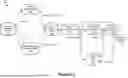


Sources:
- United States Patent and Trademark Office - verify current appl. status at the USPTO↗
Recent applications in this class:
- » 20260147122 2026-05-28
Methods of Using Background Images from a Light Detection and Ranging (LIDAR) Device - » 20260140265 2026-05-21
METHOD AND DEVICE FOR DETECTING OBSTACLE, MEDIUM AND ELECTRONIC DEVICE - » 20260126552 2026-05-07
SYSTEMS AND METHODS FOR CLOCK-SKEW SEARCH TO IMPROVE DEPTH ACCURACY IN GEIGER MODE LIDAR - » 20260110802 2026-04-23
METHOD FOR GENERATING TRAINING DATA FOR A MACHINE LEARNING MODEL - » 20260098965 2026-04-09
METHOD AND APPARATUS FOR DETERMINING OBJECT STATE INFORMATION, MEDIUM, DEVICE AND PROGRAM PRODUCT - » 20260093039 2026-04-02
INFORMATION PROCESSING APPARATUS, INFORMATION PROCESSING METHOD, AND AUTONOMOUS MOBILE BODY - » 20260086240 2026-03-26
LIDAR WITH GUARD LASER BEAM AND ADAPTIVE HIGH-INTENSITY LASER BEAM - » 20260086239 2026-03-26
LIGHTING MODULE FOR LIDAR APPARATUS - » 20260086238 2026-03-26
OBJECT DETECTION APPARATUS - » 20260079258 2026-03-19
MULTI-VIEW LIDAR PERCEPTION WITH MOTION CUES FOR AUTONOMOUS MACHINES AND APPLICATIONS