MAGNETIC REORIENTATION FOR SECURING PLAYBACK DEVICES
US20260147526A1
2026-05-28
19/392,444
2025-11-18
Smart Summary: A system helps keep devices in the right position while they charge wirelessly. It includes two devices: one that sends power and another that receives it. The first device has magnets that help align and hold the second device in place during charging. These magnets can change their polarity to match the magnets in the second device, ensuring a secure connection. This system works with different types of devices that may have different magnet orientations. 🚀 TL;DR
Abstract:
A system for magnetic reorientation is provided to secure and align devices during wireless charging. The system comprises a first device and a second device. The first device includes a power transfer coil configured to transfer power inductively between the first device and the second device; and one or more dock magnets configured to align and secure the second device to the first device during power transfer, wherein the one or more dock magnets are configured to provide reorientation of magnetic polarity based on a magnetic polarity orientation of one or more device magnets located in the second device. The first device is compatible with a plurality of device types including a first device type having a first magnet orientation and a second device type having a second magnet orientation, and the one or more dock magnets are configured to reorient based on the magnet orientation of the first device.
Inventors:
- Joern Riemer 3 🇺🇸 Boston, MA, United States
- Chadwick J. Souza 1 🇺🇸 Providence, RI, United States
Applicant:
Interested in similar patents?
Get notified when new applications in this technology area are published.
Classification:
G06F3/162 » CPC main
Input arrangements for transferring data to be processed into a form capable of being handled by the computer; Output arrangements for transferring data from processing unit to output unit, e.g. interface arrangements; Sound input; Sound output Interface to dedicated audio devices, e.g. audio drivers, interface to CODECs
G06F3/165 » CPC further
Input arrangements for transferring data to be processed into a form capable of being handled by the computer; Output arrangements for transferring data from processing unit to output unit, e.g. interface arrangements; Sound input; Sound output Management of the audio stream, e.g. setting of volume, audio stream path
H01F7/02 » CPC further
Magnets Permanent magnets [PM]
H02J50/10 » CPC further
Circuit arrangements or systems for wireless supply or distribution of electric power using inductive coupling
H04R5/02 » CPC further
Stereophonic arrangements Spatial or constructional arrangements of loudspeakers
H04S3/008 » CPC further
Systems employing more than two channels, e.g. quadraphonic in which the audio signals are in digital form, i.e. employing more than two discrete digital channels
H04R2420/07 » CPC further
Details of connection covered by , not provided for in its groups Applications of wireless loudspeakers or wireless microphones
H04S2400/01 » CPC further
Details of stereophonic systems covered by but not provided for in its groups Multi-channel, i.e. more than two input channels, sound reproduction with two speakers wherein the multi-channel information is substantially preserved
G06F3/16 IPC
Input arrangements for transferring data to be processed into a form capable of being handled by the computer; Output arrangements for transferring data from processing unit to output unit, e.g. interface arrangements Sound input; Sound output
H04S3/00 IPC
Systems employing more than two channels, e.g. quadraphonic
Description
CROSS-REFERENCE TO RELATED APPLICATIONS
This application claims priority under 35 U.S.C. § 119(e), to co-pending U.S. Provisional Application No. 63/725,259 filed Nov. 26, 2024, titled MAGNETIC REORIENTATION FOR SECURING PLAYBACK DEVICES, which is hereby incorporated herein by reference in its entirety.
FIELD OF THE DISCLOSURE
The present disclosure is related to consumer goods and, more particularly, to methods, systems, products, features, services, and other elements directed to media playback or some aspect thereof.
BACKGROUND
Options for accessing and listening to digital audio in an out-loud setting were limited until in 2002, when Sonos, Inc. began development of a new type of playback system. Sonos then filed one of its first patent applications in 2003, entitled “Method for Synchronizing Audio Playback between Multiple Networked Devices,” and began offering its first media playback systems for sale in 2005. The SONOS Wireless Home Sound System enables people to experience music from many sources via one or more networked playback devices. Through a software control application installed on a controller (e.g., smartphone, tablet, computer, voice input device), one can play what she wants in any room having a networked playback device. Media content (e.g., songs, podcasts, video sound) can be streamed to playback devices such that each room with a playback device can play back corresponding different media content. In addition, rooms can be grouped together for synchronous playback of the same media content, and/or the same media content can be heard in all rooms synchronously.
BRIEF DESCRIPTION OF THE DRAWINGS
Features, aspects, and advantages of the presently disclosed technology may be better understood with regard to the following description, appended claims, and accompanying drawings, as listed below. A person skilled in the relevant art will understand that the features shown in the drawings are for purposes of illustrations, and variations, including different and/or additional features and arrangements thereof, are possible.
FIG. 1A is a partial cutaway view of an environment having a media playback system configured in accordance with aspects of the disclosed technology.
FIG. 1B is a schematic diagram of the media playback system of FIG. 1A and one or more networks.
FIG. 1C is a block diagram of a playback device.
FIG. 1D is a block diagram of a playback device.
FIG. 1E is a block diagram of a bonded playback device.
FIG. 1F is a block diagram of a network microphone device.
FIG. 1G is a block diagram of a playback device.
FIG. 1H is a partial schematic diagram of a control device.
FIGS. 1I through 1L are schematic diagrams of corresponding media playback system zones.
FIG. 1M is a schematic diagram of media playback system areas.
FIG. 2A is a front isometric view of a playback device configured in accordance with aspects of the disclosed technology.
FIG. 2B is a front isometric view of the playback device of FIG. 2A without a grille.
FIG. 2C is an exploded view of the playback device of FIG. 2A.
FIG. 3A is a front view of a network microphone device configured in accordance with aspects of the disclosed technology.
FIG. 3B is a side isometric view of the network microphone device of FIG. 3A.
FIG. 3C is an exploded view of the network microphone device of FIGS. 3A and 3B.
FIG. 3D is an enlarged view of a portion of FIG. 3B.
FIG. 3E is a block diagram of the network microphone device of FIGS. 3A-3D.
FIG. 3F is a schematic diagram of an example voice input.
FIGS. 4A-4D are schematic diagrams of a control device in various stages of operation in accordance with aspects of the disclosed technology.
FIG. 5 is a front view of a control device.
FIG. 6 is a message flow diagram of a media playback system.
FIG. 7 illustrates a power consuming device coupled to a playback device.
FIG. 8 illustrates a power consuming device coupled to a wireless charging dock.
FIG. 9 illustrates an unsuccessful coupling of a playback device to a wireless charging dock with incompatible magnetic polarities.
FIG. 10 illustrates magnetic repulsion and attraction associated with varying orientations of device docking magnets.
FIG. 11 illustrates magnetic reorientation of device docking magnets.
FIG. 12 illustrates encapsulation of a device docking magnet.
FIG. 13 illustrates an electromagnet system implementation.
The drawings are for the purpose of illustrating example embodiments, but those of ordinary skill in the art will understand that the technology disclosed herein is not limited to the arrangements and/or instrumentality shown in the drawings.
DETAILED DESCRIPTION
I. Overview
SONOS, Inc. has a long history of innovating in the wireless audio space as demonstrated by the successful launch of numerous wireless audio products including, for example, SONOS ROAM, SONOS MOVE, SONOS ERA 100, SONOS ERA 300, SONOS FIVE, SONOS RAY, SONOS BEAM, SONOS ARC, SONOS PORT, and SONOS AMP. Building upon years of experience creating sophisticated, yet easy-to-use, audio products, SONOS, Inc. has appreciated the importance of providing a high quality user experience. This high quality user experience includes ease of use and flexible options for operation. For example, consumers desire a variety of types of playback devices that are suitable for different environments and listening situations, including home theater environments, outdoor social events, and portable applications.
One such portable application includes the use of a portable playback device that may be removably coupled to another power consuming device (e.g., another playback device, a user device, etc.) to provide an improved audio experience (e.g., compared to the quality of audio from a single playback device alone or that would otherwise be delivered by a user device such as a smartphone). One method of coupling the portable playback device to another power consuming device makes use of docking magnets that are included in many electronics devices (e.g., portable electronics devices such as portable speakers, smartphones, and smart watches) that have wireless charging capability (e.g., MAGSAFE compatible devices, QI2 compatible devices, etc.). Magnets employed in the portable playback device may be oriented to provide an attractive force to the magnets in the other power consuming device, thereby securing the playback device to the other power consuming device.
It is also desirable, however, to allow the playback device to have a wireless charging capability. Unfortunately, if the magnets of the playback device are oriented to provide an attractive force to another power consuming device, then those magnets will exert a repulsive force to a charging device (e.g., a wireless charging dock) that will prevent use of that charging device. Accordingly, techniques are provided herein for coupling of playback devices to other devices, including power consuming devices and charging devices (e.g., wireless charging docks), based on magnetic reorientation of docking magnets in one or more of the devices.
To this end, embodiments described herein relate to reorientation of docking magnets within one or more devices to secure those devices to each other during wireless charging and/or operation of the devices. In some embodiments, for example, the docking magnets within at least one device (e.g., the portable playback device) may be configured to spin freely about an axis. In this configuration, those magnets will orient themselves in response to the attractive force of the magnets in the mating device (e.g., smartphone or charging dock) such that a secure coupling is achieved between the devices.
In some examples, the docking magnets may be housed in a capsule containing a lubricating substance to allow the magnets to reorient themselves in response to an attractive magnetic force applied by the magnets of another mating device.
In some examples, the docking magnets may be electromagnets, and the polarity of those electromagnets may be adjusted by changing the direction of the current that drives the electromagnets. In such examples, a sensor may be employed to sense the magnetic polarity of the magnets of the other mating device, and the current direction may then be set based on that sensed polarity.
In some examples, a system for magnetic reorientation is provided to secure and align a first device to a second device during wireless charging and/or operation. The first device includes a power transfer coil configured to transfer power inductively between the first device and the second device. One or more dock magnets are configured to align and secure the second device to the first device during power transfer and/or operation, wherein the one or more dock magnets are configured to provide reorientation of magnetic polarity based on a magnetic polarity orientation of one or more device magnets located in the second device. The disclosed techniques allow the first device to be compatible with a plurality of device types including a first device type having a first magnet orientation and a second device type having a second magnet orientation, wherein the one or more dock magnets are configured to reorient based on the magnet orientation of the first device.
While some examples described herein may refer to functions performed by given actors such as “users,” “listeners,” and/or other entities, it should be understood that such references are for purposes of explanation only. The claims should not be interpreted to require action by any such example actor unless explicitly required by the language of the claims themselves.
In the Figures, identical reference numbers identify generally similar, and/or identical, elements. To facilitate the discussion of any particular element, the most significant digit or digits of a reference number refers to the Figure in which that element is first introduced. For example, element 110a is first introduced and discussed with reference to FIG. 1A. Many of the details, dimensions, angles, and other features shown in the Figures are merely illustrative of particular embodiments of the disclosed technology. Accordingly, other embodiments can have other details, dimensions, angles, and features without departing from the spirit or scope of the disclosure. In addition, those of ordinary skill in the art will appreciate that further embodiments of the various disclosed technologies can be practiced without several of the details described below.
II. Suitable Operating Environment
FIG. 1A is a partial cutaway view of a media playback system 100 distributed in an environment 101 (e.g., a house). The media playback system 100 comprises one or more playback devices 110 (identified individually as playback devices 110a-n), one or more network microphone devices 120 (“NMDs”) (identified individually as NMDs 120a-c), and one or more control devices 130 (identified individually as control devices 130a and 130b).
As used herein the term “playback device” can generally refer to a network device configured to receive, process, and output data of a media playback system. For example, a playback device can be a network device that receives and processes audio content. In some embodiments, a playback device includes one or more transducers or speakers powered by one or more amplifiers. In other embodiments, however, a playback device includes one of (or neither of) the speaker and the amplifier. For instance, a playback device can comprise one or more amplifiers configured to drive one or more speakers external to the playback device via a corresponding wire or cable.
Moreover, as used herein the term “NMD” (i.e., a “network microphone device”) can generally refer to a network device that is configured for audio detection. In some embodiments, an NMD is a stand-alone device configured primarily for audio detection. In other embodiments, an NMD is incorporated into a playback device (or vice versa).
The term “control device” can generally refer to a network device configured to perform functions relevant to facilitating user access, control, and/or configuration of the media playback system 100.
Each of the playback devices 110 is configured to receive audio signals or data from one or more media sources (e.g., one or more remote servers, one or more local devices, etc.) and play back the received audio signals or data as sound. The one or more NMDs 120 are configured to receive spoken word commands, and the one or more control devices 130 are configured to receive user input. In response to the received spoken word commands and/or user input, the media playback system 100 can play back audio via one or more of the playback devices 110. In certain embodiments, the playback devices 110 are configured to commence playback of media content in response to a trigger. For instance, one or more of the playback devices 110 can be configured to play back a morning playlist upon detection of an associated trigger condition (e.g., presence of a user in a kitchen, detection of a coffee machine operation, etc.). In some embodiments, for example, the media playback system 100 is configured to play back audio from a first playback device (e.g., the playback device 110a) in synchrony with a second playback device (e.g., the playback device 110b). Interactions between the playback devices 110, NMDs 120, and/or control devices 130 of the media playback system 100 configured in accordance with the various embodiments of the disclosure are described in greater detail below with respect to FIGS. 1B-6.
In the illustrated embodiment of FIG. 1A, the environment 101 comprises a household having several rooms, spaces, and/or playback zones, including (clockwise from upper left) a master bathroom 101a, a master bedroom 101b, a second bedroom 101c, a family room or den 101d, an office 101e, a living room 101f, a dining room 101g, a kitchen 101h, and an outdoor patio 101i. While certain embodiments and examples are described below in the context of a home environment, the technologies described herein may be implemented in other types of environments. In some embodiments, for example, the media playback system 100 can be implemented in one or more commercial settings (e.g., a restaurant, mall, airport, hotel, a retail or other store), one or more vehicles (e.g., a sports utility vehicle, bus, car, a ship, a boat, an airplane, etc.), multiple environments (e.g., a combination of home and vehicle environments), and/or another suitable environment where multi-zone audio may be desirable.
The media playback system 100 can comprise one or more playback zones, some of which may correspond to the rooms in the environment 101. The media playback system 100 can be established with one or more playback zones, after which additional zones may be added, or removed, to form, for example, the configuration shown in FIG. 1A. Each zone may be given a name according to a different room or space such as the office 101e, master bathroom 101a, master bedroom 101b, the second bedroom 101c, kitchen 101h, dining room 101g, living room 101f, and/or the balcony 101i. In some aspects, a single playback zone may include multiple rooms or spaces. In certain aspects, a single room or space may include multiple playback zones.
In the illustrated embodiment of FIG. 1A, the second bedroom 101c, the office 101e, the living room 101f, the dining room 101g, the kitchen 101h, and the outdoor patio 101i each include one playback device 110, and the master bathroom 101a, the master bedroom 101b, and the den 101d include a plurality of playback devices 110. In the master bedroom 101b, the playback devices 110l and 110m may be configured, for example, to play back audio content in synchrony as individual ones of playback devices 110, as a bonded playback zone, as a consolidated playback device, and/or any combination thereof. Similarly, in the den 101d, the playback devices 110h-k can be configured, for instance, to play back audio content in synchrony as individual ones of playback devices 110, as one or more bonded playback devices, and/or as one or more consolidated playback devices. Additional details regarding bonded and consolidated playback devices are described below with respect to FIGS. 1B, 1E, and 1I-1M.
In some aspects, one or more of the playback zones in the environment 101 may each be playing different audio content. For instance, a user may be grilling on the patio 101i and listening to hip hop music being played by the playback device 110c while another user is preparing food in the kitchen 101h and listening to classical music played by the playback device 110b. In another example, a playback zone may play the same audio content in synchrony with another playback zone. For instance, the user may be in the office 101e listening to the playback device 110f playing back the same hip hop music being played back by playback device 110c on the patio 101i. In some aspects, the playback devices 110c and 110f play back the hip hop music in synchrony such that the user perceives that the audio content is being played seamlessly (or at least substantially seamlessly) while moving between different playback zones. Additional details regarding audio playback synchronization among playback devices and/or zones can be found, for example, in U.S. Pat. No. 8,234,395 entitled, “System and method for synchronizing operations among a plurality of independently clocked digital data processing devices,” which is incorporated herein by reference in its entirety.
a. Suitable Media Playback System
FIG. 1B is a schematic diagram of the media playback system 100 and a cloud network 102. For ease of illustration, certain devices of the media playback system 100 and the cloud network 102 are omitted from FIG. 1B. One or more communication links 103 (referred to hereinafter as “the links 103”) communicatively couple the media playback system 100 and the cloud network 102.
The links 103 can comprise, for example, one or more wired networks, one or more wireless networks, one or more wide area networks (WAN), one or more local area networks (LAN), one or more personal area networks (PAN), one or more telecommunication networks (e.g., one or more Global System for Mobiles (GSM) networks, Code Division Multiple Access (CDMA) networks, Long-Term Evolution (LTE) networks, 5G communication networks, and/or other suitable data transmission protocol networks), etc. The cloud network 102 is configured to deliver media content (e.g., audio content, video content, photographs, social media content, etc.) to the media playback system 100 in response to a request transmitted from the media playback system 100 via the links 103. In some embodiments, the cloud network 102 is further configured to receive data (e.g., voice input data) from the media playback system 100 and correspondingly transmit commands and/or media content to the media playback system 100.
The cloud network 102 comprises computing devices 106 (identified separately as a first computing device 106a, a second computing device 106b, and a third computing device 106c). The computing devices 106 can comprise individual computers or servers, such as, for example, a media streaming service server storing audio and/or other media content, a voice service server, a social media server, a media playback system control server, etc. In some embodiments, one or more of the computing devices 106 comprise modules of a single computer or server. In certain embodiments, one or more of the computing devices 106 comprise one or more modules, computers, and/or servers. Moreover, while the cloud network 102 is described above in the context of a single cloud network, in some embodiments the cloud network 102 comprises a plurality of cloud networks comprising communicatively coupled computing devices. Furthermore, while the cloud network 102 is shown in FIG. 1B as having three of the computing devices 106, in some embodiments, the cloud network 102 comprises fewer (or more than) three computing devices 106.
The media playback system 100 is configured to receive media content from the networks 102 via the links 103. The received media content can comprise, for example, a Uniform Resource Identifier (URI) and/or a Uniform Resource Locator (URL). For instance, in some examples, the media playback system 100 can stream, download, or otherwise obtain data from a URI or a URL corresponding to the received media content. A network 104 communicatively couples the links 103 and at least a portion of the devices (e.g., one or more of the playback devices 110, NMDs 120, and/or control devices 130) of the media playback system 100. The network 104 can include, for example, a wireless network (e.g., a WI-FI network, a BLUETOOTH network, a Z-WAVE network, a ZIGBEE network, and/or other suitable wireless communication protocol network) and/or a wired network (e.g., a network comprising Ethernet, Universal Serial Bus (USB), and/or another suitable wired communication). As those of ordinary skill in the art will appreciate, as used herein, “WI-FI” can refer to several different communication protocols including, for example, Institute of Electrical and Electronics Engineers (IEEE) 802.11a, 802.11b, 802.11g, 802.11n, 802.11ac, 802.11ac, 802.11ad, 802.11af, 802.11ah, 802.11ai, 802.11aj, 802.11aq, 802.11ax, 802.11ay, 802.15, etc. transmitted at 2.4 Gigahertz (GHz), 5 GHz, and/or another suitable frequency.
In some embodiments, the network 104 comprises a dedicated communication network that the media playback system 100 uses to transmit messages between individual devices and/or to transmit media content to and from media content sources (e.g., one or more of the computing devices 106). In certain embodiments, the network 104 is configured to be accessible only to devices in the media playback system 100, thereby reducing interference and competition with other household devices. In other embodiments, however, the network 104 comprises an existing household or commercial facility communication network (e.g., a household or commercial facility WI-FI network). In some embodiments, the links 103 and the network 104 comprise one or more of the same networks. In some aspects, for example, the links 103 and the network 104 comprise a telecommunication network (e.g., an LTE network, a 5G network, etc.). Moreover, in some embodiments, the media playback system 100 is implemented without the network 104, and devices comprising the media playback system 100 can communicate with each other, for example, via one or more direct connections, PANs, telecommunication networks, and/or other suitable communication links. The network 104 may be referred to herein as a “local communication network” to differentiate the network 104 from the cloud network 102 that couples the media playback system 100 to remote devices, such as cloud servers that host cloud services.
In some embodiments, audio content sources may be regularly added or removed from the media playback system 100. In some embodiments, for example, the media playback system 100 performs an indexing of media items when one or more media content sources are updated, added to, and/or removed from the media playback system 100. The media playback system 100 can scan identifiable media items in some or all folders and/or directories accessible to the playback devices 110, and generate or update a media content database comprising metadata (e.g., title, artist, album, track length, etc.) and other associated information (e.g., URIs, URLs, etc.) for each identifiable media item found. In some embodiments, for example, the media content database is stored on one or more of the playback devices 110, network microphone devices 120, and/or control devices 130.
In the illustrated embodiment of FIG. 1B, the playback devices 110l and 110m comprise a group 107a. The playback devices 110l and 110m can be positioned in different rooms and be grouped together in the group 107a on a temporary or permanent basis based on user input received at the control device 130a and/or another control device 130 in the media playback system 100. When arranged in the group 107a, the playback devices 110l and 110m can be configured to play back the same or similar audio content in synchrony from one or more audio content sources. In certain embodiments, for example, the group 107a comprises a bonded zone in which the playback devices 110l and 110m comprise left audio and right audio channels, respectively, of multi-channel audio content, thereby producing or enhancing a stereo effect of the audio content. In some embodiments, the group 107a includes additional playback devices 110. In other embodiments, however, the media playback system 100 omits the group 107a and/or other grouped arrangements of the playback devices 110. Additional details regarding groups and other arrangements of playback devices are described in further detail below with respect to FIGS. 1I-1M.
The media playback system 100 includes the NMDs 120a and 120b, each comprising one or more microphones configured to receive voice utterances from a user. In the illustrated embodiment of FIG. 1B, the NMD 120a is a standalone device and the NMD 120b is integrated into the playback device 110n. The NMD 120a, for example, is configured to receive voice input 121 from a user 123. In some embodiments, the NMD 120a transmits data associated with the received voice input 121 to a voice assistant service (VAS) configured to (i) process the received voice input data and (ii) facilitate one or more operations on behalf of the media playback system 100.
In some aspects, for example, the computing device 106c comprises one or more modules and/or servers of a VAS (e.g., a VAS operated by one or more of SONOS, AMAZON, GOOGLE, APPLE, MICROSOFT, etc.). The computing device 106c can receive the voice input data from the NMD 120a via the network 104 and the links 103.
In response to receiving the voice input data, the computing device 106c processes the voice input data (i.e., “Play Hey Jude by The Beatles”), and determines that the processed voice input includes a command to play a song (e.g., “Hey Jude”). In some embodiments, after processing the voice input, the computing device 106c accordingly transmits commands to the media playback system 100 to play back “Hey Jude” by the Beatles from a suitable media service (e.g., via one or more of the computing devices 106) on one or more of the playback devices 110. In other embodiments, the computing device 106c may be configured to interface with media services on behalf of the media playback system 100. In such embodiments, after processing the voice input, instead of the computing device 106c transmitting commands to the media playback system 100 causing the media playback system 100 to retrieve the requested media from a suitable media service, the computing device 106c itself causes a suitable media service to provide the requested media to the media playback system 100 in accordance with the user's voice utterance.
b. Suitable Playback Devices
FIG. 1C is a block diagram of the playback device 110a comprising an input/output 111. The input/output 111 can include an analog I/O 111a (e.g., one or more wires, cables, and/or other suitable communication links configured to carry analog signals) and/or a digital I/O 111b (e.g., one or more wires, cables, or other suitable communication links configured to carry digital signals). In some embodiments, the analog I/O 111a is an audio line-in input connection comprising, for example, an auto-detecting 3.5 mm audio line-in connection. In some embodiments, the digital I/O 111b comprises a Sony/Philips Digital Interface Format (S/PDIF) communication interface and/or cable and/or a Toshiba Link (TOSLINK) cable. In some embodiments, the digital I/O 111b comprises a High-Definition Multimedia Interface (HDMI) interface and/or cable. In some embodiments, the digital I/O 111b includes one or more wireless communication links comprising, for example, a radio frequency (RF), infrared, WI-FI, BLUETOOTH, or another suitable communication link. In certain embodiments, the analog I/O 111a and the digital I/O 111b comprise interfaces (e.g., ports, plugs, jacks, etc.) configured to receive connectors of cables transmitting analog and digital signals, respectively, without necessarily including cables.
The playback device 110a, for example, can receive media content (e.g., audio content comprising music and/or other sounds) from a local audio source 105 via the input/output 111 (e.g., a cable, a wire, a PAN, a BLUETOOTH connection, an ad hoc wired or wireless communication network, and/or another suitable communication link). The local audio source 105 can comprise, for example, a mobile device (e.g., a smartphone, a tablet, a laptop computer, etc.) or another suitable audio component (e.g., a television, a desktop computer, an amplifier, a phonograph (such as an LP turntable), a Blu-ray player, a memory storing digital media files, etc.). In some aspects, the local audio source 105 includes local music libraries on a smartphone, a computer, a networked-attached storage (NAS), and/or another suitable device configured to store media files. In certain embodiments, one or more of the playback devices 110, NMDs 120, and/or control devices 130 comprise the local audio source 105. In other embodiments, however, the media playback system omits the local audio source 105 altogether. In some embodiments, the playback device 110a does not include an input/output 111 and receives all audio content via the network 104.
The playback device 110a further comprises electronics 112, a user interface 113 (e.g., one or more buttons, knobs, dials, touch-sensitive surfaces, displays, touchscreens, etc.), and one or more transducers 114 (referred to hereinafter as “the transducers 114”). The electronics 112 are configured to receive audio from an audio source (e.g., the local audio source 105) via the input/output 111 or one or more of the computing devices 106a-c via the network 104 (FIG. 1B), amplify the received audio, and output the amplified audio for playback via one or more of the transducers 114. In some embodiments, the playback device 110a optionally includes one or more microphones 115 (e.g., a single microphone, a plurality of microphones, a microphone array) (hereinafter referred to as “the microphones 115”). In certain embodiments, for example, the playback device 110a having one or more of the optional microphones 115 can operate as an NMD configured to receive voice input from a user and correspondingly perform one or more operations based on the received voice input.
In the illustrated embodiment of FIG. 1C, the electronics 112 comprise one or more processors 112a (referred to hereinafter as “the processors 112a”), memory 112b, software components 112c, a network interface 112d, one or more audio processing components 112g (referred to hereinafter as “the audio components 112g”), one or more audio amplifiers 112h (referred to hereinafter as “the amplifiers 112h”), and power 112i (e.g., one or more power supplies, power cables, power receptacles, batteries, induction coils, Power-over Ethernet (POE) interfaces, and/or other suitable sources of electric power). In some embodiments, the electronics 112 optionally include one or more other components 112j (e.g., one or more sensors, video displays, touchscreens, battery charging bases, etc.).
The processors 112a can comprise clock-driven computing component(s) configured to process data, and the memory 112b can comprise a computer-readable medium (e.g., a tangible, non-transitory computer-readable medium loaded with one or more of the software components 112c) configured to store instructions for performing various operations and/or functions. The processors 112a are configured to execute the instructions stored on the memory 112b to perform one or more of the operations. The operations can include, for example, causing the playback device 110a to retrieve audio data from an audio source (e.g., one or more of the computing devices 106a-c (FIG. 1B)), and/or another one of the playback devices 110. In some embodiments, the operations further include causing the playback device 110a to send audio data to another one of the playback devices 110a and/or another device (e.g., one of the NMDs 120). Certain embodiments include operations causing the playback device 110a to pair with another of the one or more playback devices 110 to enable a multi-channel audio environment (e.g., a stereo pair, a bonded zone, etc.).
The processors 112a can be further configured to perform operations causing the playback device 110a to synchronize playback of audio content with another of the one or more playback devices 110. As those of ordinary skill in the art will appreciate, during synchronous playback of audio content on a plurality of playback devices, a listener will preferably be unable to perceive time-delay differences between playback of the audio content by the playback device 110a and the other one or more other playback devices 110. Additional details regarding audio playback synchronization among playback devices can be found, for example, in U.S. Pat. No. 8,234,395, which was incorporated by reference above.
In some embodiments, the memory 112b is further configured to store data associated with the playback device 110a, such as one or more zones and/or zone groups of which the playback device 110a is a member, audio sources accessible to the playback device 110a, and/or a playback queue that the playback device 110a (and/or another of the one or more playback devices) can be associated with. The stored data can comprise one or more state variables that are periodically updated and used to describe a state of the playback device 110a. The memory 112b can also include data associated with a state of one or more of the other devices (e.g., the playback devices 110, NMDs 120, control devices 130) of the media playback system 100. In some aspects, for example, the state data is shared during predetermined intervals of time (e.g., every 5 seconds, every 10 seconds, every 60 seconds, etc.) among at least a portion of the devices of the media playback system 100, so that one or more of the devices have the most recent data associated with the media playback system 100.
The network interface 112d is configured to facilitate a transmission of data between the playback device 110a and one or more other devices on a data network such as, for example, the links 103 and/or the network 104 (FIG. 1B). The network interface 112d is configured to transmit and receive data corresponding to media content (e.g., audio content, video content, text, photographs) and other signals (e.g., non-transitory signals) comprising digital packet data including an Internet Protocol (IP)-based source address and/or an IP-based destination address. The network interface 112d can parse the digital packet data such that the electronics 112 properly receive and process the data destined for the playback device 110a.
In the illustrated embodiment of FIG. 1C, the network interface 112d comprises one or more wireless interfaces 112e (referred to hereinafter as “the wireless interface 112e”). The wireless interface 112e (e.g., a suitable interface comprising one or more antennae) can be configured to wirelessly communicate with one or more other devices (e.g., one or more of the other playback devices 110, NMDs 120, and/or control devices 130) that are communicatively coupled to the network 104 (FIG. 1B) in accordance with a suitable wireless communication protocol (e.g., WI-FI, BLUETOOTH, LTE, etc.). In some embodiments, the network interface 112d optionally includes a wired interface 112f (e.g., an interface or receptacle configured to receive a network cable such as an Ethernet, a USB-A, USB-C, and/or Thunderbolt cable) configured to communicate over a wired connection with other devices in accordance with a suitable wired communication protocol. In certain embodiments, the network interface 112d includes the wired interface 112f and excludes the wireless interface 112e. In some embodiments, the electronics 112 exclude the network interface 112d altogether and transmit and receive media content and/or other data via another communication path (e.g., the input/output 111).
The audio components 112g are configured to process and/or filter data comprising media content received by the electronics 112 (e.g., via the input/output 111 and/or the network interface 112d) to produce output audio signals. In some embodiments, the audio processing components 112g comprise, for example, one or more digital-to-analog converters (DACs), audio preprocessing components, audio enhancement components, digital signal processors (DSPs), and/or other suitable audio processing components, modules, circuits, etc. In certain embodiments, one or more of the audio processing components 112g can comprise one or more subcomponents of the processors 112a. In some embodiments, the electronics 112 omit the audio processing components 112g. In some aspects, for example, the processors 112a execute instructions stored on the memory 112b to perform audio processing operations to produce the output audio signals.
The amplifiers 112h are configured to receive and amplify the audio output signals produced by the audio processing components 112g and/or the processors 112a. The amplifiers 112h can comprise electronic devices and/or components configured to amplify audio signals to levels sufficient for driving one or more of the transducers 114. In some embodiments, for example, the amplifiers 112h include one or more switching or class-D power amplifiers. In other embodiments, however, the amplifiers 112h include one or more other types of power amplifiers (e.g., linear gain power amplifiers, class-A amplifiers, class-B amplifiers, class-AB amplifiers, class-C amplifiers, class-D amplifiers, class-E amplifiers, class-F amplifiers, class-G amplifiers, class H amplifiers, and/or another suitable type of power amplifier). In certain embodiments, the amplifiers 112h comprise a suitable combination of two or more of the foregoing types of power amplifiers. Moreover, in some embodiments, individual ones of the amplifiers 112h correspond to individual ones of the transducers 114. In other embodiments, however, the electronics 112 include a single one of the amplifiers 112h configured to output amplified audio signals to a plurality of the transducers 114. In some other embodiments, the electronics 112 omit the amplifiers 112h.
The transducers 114 (e.g., one or more speakers and/or speaker drivers) receive the amplified audio signals from the amplifier 112h and render or output the amplified audio signals as sound (e.g., audible sound waves having a frequency between about 20 Hertz (Hz) and 20 kilohertz (kHz)). In some embodiments, the transducers 114 can comprise a single transducer. In other embodiments, however, the transducers 114 comprise a plurality of audio transducers. In some embodiments, the transducers 114 comprise more than one type of transducer. For example, the transducers 114 can include one or more low frequency transducers (e.g., subwoofers, woofers), mid-range frequency transducers (e.g., mid-range transducers, mid-woofers), and one or more high frequency transducers (e.g., one or more tweeters). As used herein, “low frequency” can generally refer to audible frequencies below about 500 Hz, “mid-range frequency” can generally refer to audible frequencies between about 500 Hz and about 2 kHz, and “high frequency” can generally refer to audible frequencies above 2 kHz. In certain embodiments, however, one or more of the transducers 114 comprise transducers that do not adhere to the foregoing frequency ranges. For example, one of the transducers 114 may comprise a mid-woofer transducer configured to output sound at frequencies between about 200 Hz and about 5 kHz.
By way of illustration, Sonos, Inc. presently offers (or has offered) for sale certain playback devices including, for example, a “SONOS ONE,” “PLAY:1,” “PLAY:3,” “PLAY:5,” “PLAYBAR,” “PLAYBASE,” “CONNECT:AMP,” “CONNECT,” “AMP,” “PORT,” and “SUB.” Other suitable playback devices may additionally or alternatively be used to implement the playback devices of example embodiments disclosed herein. Additionally, one of ordinary skill in the art will appreciate that a playback device is not limited to the examples described herein or to Sonos product offerings. In some embodiments, for example, one or more playback devices 110 comprise wired or wireless headphones (e.g., over-the-ear headphones, on-ear headphones, in-ear earphones, etc.). In other embodiments, one or more of the playback devices 110 comprise a docking station and/or an interface configured to interact with a docking station for personal mobile media playback devices. In certain embodiments, a playback device may be integral to another device or component such as a television, an LP turntable, a lighting fixture, or some other device for indoor or outdoor use. In some embodiments, a playback device omits a user interface and/or one or more transducers. For example, FIG. 1D is a block diagram of a playback device 110p comprising the input/output 111 and electronics 112 without the user interface 113 or transducers 114.
FIG. 1E is a block diagram of a bonded playback device 110q comprising the playback device 110a (FIG. 1C) sonically bonded with the playback device 110i (e.g., a subwoofer) (FIG. 1A). In the illustrated embodiment, the playback devices 110a and 110i are separate ones of the playback devices 110 housed in separate enclosures. In some embodiments, however, the bonded playback device 110q comprises a single enclosure housing both the playback devices 110a and 110i. The bonded playback device 110q can be configured to process and reproduce sound differently than an unbonded playback device (e.g., the playback device 110a of FIG. 1C) and/or paired or bonded playback devices (e.g., the playback devices 110l and 110m of FIG. 1B). In some embodiments, for example, the playback device 110a is a full-range playback device configured to render low frequency, mid-range frequency, and high frequency audio content, and the playback device 110i is a subwoofer configured to render low frequency audio content. In some aspects, the playback device 110a, when bonded with the first playback device, is configured to render only the mid-range and high frequency components of a particular audio content, while the playback device 110i renders the low frequency component of the particular audio content. In some embodiments, the bonded playback device 110q includes additional playback devices and/or another bonded playback device. Additional playback device embodiments are described in further detail below with respect to FIGS. 2A-3D.”
c. Suitable Network Microphone Devices (NMDs)
FIG. 1F is a block diagram of the NMD 120a (FIGS. 1A and 1B). The NMD 120a includes one or more voice processing components 124 (hereinafter “the voice components 124”) and several components described with respect to the playback device 110a (FIG. 1C) including the processors 112a, the memory 112b, and the microphones 115. The NMD 120a optionally comprises other components also included in the playback device 110a (FIG. 1C), such as the user interface 113 and/or the transducers 114. In some embodiments, the NMD 120a is configured as a media playback device (e.g., one or more of the playback devices 110), and further includes, for example, one or more of the audio components 112g (FIG. 1C), the amplifiers 112h, and/or other playback device components. In certain embodiments, the NMD 120a comprises an Internet of Things (IoT) device such as, for example, a thermostat, alarm panel, fire and/or smoke detector, etc. In some embodiments, the NMD 120a comprises the microphones 115, the voice processing components 124, and only a portion of the components of the electronics 112 described above with respect to FIG. 1C. In some aspects, for example, the NMD 120a includes the processor 112a and the memory 112b (FIG. 1C), while omitting one or more other components of the electronics 112. In some embodiments, the NMD 120a includes additional components (e.g., one or more sensors, cameras, thermometers, barometers, hygrometers, etc.).
In some embodiments, an NMD can be integrated into a playback device. FIG. 1G is a block diagram of a playback device 110r comprising an NMD 120d. The playback device 110r can comprise many or all of the components of the playback device 110a and further include the microphones 115 and voice processing components 124 (FIG. 1F). The playback device 110r optionally includes an integrated control device 130c. The control device 130c can comprise, for example, a user interface (e.g., the user interface 113 of FIG. 1C) configured to receive user input (e.g., touch input, voice input, etc.) without a separate control device. In other embodiments, however, the playback device 110r receives commands from another control device (e.g., the control device 130a of FIG. 1B). Additional NMD embodiments are described in further detail below with respect to FIGS. 3A-3F.
Referring again to FIG. 1F, the microphones 115 are configured to acquire, capture, and/or receive sound from an environment (e.g., the environment 101 of FIG. 1A) and/or a room in which the NMD 120a is positioned. The received sound can include, for example, vocal utterances, audio played back by the NMD 120a and/or another playback device, background voices, ambient sounds, etc. The microphones 115 convert the received sound into electrical signals to produce microphone data. The voice processing components 124 receive and analyze the microphone data to determine whether a voice input is present in the microphone data. The voice input can comprise, for example, an activation word followed by an utterance including a user request. As those of ordinary skill in the art will appreciate, an activation word is a word or other audio cue signifying a user voice input. For instance, in querying the AMAZON VAS, a user might speak the activation word “Alexa.” Other examples include “Ok, Google” for invoking the GOOGLE VAS and “Hey, Siri” for invoking the APPLE VAS.
After detecting the activation word, voice processing components 124 monitor the microphone data for an accompanying user request in the voice input. The user request may include, for example, a command to control a third-party device, such as a thermostat (e.g., NEST thermostat), an illumination device (e.g., a PHILIPS HUE lighting device), or a media playback device (e.g., a SONOS playback device). For example, a user might speak the activation word “Alexa” followed by the utterance “set the thermostat to 68 degrees” to set a temperature in a home (e.g., the environment 101 of FIG. 1A). The user might speak the same activation word followed by the utterance “turn on the living room” to turn on illumination devices in a living room area of the home. The user may similarly speak an activation word followed by a request to play a particular song, an album, or a playlist of music on a playback device in the home. Additional description regarding receiving and processing voice input data can be found in further detail below with respect to FIGS. 3A-3F.
d. Suitable Control Devices
FIG. 1H is a partial schematic diagram of the control device 130a (FIGS. 1A and 1B). As used herein, the term “control device” can be used interchangeably with “controller” or “control system.” Among other features, the control device 130a is configured to receive user input related to the media playback system 100 and, in response, cause one or more devices in the media playback system 100 to perform an action(s) or operation(s) corresponding to the user input. In the illustrated embodiment, the control device 130a comprises a smartphone (e.g., an iPhone™, an Android phone, etc.) on which media playback system controller application software is installed. In some embodiments, the control device 130a comprises, for example, a tablet (e.g., an iPad™), a computer (e.g., a laptop computer, a desktop computer, etc.), and/or another suitable device (e.g., a television, an automobile audio head unit, an IoT device, etc.). In certain embodiments, the control device 130a comprises a dedicated controller for the media playback system 100. In other embodiments, as described above with respect to FIG. 1G, the control device 130a is integrated into another device in the media playback system 100 (e.g., one more of the playback devices 110, NMDs 120, and/or other suitable devices configured to communicate over a network).
The control device 130a includes electronics 132, a user interface 133, one or more speakers 134, and one or more microphones 135. The electronics 132 comprise one or more processors 132a (referred to hereinafter as “the processors 132a”), a memory 132b, software components 132c, and a network interface 132d. The processor 132a can be configured to perform functions relevant to facilitating user access, control, and configuration of the media playback system 100. The memory 132b can comprise data storage that can be loaded with one or more of the software components executable by the processor 132a to perform those functions. The software components 132c can comprise applications and/or other executable software configured to facilitate control of the media playback system 100. The memory 132b can be configured to store, for example, the software components 132c, media playback system controller application software, and/or other data associated with the media playback system 100 and the user.
The network interface 132d is configured to facilitate network communications between the control device 130a and one or more other devices in the media playback system 100, and/or one or more remote devices. In some embodiments, the network interface 132d is configured to operate according to one or more suitable communication industry standards (e.g., infrared, radio, wired standards including IEEE 802.3, wireless standards including IEEE 802.11a, 802.11b, 802.11g, 802.11n, 802.11ac, 802.15, 4G, LTE, etc.). The network interface 132d can be configured, for example, to transmit data to and/or receive data from the playback devices 110, the NMDs 120, other ones of the control devices 130, one of the computing devices 106 of FIG. 1B, devices comprising one or more other media playback systems, etc. The transmitted and/or received data can include, for example, playback device control commands, state variables, playback zone and/or zone group configurations. For instance, based on user input received at the user interface 133, the network interface 132d can transmit a playback device control command (e.g., volume control, audio playback control, audio content selection, etc.) from the control device 130a to one or more of the playback devices 110. The network interface 132d can also transmit and/or receive configuration changes such as, for example, adding/removing one or more playback devices 110 to/from a zone, adding/removing one or more zones to/from a zone group, forming a bonded or consolidated player, separating one or more playback devices from a bonded or consolidated player, among others. Additional description of zones and groups can be found below with respect to FIGS. 1I through 1M.
The user interface 133 is configured to receive user input and can facilitate control of the media playback system 100. The user interface 133 includes media content art 133a (e.g., album art, lyrics, videos, etc.), a playback status indicator 133b (e.g., an elapsed and/or remaining time indicator), media content information region 133c, a playback control region 133d, and a zone indicator 133e. The media content information region 133c can include a display of relevant information (e.g., title, artist, album, genre, release year, etc.) about media content currently playing and/or media content in a queue or playlist. The playback control region 133d can include selectable (e.g., via touch input and/or via a cursor or another suitable selector) icons to cause one or more playback devices in a selected playback zone or zone group to perform playback actions such as, for example, play or pause, fast forward, rewind, skip to next, skip to previous, enter/exit shuffle mode, enter/exit repeat mode, enter/exit cross fade mode, etc. The playback control region 133d may also include selectable icons to modify equalization settings, playback volume, and/or other suitable playback actions. In the illustrated embodiment, the user interface 133 comprises a display presented on a touch screen interface of a smartphone (e.g., an iPhone™, an Android phone, etc.). In some embodiments, however, user interfaces of varying formats, styles, and interactive sequences may alternatively be implemented on one or more network devices to provide comparable control access to a media playback system.
The one or more speakers 134 (e.g., one or more transducers) can be configured to output sound to the user of the control device 130a. In some embodiments, the one or more speakers comprise individual transducers configured to correspondingly output low frequencies, mid-range frequencies, and/or high frequencies. In some aspects, for example, the control device 130a is configured as a playback device (e.g., one of the playback devices 110). Similarly, in some embodiments the control device 130a is configured as an NMD (e.g., one of the NMDs 120), receiving voice commands and other sounds via the one or more microphones 135.
The one or more microphones 135 can comprise, for example, one or more condenser microphones, electret condenser microphones, dynamic microphones, and/or other suitable types of microphones or transducers. In some embodiments, two or more of the microphones 135 are arranged to capture location information of an audio source (e.g., voice, audible sound, etc.) and/or configured to facilitate filtering of background noise. Moreover, in certain embodiments, the control device 130a is configured to operate as a playback device and an NMD. In other embodiments, however, the control device 130a omits the one or more speakers 134 and/or the one or more microphones 135. For instance, the control device 130a may comprise a device (e.g., a thermostat, an IoT device, a network device, etc.) comprising a portion of the electronics 132 and the user interface 133 (e.g., a touch screen) without any speakers or microphones. Additional control device embodiments are described in further detail below with respect to FIGS. 4A-4D and 5.
e. Suitable Playback Device Configurations
FIGS. 1I through 1M show example configurations of playback devices in zones and zone groups. Referring first to FIG. 1M, in one example, a single playback device may belong to a zone. For example, the playback device 110g in the second bedroom 101c (FIG. 1A) may belong to Zone C. In some implementations described below, multiple playback devices may be “bonded” to form a “bonded pair” which together form a single zone. For example, the playback device 110l (e.g., a left playback device) can be bonded to the playback device 110m (e.g., a right playback device) to form Zone B. Bonded playback devices may have different playback responsibilities (e.g., channel responsibilities). In another implementation described below, multiple playback devices may be merged to form a single zone. For example, the playback device 110h (e.g., a front playback device) may be merged with the playback device 110i (e.g., a subwoofer), and the playback devices 110j and 110k (e.g., left and right surround speakers, respectively) to form a single Zone D. In another example, the playback devices 110b and 110d can be merged to form a merged group or a zone group 108b. The merged playback devices 110b and 110d may not be specifically assigned different playback responsibilities. That is, the merged playback devices 110b and 110d may, aside from playing audio content in synchrony, each play audio content as they would if they were not merged.
Each zone in the media playback system 100 may be provided for control as a single user interface (UI) entity. For example, Zone A may be provided as a single entity named Master Bathroom. Zone B may be provided as a single entity named Master Bedroom. Zone C may be provided as a single entity named Second Bedroom.
Playback devices that are bonded may have different playback responsibilities, such as responsibilities for certain audio channels. For example, as shown in FIG. 1I, the playback devices 110l and 110m may be bonded so as to produce or enhance a stereo effect of audio content. In this example, the playback device 110l may be configured to play a left channel audio component, while the playback device 110m may be configured to play a right channel audio component. In some implementations, such stereo bonding may be referred to as “pairing.”
Additionally, bonded playback devices may have additional and/or different respective speaker drivers. As shown in FIG. 1J, the playback device 110h named Front may be bonded with the playback device 110i named SUB. The Front device 110h can be configured to render a range of mid to high frequencies and the SUB device 110i can be configured to render low frequencies. When unbonded, however, the Front device 110h can be configured to render a full range of frequencies. As another example, FIG. 1K shows the Front and SUB devices 110h and 110i further bonded with Left and Right playback devices 110j and 110k, respectively. In some implementations, the Left and Right devices 110j and 110k can be configured to form surround or “satellite” channels of a home theater system. The bonded playback devices 110h, 110i, 110j, and 110k may form a single Zone D (FIG. 1M).
Playback devices that are merged may not have assigned playback responsibilities, and may each render the full range of audio content the respective playback device is capable of. Nevertheless, merged devices may be represented as a single UI entity (i.e., a zone, as discussed above). For instance, the playback devices 110a and 110n in the master bathroom have the single UI entity of Zone A. In one embodiment, the playback devices 110a and 110n may each output the full range of audio content each respective playback devices 110a and 110n are capable of, in synchrony.
In some embodiments, an NMD is bonded or merged with another device so as to form a zone. For example, the NMD 120b may be bonded with the playback device 110e, which together form Zone F, named Living Room. In other embodiments, a stand-alone network microphone device may be in a zone by itself. In other embodiments, however, a stand-alone network microphone device may not be associated with a zone. Additional details regarding associating network microphone devices and playback devices as designated or default devices may be found, for example, in subsequently referenced U.S. Pat. No. 10,499,146.
Zones of individual, bonded, and/or merged devices may be grouped to form a zone group. For example, referring to FIG. 1M, Zone A may be grouped with Zone B to form a zone group 108a that includes the two zones. Similarly, Zone G may be grouped with Zone H to form the zone group 108b. As another example, Zone A may be grouped with one or more other Zones C-I. The Zones A-I may be grouped and ungrouped in numerous ways. For example, three, four, five, or more (e.g., all) of the Zones A-I may be grouped. When grouped, the zones of individual and/or bonded playback devices may play back audio in synchrony with one another, as described in previously referenced U.S. Pat. No. 8,234,395. Playback devices may be dynamically grouped and ungrouped to form new or different groups that synchronously play back audio content.
In various implementations, the zones in an environment may be the default name of a zone within the group or a combination of the names of the zones within a zone group. For example, Zone Group 108b can be assigned a name such as “Dining+Kitchen”, as shown in FIG. 1M. In some embodiments, a zone group may be given a unique name selected by a user.
Certain data may be stored in a memory of a playback device (e.g., the memory 112b of FIG. 1C) as one or more state variables that are periodically updated and used to describe the state of a playback zone, the playback device(s), and/or a zone group associated therewith. The memory may also include the data associated with the state of the other devices of the media system, and shared from time to time among the devices so that one or more of the devices have the most recent data associated with the system.
In some embodiments, the memory may store instances of various variable types associated with the states. Variable instances may be stored with identifiers (e.g., tags) corresponding to type. For example, certain identifiers may be a first type “a1” to identify playback device(s) of a zone, a second type “b1” to identify playback device(s) that may be bonded in the zone, and a third type “c1” to identify a zone group to which the zone may belong. As a related example, identifiers associated with the second bedroom 101c may indicate that the playback device is the only playback device of the Zone C and not in a zone group. Identifiers associated with the Den may indicate that the Den is not grouped with other zones but includes bonded playback devices 110h-110k. Identifiers associated with the Dining Room may indicate that the Dining Room is part of the Dining+Kitchen zone group 108b and that devices 110b and 110d are grouped (FIG. 1L). Identifiers associated with the Kitchen may indicate the same or similar information by virtue of the Kitchen being part of the Dining+Kitchen zone group 108b. Other example zone variables and identifiers are described below.
In yet another example, the memory may store variables or identifiers representing other associations of zones and zone groups, such as identifiers associated with Areas, as shown in FIG. 1M. An area may involve a cluster of zone groups and/or zones not within a zone group. For instance, FIG. 1M shows an Upper Area 109a including Zones A-D and I, and a Lower Area 109b including Zones E-I. In one aspect, an Area may be used to invoke a cluster of zone groups and/or zones that share one or more zones and/or zone groups of another cluster. In another aspect, this differs from a zone group, which does not share a zone with another zone group. Further examples of techniques for implementing Areas may be found, for example, in U.S. Pat. No. 10,712,997 filed Aug. 21, 2017, and titled “Room Association Based on Name,” and U.S. Pat. No. 8,483,853 filed Sep. 11, 2007, and titled “Controlling and manipulating groupings in a multi-zone media system.” Each of these patents is incorporated herein by reference in its entirety. In some embodiments, the media playback system 100 may not implement Areas, in which case the system may not store variables associated with Areas.
III. Example Systems and Devices
FIG. 2A is a front isometric view of a playback device 210 configured in accordance with aspects of the disclosed technology. FIG. 2B is a front isometric view of the playback device 210 without a grille 216e. FIG. 2C is an exploded view of the playback device 210. Referring to FIGS. 2A-2C together, the playback device 210 comprises a housing 216 that includes an upper portion 216a, a right or first side portion 216b, a lower portion, a left or second side portion 216d, the grille 216e, and a rear portion 216f. A plurality of fasteners 216g (e.g., one or more screws, rivets, clips) attaches a frame 216h to the housing 216. A cavity 216j (FIG. 2C) in the housing 216 is configured to receive the frame 216h and electronics 212. The frame 216h is configured to carry a plurality of transducers 214 (identified individually in FIG. 2B as transducers 214a-f). The electronics 212 (e.g., the electronics 112 of FIG. 1C) are configured to receive audio content from an audio source and send electrical signals corresponding to the audio content to the transducers 214 for playback.
The transducers 214 are configured to receive the electrical signals from the electronics 112, and further configured to convert the received electrical signals into audible sound during playback. For instance, the transducers 214a-c (e.g., tweeters) can be configured to output high frequency sound (e.g., sound waves having a frequency greater than about 2 kHz). The transducers 214d-f (e.g., mid-woofers, woofers, midrange speakers) can be configured output sound at frequencies lower than the transducers 214a-c (e.g., sound waves having a frequency lower than about 2 kHz). In some embodiments, the playback device 210 includes a number of transducers different than those illustrated in FIGS. 2A-2C. For example, as described in further detail below with respect to FIGS. 3A-3C, the playback device 210 can include fewer than six transducers (e.g., one, two, three). In other embodiments, however, the playback device 210 includes more than six transducers (e.g., nine, ten). Moreover, in some embodiments, all or a portion of the transducers 214 are configured to operate as a phased array to desirably adjust (e.g., narrow or widen) a radiation pattern of the transducers 214, thereby altering a user's perception of the sound emitted from the playback device 210.
In some examples, a filter is axially aligned with the transducer 214b. The filter can be configured to desirably attenuate a predetermined range of frequencies that the transducer 214b outputs to improve sound quality and a perceived sound stage output collectively by the transducers 214. In some embodiments, however, the playback device 210 omits the filter. In other embodiments, the playback device 210 includes one or more additional filters aligned with the transducers 214b and/or at least another of the transducers 214.
FIGS. 3A and 3B are front and right isometric side views, respectively, of an NMD 320 configured in accordance with embodiments of the disclosed technology. FIG. 3C is an exploded view of the NMD 320. FIG. 3D is an enlarged view of a portion of FIG. 3B including a user interface 313 of the NMD 320. Referring first to FIGS. 3A-3C, the NMD 320 includes a housing 316 comprising an upper portion 316a, a lower portion 316b and an intermediate portion 316c (e.g., a grille). A plurality of ports, holes or apertures 316d in the upper portion 316a allow sound to pass through to one or more microphones 315 (FIG. 3C) positioned within the housing 316. The one or more microphones 315 are configured to receive sound via the apertures 316d and produce electrical signals based on the received sound. In the illustrated embodiment, a frame 316e (FIG. 3C) of the housing 316 surrounds cavities 316f and 316g configured to house, respectively, a first transducer 314a (e.g., a tweeter) and a second transducer 314b (e.g., a mid-woofer, a midrange speaker, a woofer). In other embodiments, however, the NMD 320 includes a single transducer, or more than two (e.g., two, five, six) transducers. In certain embodiments, the NMD 320 omits the transducers 314a and 314b altogether.
Electronics 312 (FIG. 3C) includes components configured to drive the transducers 314a and 314b, and further configured to analyze audio data corresponding to the electrical signals produced by the one or more microphones 315. In some embodiments, for example, the electronics 312 comprises many or all of the components of the electronics 112 described above with respect to FIG. 1C. In certain embodiments, the electronics 312 includes components described above with respect to FIG. 1F such as, for example, the one or more processors 112a, the memory 112b, the software components 112c, the network interface 112d, etc. In some embodiments, the electronics 312 includes additional suitable components (e.g., proximity or other sensors).
Referring to FIG. 3D, the user interface 313 includes a plurality of control surfaces (e.g., buttons, knobs, capacitive surfaces) including a first control surface 313a (e.g., a previous control), a second control surface 313b (e.g., a next control), and a third control surface 313c (e.g., a play and/or pause control) that can be adjusted by a user 323. A fourth control surface 313d is configured to receive touch input corresponding to activation and deactivation of the one or microphones 315. A first indicator 313e (e.g., one or more light emitting diodes (LEDs) or another suitable illuminator) can be configured to illuminate only when the one or more microphones 315 are activated. A second indicator 313f (e.g., one or more LEDs) can be configured to remain solid during normal operation and to blink or otherwise change from solid to indicate a detection of voice activity. In some embodiments, the user interface 313 includes additional or fewer control surfaces and illuminators. In one embodiment, for example, the user interface 313 includes the first indicator 313e, omitting the second indicator 313f. Moreover, in certain embodiments, the NMD 320 comprises a playback device and a control device, and the user interface 313 comprises the user interface of the control device.
Referring to FIGS. 3A-3D together, the NMD 320 is configured to receive voice commands from one or more adjacent users via the one or more microphones 315. As described above with respect to FIG. 1B, the one or more microphones 315 can acquire, capture, or record sound in a vicinity (e.g., a region within 10 m or less of the NMD 320) and transmit electrical signals corresponding to the recorded sound to the electronics 312. The electronics 312 can process the electrical signals and can analyze the resulting audio data to determine a presence of one or more voice commands (e.g., one or more activation words). In some embodiments, for example, after detection of one or more suitable voice commands, the NMD 320 is configured to transmit a portion of the recorded audio data to another device and/or a remote server (e.g., one or more of the computing devices 106 of FIG. 1B) for further analysis. The remote server can analyze the audio data, determine an appropriate action based on the voice command, and transmit a message to the NMD 320 to perform the appropriate action. For instance, a user may speak “Sonos, play Michael Jackson.” The NMD 320 can, via the one or more microphones 315, record the user's voice utterance, determine the presence of a voice command, and transmit the audio data having the voice command to a remote server (e.g., one or more of the remote computing devices 106 of FIG. 1B, one or more servers of a VAS and/or another suitable service). The remote server can analyze the audio data and determine an action corresponding to the command. The remote server can then transmit a command to the NMD 320 to perform the determined action (e.g., play back audio content related to Michael Jackson). The NMD 320 can receive the command and play back the audio content related to Michael Jackson from a media content source. As described above with respect to FIG. 1B, suitable content sources can include a device or storage communicatively coupled to the NMD 320 via a LAN (e.g., the network 104 of FIG. 1B), a remote server (e.g., one or more of the remote computing devices 106 of FIG. 1B), etc. In certain embodiments, however, the NMD 320 determines and/or performs one or more actions corresponding to the one or more voice commands without intervention or involvement of an external device, computer, or server.
FIG. 3E is a functional block diagram showing additional features of the NMD 320 in accordance with aspects of the disclosure. The NMD 320 includes components configured to facilitate voice command capture including voice activity detector component(s) 312k, beam former components 312l, acoustic echo cancellation (AEC) and/or self-sound suppression components 312m, activation word detector components 312n, and voice/speech conversion components 312o (e.g., voice-to-text and text-to-voice). In the illustrated embodiment of FIG. 3E, the foregoing components 312k-312o are shown as separate components. In some embodiments, however, one or more of the components 312k-312o are subcomponents of the processors 112a.
The beamforming and self-sound suppression components 312l and 312m are configured to detect an audio signal and determine aspects of voice input represented in the detected audio signal, such as the direction, amplitude, frequency spectrum, etc. The voice activity detector activity components 312k are operably coupled with the beamforming and AEC components 312l and 312m and are configured to determine a direction and/or directions from which voice activity is likely to have occurred in the detected audio signal. Potential speech directions can be identified by monitoring metrics which distinguish speech from other sounds. Such metrics can include, for example, energy within the speech band relative to background noise and entropy within the speech band, which is measure of spectral structure. As those of ordinary skill in the art will appreciate, speech typically has a lower entropy than most common background noise. The activation word detector components 312n are configured to monitor and analyze received audio to determine if any activation words (e.g., wake words) are present in the received audio. The activation word detector components 312n may analyze the received audio using an activation word detection algorithm. If the activation word detector 312n detects an activation word, the NMD 320 may process voice input contained in the received audio. Example activation word detection algorithms accept audio as input and provide an indication of whether an activation word is present in the audio. Many first-and third-party activation word detection algorithms are known and commercially available. For instance, operators of a voice service may make their algorithm available for use in third-party devices. Alternatively, an algorithm may be trained to detect certain activation words. In some embodiments, the activation word detector 312n runs multiple activation word detection algorithms on the received audio simultaneously (or substantially simultaneously). As noted above, different voice services (e.g., AMAZON's ALEXA, APPLE's SIRI, or MICROSOFT's CORTANA) can each use a different activation word for invoking their respective voice service. To support multiple services, the activation word detector 312n may run the received audio through the activation word detection algorithm for each supported voice service in parallel.
The speech/text conversion components 312o may facilitate processing by converting speech in the voice input to text. In some embodiments, the electronics 312 can include voice recognition software that is trained to a particular user or a particular set of users associated with a household. Such voice recognition software may implement voice-processing algorithms that are tuned to specific voice profile(s). Tuning to specific voice profiles may require less computationally intensive algorithms than traditional voice activity services, which typically sample from a broad base of users and diverse requests that are not targeted to media playback systems.
FIG. 3F is a schematic diagram of an example voice input 328 captured by the NMD 320 in accordance with aspects of the disclosure. The voice input 328 can include an activation word portion 328a and a voice utterance portion 328b. In some embodiments, the activation word 328a can be a known activation word, such as “Alexa,” which is associated with AMAZON's ALEXA. In other embodiments, however, the voice input 328 may not include an activation word. In some embodiments, a network microphone device may output an audible and/or visible response upon detection of the activation word portion 328a. In addition, or alternately, an NMD may output an audible and/or visible response after processing a voice input and/or a series of voice inputs.
The voice utterance portion 328b may include, for example, one or more spoken commands (identified individually as a first command 328c and a second command 328e) and one or more spoken keywords (identified individually as a first keyword 328d and a second keyword 328f). In one example, the first command 328c can be a command to play music, such as a specific song, album, playlist, etc. In this example, the keywords may be one or words identifying one or more zones in which the music is to be played, such as the Living Room and the Dining Room shown in FIG. 1A. In some examples, the voice utterance portion 328b can include other information, such as detected pauses (e.g., periods of non-speech) between words spoken by a user, as shown in FIG. 3F. The pauses may demarcate the locations of separate commands, keywords, or other information spoke by the user within the voice utterance portion 328b.
In some embodiments, the media playback system 100 is configured to temporarily reduce the volume of audio content that it is playing while detecting the activation word portion 328a. The media playback system 100 may restore the volume after processing the voice input 328, as shown in FIG. 3F. Such a process can be referred to as ducking, examples of which are disclosed in U.S. Pat. No. 10,499,146, which is incorporated by reference herein in its entirety.
FIGS. 4A-4D are schematic diagrams of a control device 430 (e.g., the control device 130a of FIG. 1H, a smartphone, a tablet, a dedicated control device, an IoT device, and/or another suitable device) showing corresponding user interface displays in various states of operation. A first user interface display 431a (FIG. 4A) includes a display name 433a (i.e., “Rooms”). A selected group region 433b displays audio content information (e.g., artist name, track name, album art) of audio content played back in the selected group and/or zone. Group regions 433c and 433d display corresponding group and/or zone name, and audio content information audio content played back or next in a playback queue of the respective group or zone. An audio content region 433e includes information related to audio content in the selected group and/or zone (i.e., the group and/or zone indicated in the selected group region 433b). A lower display region 433f is configured to receive touch input to display one or more other user interface displays. For example, if a user selects “Browse” in the lower display region 433f, the control device 430 can be configured to output a second user interface display 431b (FIG. 4B) comprising a plurality of music services 433g (e.g., Spotify, Radio by Tunein, Apple Music, Pandora, Amazon, TV, local music, line-in) through which the user can browse and from which the user can select media content for play back via one or more playback devices (e.g., one of the playback devices 110 of FIG. 1A). Alternatively, if the user selects “My Sonos” in the lower display region 433f, the control device 430 can be configured to output a third user interface display 431c (FIG. 4C). A first media content region 433h can include graphical representations (e.g., album art) corresponding to individual albums, stations, or playlists. A second media content region 433i can include graphical representations (e.g., album art) corresponding to individual songs, tracks, or other media content. If the user selects a graphical representation 433j (FIG. 4C), the control device 430 can be configured to begin play back of audio content corresponding to the graphical representation 433j and output a fourth user interface display 431d that includes an enlarged version of the graphical representation 433j, media content information 433k (e.g., track name, artist, album), transport controls 433m (e.g., play, previous, next, pause, volume), and indication 433n of the currently selected group and/or zone name.
FIG. 5 is a schematic diagram of a control device 530 (e.g., a laptop computer, a desktop computer). The control device 530 includes transducers 534, a microphone 535, and a camera 536. A user interface 531 includes a transport control region 533a, a playback status region 533c, a playback zone region 533b, a playback queue region 533d, and a media content source region 533e. The transport control region comprises one or more controls for controlling media playback including, for example, volume, previous, play/pause, next, repeat, shuffle, track position, crossfade, equalization, etc. The audio content source region 533e includes a listing of one or more media content sources from which a user can select media items for play back and/or adding to a playback queue.
The playback zone region 533b can include representations of playback zones within the media playback system 100 (FIGS. 1A and 1B). In some embodiments, the graphical representations of playback zones may be selectable to bring up additional selectable icons to manage or configure the playback zones in the media playback system, such as a creation of bonded zones, creation of zone groups, separation of zone groups, renaming of zone groups, etc. In the illustrated embodiment, a “group” icon is provided within each of the graphical representations of playback zones. The “group” icon provided within a graphical representation of a particular zone may be selectable to bring up options to select one or more other zones in the media playback system to be grouped with the particular zone. Once grouped, playback devices in the zones that have been grouped with the particular zone can be configured to play audio content in synchrony with the playback device(s) in the particular zone. Analogously, a “group” icon may be provided within a graphical representation of a zone group. In the illustrated embodiment, the “group” icon may be selectable to bring up options to deselect one or more zones in the zone group to be removed from the zone group. In some embodiments, the control device 530 includes other interactions and implementations for grouping and ungrouping zones via the user interface 531. In certain embodiments, the representations of playback zones in the playback zone region 533b can be dynamically updated as playback zone or zone group configurations are modified.
The playback status region 533c includes graphical representations of audio content that is presently being played, previously played, or scheduled to play next in the selected playback zone or zone group. The selected playback zone or zone group may be visually distinguished on the user interface, such as within the playback zone region 533b and/or the playback queue region 533d. The graphical representations may include track title, artist name, album name, album year, track length, and other relevant information that may be useful for the user to know when controlling the media playback system 100 via the user interface 531.
The playback queue region 533d includes graphical representations of audio content in a playback queue associated with the selected playback zone or zone group. In some embodiments, each playback zone or zone group may be associated with a playback queue containing information corresponding to zero or more audio items for playback by the playback zone or zone group. For instance, each audio item in the playback queue may comprise a uniform resource identifier (URI), a uniform resource locator (URL) or some other identifier that may be used by a playback device in the playback zone or zone group to find and/or retrieve the audio item from a local audio content source or a networked audio content source, possibly for playback by the playback device. In some embodiments, for example, a playlist can be added to a playback queue, in which information corresponding to each audio item in the playlist may be added to the playback queue. In some embodiments, audio items in a playback queue may be saved as a playlist. In certain embodiments, a playback queue may be empty, or populated but “not in use” when the playback zone or zone group is playing continuously streaming audio content, such as Internet radio that may continue to play until otherwise stopped, rather than discrete audio items that have playback durations. In some embodiments, a playback queue can include Internet radio and/or other streaming audio content items and be “in use” when the playback zone or zone group is playing those items.
When playback zones or zone groups are “grouped” or “ungrouped,” playback queues associated with the affected playback zones or zone groups may be cleared or re-associated. For example, if a first playback zone including a first playback queue is grouped with a second playback zone including a second playback queue, the established zone group may have an associated playback queue that is initially empty, that contains audio items from the first playback queue (such as if the second playback zone was added to the first playback zone), that contains audio items from the second playback queue (such as if the first playback zone was added to the second playback zone), or a combination of audio items from both the first and second playback queues. Subsequently, if the established zone group is ungrouped, the resulting first playback zone may be re-associated with the previous first playback queue, or be associated with a new playback queue that is empty or contains audio items from the playback queue associated with the established zone group before the established zone group was ungrouped. Similarly, the resulting second playback zone may be re-associated with the previous second playback queue, or be associated with a new playback queue that is empty, or contains audio items from the playback queue associated with the established zone group before the established zone group was ungrouped.
FIG. 6 is a message flow diagram illustrating data exchanges between devices of the media playback system 100 (FIGS. 1A-1M).
At step 650a, the media playback system 100 receives an indication of selected media content (e.g., one or more songs, albums, playlists, podcasts, videos, stations) via the control device 130a. The selected media content can comprise, for example, media items stored locally on one or more devices (e.g., the audio source 105 of FIG. 1C) connected to the media playback system and/or media items stored on one or more media service servers (one or more of the remote computing devices 106 of FIG. 1B). In response to receiving the indication of the selected media content, the control device 130a transmits a message 651a to the playback device 110a (FIGS. 1A-1C) to add the selected media content to a playback queue on the playback device 110a.
At step 650b, the playback device 110a receives the message 651a and adds the selected media content to the playback queue for play back.
At step 650c, the control device 130a receives input corresponding to a command to play back the selected media content. In response to receiving the input corresponding to the command to play back the selected media content, the control device 130a transmits a message 651b to the playback device 110a causing the playback device 110a to play back the selected media content. In response to receiving the message 651b, the playback device 110a transmits a message 651c to the computing device 106a requesting the selected media content. The computing device 106a, in response to receiving the message 651c, transmits a message 651d comprising data (e.g., audio data, video data, a URL, a URI) corresponding to the requested media content.
At step 650d, the playback device 110a receives the message 651d with the data corresponding to the requested media content and plays back the associated media content.
At step 650e, the playback device 110a optionally causes one or more other devices to play back the selected media content. In one example, the playback device 110a is one of a bonded zone of two or more players (FIG. 1M). The playback device 110a can receive the selected media content and transmit all or a portion of the media content to other devices in the bonded zone. In another example, the playback device 110a is a coordinator of a group and is configured to transmit and receive timing information from one or more other devices in the group. The other one or more devices in the group can receive the selected media content from the computing device 106a, and begin playback of the selected media content in response to a message from the playback device 110a such that all of the devices in the group play back the selected media content in synchrony.
IV. Example Systems for Device Coupling Based on Reorientation of Docking Magnets
FIG. 7 illustrates a power consuming device 700 coupled to a playback device 710. In some embodiments, the playback device 710 is a portable accessory speaker device that may be magnetically coupled or attached to the back of the power consuming device 700. The playback device 710 may be configured to provide an improved audio experience compared to the quality of audio that would otherwise be delivered by the power consuming device 700 alone (e.g., better audio quality than a smartphone built-in speaker). In some embodiments, audio for playback may be transmitted wirelessly from the smartphone 700 to the playback device 710, via a communication interface, for example using BLUETOOTH or another a PAN protocol. In some examples, the power consuming device 700 may be any type of user device including a device that is configured to provide audio (including multi-channel audio) to the playback device. In some examples, the power consuming device 700 may be any type of user device that is configured to control the playback device.
One method of coupling the playback device 710 to the power consuming device 700 makes use of one or more docking magnets 730 that are included in power consuming devices having wireless charging capability (e.g., MAGSAFE compatible devices or devices that conform to a QI2-MAGSAFE protocol standard). Complementary docking magnets 750 may be employed in the playback device 710 and oriented with a magnetic polarity that provides an attractive force 720 to the magnets 730 in the power consuming device, thereby aligning and securing the playback device 710 to the power consuming device 700.
Any number of docking magnets may be used, for example depending on the size of the device, the size of the charger, and the amount of magnetic force required. In some examples the power consuming device docking magnets 730 may be arranged in a ring pattern or formation 770 and the playback device docking magnets 750 may be arranged in a matching ring formation 780 such that the power consuming device docking magnets align with the playback device docking magnets 750.
In some examples, the north pole of the power consuming device magnet 730 may be oriented such that it is adjacent to the south pole of the playback device magnet 750, as shown in FIG. 7. In some other examples the reverse may be true, which is to say that the south pole of the power consuming device magnet 730 may be oriented such that it is adjacent to the north pole of the playback device magnet 750.
In some examples, the playback device 710 may also be configured to act as an auxiliary battery and provide wireless charging of the power consuming device 700 using inductive power transfer between the playback device power transfer coil 760 and the power consuming device power transfer coil 740.
FIG. 8 illustrates a power consuming device 700 coupled to a wireless charging dock 800. The wireless charging dock may be configured to provide wireless charging of the power consuming device 700 using inductive power transfer between the charging dock power transfer coil 830 and the power consuming device power transfer coil 740. Docking magnets 730 in the power consuming device and docking magnets 820 in the charging dock are configured to exert a magnetic attractive force 810 between the devices to align and secure the power consuming device to the charging dock during wireless charging.
In some examples, the north pole of the power consuming device magnet 730 may be oriented such that it is adjacent to the south pole of the charging dock magnet 820, as shown in FIG. 8. In some other examples the reverse may be true, which is to say that the south pole of the power consuming device magnet 730 may be oriented such that it is adjacent to the north pole of the charging dock magnet 820.
FIG. 9 illustrates an unsuccessful coupling of a playback device 710 to a wireless charging dock 800 due to incompatible magnetic polarities. It would be desirable to allow the wireless charging dock to provide wireless charging of the playback device 710 using inductive power transfer between the charging dock power transfer coil 830 and the playback device power transfer coil 760. Unfortunately, however, due to the configured orientation of the docking magnets 750 in the playback device and the docking magnets 820 in the charging dock, as described above, there exists a magnetic repulsive force 900 between the playback device and the charging dock, which prevents them from aligning and coupling.
In some examples this problem may be rectified, as shown in FIG. 10, which illustrates a polarity reversal 1000 of the charging dock magnet 820. This polarity reversal switches the magnetic repulsion 900 to a magnetic attraction 1010. In some examples, the polarity reversal may be applied to the playback device magnet 750 instead of the charging dock magnet 820 with an equivalent result.
FIG. 11 illustrates magnetic reorientation of device docking magnets. In some embodiments, the charging dock magnet 820 may be configured to rotate about an axis or axle 1100. As the charging dock 800 and the playback device 710 come into closer proximity, an initial magnetic repulsion 900 will cause the charging dock magnets 820 to rotate about the axis, as shown, until a polarity reversal 1000 occurs and a magnetic attraction 1010 is established between the devices. In some examples, a hinge or other suitable mechanical mechanism may be employed to allow the charging dock magnet 820 to rotate. In some examples, the magnets may be configured as rectangular prisms having rounded edges to facilitate rotation by reducing the possibility of the magnet edges rubbing against or otherwise contacting any other adjacent structures within the devices.
In some examples, the charging dock magnet 820 may remain fixed and the playback device magnet 750 may be configured to rotate about an axis to achieve the polarity reversal. In some embodiments, both the charging dock magnet 820 and the playback device magnet 750 may be configured to rotate about an axis to achieve the polarity reversal.
One advantage of this re-orientation technique is that it is passive (e.g., requires no power or electronics) which reduces cost and increases reliability of the devices.
FIG. 12 illustrates encapsulation 1200 of a device docking magnet. In some embodiments, the charging dock magnet 820 (and/or the playback device magnet 750) may be enclosed within a capsule 1210 containing a lubricant 1220. The lubricant 1220 is configured to allow the magnet to rotate within the capsule. This approach, which is also passive, eliminates the use of an axis or hinge and may allow for a smoother and quieter rotation compared to a mechanical mechanism. In some examples, the lubricant may be a high viscosity gel, a fluid, or a graphite powder. One advantage of this technique is that the magnets inside the capsule are also free to move linearly to reduce the distance between the charging dock magnets and the magnets of the playback device or power consuming device which can increase the attractive force and holding power between the devices.
FIG. 13 illustrates an electromagnet system implementation 1300. In some embodiments, the charging dock magnet 820 (and/or the playback device magnet 750) may be an electromagnet 1310. A current driver circuit 1320 (e.g., a current source) delivers current 1350 to the electromagnet and the direction of the current flow determines the polarity of the electromagnet. A magnetic polarity sensor or magnetic field detector 1340 may be configured to sense the magnetic polarity of the magnet in the approaching device that is to be coupled (e.g., the playback device 710) and generate a current direction control signal 1330 in response to that detection. For example, if the polarity of the approaching device is sensed to be a south pole, the current direction control signal 1330 may direct the current driver circuit 1320 to cause current flow 1350 in a direction that configures the electromagnet 1310 to present a north pole to the approaching device. Likewise, if the polarity of the approaching device is sensed to be a north pole, the current direction control signal 1330 may direct the current driver circuit 1320 to cause current flow 1350 in a direction that configures the electromagnet 1310 to present a south pole to the approaching device. In some embodiments, the current driver circuit 1320 and the magnetic polarity sensor 1340 may be implemented in a hardware configuration or as a combination of hardware and software.
Although the polarity reorientation techniques were described above with respect to a wireless charging dock and/or a playback device, the techniques may also be applied to the docking magnets in a power consuming device or other user device that may be coupled to a playback device and a wireless charging dock.
More generally, in some examples, a system for magnetic reorientation is provided to secure and align a first device to a second device during wireless charging and/or operation. The first device includes a power transfer coil configured to transfer power inductively between the first device and the second device. One or more dock magnets are configured to align and secure the second device to the first device during power transfer and/or operation, wherein the one or more dock magnets are configured to provide reorientation of magnetic polarity based on a magnetic polarity orientation of one or more device magnets located in the second device. The disclosed techniques allow the first device to be compatible with a plurality of device types including a first device type having a first magnet orientation and a second device type having a second magnet orientation, wherein the one or more dock magnets are configured to reorient based on the magnet orientation of the first device.
V. Conclusion
The above discussions relating to playback devices, controller devices, playback zone configurations, and media content sources provide only some examples of operating environments within which functions and methods described herein may be implemented. Other operating environments and configurations of media playback systems, playback devices, and network devices not explicitly described herein may also be applicable and suitable for implementation of the functions and methods.
The description above discloses, among other things, various example systems, methods, apparatus, and articles of manufacture including, among other components, firmware and/or software executed on hardware. It is understood that such examples are merely illustrative and should not be considered as limiting. For example, it is contemplated that any or all of the firmware, hardware, and/or software aspects or components can be embodied exclusively in hardware, exclusively in software, exclusively in firmware, or in any combination of hardware, software, and/or firmware. Accordingly, the examples provided are not the only ways to implement such systems, methods, apparatus, and/or articles of manufacture.
Additionally, references herein to “embodiment” means that a particular feature, structure, or characteristic described in connection with the embodiment can be included in at least one example embodiment of an invention. The appearances of this phrase in various places in the specification are not necessarily all referring to the same embodiment, nor are separate or alternative embodiments mutually exclusive of other embodiments. As such, the embodiments described herein, explicitly and implicitly understood by one skilled in the art, can be combined with other embodiments.
The specification is presented largely in terms of illustrative environments, systems, procedures, steps, logic blocks, processing, and other symbolic representations that directly or indirectly resemble the operations of data processing devices coupled to networks. These process descriptions and representations are typically used by those skilled in the art to most effectively convey the substance of their work to others skilled in the art. Numerous specific details are set forth to provide a thorough understanding of the present disclosure. However, it is understood to those skilled in the art that certain embodiments of the present disclosure can be practiced without certain, specific details. In other instances, well known methods, procedures, components, and circuitry have not been described in detail to avoid unnecessarily obscuring aspects of the embodiments. Accordingly, the scope of the present disclosure is defined by the appended claims rather than the foregoing description of embodiments.
When any of the appended claims are read to cover a purely software and/or firmware implementation, at least one of the elements in at least one example is hereby expressly defined to include a tangible, non-transitory medium such as a memory, DVD, CD, Blu-ray, and so on, storing the software and/or firmware.
VII. Example Features
The following examples pertain to further embodiments, from which numerous permutations and configurations will be apparent.
-
- (Feature 1) A device comprising: a power transfer coil configured to transfer power inductively between the device and an external device; and one or more dock magnets configured to align and secure the external device to the device during power transfer, wherein the one or more dock magnets are configured to provide reorientation of magnetic polarity based on a magnetic polarity orientation of one or more device magnets located in the external device; wherein the device is compatible with a plurality of device types including a first device type having a first magnet orientation and a second device type having a second magnet orientation, and the one or more dock magnets are configured to reorient based on whether the device has the first magnet orientation or the second magnet orientation.
- (Feature 2) The device of feature 1, wherein the device is one of a charging dock, a user device, or a playback device.
- (Feature 3) The device of feature 1 wherein the device is a first playback device comprising: at least one processor; a communication interface configured to facilitate communication via at least one communication protocol; and at least one non-transitory computer-readable medium comprising program instructions that are executable by the at least one processor such that the first playback device is configured to: receive, via the communication interface, one or more channels of multi-channel audio content from a second playback device; and play back the one or more channels of multi-channel audio content.
- (Feature 4) The device of feature 1 wherein the device is a user device comprising: at least one processor; at least one non-transitory computer-readable medium comprising program instructions that are executable by the at least one processor such that the user device is configured to control a playback device.
- (Feature 5) The device of feature 1, wherein to provide reorientation of the magnetic polarity comprises to reorient the magnetic polarity of the one or more dock magnets to provide an attraction force to the one or more device magnets.
- (Feature 6) The device of feature 1, wherein the one or more dock magnets are configured to rotate about an axis.
- (Feature 7) The device of feature 1, wherein the one or more dock magnets are enclosed within capsules, the capsules containing a lubricating material configured to allow the one or more dock magnets to rotate.
- (Feature 8) The device of feature 7, wherein the lubricating material is a gel.
- (Feature 9) The device of feature 7, wherein the lubricating material is graphite powder.
- (Feature 10) The device of feature 1, wherein the one or more dock magnets are electromagnets, and the device further comprises a current source configured to drive current through the electromagnets in a direction associated with magnetic polarity reorientation.
- (Feature 11) The device of feature 10, wherein the device further comprises a magnetic field detector configured to sense the magnetic polarity orientation of the one or more device magnets to control the current source.
- (Feature 12) The device of feature 1, wherein the one or more dock magnets are arranged in a ring formation.
- (Feature 13) The device of feature 1, wherein the one or more dock magnets are configured as rectangular prisms having rounded edges.
- (Feature 14) The device of feature 1, wherein the device conforms to a QI2-MAGSAFE protocol standard.
- (Feature 15) A first playback device comprising: at least one processor; a communication interface configured to facilitate communication via at least one communication protocol; a power transfer coil configured to provide inductive power transfer between the first playback device and a second playback device; one or more dock magnets configured to align and secure the first playback device to the second playback device, wherein the one or more dock magnets are configured to provide reorientation of magnetic polarity based on a magnetic polarity orientation of one or more device magnets located in the second playback device; wherein the first playback device is compatible with a plurality of device types including a first device type having a first magnet orientation and a second device type having a second magnet orientation, and the one or more dock magnets are configured to reorient based on whether the first playback device has the first magnet orientation or the second magnet orientation; and at least one non-transitory computer-readable medium comprising program instructions that are executable by the at least one processor such that the first playback device is configured to: receive, via the communication interface, one or more channels of multi-channel audio content from the second playback device; and play back the one or more channels of multi-channel audio content.
- (Feature 16) The first playback device of feature 15, wherein to provide reorientation of the magnetic polarity comprises to reorient the magnetic polarity of the one or more dock magnets to provide an attraction force to the one or more device magnets.
- (Feature 17) The first playback device of feature 15, wherein the one or more dock magnets are configured to rotate about an axis.
- (Feature 18) The first playback device of feature 15, wherein the one or more dock magnets are enclosed within capsules, the capsules containing a lubricating material configured to allow the one or more dock magnets to rotate.
- (Feature 19) The first playback device of feature 18, wherein the lubricating material is a gel.
- (Feature 20) The first playback device of feature 18, wherein the lubricating material is graphite powder.
- (Feature 21) The first playback device of feature 15, wherein the one or more dock magnets are electromagnets, and the first playback device further comprises a current source configured to drive current through the electromagnets in a direction associated with magnetic polarity reorientation.
- (Feature 22) The first playback device of feature 21, wherein the first playback device further comprises a magnetic field detector configured to sense the magnetic polarity orientation of the one or more device magnets to control the current source.
- (Feature 23) The first playback device of feature 15, wherein the one or more dock magnets are arranged in a ring formation.
- (Feature 24) The first playback device of feature 15, wherein the one or more dock magnets are configured as rectangular prisms having rounded edges.
- (Feature 25) The first playback device of feature 15, wherein the first playback device conforms to a QI2-MAGSAFE protocol standard.
- (Feature 26) The first playback device of feature 15, wherein the power transfer coil is configured to provide inductive power transfer between the first playback device and a smartphone.
- (Feature 27) The first playback device of feature 15, wherein the communication interface is configured to facilitate communication over at least one personal area network (PAN).
- (Feature 28) The first playback device of feature 15, wherein at least one communication protocol comprises a BLUETOOTH protocol.
- (Feature 29) A system comprising: a first device; a second device; the first device including: a power transfer coil configured to transfer power inductively between the first device and the second device; and one or more dock magnets configured to align and secure the second device to the first device during power transfer, wherein the one or more dock magnets are configured to provide reorientation of magnetic polarity based on a magnetic polarity orientation of one or more device magnets located in the second device; wherein the first device is compatible with a plurality of device types including a first device type having a first magnet orientation and a second device type having a second magnet orientation, and the one or more dock magnets are configured to reorient based on whether the first device has the first magnet orientation or the second magnet orientation.
- (Feature 30) The system of feature 29, wherein the first device is one of a charging dock, a user device, or a playback device.
- (Feature 31) The system of feature 29, wherein the one or more device magnets located in the second device are fixed.
- (Feature 32) The system of feature 29, wherein to provide reorientation of the magnetic polarity comprises to reorient the magnetic polarity of the one or more dock magnets to provide an attraction force to the one or more device magnets.
- (Feature 33) The system of feature 29, wherein the one or more dock magnets are configured to rotate about an axis.
- (Feature 34) The system of feature 29, wherein the one or more dock magnets are enclosed within capsules, the capsules containing a lubricating material configured to allow the one or more dock magnets to rotate.
- (Feature 35) The system of feature 34, wherein the lubricating material is a gel.
- (Feature 36) The system of feature 34, wherein the lubricating material is graphite powder.
- (Feature 37) The system of feature 29, wherein the one or more dock magnets are electromagnets, and the first device further comprises a current source configured to drive current through the electromagnets in a direction associated with magnetic polarity reorientation.
- (Feature 38) The system of feature 37, wherein the first device further comprises a magnetic field detector configured to sense the magnetic polarity orientation of the one or more device magnets to control the current source.
- (Feature 39) The system of feature 29, wherein the one or more dock magnets are arranged in a ring formation.
- (Feature 40) The system of feature 29, wherein the one or more dock magnets are configured as rectangular prisms having rounded edges.
- (Feature 41) The system of feature 29, wherein the first device conforms to a QI2-MAGSAFE protocol standard.
- (Feature 42) The system of feature 29, wherein the second device is a smartphone.
Claims
What is claimed is:1. A device comprising:
a power transfer coil configured to transfer power inductively between the device and an external device; and
one or more dock magnets configured to align and secure the external device to the device during power transfer, wherein the one or more dock magnets are configured to provide reorientation of magnetic polarity based on a magnetic polarity orientation of one or more device magnets located in the external device;
wherein the device is compatible with a plurality of device types including a first device type having a first magnet orientation and a second device type having a second magnet orientation, and the one or more dock magnets are configured to reorient based on whether the device has the first magnet orientation or the second magnet orientation.
2. The device of claim 1, wherein the device is one of a charging dock, a user device, or a playback device.
3. The device of claim 1 wherein the device is a first playback device comprising:
at least one processor;
a communication interface configured to facilitate communication via at least one communication protocol; and
at least one non-transitory computer-readable medium comprising program instructions that are executable by the at least one processor such that the first playback device is configured to:
receive, via the communication interface, one or more channels of multi-channel audio content from a second playback device; and
play back the one or more channels of multi-channel audio content.
4. The device of claim 1 wherein the device is a user device comprising:
at least one processor;
at least one non-transitory computer-readable medium comprising program instructions that are executable by the at least one processor such that the user device is configured to control a playback device.
5. The device of claim 1, wherein to provide reorientation of the magnetic polarity comprises to reorient the magnetic polarity of the one or more dock magnets to provide an attraction force to the one or more device magnets.
6. The device of claim 1, wherein the one or more dock magnets are configured to rotate about an axis.
7. The device of claim 1, wherein the one or more dock magnets are enclosed within capsules, the capsules containing a lubricating material configured to allow the one or more dock magnets to rotate.
8. The device of claim 1, wherein the one or more dock magnets are electromagnets, and the device further comprises a current source configured to drive current through the electromagnets in a direction associated with magnetic polarity reorientation and a magnetic field detector configured to sense the magnetic polarity orientation of the one or more device magnets to control the current source.
9. The device of claim 1, wherein the device conforms to a QI2-MAGSAFE protocol standard.
10. A first playback device comprising:
at least one processor;
a communication interface configured to facilitate communication via at least one communication protocol;
a power transfer coil configured to provide inductive power transfer between the first playback device and a second playback device;
one or more dock magnets configured to align and secure the first playback device to the second playback device, wherein the one or more dock magnets are configured to provide reorientation of magnetic polarity based on a magnetic polarity orientation of one or more device magnets located in the second playback device;
wherein the first playback device is compatible with a plurality of device types including a first device type having a first magnet orientation and a second device type having a second magnet orientation, and the one or more dock magnets are configured to reorient based on whether the first playback device has the first magnet orientation or the second magnet orientation; and
at least one non-transitory computer-readable medium comprising program instructions that are executable by the at least one processor such that the first playback device is configured to:
receive, via the communication interface, one or more channels of multi-channel audio content from the second playback device; and
play back the one or more channels of multi-channel audio content.
11. The first playback device of claim 10, wherein to provide reorientation of the magnetic polarity comprises to reorient the magnetic polarity of the one or more dock magnets to provide an attraction force to the one or more device magnets.
12. The first playback device of claim 10, wherein the one or more dock magnets are configured to rotate about an axis.
13. The first playback device of claim 10, wherein the one or more dock magnets are enclosed within capsules, the capsules containing a lubricating material configured to allow the one or more dock magnets to rotate.
14. The first playback device of claim 10, wherein the power transfer coil is configured to provide inductive power transfer between the first playback device and a smartphone.
15. A system comprising:
a first device;
a second device;
the first device including:
a power transfer coil configured to transfer power inductively between the first device and the second device; and
one or more dock magnets configured to align and secure the second device to the first device during power transfer, wherein the one or more dock magnets are configured to provide reorientation of magnetic polarity based on a magnetic polarity orientation of one or more device magnets located in the second device;
wherein the first device is compatible with a plurality of device types including a first device type having a first magnet orientation and a second device type having a second magnet orientation, and the one or more dock magnets are configured to reorient based on whether the first device has the first magnet orientation or the second magnet orientation.
16. The system of claim 15, wherein the first device is one of a charging dock, a user device, or a playback device.
17. The system of claim 15, wherein the one or more device magnets located in the second device are fixed.
18. The system of claim 15, wherein to provide reorientation of the magnetic polarity comprises to reorient the magnetic polarity of the one or more dock magnets to provide an attraction force to the one or more device magnets.
19. The system of claim 15, wherein the one or more dock magnets are configured to rotate about an axis.
20. The system of claim 15, wherein the first device conforms to a QI2-MAGSAFE protocol standard and the second device is a smartphone.
Images & Drawings included:
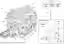
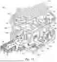


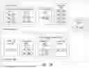
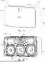
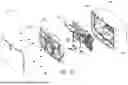


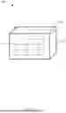

Sources:
- United States Patent and Trademark Office - verify current appl. status at the USPTO↗
Recent applications in this class:
- » 20260147527 2026-05-28
METHOD AND DEVICE FOR MANAGING CODEC CONFIGURATION OF BROADCAST AUDIO STREAM - » 20260147525 2026-05-28
AUDIO DEVICE AND CONTROL METHOD - » 20260147524 2026-05-28
SYSTEM AND METHOD FOR INTERFACING WITH AUDIO PLAYBACK DEVICES - » 20260140691 2026-05-21
MICROPHONE HUB AND METHOD OF OPERATING A MICROPHONE HUB - » 20260140690 2026-05-21
SYSTEMS AND METHODS FOR DYNAMIC INTEGRATION OF PORTABLE AUDIO DEVICES IN VEHICLES - » 20260133750 2026-05-14
SYSTEMS AND METHODS FOR AUDIO TRANSPORT - » 20260133749 2026-05-14
CALIBRATION ASSISTANCE - » 20260126947 2026-05-07
HEIGHT AUDIO ADJUSTMENT BASED ON LISTENING ENVIRONMENT CHARACTERISTICS - » 20260126946 2026-05-07
Multiple-Device Setup - » 20260119111 2026-04-30
PROCESSING AUDIO INPUTS TO PRODUCE TACTILE OUTPUTS