AEROSOL GENERATING ARTICLE AND AEROSOL GENERATING SYSTEM
US20260150892A1
2026-06-04
19/459,241
2026-01-26
Smart Summary: An aerosol generating product has three main parts: a medium section, a functional section, and a filtering section, all connected in a line. The medium section has holes that allow air to pass through, helping to create the aerosol. The functional section also has its own air holes for further processing. The filtering section includes additional holes to ensure the aerosol is clean and safe to use. There is also a system designed to work with this aerosol generating product. 🚀 TL;DR
Abstract:
An aerosol generating product is provided. The aerosol generating product includes a medium section, a functional section, and a filtering section which are sequentially arranged in a first direction; the medium section, the functional section, and the filtering section are all of an integrated structure; at least one first air passage hole is formed inside the medium section; at least one second air passage hole is formed inside the functional section; and at least one third air passage hole is formed inside the filtering section. An aerosol generating system is also provided.
Inventors:
- Jun NI 29 🇨🇳 Shenzhen, China
- Wenfeng Li 14 🇨🇳 Shenzhen, China
- Jianguo TANG 36 🇨🇳 Shenzhen, China
- Zutao JIN 18 🇨🇳 Shenzhen, China
- Xuezhi DAI 5 🇨🇳 Shenzhen, China
- Mengyang HU 5 🇨🇳 Shenzhen, China
Applicant:
Interested in similar patents?
Get notified when new applications in this technology area are published.
Classification:
A24D1/04 » CPC further
Cigars; Cigarettes with mouthpieces or filter-tips
A24D3/04 » CPC main
Tobacco smoke filters, e.g. filter-tips, filtering inserts; Filters specially adapted for simulated smoking devices; Mouthpieces for cigars or cigarettes Tobacco smoke filters characterised by their shape or structure
Description
CROSS-REFERENCE TO RELATED APPLICATIONS
This application is a continuation of International Patent Application No. PCT/CN2024/102559 filed on Jun. 28, 2024, which is filed based on and claims priority to Chinese patent application No. 202310930086.7 filed on Jul. 26, 2023. The disclosures of the applications are hereby incorporated by reference in their entireties.
BACKGROUND
This section is intended to provide background or context for implementations of the disclosure as recited in the claims. Descriptions here are not recognized as the related art just because it is included in this section.
Smoking-generating articles include a smoke-generating article forming aerosols by ignition and a smoke-generating article forming aerosols by Heated Not Burn (HNB), here in a typical HNB smoke-generating article, the smoking article contains a functional segment and an aerosol generating substrate which may evaporate when it is heated to generate aerosols, the functional segment cooperates with the aerosol generating substrate to achieve smoking the aerosols, the aerosol generating substrate is heated by an external heat source to an extent where the aerosol generating substrate is heated just enough to emit fragrance, the aerosol generating substrate does not burn, instead carries an atomizing agent, and the atomizing agent is released by heating at a high temperature during usage, to form smoke.
In the related art, there are quite different structures among the aerosol generating substrate, the filter segment and the functional segment, for example, the aerosol substrate is formed by wrapping shredded tobacco materials together, the filter segment is made of materials such as cellulose acetate or the like, the dispersed structure has an unstable porosity, which affects consistency of Resistance To Draw (RTD) of the smoke-generating article; furthermore, the functional segment is for example made of materials of which phase change or deformation occurs easily, the functional segment may block a portion of an air channel after the functional segment is deformed and melted by heat, which also affects consistency of the RTD of the smoke-generating article.
SUMMARY
The disclosure relate to the technical field of smoke-generating articles, and in particular to an aerosol generating article and an aerosol generating system, which may improve consistency of the RTD.
According to a first aspect of the disclosure, there is provided an aerosol generating article, the aerosol generating article includes a substrate segment, a functional segment and a filter segment sequentially arranged in a first direction, each of the substrate segment, the functional segment and the filter segment is provided in an integral structure.
The substrate segment is provided with at least one first air channel hole at interior thereof, and the first air channel hole passes through at least one end of the substrate segment in the first direction; the functional segment is provided with at least one second air channel hole at interior thereof, and the second air channel hole passes through at least one end of the functional segment in the first direction; the filter segment is provided with at least one third air channel hole at interior thereof, and the third air channel hole passes through at least one end of the filter segment in the first direction.
In an implementation, the substrate segment, the functional segment and the filter segment may be in a separable structure.
In an implementation, the substrate segment may be provided with at least one first air channel hole at interior thereof, and the first air channel hole passes through at least one end of the substrate segment in the first direction.
In an implementation, the functional segment may be provided with at least one second air channel hole at interior thereof, and the second air channel hole passes through at least one end of the functional segment in the first direction.
In an implementation, the filter segment may be provided with at least one third air channel hole at interior thereof, and the third air channel hole passes through at least one end of the filter segment in the first direction.
In an implementation, on a plane perpendicular to the first direction of the aerosol generating article, a sum of cross-sectional areas of all third air channel holes may be less than a sum of cross-sectional areas of all second air channel holes.
In an implementation, on the plane perpendicular to the first direction of the aerosol generating article, the cross-sectional area of each third air channel hole may be less than or equal to the cross-sectional area of each second air channel hole; or, a hydrodynamic diameter of each third air channel hole may be less than or equal to a hydrodynamic diameter of each second air channel hole.
In an implementation, the number of the third air channel holes may be equal to or greater than the number of the second air channel holes.
In an implementation, on a plane perpendicular to the first direction of the aerosol generating article, a sum of cross-sectional areas of all second air channel holes may be equal to or greater than a sum of cross-sectional areas of all first air channel holes.
In an implementation, on the plane perpendicular to the first direction of the aerosol generating article, the cross-sectional area of each second air channel hole may be equal to or greater than the cross-sectional area of each first air channel hole; or, a hydrodynamic diameter of each second air channel hole may be equal to or greater than a hydrodynamic diameter of each first air channel hole.
In an implementation, the number of the second air channel holes may be less than or equal to the number of the first air channel holes.
In an implementation, on a plane perpendicular to the first direction of the aerosol generating article, a sum of cross-sectional areas of all second air channel holes may be less than a sum of cross-sectional areas of all first air channel holes.
In an implementation, on the plane perpendicular to the first direction of the aerosol generating article, the cross-sectional area of each second air channel hole may be less than the cross-sectional area of each first air channel hole.
In an implementation, a hydrodynamic diameter of each second air channel hole may be less than a hydrodynamic diameter of each first air channel hole.
In an implementation, the number of the second air channel holes may be greater than the number of the first air channel holes.
In an implementation, there may be multiple first air channel holes, and the multiple first air channel holes are uniformly distributed in the substrate segment.
In an implementation, there may be multiple second air channel holes, and the multiple second air channel holes are uniformly distributed in the functional segment.
In an implementation, there may be multiple third air channel holes, and the multiple third air channel holes are uniformly distributed in the filter segment.
In an implementation, the functional segment may be provided with a central air channel at interior thereof, the central air channel passes through two ends of the functional segment in the first direction, there are multiple second air channel holes, and the second air channel holes are arranged at intervals on a circumferential side of the central air channel.
In an implementation, the aerosol generating article may be provided with at least one cavity at interior thereof.
In an implementation, the functional segment may be a cooling segment.
In an implementation, the substrate segment and the functional segment may be arranged at an interval there-between, to define the cavity.
In an implementation, the filter segment and the functional segment may be arranged at an interval there-between, to define the cavity.
In an implementation, the substrate segment may be provided with the cavity at least at an end away from the functional segment.
In an implementation, the filter segment may be provided with the cavity at least at an end away from the functional segment.
In an implementation, two ends of the functional segment in the first direction may be in contact with the substrate segment and the filter segment respectively.
In an implementation, the substrate segment, the functional segment and the filter segment may be cylinders with the same outer diameter and arranged coaxially, and the first direction is an axial direction of the substrate segment, the functional segment and the filter segment.
According to a second aspect of the disclosure, there is provided an aerosol generating system, the aerosol generating system includes an aerosol generating device and the aerosol generating article as described above, the aerosol generating device includes a heating element, and the heating element is configured to heat the substrate segment to generate aerosols.
An embodiment of the disclosure provides an aerosol generating article, the aerosol generating article includes a substrate segment, a functional segment and a filter segment sequentially arranged in a first direction, the substrate segment generates aerosols when it is heated, the functional segment achieves supporting and cooling functions, and the filter segment is configured to filter the aerosols flowing through the functional segment.
Each of the substrate segment, the functional segment and the filter segment of the aerosol generating article according to the embodiment of the disclosure is provided in an integral structure.
BRIEF DESCRIPTION OF THE DRAWINGS
FIG. 1 is a schematic structural diagram of an aerosol generating article according to an embodiment of the disclosure.
FIG. 2 is a cross-sectional view of the aerosol generating article shown in FIG. 1, here dashed arrows indicate a flow direction of airflow in the aerosol generating article.
FIG. 3 is a schematic cross-sectional view of an aerosol generating article according to a second embodiment of the disclosure.
FIG. 4 is a schematic cross-sectional view of an aerosol generating article according to a third embodiment of the disclosure.
FIG. 5 is a schematic cross-sectional view of an aerosol generating article according to a fourth embodiment of the disclosure.
FIG. 6 is a schematic cross-sectional view of an aerosol generating article according to a fifth embodiment of the disclosure.
FIG. 7 is a schematic cross-sectional view of an aerosol generating article according to a sixth embodiment of the disclosure.
FIG. 8 is a schematic cross-sectional view of an aerosol generating article according to a seventh embodiment of the disclosure.
FIG. 9 is a schematic cross-sectional view of an aerosol generating article according to an eighth embodiment of the disclosure.
FIG. 10 is a schematic cross-sectional view of an aerosol generating article according to a ninth embodiment of the disclosure.
FIG. 11 is a schematic cross-sectional view of an aerosol generating article according to a tenth embodiment of the disclosure.
FIG. 12 is a schematic cross-sectional view of an aerosol generating article according to an eleventh embodiment of the disclosure.
FIG. 13 is a schematic cross-sectional view of an aerosol generating article according to a twelfth embodiment of the disclosure.
DETAILED DESCRIPTION
It should be noted that embodiments of the disclosure and technical features in the embodiments may be combined with each other without conflict, and detailed descriptions in specific implementations should be understood as explanatory descriptions of the purpose of the disclosure, and should not be considered as undue limitation on the disclosure.
In descriptions of the disclosure, an orientation or position relationship of “first direction” is based on an orientation or position relationship shown in FIG. 1 and FIG. 2, and it should be understood that these orientation terms are only intended to facilitate describing the disclosure and simplifying the descriptions, rather than indicating or implying that a referred device or element must have a specific orientation or must be configured and operated in a specific orientation, and thus cannot be understood as limitation on the disclosure.
An embodiment of the disclosure provides an aerosol generating article, with reference to FIG. 1 to FIG. 13, the aerosol generating article includes a substrate segment 10, a functional segment 20 and a filter segment 30 sequentially arranged in a first direction. That is, the functional segment 20 is located between the filter segment 30 and the substrate segment 10, and the functional segment 20 may be configured to achieve supporting and/or cooling and/or adjusting Resistance To Draw (RTD).
Specifically, with reference to FIG. 2 and FIG. 3, two ends of the functional segment 20 in the first direction are in contact with the substrate segment 10 and the filter segment 30 respectively; at this time, the functional segment 20 may play a role of supporting the substrate segment 10 and the filter segment 30, to increase an overall strength of the aerosol generating article; furthermore, since the functional segment 20 is provided with second air channel holes 20a at interior thereof, the functional segment 20 may play a role of adjusting RTD; furthermore, aerosols generated by the substrate segment 10 pass through a certain length of the functional segment 20, temperature of the aerosols may be reduced; that is, in this implementation, the functional segment 20 plays a role of supporting, cooling and adjusting the RTD simultaneously.
With reference to FIG. 4, the functional segment 20 is spaced apart from each of the substrate segment 10 and the filter segment 30, and at this time, the functional segment mainly plays a role of cooling and adjusting the RTD. It may be understood that in other implementations, the functional segment 20 may also mainly play a role of supporting and adjusting the RTD, which is not limited to in the embodiment of the disclosure.
It should be noted that the filter segment 30 is configured to filter the aerosols, and it may be understood that since the aerosols flow through the filter segment, the filter segment also achieves a function of further cooling the aerosols.
It should be noted that the aerosol generating article 100 generates aerosols by the substrate segment 10, and the functional segment 20 is not configured to generate aerosols.
It should be noted that the aerosol generating article 100 according to the embodiment of the disclosure may be applicable to a scenario where it is smoked by ignition, or may be applicable to a scenario where it is smoked by Heated Not Burn (HNB). In the embodiment of the disclosure, descriptions are made by taking an example that the aerosol generating article 100 is applicable to the scenario where it is smoked by HNB.
The aerosol generating article 100 is intended to use with an aerosol generating device.
The substrate segment 10 is configured to generate aerosols when it is heated, to allow a user to smoke the aerosols.
In the embodiment of the disclosure, the substrate segment 10 is in a substantially columnar shape. The columnar shape may be a cylindrical shape (that is, a cross-sectional shape thereof is a circular shape), a prismatic shape (that is, a cross-sectional shape thereof is a polygonal shape), an elliptical cylindrical shape (that is, a cross-sectional shape thereof is an elliptical shape) or the like, which is not limited here.
Exemplarily, the substrate segment 10, the functional segment 20 and the filter segment 30 are in a separable structure, all of the substrate segment 10, the functional segment 20 and the filter segment 30 are not connected together by mechanical or physical structures or adhesives there-between, while two of the substrate segment 10, the functional segment 20 and the filter segment 30 may be in contact with each other, that is, the substrate segment 10, the functional segment 20 and the filter segment 30 are in a combined structure, therefore different substrate segments 10 may be reasonably matched with different functional segments 20 and different filter segments 30 to meet customer's requirements for different RTDs and temperatures.
Each of the substrate segment 10, the functional segment 20 and the filter segment 30 is provided in an integral structure, and in an implementation, the substrate segment 10 is provided in an integral structure formed by extrusion, the functional segment 20 is also provided in an integral structure formed by extrusion, and the filter segment 30 is also provided in an integral structure formed by extrusion. Compared to the related art where the substrate segment, the functional segment and the filter segment are produced and manufactured by using different processing technologies, the substrate segment 10, the functional segment 20 and the filter segment 30 are produced and manufactured by using the same processing technology, and different substrate segments 10, functional segments 20 and filter segments 30 may be manufactured by one production line, which reduces input cost of manufacturing them and improves production efficiency of the aerosol generating article.
In other implementations, each of the substrate segment 10 and the filter segment may also be provided in an integral structure formed by injection molding, die-casting or other processes respectively.
Exemplarily, with reference to FIG. 2 to FIG. 13, the substrate segment 10 is provided with at least one first air channel hole 10a at interior thereof, and the first air channel hole 10a passes through at least one end of the substrate segment 10 in the first direction. That is, the first air channel hole 10a extends in the first direction of the substrate segment 10.
It should be noted that the first air channel hole 10a is not limited in terms of its number, and there may be one first air channel hole 10a or multiple first air channel holes 10a.
It should be noted that “multiple” mentioned in the embodiment of the disclosure refers to a number of two or more.
When it is mentioned that the first air channel hole 10a passes through at least one end of the substrate segment 10 in the first direction, it means that the first air channel hole 10a may pass through opposite ends of the substrate segment 10 in the first direction (with reference to FIG. 2 to FIG. 13), and an airflow may flow from an end of the substrate segment 10 in the first direction to another end of the substrate segment 10 in the first direction through the first air channel hole 10a.
Of course, it may also mean that an end of the first air channel hole 10a passes through an end surface of the substrate segment 10 in the first direction, and another end of the first air channel hole 10a may be a blind end. Each first air channel hole 10a may pass through the same end of the substrate segment 10 in the first direction. In other implementations, a portion of the first air channel holes 10a may pass through an end of the substrate segment 10 in the first direction, and another portion of the first air channel holes 10a may pass through another end of the substrate segment 10 in the first direction.
It may be understood that compared to the first air channel hole 10a passing through an end of the substrate segment 10 in the first direction, it is more beneficial to reduce the user's RTD upon smoking the article by the first air channel hole 10a passing through two ends of the substrate segment 10 in the first direction.
The first air channel hole 10a may increase a surface area of the substrate segment 10, facilitate heat transfer and improve heating efficiency. Aerosols in the first air channel hole 10a is transported to a smoking end with an action of a negative pressure for smoking, the first air channel hole 10a may reduce the user's RTD upon smoking the article and improve the user's experience. It should be noted that the RTD is positively correlated to flow resistance of the aerosols, then the smaller the flow resistance of the aerosols in the substrate segment 10, the smaller the RTD experienced by the user, and the greater the flow resistance of the aerosols in the substrate segment 10, the greater the RTD experienced by the user.
It should be noted that the substrate segment 10 is formed with micropores, and the micropores are communicated with each other and form a micro-air channel communicated with the first air channel hole 10a. That is, the micro-air channel is communicated with the first air channel hole 10a, and since the micro-air channel is formed by communication between the micropores, the micropores are communicated with the channel 10a. Furthermore, it may be understood that the communication between the micropores may be that: a portion of the micropores are communicated with each other, and another portion of the micropores are not communicated with each other; or, all the micropores may be communicated with each other. For example, in an embodiment where the substrate segment 10 is a particle-combined body, gaps between particles constitute the micropores. A size of each of the micropores is determined by the gaps between the particles.
The first air channel hole 10a and the micro-air channel may increase the surface area of the substrate segment 10, facilitate heat transfer and improve heating efficiency. The substrate of the substrate segment 10 releases aerosols when it is heated, the aerosols are collected to the first air channel hole 10a through the micro-air channel or gaps between wall materials, aerosols released by an atomized substrate exposed to the first air channel hole 10a (i.e., an atomized substrate located on an inner wall surface of the air channel hole) may be directly released to the first air channel hole 10a, aerosols from adjacent first air channel holes 10a may also circulate between the first air channel holes 10a through the micro-air channel and may be transported to the smoking end with an action of a negative pressure for smoking.
Exemplarily, with reference to FIG. 2 to FIG. 13, the functional segment 20 is provided with at least one second air channel hole 20a at interior thereof, and the second air channel hole 20a passes through at least one end of the functional segment 20 in the first direction. That is, the second air channel hole 20a extends in the first direction of the functional segment 20.
The functional segment 20 is provided in an integral structure formed by extrusion, the functional segment 20 is provided with at least one second air channel hole 20a at interior thereof, and the second air channel hole 20a passes through at least one end of the functional segment 20 in the first direction, the functional segment 20 with a porous structure formed in this manner plays a role of supporting and/or cooling and/or adjusting the RTD.
With arrangement of the second air channel hole 20a, when the aerosols pass through the functional segment 20, the aerosols may flow through the second air channel hole 20a, which is beneficial to cool the aerosols. Furthermore, it facilitates adjusting the RTD by controlling design parameters of the second air channel hole 20a.
It should be noted that the second air channel hole 20a is not limited in terms of its number, and there may be one second air channel hole 20a or multiple second air channel
holes 20a.
When it is mentioned that the second air channel hole 20a passes through at least one end of the functional segment 20 in the first direction, it means that the second air channel hole 20a may pass through opposite ends of the functional segment 20 in the first direction (with reference to FIG. 2 to FIG. 13), and an airflow may flow from an end of the functional segment 20 in the first direction to another end of the functional segment 20 in the first direction through the second air channel hole 20a.
Of course, it may also mean that an end of the second air channel hole 20a passes through an end surface of the functional segment 20 in the first direction, and another end of the second air channel hole 20a may be a blind end. Each second air channel hole 20a may pass through the same end of the functional segment 20 in the first direction. In other implementations, a portion of the second air channel holes 20a may pass through an end of the functional segment 20 in the first direction, and another portion of the second air channel holes 20a may pass through another end of the functional segment 20 in the first direction.
It may be understood that compared to the second air channel hole 20a passing through an end of the functional segment 20 in the first direction, it is more beneficial to reduce the user's RTD upon smoking the article by the second air channel hole 20a passing through two ends of the functional segment 20 in the first direction.
It should be noted that the functional segment 20 molded by extrusion is also formed with micropores at interior thereof, that is, gaps between components of the functional segment 20 constitute micropores, and the micropores are communicated with each other and form a micro-air channel communicated with the second air channel hole 20a. When the aerosols pass through the functional segment 20, a portion of the aerosols may flow through the second air channel hole 20a, another portion of the aerosols may flow through the micro-air channel, and the aerosols stay for a long time when they flow through the micro-air channel, which is beneficial to cool the aerosols. Furthermore, there is a large flow resistance of the aerosols when they flow through the micro-air channel, which may increase the RTD, that is, it is beneficial to achieve adjustment of the RTD through the functional segment 20.
Exemplarily, with reference to FIG. 2 to FIG. 13, the filter segment 30 is provided with at least one third air channel hole 30a at interior thereof, and the third air channel hole 30a passes through at least one end of the filter segment 30 in the first direction. That is, the third air channel hole 30a extends in the first direction of the filter segment 30.
The filter segment 30 is provided in an integral structure formed by extrusion, the filter segment 30 is provided with at least one third air channel hole 30a at interior thereof, and the third air channel hole 30a passes through at least one end of the filter segment 30 in the first direction, the filter segment 30 with a porous structure formed in this manner plays a role of adjusting RTD of a cigarette and targeted filtering harmful components of the aerosols (for example, the harmful components are carbon monoxide, tar, etc.).
With arrangement of the third air channel hole 30a, a contact area between the filter segment 30 and an airflow is increased, such that the filter segment 30 may adsorb impurities entrained in the airflow better, it improves a filtering effect, thereby improving the user's experience upon using the article. Furthermore, it facilitates adjusting the RTD by controlling design parameters of the third air channel hole 30a.
It should be noted that the third air channel hole 30a is not limited in terms of its number, and there may be one third air channel hole 30a or multiple third air channel holes 30a.
When it is mentioned that the third air channel hole 30a passes through at least one end of the filter segment 30 in the first direction, it means that the third air channel hole 30a may pass through opposite ends of the filter segment 30 in the first direction (with reference to FIG. 2 to FIG. 13), and an airflow may flow from an end of the filter segment 30 in the first direction to another end of the filter segment 30 in the first direction through the third air channel hole 30a.
Of course, it may also mean that an end of the third air channel hole 30a passes through an end surface of the filter segment 30 in the first direction, and another end of the third air channel hole 30a may be a blind end. Each third air channel hole 30a may pass through the same end of the filter segment 30 in the first direction. In other implementations, a portion of the third air channel holes 30a may pass through an end of the filter segment 30 in the first direction, and another portion of the third air channel holes 30a may pass through another end of the filter segment 30 in the first direction.
It may be understood that compared to the third air channel hole 30a passing through an end of the filter segment 30 in the first direction, it is more beneficial to reduce the user's RTD upon smoking the article by the third air channel hole 30a passing through two ends of the filter segment 30 in the first direction.
It should be noted that the filter segment 30 molded by extrusion is also formed with micropores at interior thereof, that is, gaps between components of the filter segment 30 constitute micropores, and the micropores are communicated with each other and form a micro-air channel communicated with the third air channel hole 30a. When the aerosols pass through the filter segment 30, a portion of the aerosols may flow through the third air channel hole 30a, another portion of the aerosols may flow through the micro-air channel, and there is a large flow resistance of the aerosols when they flow through the micro-air channel, thereby achieving a filtering function; furthermore, it may also increase the RTD, that is, it is beneficial to achieve adjustment of the RTD through the filter segment 30.
It should be noted that the first air channel hole 10a, the second air channel hole 20a and the third air channel hole 30a as described above belong to holes in a macroscopic sense, the micropores belong to holes in a microscopic sense, and cross-sectional areas of the first air channel hole 10a, the second air channel hole 20a and the third air channel hole 30a are much greater than those of the micropores. A size of each of the micropores is determined by gaps between the particles.
Exemplarily, the substrate segment 10 is a particle-combined body, which is also referred to as a powder-combined body, it is a kind of recombinant tobacco substrate, such as a recombinant tobacco substrate containing a smoke-generating agent, tobacco or other components. The substrate segment 10 is provided in an integral structure, such as an integral structure that may be molded by an extrusion process. “molded by extrusion” refers to a processing method by which a mixture of raw materials is fed into an extruder, the materials are pushed forward by screws with an action of a barrel of the extruder with the screws, and continuously pass through a mold of a discharge port of the extruder to form products or semi-finished products in various cross-sectional shapes. The substrate molded by extrusion is in a strip-shaped structure. In this way, the substrate segment 10 presents an integral substrate after the substrate segment 10 is heated for smoking or heating of the substrate segment 10 is stopped, and a phenomenon of disintegration and falling down does not occur easily, which solves problems occurred to the substrate segment 10 made of thin sheets, filamentous or dispersed particles in the related art, for example, the thin sheets loosen and fall off, filamentous components fall off, particle components fall off, and it is difficult to clean the substrate segment, as well as a problem of non-uniform components.
Exemplarily, with reference to FIG. 1 to FIG. 13, the aerosol generating article 100 includes a wrapping layer 40, and the wrapping layer 40 wraps around outer circumferences of the substrate segment 10, the functional segment 20 and the filter segment 30.
The wrapping layer 40 may play a role of protecting the substrate segment 10 to a certain extent, reduce a surface area of the substrate segment 10 exposed to the external environment directly, thereby reducing a probability of the substrate segment 10 becoming damp and deteriorated by contacting with the air, while reducing a probability of the substrate segment 10 becoming contaminated by contacting with other components in the aerosol generating device.
It should be noted that the substrate segment 10 and the wrapping layer 40 may be provided in an integral structure. That is, the substrate segment 10 and the wrapping layer 40 are different parts of an integral structure. In this way, on one hand, relative positions of the substrate segment 10 and the wrapping layer 40 are fixed, which may reduce a probability of separation of the substrate segment 10 from the wrapping layer 40 due to temperature variation, vibration or other factors during usage of the aerosol generating article 100; on the other hand, the substrate segment 10 and the wrapping layer 40 may be prepared simultaneously, thereby reducing manufacturing steps and improving production efficiency.
For example, the integral structure of the substrate segment and the wrapping layer 40 is formed by a co-extrusion process.
Of course, the substrate segment 10 and the wrapping layer 40 may also be in a split-type structure.
An embodiment of the disclosure further provides an aerosol generating system, the aerosol generating system includes an aerosol generating device and the aerosol generating article according to the embodiment of the disclosure, the aerosol generating device includes a heating element (not shown), and the heating element is configured to heat the substrate segment 10 to generate aerosols.
Specifically, the aerosol generating device includes a housing and a power supply assembly arranged in the housing, the housing is provided with an accommodation cavity, a power output part of the power supply assembly is arranged in the accommodation cavity or around a side wall of the accommodation cavity. When a part of the aerosol generating article 100 corresponding to a range of the first direction where the substrate segment 10 is located is inserted into the accommodation cavity, the power output part transmits power to a heating element in a contact or non-contact manner, and the heating element generates heat by receiving energy from the outside, thereby heating the substrate segment 10 to generate aerosols.
In the embodiment of the disclosure, the first direction does not specifically refer to a direction in which the substrate segment 10 presents a longest outer contour. Specifically, with reference to FIG. 1 and FIG. 2, a direction in which the aerosol generating article 100 is inserted into the accommodation cavity and a direction in which the aerosol generating article 100 is taken out of the accommodation cavity are both parallel to the first direction. A length of the substrate segment 10 in the first direction may be longer than, shorter than or the same as lengths of the substrate segment 10 in other directions.
For example, when the outer contour of the substrate segment 10 is in a cylindrical shape, the first direction is an axial direction of the substrate segment 10, and it should be noted that even when a length of the substrate segment 10 in the axial direction is less than a diameter of the substrate segment 10, the first direction of the substrate segment 10 is still the axial direction. For another example, when the outer contour of the substrate segment 10 is in a rectangular parallelepiped shape, the first direction is still the direction as defined above, that is, the direction in which the aerosol generating article 100 is put into or taken out of the accommodation cavity, the first direction of the substrate segment 10 may be any one of a length direction, a width direction and a height direction of the rectangular parallelepiped shape.
An embodiment of the disclosure provides an aerosol generating article, the aerosol generating article 100 includes a substrate segment 10, a functional segment 20 and a filter segment 30 sequentially arranged in a first direction, the substrate segment 10 generates aerosols when it is heated, the functional segment 20 plays a role of supporting and/or cooling and/or adjusting the RTD, the filter segment 30 is configured to filter the aerosols flowing through the functional segment 20, and it may be understood that since the aerosols flow through the filter segment 30, the filter segment 30 also achieves a function of further cooling the aerosols.
Each of the substrate segment 10, the functional segment 30 and the filter segment 30 of the aerosol generating article 100 according to the embodiment of the disclosure is provided in an integral structure. With at least one first air channel hole 10a provided at interior of the substrate segment 10, and with at least one third air channel hole 30a provided at interior of the filter segment 30, it is beneficial to control porosities of the substrate segment 10 and the filter segment 30; with control of porosities of the substrate segment 10 and the filter segment 30, it is beneficial to adjust RTD of the aerosol generating article 100; with the functional segment 20 configured in an integral structure provided with the second air channel hole 20a, it improves high temperature-resistant performance of the functional segment 20, thereby improving structural stability of the functional segment 20, the functional segment 20 is not easily deformed and melted after it is heated, which may improve a situation of blocking the air channel to a certain extent, and it is further beneficial to adjust the RTD of the aerosol generating article 100, thereby improving the user's experience upon using the article. Furthermore, each of the substrate segment 10, the functional segment 20 and the filter segment 30 is provided in an integral structure, and the integral structure has a relatively stable porosity, therefore consistency of the RTD of the aerosol generating article 100 may be improved.
On the other hand, the filter segment 30 is provided in an integral structure formed by extrusion, which is beneficial to achieve targeted filtration of the aerosols and improve on-demand delivery and transfer of effective components of the aerosols. Furthermore, fragrance components may be used or added to components of the functional segment and the filter segment, to achieve a function of carrying fragrance by the functional segment and the filter segment, and release of the fragrance components from the functional segment and the filter segment is promoted by heat of the aerosols during usage, to increase sensory richness.
It should be noted that specific types of the functional segment 20 are not limited here, as long as the functional segment 20 may play a role of supporting and/or cooling and/or adjusting the RTD. Exemplarily, the functional segment 20 is a cooling segment.
Specific components of the substrate segment 10 are not limited here. Exemplarily, in an embodiment, the substrate segment 10 may include a plant component, an adjuvant component, a smoke-generating agent component, an adhesive component, a fragrant component, etc.
The plant component is configured to generate aerosols when it is heated. The adjuvant component is configured to provide a skeleton support for the plant component. The smoke-generating agent component is configured to generate smoke when it is heated. The adhesive component is configured to bond various raw material components. The fragrant component is configured to provide characteristic fragrance. In this way, the plant component and the smoke-generating agent component may ensure a generation amount of the aerosols, while the fragrant component may improve release of fragrance during smoking and improve the user's experience. The adjuvant component may not only improve fluidity of a mixed material, but also enable the substrate segment 10 to have a porous structure to facilitate extraction and flow of the aerosols. The adhesive component ensures that the plant component, the adjuvant component or the like constitute a stable mixture, to avoid a loose structure.
Exemplarily, the plant component may be a combination of one or more of powders formed by crushing treatment of leaf tobacco raw materials, leaf tobacco fragments, tobacco stems, tobacco fine wastes, fragrant plants, etc. The plant component is a core source of fragrance, endogenous substances in the plant component may produce a sense of physiological satisfaction for the user, the endogenous substances such as alkaloid enter human blood and promote the pituitary gland to produce dopamine, thereby obtaining the sense of physiological satisfaction.
Exemplarily, the adjuvant component may be a combination of one or more of an inorganic filler, a lubricant and an emulsifier. The inorganic filler includes a combination of one or more of ground calcium carbonate, precipitated calcium carbonate, zeolite, attapulgite, talc powder and diatomaceous earth. The inorganic filler may play a role of providing a skeleton support for the plant component, while the inorganic filler is also provided with micropores, which may improve a porosity of the substrate segment 10, thereby improving a release rate of the aerosols. The lubricant includes a combination of one or more of candelilla wax, carnauba wax, shellac, sunflower wax, rice bran, beeswax, stearic acid and palmitic acid. The lubricant may improve fluidity of powders of the plant component, reduce a friction force between the powders of the plant component, implement a more uniform overall density of distribution of the powders of the plant component, reduce a pressure required in a process of molding by extrusion, and reduce wear of the mold. The emulsifier includes a combination of one or more of polyglycerol fatty acid ester, Tween-80 and polyvinyl alcohol. The emulsifier may slow down loss of fragrant substances during storage to a certain extent, improve stability of the fragrant substances, and improve sensory quality of the article.
Exemplarily, the smoke-generating agent component may include a combination of one or more of monohydric alcohol (such as menthol); polyhydric alcohol (such as propylene glycol, glycerol, triethylene glycol, 1,3-butanediol, and tetraethylene glycol); esters of polyhydric alcohol (such as glycerol triacetate, triethyl citrate, glyceryl diacetate mixture, triethyl citrate, benzyl benzoate, glyceryl tributyrate); monocarboxylic acid; dicarboxylic acid; polycarboxylic acid (such as lauric acid, myristic acid) or aliphatic esters of polycarboxylic acid (such as dimethyl dodecanedioate, dimethyl tetradecanedioate, erythritol, 1,3-butanediol, tetraethylene glycol, triethyl citrate, propylene carbonate, ethyl laurate, Triactin, meso-erythritol, glyceryl diacetate mixture, diethyl suberate, triethyl citrate, benzyl benzoate, benzyl phenylacetate, ethyl vanillate, glyceryl tributyrate, ethyl laurate).
Exemplarily, the adhesive component is in moist and close contact with interfaces of component raw materials, to generate an intermolecular attraction force, thereby playing a role of bonding the component raw materials, such as powders, liquids, etc. The adhesive component may be extracted from a natural plant, and a non-ionized modified viscous polysaccharide, including a combination of one or more of tamarind polysaccharide, guar gum and modified cellulose (such as carboxymethyl cellulose). The adhesive is configured to bond the particles together such that it is not easy to loosen the particles, it also improves water resistance of the substrate segment 10 and is harmless to human body.
Exemplarily, the fragrant component is configured to provide characteristic fragrance, such as hay fragrance, roasted sweet fragrance, solid or liquid substances of nicotine. The fragrant component may include a combination of one or more of tobacco or other plants, extractions from fragrant plants, extractum, essential oils and absolute oils; the fragrant component may include monomeric fragrant substances, such as a combination of one or more of megastigmatrienone, neophytadiene, geraniol and nerol, etc.
Exemplarily, in some implementations, components of the functional segment 20 are the same as those of the substrate segment 10. That is, the functional segment 20 may be molded by extrusion from the same components as those of the substrate segment 10, which further improves production efficiency during manufacture.
In some other implementations, components of the functional segment 20 are different from those of the substrate segment 10. Specifically, the functional segment 20 is provided in an integral structure molded by extrusion from a combination of any one or more of inorganic materials (calcium carbonate, alumina, diatomaceous earth, calcined kaolin, etc.), polymeric materials (food-grade silicone, microcrystalline cellulose, konjac gum, starch, plant polysaccharide, etc.) and polymers (low-density polyethylene (LDPE), polypropylene (PP), thermoplastic elastomer (TPE), polylactic acid (PLA), TPE-modified PP, TPE-modified polyethylene (PE), etc.).
Exemplarily, in some implementations, components of the filter segment 30 are the same as those of the substrate segment 10. That is, the filter segment 30 may be molded by extrusion from the same components as those of the substrate segment 10, which further improves production efficiency during manufacture.
In some other implementations, components of the filter segment 30 are different from those of the substrate segment 10. Specifically, the filter segment 30 is provided in an integral structure molded by extrusion from a combination of any one or more of inorganic materials (calcium carbonate, alumina, diatomaceous earth, calcined kaolin, etc.), polymeric materials (food-grade silicone, microcrystalline cellulose, konjac gum, starch, plant polysaccharide, etc.) and polymers (LDPE, PP, TPE, PLA, TPE-modified PP, TPE-modified PE, etc.).
should be noted that the functional segment 20 achieves a function of adjusting the RTD. Specifically, the functional segment 20 may adjust the RTD by controlling parameters such as the number of the second air channel holes 20a of the functional segment 20, a hydrodynamic diameter of the second air channel hole 20a, etc.
In order to meet requirements for sensory characteristics such as implementation of natural and smooth smoking by the user during smoking, permeability of tobacco smoke, comfort or the like and improve the user's experience upon using the article, it needs to control a range of RTD of the aerosol generating article 100. It should be noted that the RTD is positively correlated to flow resistance of the aerosols, then the smaller the flow resistance of the aerosols in the aerosol generating article 100, the smaller the RTD experienced by the user, and the greater the flow resistance of the aerosols in the aerosol generating article 100, the greater the RTD experienced by the user.
It should be noted that for the filter segment 30, the RTD of the filter segment 30 may be adjusted by controlling parameters such as the number of the third air channel holes 30a of the filter segment 30, a hydrodynamic diameter of the third air channel hole 30a, a sum of cross-sectional areas of all the third air channel holes 30a, etc. For the functional segment 20, the RTD of the functional segment 20 may be adjusted by controlling parameters such as the number of the second air channel holes 20a of the functional segment 20, the hydrodynamic diameter of the second air channel hole 20a, a sum of cross-sectional areas of all the second air channel holes 20a, etc. For the substrate segment 10, the RTD of the substrate segment 10 may be adjusted by controlling parameters such as the number of the first air channel holes 10a of the substrate segment 10, a hydrodynamic diameter of the first air channel hole 10a, a sum of cross-sectional areas of all the first air channel holes 10a, etc.
Exemplarily, on a plane perpendicular to the first direction of the aerosol generating article 100, a sum of cross-sectional areas of all third air channel holes 30a is less than a sum of cross-sectional areas of all second air channel holes 20a. In this way, the RTD of the filter segment 30 may be less than that of the functional segment 20, which may increase the RTD of the aerosol generating article 100 while achieving the filtering function.
Exemplarily, in some implementations, with reference to FIG. 2 to FIG. 13, on the plane perpendicular to the first direction of the aerosol generating article 100, the cross-sectional area of each third air channel hole 30a is less than or equal to the cross-sectional area of each second air channel hole 20a. That is, a hydrodynamic diameter of each third air channel hole 30a is less than or equal to a hydrodynamic diameter of each second air channel hole 20a.
It may be understood that the third air channel hole 30a has a small hydrodynamic diameter, which has a certain effect of hindering flow of the aerosols, such that a portion of the aerosols passes through the micropores, it may increase the RTD of the filter segment 30 while achieving the filtering function, thereby increasing the RTD of the aerosol generating article 100. Furthermore, when there is a large number of third air channel holes 30a each with a small hydrodynamic diameter, it is more beneficial to filter the aerosols.
In the embodiment of the disclosure, the hydrodynamic diameter refers to a ratio of four times the area of a flow cross section of the hole to a perimeter thereof.
Exemplarily, in some implementations, the number of the third air channel holes 30a is equal to or greater than the number of the second air channel holes 20a. It may be understood that when there is a large number of third air channel holes 30a each with a small hydrodynamic diameter, it is more beneficial to achieve a filtering effect of the aerosols and increase the RTD of the aerosol generating article 100.
Exemplarily, in some implementations, with reference to FIG. 3, on a plane perpendicular to the first direction of the aerosol generating article 100, a sum of cross-sectional areas of all second air channel holes 20a is equal to or greater than a sum of cross-sectional areas of all first air channel holes 10a. That is, a porosity of the functional segment 20 is equal to or greater than that of the substrate segment 10, that is, the RTD of the functional segment 20 is less than or equal to that of the substrate segment 10. In this way, a residence time of the aerosols flowing through the functional segment 20 and a contact area between the aerosols and the functional segment 20 may be increased, thereby improving a cooling effect.
Exemplarily, in some implementations, with reference to FIG. 3, on the plane perpendicular to the first direction of the aerosol generating article 100, the cross-sectional area of each second air channel hole 20a is equal to or greater than the cross-sectional area of each first air channel hole 10a. That is, a hydrodynamic diameter of each second air channel hole 20a is equal to or greater than a hydrodynamic diameter of each first air channel hole 10a.
It may be understood that when the aerosols flow from the first air channel hole 10a of the substrate segment 10 to the second air channel hole 20a of the functional segment 20, an airflow channel becomes large, the residence time of the aerosols is increased, and the functional segment 20 is not heated any more, thereby achieving an effect of reducing temperature of the aerosols. Furthermore, since the hydrodynamic diameter of each second air channel hole 20a is equal to or greater than that of each first air channel hole 10a, the flow resistance of the aerosols is reduced when the aerosols flow from the first air channel hole 10a to the second air channel hole 20a, which is beneficial to extract the aerosols. Furthermore, the functional segment 20 is also provided with micropores, then when the aerosols flow through the functional segment 20, a portion of the aerosols may flow through the micropores, which further increases the residence time of the aerosols and thus is further beneficial to cool the aerosols.
It may be understood that when there is a small number of second air channel holes 20a each with a large hydrodynamic diameter, it is more beneficial to cool the aerosols. On the
plane perpendicular to the first direction of the aerosol generating article 100, the cross section of the functional segment 20 is consistent with that of the substrate segment 10, then when the hydrodynamic diameter of each second air channel hole 20a is greater than that of each first air channel hole 10a, the number of the second air channel holes 20a should be less than the number of the first air channel holes 10a. Exemplarily, the number of the second air channel holes 20a is less than or equal to the number of the first air channel holes 10a.
Exemplarily, in some other implementations, with reference to FIG. 2, on a plane perpendicular to the first direction of the aerosol generating article 100, a sum of cross-sectional areas of all second air channel holes 20a is less than a sum of cross-sectional areas of all first air channel holes 10a. That is, the porosity of the functional segment 20 is less than that of the substrate segment 10, that is, the RTD of the functional segment 20 is greater than that of the substrate segment 10. In this way, when the aerosols flow from the substrate segment 10 to the functional segment 20, the RTD of the aerosol generating article 100 may be increased, it may be ensured that it is easy to extract aerosols from interior of the substrate segment 10, the aerosols are released more uniformly and there is a high aerosol utilization, a burnt phenomenon of the substrate segment 10 does not occur easily in this case, while requirements for sensory characteristics such as implementation of natural and smooth smoking by the user during smoking, permeability of tobacco smoke, comfort or the like are met.
Exemplarily, in some other implementations, with reference to FIG. 2, on the plane perpendicular to the first direction of the aerosol generating article 100, the cross-sectional area of each second air channel hole 20a is less than the cross-sectional area of each first air channel hole 10a. That is, a hydrodynamic diameter of each second air channel hole 20a is less than a hydrodynamic diameter of each first air channel hole 10a.
It may be understood that when the aerosols flow from the first air channel hole 10a of the substrate segment 10 to the second air channel hole 20a of the functional segment 20, the airflow channel becomes small, that is, the RTD of the functional segment 20 is greater than that of the substrate segment 10, which is beneficial to increase the RTD of the aerosol generating article 100. Furthermore, the functional segment 20 is also provided with micropores, then when the aerosols flow through the functional segment 20, a portion of the aerosols may flow through the micropores, which further increases the flow resistance of the aerosols and thus is further beneficial to increase the RTD of the aerosol generating article 100.
It may be understood that when there is a large number of second air channel holes 20a each with a small hydrodynamic diameter, it is more beneficial to increase RTDs of the functional segment 20 and the aerosol generating article 100. On the plane perpendicular to the first direction of the aerosol generating article 100, the cross section of the functional segment 20 is consistent with that of the substrate segment 10, then when the hydrodynamic diameter of the second air channel hole 20a is less than that of the first air channel hole 10a, the number of the second air channel holes 20a should be greater than the number of the first air channel holes 10a. Exemplarily, in some other implementations, the number of the second air channel holes 20a is greater than the number of the first air channel holes 10a.
It should be noted that the shape of the second air channel hole 20a is not limited here. Exemplarily, on a plane perpendicular to the first direction of the aerosol generating article 100, a cross-sectional shape of the second air channel hole 20a is at least one of a circular shape (as shown in FIG. 4 and FIG. 9), an elliptical shape, a racetrack shape, a polygonal shape or a sector shape, here the polygonal shape includes a regular or irregular polygonal shape.
The racetrack shape refers to a shape similar to an athletics track, formed by connecting two semicircles and two parallel straight edges alternately.
It should be noted that the shape of the third air channel hole 30a is not limited here. Exemplarily, on a plane perpendicular to the first direction of the aerosol generating article 100, a cross-sectional shape of the third air channel hole 30a is at least one of a circular shape (as shown in FIG. 2 to FIG. 13), an elliptical shape, a racetrack shape, a polygonal shape or a sector shape, here the polygonal shape includes a regular or irregular polygonal shape.
Exemplarily, with reference to FIG. 4 to FIG. 13, the aerosol generating article 100 is provided with at least one cavity 100a at interior thereof. It should be noted that the number of cavities 100a is not limited here, that is, there may be one cavity 100a or multiple cavities 100a.
It should be noted that specific positions and formation methods of the cavity 100a are not limited here, for example, the cavity 100a may be formed between any two of the substrate segment 10, the functional segment 20 and the filter segment 30, or the cavity 100a may be formed at an end of the substrate segment 10 away from the functional segment 20, or the cavity 100a may be formed at an end of the filter segment 30 away from the functional segment 20.
With a combined structure of cavities 100a arranged at different positions, a flow path of the aerosols may be increased, the airflow channel may be increased; with technical principles such as heat exchange or the like, and with a structure where the cavities 100a are combined as required, advantageous effects may be achieved in aspects of improving formation, buffering and cooling of the aerosols, etc.
Exemplarily, in some implementations, with reference to FIG. 5 and FIG. 10, the substrate segment 10 and the functional segment 20 are arranged at an interval there-between, to define the cavity 100a. That is, the substrate segment 10 and the functional segment 20 are arranged at an interval there-between, and form the cavity 100a by enclosing the cavity 100a together with the wrapping layer 40 wrapping around circumferential sides of the substrate segment 10 and the functional segment 20. It may be understood that with the cavity 100a formed between the substrate segment 10 and the functional segment 20, the aerosols generated by heating the substrate segment 10 may flow into the cavity 100a, and with arrangement of the cavity 100a, it may buffer the aerosols generated by the substrate segment 10, which may be beneficial to extract the aerosols and improve utilization of the substrate segment 10. Furthermore, with arrangement of the cavity 100a, it may increase a contact area between an airflow flowing out of the substrate segment 10 and the aerosol generating article 100, thereby achieving a better cooling effect.
Exemplarily, in some implementations, with reference to FIG. 6 and FIG. 9, the functional segment 20 and the filter segment 30 are arranged at an interval there-between, to define the cavity 100a. That is, the functional segment 20 and the filter segment 30 are arranged at an interval there-between, and form the cavity 100a by enclosing the cavity 100a together with the wrapping layer 40 wrapping around circumferential sides of the functional segment 20 and the filter segment 30. It may be understood that with the cavity 100a formed between the functional segment 20 and the filter segment 30, the aerosols generated by heating the substrate segment 10 may flow into the functional segment 20, and then flow into the cavity 100a to buffer the aerosols. Therefore, the flow path of the aerosols may be increased during transportation of the aerosols, thereby achieving a quick cooling effect; furthermore, with arrangement of the cavity 100a, it may also buffer the aerosols generated by the substrate segment 10.
It should be noted that in some other embodiments, with reference to FIG. 4, FIG. 11 to FIG. 13, a cavity 100a is provided between the substrate segment 10 and the functional segment 20, and another cavity 100a is provided between the functional segment 20 and the filter segment 30. The cavity 100a provided in the embodiment achieves functions of buffering and cooling the aerosols, and it is beneficial to extract the aerosols quickly. Furthermore, under a premise of giving priority to ensuring the function of buffering the aerosols, a cavity 100a is provided between the substrate segment 10 and the functional segment 20, and another cavity 100a is provided between the functional segment 20 and the filter segment 30, that is, the function of buffering the aerosols and extraction rate of the aerosols are further improved with a structure where the cavities 100a are combined alternately.
Exemplarily, in some implementations, with reference to FIG. 7 and FIG. 13, the substrate segment 10 is provided with the cavity 100a at least at an end away from the functional segment 20. That is, the substrate segment 10 is provided with the cavity 100a at least at a distal lip end thereof, and the cavity 100a may store the air and increase a contact area between the substrate segment 10 and the air, which is beneficial for natural diffusion of the aerosols formed by heating the substrate segment 10 and is beneficial to extract the aerosols.
The distal lip end of the substrate segment 10 refers to an end of the substrate segment 10 away from the user when the user uses the aerosol generating article 100.
Exemplarily, in some implementations, with reference to FIG. 8 and FIG. 12, the filter segment 30 is provided with the cavity 100a at least at an end away from the functional segment 20. That is, the filter segment 30 is provided with the cavity 100a at least at a near lip end thereof, an area of the cavity 100a at the near lip end of the filter segment 30 is increased to reduce a heat conduction efficiency. Therefore, the aerosols may contact with the air quickly after the aerosols flow out of the near lip end of the filter segment 30, that is, a low heat conduction efficiency of the air is used, then when the aerosols meet cold air from the environment, quick heat exchange there-between and cooling of the aerosols are achieved, a “scalding” problem of the tobacco smoke is improved, and it is beneficial to extract the aerosols and achieve the cooling function.
Exemplarily, in some implementations, with reference to FIG. 9 to FIG. 13, the functional segment 20 is provided with a central air channel 20b at interior thereof, the central air channel 20b passes through two ends of the functional segment 20 in the first direction, there are multiple second air channel holes 20a, and the second air channel holes 20a are arranged at intervals on a circumferential side of the central air channel 20b. That is, both the central air channel 20b and the second air channel holes 20a extend in the first direction, and the aerosols generated by the substrate segment 10 may flow through the central air channel 20b and the second air channel holes 20a to cool the aerosols.
On a plane perpendicular to the first direction of the aerosol generating article 100, a cross-sectional area of the central air channel 20b is greater than a cross-sectional area of each of the second air channel holes 20a. That is, the central air channel 20b is arranged at the center of the functional segment 20, the central air channel 20b has a large aperture, and the second air channel hole 20a at the outer circumference has a small aperture, which is beneficial to gather the aerosols toward the center to smoke the aerosols, and the aerosols have good agglomeration.
Exemplarily, there are multiple second air channel holes 20a, and the second air channel holes 20a are formed in the functional segment 20 in a uniformly distributed manner. That is, the second air channel holes 20a have consistent apertures, and with uniform distribution of the second air channel holes 20a, it is beneficial for flow smoothness, uniformity of the aerosols and the aerosol cooling efficiency, and plays a role of improving the user's experience upon smoking the article.
It should be noted that when it is mentioned that the second air channel holes 20a are present in a “uniformly distributed” manner, it includes that the second air channel holes 20a are distributed in a matrix or concentric circles, and when the second air channel holes 20a are distributed in concentric circles, there is an equal spacing between circular rings, that is, the second air channel holes 20a themselves are arranged uniformly. It may be understood that the second air channel holes 20a may not be uniform within the cross section of the functional segment 20, that is, the second air channel holes 20a are distributed uniformly; however, the second air channel holes 20a do not divide the entire functional segment 20 uniformly. For example, when the cross section of the functional segment 20 is in a circular shape, the second air channel holes 20a distributed in a matrix are not uniformly distributed within the cross section in the circular shape.
Of course, in other implementations, the second air channel holes 20a are formed in the functional segment 20 in a non-uniformly distributed manner. For example, the second air channel holes 20a have different apertures, and a range of the apertures shows a trend of changing in a certain direction, for example, the second air channel holes 20a are distributed in coaxial circular rings, and there may be an equal or unequal spacing between the circular rings, or the second air channel holes 20a are distributed in other manners.
Exemplarily, there are multiple third air channel holes 30a, and the third air channel holes 30a are formed in the filter segment 30 in a uniformly distributed manner. That is, the third air channel holes 30a have consistent apertures, and with uniform distribution of the third air channel holes 30a, it is beneficial for flow smoothness, uniformity of the aerosols and the aerosol filtration efficiency, and plays a role of improving the user's experience upon smoking the article.
It should be noted that when it is mentioned that the third air channel holes 30a are present in a “uniformly distributed” manner, it includes that the third air channel holes 30a are distributed in a matrix or concentric circles, and when the third air channel holes 30a are distributed in concentric circles, there is an equal spacing between circular rings, that is, the third air channel holes 30a themselves are arranged uniformly. It may be understood that the third air channel holes 30a may not be uniform within the cross section of the filter segment 30, that is, the third air channel holes 30a are distributed uniformly; however, the third air channel holes 30a do not divide the entire filter segment 30 uniformly. For example, when the cross section of the filter segment 30 is in a circular shape, the third air channel holes 30a distributed in a matrix are not uniformly distributed within the cross section in the circular shape.
Of course, in other implementations, the third air channel holes 30a are formed in the filter segment 30 in a non-uniformly distributed manner. For example, the third air channel holes 30a have different apertures, and a range of the apertures shows a trend of changing in a certain direction, for example, the third air channel holes 30a are distributed in coaxial circular rings, and there may be an equal or unequal spacing between the circular rings, or the third air channel holes 30a are distributed in other manners.
Exemplarily, the substrate segment 10, the functional segment 20 and the filter segment 30 are cylinders with the same outer diameter and arranged coaxially, and the first direction is an axial direction of the substrate segment 10, the functional segment 20 and the filter segment 30. The substrate segment 10, the functional segment 20 and the filter segment 30 are configured as cylinders with the same outer diameter and are sequentially arranged in the axial direction of the substrate segment 10, the functional segment 20 and the filter segment 30, such that structure of the aerosol generating article 100 may be made more compact, thereby improving the user's experience upon using the article.
Two specific embodiments will be briefly introduced below with reference to the drawings.
First Embodiment
With reference to FIG. 2, in the embodiment, the aerosol generating article 100 includes a substrate segment 10, a functional segment 20 and a filter segment 30 sequentially arranged in a first direction, and the substrate segment 10, the functional segment 20 and the filter segment 30 are in a separable structure, that is, the aerosol generating article 100 is in a three-segment combined structure formed by combining the substrate segment 10, the functional segment 20 and the filter segment 30 sequentially.
Each of the substrate segment 10, the functional segment 20 and the filter segment 30 is provided in an integral structure formed by extrusion. The substrate segment 10, the functional segment 20 and the filter segment 30 are produced and manufactured by using the same processing technology, thereby improving production efficiency of the aerosol generating article 100.
The functional segment 20 is provided in an integral structure formed by extrusion, which improves high temperature-resistant performance of the functional segment 20, thereby improving structural stability of the functional segment 20, the functional segment 20 is not easily deformed and melted after it is heated, which may improve a situation of releasing off-flavors, affecting RTD and blocking the air channel to a certain extent, thereby improving the user's experience upon using the article.
The filter segment 30 is provided in an integral structure formed by extrusion, which is beneficial to achieve targeted filtration of the aerosols and improve on-demand delivery and transfer of effective components of the aerosols.
With reference to FIG. 2, the substrate segment 10 is provided with at least one first air channel hole 10a at interior thereof, and the first air channel hole 10a passes through at least one end of the substrate segment 10 in the first direction; the functional segment 20 is provided with at least one second air channel hole 20a at interior thereof, and the second air channel hole 20a passes through at least one end of the functional segment 20 in the first direction; the filter segment 30 is provided with at least one third air channel hole 30a at interior thereof, and the third air channel hole 30a passes through at least one end of the filter segment 30 in the first direction. Arrangement of the first air channel hole 10a, the second air channel hole 20a and the third air channel hole 30a may play a role of adjusting the RTD.
On a plane perpendicular to the first direction of the aerosol generating article 100, a sum of cross-sectional areas of all second air channel holes 20a are less than a sum of cross-sectional areas of all first air channel holes 10a, to achieve that the RTD of the functional segment 20 is greater than that of the substrate segment 10; a hydrodynamic diameter of each second air channel hole 20a is less than a hydrodynamic diameter of each first air channel hole 10a; the number of the second air channel holes 20a is greater than the number of the first air channel holes 10a. When there is a large number of second air channel holes 20a each with a small hydrodynamic diameter, it is more beneficial to ensure flow smoothness of the aerosols, and it is also beneficial to increase the RTD.
The RTD of the functional segment 20 is greater than that of the substrate segment 10, therefore the functional segment 20 mainly plays a role of supporting and adjusting the RTD.
On a plane perpendicular to the first direction of the aerosol generating article 100, a sum of cross-sectional areas of all third air channel holes 30a is less than a sum of cross-sectional areas of all second air channel holes 20a, to achieve that the RTD of the filter segment 30 is greater than that of the functional segment 20; a hydrodynamic diameter of each third air channel hole 30a is less than or equal to a hydrodynamic diameter of each second air channel hole 20a; the number of the third air channel holes 30a is equal to or greater than the number of the second air channel holes 20a. When there is a large number of third air channel holes 30a each with a small hydrodynamic diameter, it is more beneficial to achieve a filtering effect of the aerosols and increase the RTD of the aerosol generating article 100.
A flow mode of the aerosols in the embodiment will be described specifically. The substrate segment 10 is provided with micropores at interior thereof, and the micropores are at least partially communicated with each other and are communicated with the first air channel hole 10a. When the substrate segment 10 is heated, an external airflow such as air may enter the substrate segment 10 through the first air channel hole 10a to diffuse in the substrate segment 10, aerosols generated by the substrate of the substrate segment 10 enclosing the first air channel hole 10a (i.e., a part of the substrate segment 10 exposed to the first air channel hole 10a) enter the first air channel hole 10a directly, and aerosols generated by other parts of the substrate segment 10 (i.e., parts of the substrate segment that are not exposed to the first air channel hole 10a) may be collected in the first air channel hole 10a through the micropores. In this way, during smoking, the aerosols collected in the first air channel hole 10a flow to the second air channel hole 20a of the functional segment 20, and finally flow out through the third air channel hole 30a of the filter segment 30 to enter the user's mouth.
Second Embodiment
With reference to FIG. 3, in the embodiment, the structure of the aerosol generating article 100 is substantially the same as that of the first embodiment, and differences of the embodiment compared to the first embodiment mainly include: in the embodiment, on a plane perpendicular to the first direction of the aerosol generating article 100, a sum of cross-sectional areas of all second air channel holes 20a is equal to or greater than a sum of cross-sectional areas of all first air channel holes 10a, to achieve that the RTD of the functional segment 20 is less than or equal to that of the substrate segment 10; a hydrodynamic diameter of each second air channel hole 20a is equal to or greater than a hydrodynamic diameter of each first air channel hole 10a; the number of the second air channel holes 20a is less than or equal to the number of the first air channel holes 10a. When there is a small number of second air channel holes 20a each with a large hydrodynamic diameter, it is more beneficial to ensure cooling of the aerosols.
The RTD of the functional segment 20 is less than that of the substrate segment 10, therefore the functional segment 20 mainly achieves supporting and cooling functions.
The second air channel holes 20a are formed in the functional segment 20 in a uniformly distributed manner. That is, the second air channel holes 20a have consistent apertures, and with uniform distribution of the second air channel holes 20a, it is beneficial for flow smoothness, uniformity of the aerosols and the aerosol cooling efficiency, and plays a role of improving the user's experience upon smoking the article.
The second air channel holes 20a are formed in the functional segment 20 in a non-uniformly distributed manner. Specifically, the functional segment 20 is provided with a central air channel 20b at interior thereof, the central air channel 20b passes through two ends of the functional segment 20 in the first direction, there are multiple second air channel holes 20b, and the second air channel holes 20b are arranged at intervals on a circumferential side of the central air channel 20b. That is, the central air channel 20b is arranged at the center of the functional segment 20, the central air channel 20b has a large aperture, and the second air channel hole 20a arranged at the outer circumference of the central air channel 20b has a small aperture, which is beneficial to gather the aerosols toward the center to smoke the aerosols, and the aerosols have good agglomeration.
In the descriptions of the disclosure, descriptions made with reference to terms “in an embodiment”, “in some embodiments”, “in some other embodiments”, “in yet other embodiments”, or “exemplary” or the like mean that specific features, structures, materials or characteristics described in combination with the embodiment or example are included in at least one embodiment or example of the embodiments of the disclosure. In the disclosure, schematic representations of the above terms do not necessarily refer to the same embodiment or example. Furthermore, specific features, structures, materials or characteristics as described may be combined in a suitable manner in any one or more embodiments or examples. Furthermore, different embodiments or examples described in the disclosure and features of different embodiments or examples may be combined by those skilled in the art without conflict.
The above descriptions are only preferred embodiments of the disclosure and are not intended to limit the disclosure. For those skilled in the art, various modifications and variations may be made to the disclosure. Any modification, equivalent replacement, improvement or the like made within the spirit and principle of the disclosure should fall within the scope of protection of the disclosure.
Claims
1. An aerosol generating article, comprising a substrate segment, a functional segment and a filter segment sequentially arranged in a first direction, wherein each of the substrate segment, the functional segment and the filter segment is provided in an integral structure,
the substrate segment is provided with at least one first air channel hole at interior thereof, and the first air channel hole passes through at least one end of the substrate segment in the first direction; the functional segment is provided with at least one second air channel hole at interior thereof, and the second air channel hole passes through at least one end of the functional segment in the first direction; the filter segment is provided with at least one third air channel hole at interior thereof, and the third air channel hole passes through at least one end of the filter segment in the first direction.
2. The aerosol generating article of claim 1, wherein the substrate segment, the functional segment and the filter segment are in a separable structure.
3. The aerosol generating article of claim 1, wherein on a plane perpendicular to the first direction of the aerosol generating article, a sum of cross-sectional areas of all third air channel holes is less than a sum of cross-sectional areas of all second air channel holes.
4. The aerosol generating article of claim 3, wherein on the plane perpendicular to the first direction of the aerosol generating article, the cross-sectional area of each third air channel hole is less than or equal to the cross-sectional area of each second air channel hole; or, a hydrodynamic diameter of each third air channel hole is less than or equal to a hydrodynamic diameter of each second air channel hole.
5. The aerosol generating article of claim 3, wherein the number of the third air channel holes is equal to or greater than the number of the second air channel holes.
6. The aerosol generating article of claim 1, wherein on a plane perpendicular to the first direction of the aerosol generating article, a sum of cross-sectional areas of all second air channel holes is equal to or greater than a sum of cross-sectional areas of all first air channel holes.
7. The aerosol generating article of claim 6, wherein on the plane perpendicular to the first direction of the aerosol generating article, the cross-sectional area of each second air channel hole is equal to or greater than the cross-sectional area of each first air channel hole; or, a hydrodynamic diameter of each second air channel hole is equal to or greater than a hydrodynamic diameter of each first air channel hole.
8. The aerosol generating article of claim 6, wherein the number of the second air channel holes is less than or equal to the number of the first air channel holes.
9. The aerosol generating article of claim 1, wherein on a plane perpendicular to the first direction of the aerosol generating article, a sum of cross-sectional areas of all second air channel holes is less than a sum of cross-sectional areas of all first air channel holes.
10. The aerosol generating article of claim 9, wherein on the plane perpendicular to the first direction of the aerosol generating article, the cross-sectional area of each second air channel hole is less than the cross-sectional area of each first air channel hole; or, a hydrodynamic diameter of each second air channel hole is less than a hydrodynamic diameter of each first air channel hole.
11. The aerosol generating article of claim 9, wherein the number of the second air channel holes is greater than the number of the first air channel holes.
12. The aerosol generating article of claim 1, wherein there are a plurality of first air channel holes, and the plurality of first air channel holes are uniformly distributed in the substrate segment, or there are a plurality of second air channel holes, and the plurality of second air channel holes are uniformly distributed in the functional segment, or there are a plurality of third air channel holes, and the plurality of third air channel holes are uniformly distributed in the filter segment.
13. The aerosol generating article of claim 1, wherein the functional segment is provided with a central air channel at interior thereof, the central air channel passes through two ends of the functional segment in the first direction, there are a plurality of second air channel holes, and the second air channel holes are arranged at intervals on a circumferential side of the central air channel.
14. The aerosol generating article of claim 1, wherein the aerosol generating article is provided with at least one cavity at interior thereof; or the functional segment is a cooling segment.
15. The aerosol generating article of claim 14, wherein the substrate segment and the functional segment are arranged at an interval there-between, to define the cavity; or the filter segment and the functional segment are arranged at an interval there-between, to define the cavity.
16. The aerosol generating article of claim 14, wherein the substrate segment is provided with the cavity at least at an end away from the functional segment.
17. The aerosol generating article of claim 14, wherein the filter segment is provided with the cavity at least at an end away from the functional segment.
18. The aerosol generating article of claim 1, wherein two ends of the functional segment in the first direction are in contact with the substrate segment and the filter segment respectively.
19. The aerosol generating article of claim 1, wherein the substrate segment, the functional segment and the filter segment are cylinders with the same outer diameter and arranged coaxially, and the first direction is an axial direction of the substrate segment, the functional segment and the filter segment.
20. An aerosol generating system, comprising an aerosol generating device and the aerosol generating article of claim 1, the aerosol generating device comprising a heating element configured to heat the substrate segment to generate aerosols.
Images & Drawings included:
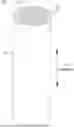

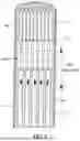
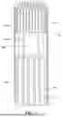

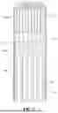
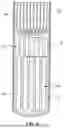
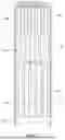


Sources:
- United States Patent and Trademark Office - verify current appl. status at the USPTO↗
Similar patent applications:
- » 20240341349
AEROSOL GENERATING ARTICLE, SYSTEM AND METHOD OF MANUFACTURING AEROSOL GENERATING ARTICLE - » 20230404134
AEROSOL-GENERATING ARTICLE SYSTEM WITH OLFACTORY MALODOR INHIBITION - » 20180310623
Aerosol generating article, aerosol-generating system and method for manufacturing an aerosol-generating article - » 20190208813
AEROSOL-GENERATING ARTICLE, AEROSOL-GENERATING SYSTEM AND METHOD FOR MANUFACTURING AN AEROSOL-GENERATING ARTICLE - » 20250160385
SYSTEM FOR MANUFACTURING AEROSOL GENERATING MEDIUM, METHOD OF MANUFACTURING AEROSOL GENERATING ARTICLE, AEROSOL GENERATING ARTICLE, AND AEROSOL GENERATING SYSTEM - » 20240188624
AEROSOL GENERATING ARTICLE INCLUDING LIQUID COMPOSITION AND AEROSOL GENERATING SYSTEM INCLUDING THE AEROSOL GENERATING ARTICLE - » 20200359678
Aerosol generating article and aerosol generating system - » 20210030062
Aerosol Generating Article, An Aerosol Generating System And A Method For Generating A Flavoured Aerosol - » 20210030068
Aerosol-generating system and aerosol-generating article for use in such a system - » 20180184713
Aerosol-generating system and aerosol-generating article for use in such a system
Recent applications in this class:
- » 20260130415 2026-05-14
Pleated Filter Material for Smoking Articles - » 20260130414 2026-05-14
DEVICE FOR FLUID FLOW MANAGEMENT AND FILTRATION - » 20260101923 2026-04-16
FILTER SECTION FOR FLAVOR INHALATION ARTICLE AND FLAVOR INHALATION ARTICLE - » 20250325021 2025-10-23
SMOKE FILTER FOR CIGARETTES AND OTHER SMOKING IMPLEMENTS - » 20250318574 2025-10-16
Cartridge Cigarette Filter - » 20250234919 2025-07-24
FILTER FOR SMOKING PRODUCTS AND METHOD FOR PRODUCING SUCH FILTERS - » 20250064107 2025-02-27
Smoking Filter - » 20250031751 2025-01-30
Cardboard Filter For Cigarettes, Cigarette And Manufacturing Method Thereof - » 20240397998 2024-12-05
SMOKING PRODUCT FILTER AND SMOKING PRODUCT COMPRISING SAME - » 20240358067 2024-10-31
METHOD AND APPARATUS FOR PRE-ROLL PAPERS OR WRAP WITH TIPS