FOLDING FRAME AND STORAGE CABINET
US20260150962A1
2026-06-04
19/085,987
2025-03-20
Smart Summary: A folding frame is designed with four fixed support rods arranged in a rectangle. These rods connect to a transverse folding rod and a vertical folding rod, allowing the frame to fold easily. A storage cabinet is built around this folding frame, featuring a drawer inside for storing items. Additionally, a cover plate can be placed on top of the frame and can be removed when needed. This design makes it convenient to store and access items while saving space. 🚀 TL;DR
Abstract:
The invention discloses a folding frame, including a fixed support rod, a transverse folding rod and a vertical folding rod; the number of the fixed support rods is four, the four fixed support rods are parallel to each other and are distributed in a rectangular shape, two ends of the two fixed support rods in the same transverse plane are both connected to a transverse folding rod, and two ends of the two fixed support rods in the same vertical plane are both connected to a vertical folding rod. The invention also discloses a storage cabinet, including a folding frame, a drawer and a cover plate; the drawer is disposed inside the folding frame for providing a storage space; the cover plate is removably mounted on top of the folding frame.
Applicant:
Interested in similar patents?
Get notified when new applications in this technology area are published.
Classification:
A47B43/00 » CPC main
Cabinets; Racks; Shelf units; Similar furniture; Similar features of built-in cupboards
A47B43/00 » CPC main
Cabinets, racks or shelf units, characterised by features enabling folding of the cabinet or the like
A47B87/0207 » CPC further
Sectional furniture, i.e. combinations of complete furniture units, e.g. assemblies of furniture units of the same kind such as linkable cabinets, tables, racks or shelf units stackable ; stackable and linkable Stackable racks, trays or shelf units
A47B87/02 IPC
Sectional furniture, i.e. combinations of complete furniture units, e.g. assemblies of furniture units of the same kind such as linkable cabinets, tables, racks or shelf units stackable ; stackable and linkable
Description
TECHNICAL FIELD
The invention relates to the field of storage cabinet, and more particularly, to a folding frame and a storage cabinet.
BACKGROUND ART
The storage cabinet is a furniture or a storage device for storing and arranging various articles. From the functional point of view, it is mainly to provide an independent area with a certain spatial division, place scattered articles centrally, and make the home, office or other space more clean and orderly. For example, in a home environment, different types of articles, such as clothing, toys, documents, tableware, etc. can be stored separately by a storage cabinet, avoiding random stacking of the articles and causing space clutter. In view of structural features, the storage cabinet typically has one or more enclosed or semi-enclosed spaces. These spaces can be drawer-type, like a file storage cabinet under a desk, and the drawer can be pulled out and pushed in smoothly, so as to facilitate the storage and access of small articles such as stationery and paper; it may also be a cabinet door type, such as a wardrobe, which exhibits a structure such as a hanging rod and a partition inside when the cabinet door is opened, and is used for hanging clothes or stacking beddings.
Currently, there are many types of storage cabinets on the market, but most of them have the following defects:
-
- (1) most of the existing storage cabinets on the market need to be mounted with accessories such as screws and bolts and corresponding tools; the assembly time is long, and the product cannot be assembled if the accessories are missing or the consumer is not familiar with the mounting skills;
- (2) most of the existing storage cabinets in the market have more packaging pad lining materials, large overall package size, heavy weight, high packaging and transportation costs;
- (3) most of the existing storage cabinets in the market cannot guarantee the better stability of the frame structure while meeting the folding storage, which makes the user experience poor.
Accordingly, the present invention provides a folding frame and a storage cabinet to solve the above-mentioned problems.
SUMMARY OF THE INVENTION
It is an object of the invention to provide a folding frame and a storage cabinet which ensure the stability of the storage cabinet while reducing the packaging and transportation costs of the storage cabinet and improving the use experience of a user.
In order to solve the above technical problem, the invention provides a folding frame comprising a fixed support rod, a transverse folding rod and a vertical folding rod;
-
- the number of the fixed support rods is four, the four fixed support rods are parallel to each other and are distributed in a rectangular shape, two ends of the two fixed support rods in the same transverse plane are both connected to a transverse folding rod, and two ends of the two fixed support rods in the same vertical plane are both connected to a vertical folding rod;
- when the vertical folding rod and the transverse folding rod are all in a fully unfolded state, the fixed support rod, the transverse folding rod and the vertical folding rod are combined to form a hexahedral frame structure, wherein the main body portions of the vertical folding rod and the transverse folding rod are respectively stabilized using a first fastener and a second fastener, and the ends of the transverse folding rod and the vertical folding rod are respectively stabilized using a third fastener and a fourth fastener between the fixed support rod;
- when the vertical folding rod and the transverse folding rod are fully folded, the four fixed support rods are close together to form an elongated cuboid structure, and the vertical folding rod and the transverse folding rod are fully folded and received inside the fixed support rods.
Further, the main body portion of the vertical folding rod comprises two hinged straight rods, and the first fastener comprises an elongated engagement post;
-
- the engagement post is mounted at the end of one straight rod of the vertical folding rod, and the inside of the other straight rod of the vertical folding rod has a fixing groove;
- when the vertical folding rod is fully unfolded, the engagement post is embedded and clamped in the fixing groove.
Further, the main body portion of the transverse folding rod comprises two hinged straight rods, and the second fastener comprises an elastic block;
-
- the end face of the elastic block has a first circular bump;
- the end faces of the two straight rods of the transverse folding rod close to the connecting ends of each other are both provided with the elastic block and a first groove matching the first circular bump;
- when the transverse folding rod is fully unfolded, the first circular bump is submerged in the first groove.
Further, the third fastener comprises a second circular bump;
-
- the second circular bump is provided on the fixed support rod;
- an end side wall of the transverse folding rod has a second groove matching the second circular bump;
- when the transverse folding rod is fully unfolded, the second circular bump is submerged in the second groove.
Further, the fourth fastener comprises a third circular bump;
-
- the third circular bump is provided on the fixed support rod;
- an end side wall of the vertical folding rod has a third groove matching the third circular bump;
- when the vertical folding rod is fully unfolded, the third circular bump is submerged in the third groove.
Further, the end of the transverse folding rod has an arc-shaped abutment and the end of the vertical folding rod has an accommodating groove;
-
- when the transverse folding rod and the vertical folding rod are fully unfolded, the arc-shaped abutment is located in the accommodating groove and abuts against an inner side wall of the accommodating groove.
Further, the side walls at both ends of the fixed support rod are provided with first connecting through holes for mounting rivet members.
Further, both sides of the end face of the fixed support rod are provided with second connecting through holes for mounting rivet members.
Further, the end faces of the upper two of the fixed support rods have positioning concave grooves and the end faces of the lower two of the fixed support rods have positioning convex strips matching the positioning concave grooves.
The invention also provides a storage cabinet comprising a folding frame, a drawer and a cover plate as described above;
-
- the drawer is disposed inside the folding frame for providing a storage space;
- the end face of the cover plate has a plurality of rivet members, and the rivet members on the cover plate cooperate with the second connecting through holes on the top of the folding frame that the cover plate can be detachably mounted on the top of the folding frame.
Compared to the prior art, the invention has at least the following advantageous effects:
-
- (1) the folding frame provided by the invention achieves the folding function of the folding frame by the arrangement of four fixed support rods, four vertical folding rods and four transverse folding rods, wherein after the folding, the vertical folding rods and the transverse folding rods are completely received inside the fixed support rods to form an elongated cuboid structure with the four fixed support rods as the main body profile, so as to ensure a better occupied volume of the folding frame after the folding, thereby reducing the packaging cost and the transportation cost of the product;
- (2) the folding frame provided in the invention is a regular hexahedral frame structure after unfolding, and the first fastener, the second fastener and the third fastener stabilize the folding activity point of the folding frame in an all-directional manner, ensuring the excellent stability of the regular hexahedral frame structure formed after the folding frame is unfolded;
- (3) in the storage cabinet provided in the invention, a user only needs to pull a fixed support rod of a folding frame to make the folding frame form a hexahedral frame structure when assembling, then a drawer is inserted into the hexahedral frame structure formed by the folding frame, and a cover plate is buckled on the top of the hexahedral frame structure formed by the folding frame, which is simple in operation and does not need to use a tool and a complicated connecting piece, thus reducing the difficulty in assembling a product, thereby effectively improving the user experience;
- (4) the storage cabinet provided in the invention has good stability after the single body is assembled, and a user can perform stable and free combination of a plurality of storage cabinets so as to satisfy personalized customization requirements of the user for a storage space, thereby further improving the user experience;
- (5) the invention provides a storage cabinet, wherein a drawer and a cover plate thereof are of a separable design with a folding frame, and at the same time, the folding frame can be folded into an elongated cuboid structure with four fixed support rods as a main profile, so as to reduce the packaging cost and transportation cost of a product, and at the same time facilitate the user to carry and transfer the storage cabinet.
BRIEF DESCRIPTION OF THE DRAWINGS
FIG. 1 is a schematic view showing the overall structure of a folding frame of the invention completely unfolded;
FIG. 2 is a schematic view showing the overall structure of the folding frame of the invention completely folded;
FIG. 3 is an enlarged view showing the structure at C in FIG. 1 of the invention;
FIG. 4 is an enlarged view showing the structure at A in FIG. 1 of the invention;
FIG. 5 is a schematic view showing the distribution of a first groove on a transverse folding rod in the folding frame of the invention;
FIG. 6 is a schematic view showing the distribution of a first circular bump and a second groove on the transverse folding rod in the folding frame of the invention;
FIG. 7 is a schematic view showing the distribution of a second circular bump and a third circular bump on a fixed support rod in the folding frame of the invention;
FIG. 8 is a schematic view showing the distribution of a third groove in a vertical folding rod in the folding frame of the invention;
FIG. 9 is an enlarged view showing the structure at B in FIG. 1 of the invention;
FIG. 10 is a schematic view showing the structure of a rivet member for connecting a plurality of folding frames of the invention;
FIG. 11 is a schematic view showing a horizontal arrangement connections between the plurality of folding frames of the invention;
FIG. 12 is a schematic view showing a vertically stacked connection between the plurality of folding frames of the invention;
FIG. 13 is a schematic view showing an overall structure of a storage cabinet of the invention;
FIG. 14 is a schematic view showing a state of the folding frame of the invention when the vertical folding rod is half-folded;
FIG. 15 is a schematic view showing a state of the folding frame of the invention when the vertical folding rods is fully unfolded;
FIG. 16 is a schematic view showing a state of the folding frame of the invention when the transverse folding rod is half-folded;
FIG. 17 is a schematic view showing a plurality of storage cabinets of the invention in a vertically stacked arrangement;
FIG. 18 is a schematic view showing a plurality of storage cabinets of the invention in a horizontal arrangement;
FIG. 19 is a schematic view showing a combination of vertically stacked and horizontal arrangement between a plurality of storage cabinets of the invention;
FIG. 20 is a schematic view showing a structure of a cover plate in a storage cabinet of the invention;
FIG. 21 is a schematic view showing the position of the first circular bump when the transverse folding rod of the folding frame of the invention is completely unfolded;
FIG. 22 is a schematic view showing the position of the positioning protrusion strip in the folding frame of the invention.
DETAILED DESCRIPTION OF THE INVENTION
A folding frame and a containing box of the invention will now be described in more detail with reference to the schematic drawings showing preferred embodiments of the invention, it being understood that one skilled in the art can modify the invention described herein while still achieving the advantageous effects of the invention. Accordingly, the following description should be construed as broadly as known to those skilled in the art, and not as a limitation on the invention.
The invention is described in more detail in the following paragraphs by way of example with reference to the accompanying drawings. Advantages and features of the invention will become apparent from the following description. It is to be noted that the drawings are in a very simplified form and are not to precise scale, which is provided for the purpose of facilitating and clearly illustrating embodiments of the present invention.
Embodiment 1
-
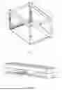
- As shown in FIGS. 1 and 2, the embodiment proposes a folding frame, comprising a fixed support rod 1, a transverse folding rod 2 and a vertical folding rod 3;
- wherein the number of the fixed support rods 1 is four, the four fixed support rods 1 are parallel to each other and are distributed in a rectangular shape, two ends of two fixed support rods 1 in the same transverse plane are both connected to a transverse folding rod 2, and two ends of two fixed support rods 1 in the same vertical plane are both connected to a vertical folding rod 3.
When the vertical folding rod 3 and the transverse folding rod 2 are in a fully unfolded state, the fixed support rod 1, the transverse folding rod 2 and the vertical folding rod 3 are combined to form a hexahedral frame structure, as shown in FIG. 1.
When the vertical folding rod 3 and the transverse folding rod 2 are both fully folded, the four fixed support rods 1 are close together to form an elongated cuboid structure, and the vertical folding rod 3 and the transverse folding rod 2 are fully folded and received inside the fixed support rods 1, as shown in FIG. 2.
In the above-mentioned embodiment, when the folding frame is in a fully unfolded state, the folding frame is a hexahedral frame structure, which can be used as a main framework of a storage cabinet, and when the folding frame is in a fully folded state, the folding frame is an elongated cuboid structure, so as to ensure a better occupied volume of the folding frame after folding, thereby reducing the packaging cost and transportation cost of a product.
In the above-mentioned embodiment, the vertical folding rod 3 has its main body portion secured by a first fastener, the transverse folding rod 2 has its main body portion secured by a second fastener, and the ends of the transverse folding rod 2 and the vertical folding rod 3 are respectively stabilized using a third fastener and a fourth fastener between the fixed support rod 1.
The first fastener, the second fastener and the third fastener stabilize the folding movable point of the folding frame in an all-directional manner, so as to ensure the excellent stability of the regular hexahedral frame structure formed after the folding frame is unfolded, thereby ensuring the stability of the storage cabinet using the folding frame as the main framework.
In the above-mentioned implementation process, specifically, with reference to FIG. 3, the main body portion of the vertical folding rod 3 comprises two hinged straight rods, and the first fastener comprises an engagement post 31 in the form of an elongated shape;
-
- the engagement post 31 is mounted at the end of one straight rod of the vertical folding rod 3, and the inside of the other straight rod of the vertical folding rod 3 has a fixing groove 32;
- when the vertical folding rod is fully unfolded, the engagement posts 31 are embeded and clamped in the fixing grooves 32, thereby achieving effective stabilization of the main body portion of the vertical folding rod 3 after it is unfolded.
With reference to FIGS. 4-6, the main body portion of the transverse folding rod 2 comprises two hinged straight rods, and the second fastener comprises an elastic block 21;
-
- the end face of the elastic block 21 has a first circular bump 22;
- the end faces of the two straight rods of the transverse folding rod 2 close to the connecting ends of each other are both provided with the elastic block 21 and a first groove 23 matching the first circular bump 22;
With reference to FIG. 21, when the transverse folding rod 2 is fully unfolded, the first circular bump 22 is submerged in the first groove 23, achieving effective stabilization of the main body portion of the transverse folding rod 2 after unfolding.
With reference to FIG. 7, the third fastener comprises a second circular bump 11;
-
- the second circular bump 11 is provided on the fixed support rod 1;
- the transverse folding rod 2 has a second groove 25 matching the second circular bump 11;
- when the transverse folding rod 2 is fully unfolded, the second circular bumps 11 are submerged in the second grooves 25, achieving an effective stabilization of the ends of the transverse folding rod 2 when it is fully unfolded.
In another embodiment of the invention, the third fastener can adopt a structural form different from the second circular bump 11 and the second groove 25. For example, the third fastener can adopt a snap structure, a magnetic attraction structure, or other connection mechanisms capable of realizing the unfolding locking function of the transverse folding rod 2, and can even completely omit the second circular bump 11 and the second groove 25.
With reference to FIG. 8, the fourth fastener comprises a third circular bump 14;
-
- the third circular bump 14 is provided on the fixed support rod 1;
- an end side wall of the vertical folding rod 3 has a third groove 34 matching the third circular bump 14;
- when the vertical folding rod 3 is fully unfolded, the third circular bump 14 is submerged in the third groove 34, achieving effective stabilization of the end of the vertical folding rod 3 when it is fully unfolded.
Similarly, in yet another embodiment of the invention, the fourth fastener can also adopt a structural form different from the third circular bump 14 and the third groove 34, or completely omit the third circular bump 14 and the third groove 34. In this case, the unfolding locking function of the vertical folding rod 3 can be realized through other mechanisms, or rely on the support of the overall structure to maintain the unfolded state.
Further, with reference to FIG. 9, an end of the transverse folding rod 2 has an arc-shaped abutment 24, and an end of the vertical folding rod 3 has a accommodating groove 33. When both the transverse folding rod 2 and the vertical folding rod 3 are fully unfolded, the arc-shaped abutment 24 is located in the accommodating groove 33 and abuts against an inner side wall of the accommodating groove 33, so that the end of the vertical folding rod 3 is clamped between the side edge of the fixed support rod 1 and the transverse folding rod 2, and further stabilization of the end of the vertical folding rod 3 when it is fully unfolded is achieved.
In a specific embodiment, the side walls of both ends of the fixed support rod 1 are provided with a first connecting through hole 12 for mounting a rivet member.
By the arrangement of the first connecting through holes 12, a stable connection between a plurality of folding frames placed horizontally can be achieved.
Specifically, the connection between the plurality of horizontally disposed folding frames employs a rivet a as shown in FIG. 10, which has a plug b1 and a plug b2 at both ends thereof, respectively. As shown in FIG. 11, the two folding frames are horizontally placed, and the plug b1 is inserted into the first connecting through hole 12 of one folding frame, and the plug b2 is inserted into the first connecting through hole 12 at the corresponding position of the other folding frame, so that the two folding frames are stably connected in the horizontal direction.
At the same time, both sides of the end face of the fixed support rod 1 are provided with a second connecting through hole 13 for mounting a rivet member.
By the arrangement of the second connecting through holes 13, a stable connection between a plurality of vertically stacked folding frames can be achieved.
Specifically, the connection between the plurality of vertically stacked folding frames may also employ the rivet a as described above. As shown in FIG. 12, two folding frames are vertically stacked, and the plug b1 is inserted into the second connecting through hole 13 of one folding frame, and the plug b2 is inserted into the second connecting through hole 13 at the corresponding position of the other folding frame, so as to achieve a stable connection of the two folding frames in the vertical direction.
It should be noted that the rivet a disclosed above is merely a plastic rivet in the prior art, and other structural types of plastic rivets, such as a plastic rivet having two umbrella-shaped plugs, a plastic rivet having two tree-shaped protruding plugs, etc. can be used when connecting two folding frames, which are not described in more detail herein.
Further, With reference to FIG. 22, end faces of two of the stay rods 1 located above in the folding frame have a positioning concave groove 16, and end faces of the lower two of the fixed support rods 1 have a positioning convex strip 15 matching the positioning concave groove 16.
When the plurality of folding frames are engaged in the vertical direction, the positioning convex strip 15 in the upper folding frame is clamped in the positioning concave groove 16 in the lower folding frame, further improving the stability of the engagement of the plurality of folding frames in the vertical direction.
In the above-mentioned specific embodiment, stable and free combination can be achieved between the plurality of folding frames as the main body exoskeleton of the combined storage cabinet, ensuring the stability of the combined storage cabinet. With regard to the free combination of multiple folding frames, a user can choose to purchase multiple folding frames and matching rivets to perform the combination on his own, and the assembly is simple. It is also possible for the user to request that the products be packaged and delivered by the manufacturer, which can also effectively enhance the user's experience.
Embodiment 2
With reference to FIG. 13, the embodiment provides a storage cabinet using a folding frame as provided in embodiment 1 as a main framework, and specifically further comprises a drawer 4 and a cover plate 5;
-
- the drawer 4 is disposed inside the folding frame for providing a storage space;
- the cover plate 5 is detachably mounted on top of the folding frame.
In the above-mentioned embodiment, the storage cabinet uses a folding frame as set forth in embodiment 1 as a main body skeleton, and the drawer 4 and the cover plate 5 thereof are of a separable design with the folding frame, and at the same time, the folding frame can be folded into an elongated cuboid structure with four fixed support rods 1 as the main profile, thereby reducing the packaging cost and transportation cost of the product.
At the same time, a user merely needs to pull the fixed support rod 1 of the folding frame to make the folding frame form a hexahedral frame structure when assembling, then the drawer 4 is inserted into the hexahedral frame structure formed by the folding frame, and a cover plate 5 is buckled on the top of the hexahedral frame structure formed by the folding frame, which is simple in operation and does not need to use a tool and a complicated connecting piece, thus reducing the difficulty in assembling the product and improving the user experience.
Specifically, with reference to FIGS. 14 to 16, when unfolding a folding frame in a folded state, firstly, applying a tensile force F1 in a vertical direction to a fixed support rod 1 of the folding frame so as to gradually unfold a vertical folding rod 3 of the folding frame, and after the vertical folding rod 3 of the folding frame is completely unfolded, then applying a tensile force F2 in a horizontal direction to the fixed support rod 1 of the folding frame so as to gradually unfold a transverse folding rod 2 of the folding frame, the operation is simple.
In order to facilitate the user's understanding of how to unfold the folding frame, an indication arrow (not shown in the Figure) is optionally provided on the fixed support rod 1 to indicate the direction of the force applied, and a serial number is marked.
When the user needs to fold the unfolded folding frame, it is merely necessary to take the drawer 4 out of the folding frame, remove the cover plate 5, and then fold the folding frame, and the folding operation of the folding frame can be inferred from the unfolding operation, which will not be described in more detail herein. By folding the folding frame, it is convenient for the user to carry and transfer the storage cabinet.
Further, the folding frame stabilizes the folding movable point position of the folding frame in an all-directional manner via the first fastener, the second fastener and the third fastener, so as to ensure the excellent stability of the regular hexahedral frame structure formed after the folding frame is unfolded; the storage cabinet uses the folding frame as the main body skeleton, so that the storage cabinet has a good stability after a single body is assembled; at the same time, stable horizontal connection and vertical stacking connection can be performed between the folding frames, which enables a user to perform stable and free combination of multiple storage cabinets, and customize a desired combined storage cabinet, so as to satisfy the personalized customization requirement of the storage space thereof. The user experience is further enhanced.
Specifically, in order to explain how to customize a desired combined storage cabinet, a combination of three storage cabinets is described here.
As shown in FIG. 17, the combined storage cabinet comprises three storage cabinets, wherein the three storage cabinets are vertically stacked, folding frames of two adjacent storage cabinets are connected via rivets a, three folding frames all have drawers 4, and a cover plate 5 is mounted on the topmost folding frame.
As shown in FIG. 18, the combined storage cabinet comprises three storage cabinets, wherein the three storage cabinets are horizontally arranged, folding frames of two adjacent storage cabinets are connected via rivets a, a drawer 4 is provided in all the three folding frames, and a cover plate 5 is mounted on the top of all the three folding frames.
The modular storage cabinets also be placed and connected in a vertically stacked and horizontally arranged combination as shown in FIG. 19.
Of course, the personalization of the combined storage cabinet not only lies in the different arrangement and combination modes of the storage cabinet, but also lies in the selection of the drawer 4 and the cover plate 5, and a user can select different materials and different colours of the drawer 4 and the cover plate 5 to use in combination according to personal preferences.
In the above-mentioned embodiment, after the user places a plurality of storage cabinets, the rivet a may not be used for connection, so that it is more convenient to access and place the storage cabinets located at a high position, and a certain stability between vertically stacked storage cabinets can also be ensured due to the arrangement of the positioning concave groove 16 and the positioning convex strip 15 in the folding frame.
In a particular embodiment, with reference to FIG. 20, the end face of the cover plate 5 has a plurality of rivet members, the rivet members on the cover plate 5 cooperating with the second connecting through holes 13 at the top of the folding frame.
Specifically, the rivet member on the cover plate 5 uses a rivet c as shown in FIG. 20, wherein one end of the rivet c has a plug d, and the other end of the rivet c is fixed on the cover plate 5; the stable mounting of the cover plate 5 and the folding frame is achieved by inserting the plug d into the second connecting through hole 13 at the top of the folding frame; and when it is necessary to disassemble the cover plate 5, the cover plate 5 can be pulled with a force, and the operation is simple.
In another embodiment of the invention, the connection between the cover plate 5 and the folding frame can adopt a structural form different from the rivet c and plug d shown in FIG. 20. For example, the cover plate 5 can be connected to the top of the folding frame through bolt connection, snap connection, magnetic attraction connection, or other detachable connection methods. The rivet c and plug d can even be completely omitted, and methods such as direct attachment can be used to install the cover plate 5 on the folding frame. An appropriate connection strength and disassembly difficulty can be selected according to actual usage requirements to meet the needs of different usage scenarios.
In an alternative embodiment, the storage cabinet further comprises a universal wheel (not shown in the Figure), which is mounted on the bottom of the folding frame and can be inserted into the second connecting through hole 13 of the bottom of the folding frame via the rivet c as described above, so that the mounting is convenient, and the flexibility of the storage cabinet is improved.
Further, the universal wheel has a foot brake to ensure good stability of the storage cabinet.
Of course, the second connecting through hole 13 at the bottom of the folding frame is not limited to the mounting of the universal wheel, and the mounting of the support leg may be selected to suspend the storage cabinet and improve the moisture-proof effect of the storage cabinet. The mounting mode of the support legs is the same as the mounting mode of the universal wheel, which will not be described in more detail herein.
In summary, the folding frame and the storage cabinet provided by the invention have the following advantages over the prior art:
-
- (1) the folding frame provided by the invention achieves the folding function of the folding frame by the arrangement of four fixed support rods, four vertical folding rods and four transverse folding rods, wherein after the folding, the vertical folding rods and the transverse folding rods are completely received inside the fixed support rods to form an elongated cuboid structure with the four fixed support rods as the main body profile, so as to ensure a better occupied volume of the folding frame after the folding, thereby reducing the packaging cost and the transportation cost of the product;
- (2) the folding frame provided in the invention is a regular hexahedral frame structure after unfolding, and the first fastener, the second fastener and the third fastener stabilize the folding activity point of the folding frame in an all-directional manner, ensuring the excellent stability of the regular hexahedral frame structure formed after the folding frame is unfolded;
- (3) in the storage cabinet provided in the invention, a user only needs to pull a fixed support rod of a folding frame to make the folding frame form a hexahedral frame structure when assembling, then a drawer is inserted into the hexahedral frame structure formed by the folding frame, and a cover plate is buckled on the top of the hexahedral frame structure formed by the folding frame, which is simple in operation and does not need to use a tool and a complicated connecting piece, thus reducing the difficulty in assembling a product, thereby effectively improving the user experience;
- (4) the storage cabinet provided in the invention has good stability after the single body is assembled, and a user can perform stable and free combination of a plurality of storage cabinets so as to satisfy personalized customization requirements of the user for a storage space, thereby further improving the user experience;
- (5) the invention provides a storage cabinet, wherein a drawer and a cover plate thereof are of a separable design with a folding frame, and at the same time, the folding frame can be folded into an elongated cuboid structure with four fixed support rods as a main profile, so as to reduce the packaging cost and transportation cost of a product, and at the same time facilitate the user to carry and transfer the storage cabinet.
It will be apparent to those skilled in the art that various modifications and variations can be made in the invention without departing from the spirit or scope of the inventions. Thus, if such modifications and variations of the invention fall within the scope of the claims of the invention and their equivalents, the invention is also intended to include such modifications and variations.
Claims
1. A folding frame, characterized by comprising a fixed support rod, a transverse folding rod and a vertical folding rod; wherein
the number of the fixed support rods is four, the four fixed support rods are parallel to each other and are distributed in a rectangular shape, two ends of the two fixed support rods in the same transverse plane are both connected to a transverse folding rod, and two ends of the two fixed support rods in the same vertical plane are both connected to a vertical folding rod;
when the vertical folding rod and the transverse folding rod are all in a fully unfolded state, the fixed support rod, the transverse folding rod and the vertical folding rod are combined to form a hexahedral frame structure, wherein the main body portions of the vertical folding rod and the transverse folding rod are respectively stabilized using a first fastener and a second fastener, and the ends of the transverse folding rod and the vertical folding rod are respectively stabilized using a third fastener and a fourth fastener between the fixed support rod;
when the vertical folding rod and the transverse folding rod are fully folded, the four fixed support rods are close together to form an elongated cuboid structure, and the vertical folding rod and the transverse folding rod are fully folded and received inside the fixed support rods.
2. The folding frame according to claim 1, characterized in that the main body portion of the vertical folding rod comprises two hinged straight rods and the first fastener comprises an elongated engagement post;
the engagement post is mounted at the end of one straight rod of the vertical folding rod, and the inside of the other straight rod of the vertical folding rod has a fixing groove;
when the vertical folding rod is fully unfolded, the engagement post is embedded and clamped in the fixing groove.
3. The folding frame according to claim 1, characterized in that the main body portion of the transverse folding rod comprises two hinged straight rods and the second fastener comprises an elastic block;
an end face of the elastic block has a first circular bump;
end faces of the two straight rods of the transverse folding rod close to the connecting ends of each other are both provided with the elastic block and a first groove matching the first circular bump;
when the transverse folding rod is fully unfolded, the first circular bump is submerged in the first groove.
4. The folding frame according to claim 1, characterized in that the third fastener comprises a second circular bump;
the second circular bump is provided on the fixed support rod;
an end side wall of the transverse folding rod has a second groove matching the second circular bump;
when the transverse folding rod is fully unfolded, the second circular bump is submerged in the second groove.
5. The folding frame according to claim 1, characterized in that the fourth fastener comprises a third circular bump;
the third circular bump is provided on the fixed support rod;
an end side wall of the vertical folding rod has a third groove matching the third circular bump;
when the vertical folding rod is fully unfolded, the third circular bump is submerged in the third groove.
6. The folding frame according to claim 1, characterized in that the end of the transverse folding rod has an arc-shaped abutment and the end of the vertical folding rod has an accommodating groove;
when the transverse folding rod and the vertical folding rod are fully unfolded, the arc-shaped abutment is located in the accommodating groove and abuts against an inner side wall of the accommodating groove.
7. The folding frame according to claim 1, characterized in that the side walls at both ends of the fixed support rod are provided with first connecting through holes for mounting rivet members.
8. The folding frame according to claim 1, characterized in that both sides of the end face of the fixed support rod are provided with second connecting through holes for mounting rivet members.
9. The folding frame according to claim 1, characterized in that the end faces of the upper two of the fixed support rods have positioning concave grooves and the end faces of the lower two of the fixed support rods have positioning convex strips matching the positioning concave grooves.
10. A storage cabinet, characterized by comprising the folding frame according to claim 1, a drawer and a cover plate; wherein
the drawer is disposed inside the folding frame for providing a storage space;
an end face of the cover plate has a plurality of rivet members, and the rivet members on the cover plate cooperate with the second connecting through holes on the top of the folding frame that the cover plate can be detachably mounted on the top of the folding frame.
Images & Drawings included:


Sources:
- United States Patent and Trademark Office - verify current appl. status at the USPTO↗
Recent applications in this class:
- » 20260096646 2026-04-09
Articulating Modular Storage System - » 20260060417 2026-03-05
Collapsible Furniture Cabinet - » 20260041233 2026-02-12
Foldable Storage Cabinet - » 20250375032 2025-12-11
FOLDING CONNECTING MEMBER, FOLDING SUPPORTING STRUCTURE, AND FOLDING CABINET - » 20250288095 2025-09-18
STORAGE CABINET - » 20250213033 2025-07-03
STORAGE SHELF FOR TOOL-FREE CABINET ASSEMBLY - » 20250185816 2025-06-12
Foldable Support Frame - » 20250176709 2025-06-05
FOLDABLE CARRYING EQUIPMENT - » 20250160512 2025-05-22
COLLAPSIBLE STORAGE CABINET - » 20250143455 2025-05-08
FOLDABLE CABINET